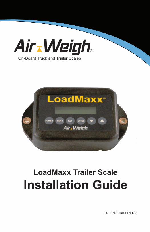
LoadMaxx Trailer Scale
Installation Guide
PN:901-0130-001 R2
On-Board Truck and Trailer Scales

2
Contents
LoadMaxx Overview........................................................................1 Table1:LoadMaxxTrailerSpecifications...........................................2
InstallationOverview.............................................................................3
Tools Required........................................................................4
Mounting the Scale..........................................................................5 MountingFlushtotheTrailer................................................................5
MountingWithaVanBracket...............................................................7
MountingWithaFrameRailBracket...................................................8
Installing Air Sensors......................................................................9Routing Cables...............................................................................11 RoutingtheSensorCableforaSingleSensor................................11
RoutingSensorCablesforTwoSensors..........................................13
RoutingSensorCablesforaFullTrailer............................................14
Connecting Power to the Scale....................................................15 ConnectingPowerwiththeABSConnector.....................................15
ConnectingPowertotheJunctionBox.............................................17
Installing an Alarm.........................................................................18Checking for Correct Installation................................................19 A/DReadingsandSignificance.........................................................19
Limited Warranty...........................................................................20Procedure For Warranty Claims..................................................21
1
Section 1LoadMaxx Overview
LoadMaxxTrailerisaweighingsystemforsemitrailersandfulltrailers.Thescaleworksusingsensorsthatmeasureairpressurechangesinthetrailer’ssuspension;itthenconvertsthosenumbersintoweight.TheweightisdisplayedontheLoadMaxxtrailerdisplay.LoadMaxxdisplaysweightperaxlegroup.Weightsareaccuratetowithin300pounds(140kilograms)andaredisplayedin20-poundor20-kilogramincrements.
IfyouareusingLoadMaxxTrailerinconjunctionwithaLoadMaxxTractorscale,thetrailerweightswillalsodisplayinthetruckcab.DataistransmittedthroughtheexistingJ560cable,soyouwillnotneedtoinstallaspecialtractor/trailerconnection.Youcanalsousetractorandtrailerscaleswithdrop-and-hooksetups.
ThisinstallationguideprovidesinstallationinformationforthreeLoadMaxxtrailerscalemodelnumberslistedasfollows.Ifyouareusingalesscosuchasthepayloadtrailerscale,shouldcontactSupportforfurtherinformation.
5802-Semitrailerwithasingleheightcontrolvalve
5804-Semitrailerwithdualheightcontrolvalves
5882-Fulltrailerwithtwoaxlegroups
Note: After installing your trailer scale, you must calibrate the scale before it will display accurate weights. Please see the LoadMaxx Trailer User Guide and our informational calibration videos, both available on our website, for more information.
LoadMaxx Overview

2
LoadMaxx Overview
Table 1: LoadMaxx Trailer SpecificationsAttribute LoadMaxx Specification
Width 6.4inches(162.56mm)Height 3.9inches(99.06mm)Depth 1.9inches(48.26mm)
1.5inches(38.1mm)notincludingDeuschconnector(forflushmountedapplications
Weight .85pounds(.386kg)Temperaturerange -40° to 185° F (-40° to 85° C)Inpultvoltagerange 9.5to32VDCAlarmcircuitcurrentlimit 1.0ampsEnvironmentalspecs Weatherized(immersionto
IP67)formountinginexteriorlocations

3
Installation Overview
TherearethreecomponentsoftheLoadMaxxscalethatyouwillinstall:
• Scaleandmountingbracket(unlessflushmounted)
• Airsensor(s)
• Sensorandpowercables
SeeFig.1foranillustrationoftheinstallationoverview.
ForafulllistofpartsinyourLoadMaxxscalekit,seethePartsListincludedinyourkit.
Installation Overview | Tools Required
Fig. 1 Installation Overview
4
Tools RequiredYouwillneedthefollowingtoolstoinstallthescaleandsensor.
• Standardwrenchsetoradjustablewrench
• Drillwith1/4-inchdrillbit
• Holesawfor15/8-inchdrillbit(neededonlywhenscaleisflushmounted)
• Flushwirecutter
• Teflonpipethreadtape
Installation Overview | Tools Required Mounting the Scale | Mounting Flush to Trailer
5
Section 2Mounting the Scale
Therearethreewaysyoucanmountthetrailerscale:flushmountedtothetrailerframeitself,usingavanbracket,andusingaframerailbracket.Theyareeachdescribedbelow.Choosethemountingmethodthatwillworkthebestwithyourtrailerconfiguration.Mountthetrailerscaleinapositionthatiseasytoviewwhileyouareloadingyourtrailer,andprotectedfromdirecttiresprayandroaddebris.Inregionswheresevereweatherisaconsideration,contactAir-Weighformoreinformationonprotectiveenclosures.
Note: Do not place strain the interface cable leading from the scale connector. A sharp bend in the cable could cause the environmental seal to fail.
Mounting Flush to the TrailerAflushmountedscaleismounteddirectlytothesideofthetrailer(Fig.2).
1. Determinethebestlocationtomountthescale.Thisshouldbeaflatareaofthetrailer,thinenoughtomakedrillingpossibleandaccessiblefrombothfrontandback.Makesurethebacksideofthelocationisfreeofobstaclesanddebristhatwouldinterferewiththeinstallation.
2. Cleanthemountingsurfaceusingisopropylalcoholswabs,providedwithyourhardwarekit.
3. Measuretotheexactcenterbetweenthemountingholes.Thisiswherecableconnectionswillemergefromthescale.Usingtheholesaw,drilla15/8-inchholethroughthetrailersurface.
Mounting the Scale | Mounting Flush to Trailer

6
4. Holdthescaleinthelocationyouwillmountit.Markthetrailersurfacethatisvisiblethroughtheholesoneithersideoftheplasticcasingusingapermanentmarker.
5. Usingthemarkedareasasaguide,drilltwo1/4-inchholesintothesurfaceofthetrailer.
6. Feedtheinterfacecablethroughthelargerholeyoudrilledinthetrailer.Plugitintothebackofthescale.
7. Placethescaleoverthespaceyouhavepreparedonthetrailer,makingsurethetwoholeslineupwiththeholesoneithersideofthescalecasing.Usetheprovidedbolts,nutsandwasherstosecurethescaletothesideofthetrailer(Fig.2).
Mounting the Scale | Mounting Flush to Trailer
Fig. 2 Mounting Flush to the Trailer
Mounting the Scale | Mounting with Van Bracket

7
Mounting the Scale | Mounting with Van Bracket
Mounting With a Van BracketAvanbracket(Fig.3)isusedprimarilytomounttheLoadMaxxtrailerscaletovanorrefrigeratedtrailers.However,youcanusethisbracketforanysurface-mountedinstallation
1. Determinethebestlocationtomountthescale.Thebracketscrewsshouldbemountedonaledge,andthescaleitselfshouldhangofftheledgewithnoobstaclesblockingit.
2. Holdthebracketinthelocationyouwillmountit.Markthetrailersurfacethatisvisiblethroughtheholesinthetopofthebracketusingapermanentmarker.
3. Usingthemarkedareasasaguide,drillthree1/4-inchholesintothesurfaceofthetrailer.
4. Feedtheinterfacecablethroughtheholeinthebackofthebracketandplugitintothebackofthescale.
5. Securethescaletothebracket.Insertoneboltthrougheachoftheholesinthetrailercasing.Secureinbackusingthesuppliednut.
6. Securethebrackettothetrailersurface.Insertaboltthrougheachoftheholesinthebracketandthroughtheholesyoudrilledinthetrailersurface.Secureinbackusinganut.
Fig. 3 Mounting with a Van Bracket
8
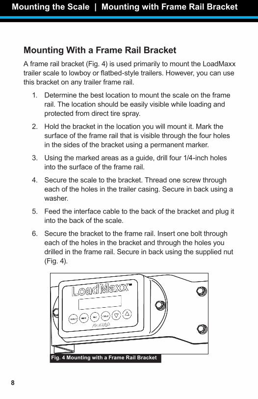
Mounting With a Frame Rail Bracket Aframerailbracket(Fig.4)isusedprimarilytomounttheLoadMaxxtrailerscaletolowboyorflatbed-styletrailers.However,youcanusethisbracketonanytrailerframerail.
1. Determinethebestlocationtomountthescaleontheframerail.Thelocationshouldbeeasilyvisiblewhileloadingandprotectedfromdirecttirespray.
2. Holdthebracketinthelocationyouwillmountit.Markthesurfaceoftheframerailthatisvisiblethroughthefourholesinthesidesofthebracketusingapermanentmarker.
3. Usingthemarkedareasasaguide,drillfour1/4-inchholesintothesurfaceoftheframerail.
4. Securethescaletothebracket.Threadonescrewthrougheachoftheholesinthetrailercasing.Secureinbackusingawasher.
5. Feedtheinterfacecabletothebackofthebracketandplugitintothebackofthescale.
6. Securethebrackettotheframerail.Insertoneboltthrougheachoftheholesinthebracketandthroughtheholesyoudrilledintheframerail.Secureinbackusingthesuppliednut(Fig.4).
Mounting the Scale | Mounting with Frame Rail Bracket
Fig. 4 Mounting with a Frame Rail Bracket
Installing Air Sensors
9
Section 3Installing Air Sensors
Note: Avoid dropping sensors. Dropping can cause the sensors to fail immediately or shorten their lifespan.
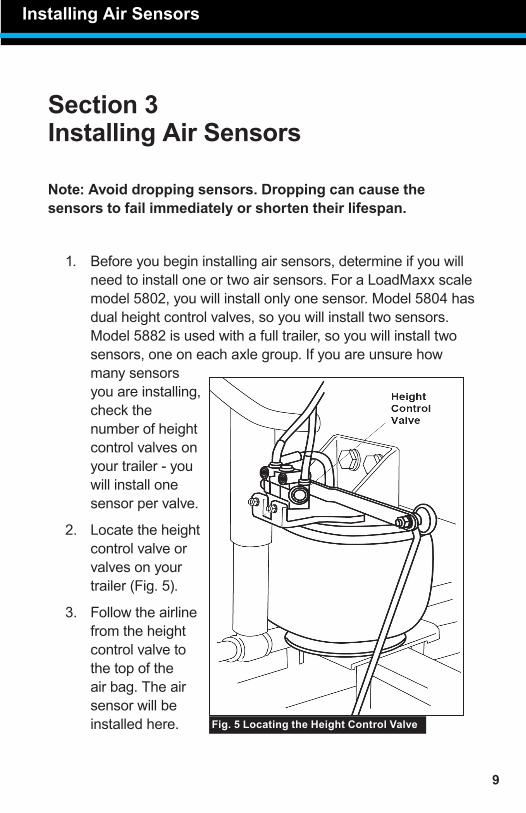
1. Beforeyoubegininstallingairsensors,determineifyouwillneedtoinstalloneortwoairsensors.ForaLoadMaxxscalemodel5802,youwillinstallonlyonesensor.Model5804hasdualheightcontrolvalves,soyouwillinstalltwosensors.Model5882isusedwithafulltrailer,soyouwillinstalltwosensors,oneoneachaxlegroup.Ifyouareunsurehowmanysensorsyouareinstalling,checkthenumberofheightcontrolvalvesonyourtrailer-youwillinstallonesensorpervalve.
2. Locatetheheightcontrolvalveorvalvesonyourtrailer(Fig.5).
3. Followtheairlinefromtheheightcontrolvalvetothetopoftheairbag.Theairsensorwillbeinstalledhere.
Installing Air Sensors
Fig. 5 Locating the Height Control Valve

10
4. Detachtheairlineconnectionfromthetopoftheairbag.
5. InsertthebrassTfittingprovidedinyourtrailerkitintothetopoftheairbag.Tightenassecurelyaspossible.
6. InserttheairlineintothetopoftheTfitting.
7. ConnecttheairlinefittingtothesideofthebrassTfitting.Tightenassecurelyaspossible.
8. Inserttheairsensorintotheairlinefitting.Pushuntilthesensorsitssecurely.Pulllightlyonthesensortotestforafirmconnection.SeeFig.6foradiagramoftheTfittingandsensorsetup.
Installing Air Sensors
Fig. 6 Fitting and Air Sensor Setup
Routing Cables | Routing Sensor Cable for Single Sensor
11
Section 4Routing Cables
DependingonwhetheryouareinstallingLoadMaxxonatrailerwithasingleheightcontrolvalve,adualheightcontrolvalve,oronafulltrailer,theprocessofroutingsensorcableswilldifferslightly.Followtheinstructionsintheapplicablesection.
Note: If your trailer has a sliding suspension, route all cables with the existing wiring harness. Improper routing could damage cables when the slider is moved.
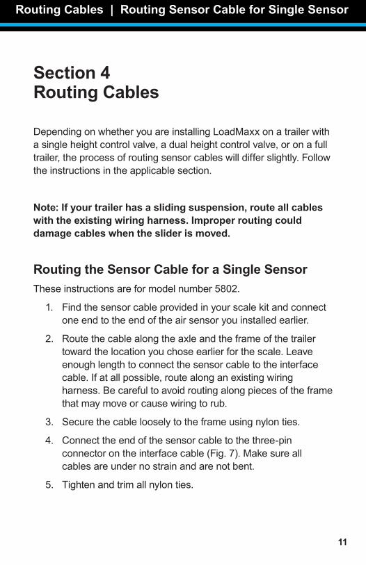
Routing the Sensor Cable for a Single SensorTheseinstructionsareformodelnumber5802.
1. Findthesensorcableprovidedinyourscalekitandconnectoneendtotheendoftheairsensoryouinstalledearlier.
2. Routethecablealongtheaxleandtheframeofthetrailertowardthelocationyouchoseearlierforthescale.Leaveenoughlengthtoconnectthesensorcabletotheinterfacecable.Ifatallpossible,routealonganexistingwiringharness.Becarefultoavoidroutingalongpiecesoftheframethatmaymoveorcausewiringtorub.
3. Securethecablelooselytotheframeusingnylonties.
4. Connecttheendofthesensorcabletothethree-pinconnectorontheinterfacecable(Fig.7).Makesureallcablesareundernostrainandarenotbent.
5. Tightenandtrimallnylonties.
Routing Cables | Routing Sensor Cable for Single Sensor
12
Routing Cables | Routing Sensor Cable for Single Sensor
Fig. 7 interface Cable for Single Sensor
Routing Cables | Routing Sensor Cables for Two Sensors
13
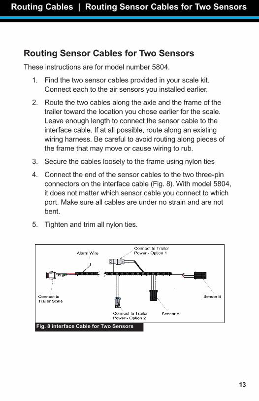
Routing Sensor Cables for Two SensorsTheseinstructionsareformodelnumber5804.
1. Findthetwosensorcablesprovidedinyourscalekit.Connecteachtotheairsensorsyouinstalledearlier.
2. Routethetwocablesalongtheaxleandtheframeofthetrailertowardthelocationyouchoseearlierforthescale.Leaveenoughlengthtoconnectthesensorcabletotheinterfacecable.Ifatallpossible,routealonganexistingwiringharness.Becarefultoavoidroutingalongpiecesoftheframethatmaymoveorcausewiringtorub.
3. Securethecableslooselytotheframeusingnylonties
4. Connecttheendofthesensorcablestothetwothree-pinconnectorsontheinterfacecable(Fig.8).Withmodel5804,itdoesnotmatterwhichsensorcableyouconnecttowhichport.Makesureallcablesareundernostrainandarenotbent.
5. Tightenandtrimallnylonties.
Routing Cables | Routing Sensor Cables for Two Sensors
Fig. 8 interface Cable for Two Sensors

14
Routing Sensor Cables for a Full TrailerTheseinstructionsareformodelnumber5882.
1. Findthetwosensorcablesprovidedinyourscalekit.Connectsensorcabletoeachtotheairsensorsyouinstalledearlier.
2. Routethetwocablesalongtheaxleandtheframeofthetrailertowardthelocationyouchoseearlierforthescale.Leaveenoughlengthtoconnectthesensorcabletotheinterfacecable.Ifatallpossible,routealonganexistingwiringharness.Becarefultoavoidroutingalongpiecesoftheframethatmaymoveorcausewiringtorub.
3. Securethecableslooselytotheframeusingnylonties.
4. Connecttheendofthesensorcablestothetwothree-pinconnectorsontheinterfacecable.ConnectthesensorcableforthefrontaxlegrouptoSensorA,andthesensorcablefortherearaxlegrouptoSensorB.
5. Tightenandtrimallnylonties.
Routing Cables | Routing Sensor Cables for Full Trailer Connecting Power to Scale | ABS Connector

15
Section 5Connecting Power to the Scale
YoucanconnecttheLoadMaxxtrailerscaletothetrailer’spowersourceeitherthroughtheABSbrakesystemordirectlythroughthepowerjunctionbox.Bothmethodsareequallyeffectiveregardlessofyourtrailersetup;choosethemethodthatismostconvenient.
Connecting Power with the ABS ConnectorNorthAmericantrailermanufacturersuseoneoftwostandardconnectorstoconnecttheABSbrakesystemtothetrailer’swiringharness:USA,whichusesa6-pinplug,orSealco,whichusesa5-pinplug.Air-WeighprovidesT-breakoutconnectorsthatdonotrequiresplicingorsolderinganddonotinterruptpowertotheABSsystemforeachoftheseconnectortypes.WhenyouorderyourLoadMaxxtrailerkityouwillspecifywhichtypeofconnectoryourtruckuses.
1. LocatetheABSwiringsystem.Tracethepowercabletoitsconnectiontothetrailerwiringharness.
2. Disconnectthe5-or6-pinconnectionbetweentheABSpowercableandthetrailerwiringharness.
3. ConnecttheABSpowercableandtrailerwiringharnesstoeitherendoftheT-breakoutconnectorprovidedwithyourLoadMaxxtrailerkit.Makesurethelockingtabsarelockedsecurely.IfyouareusingtheUSAconnector,makesureallpinsareproperlyalignedandthewhiteplugisfirmlyseatedinitslockinghole(Fig.9).FailuretodosowillcausefaultsinyourABSsystem.
Connecting Power to Scale | ABS Connector
16
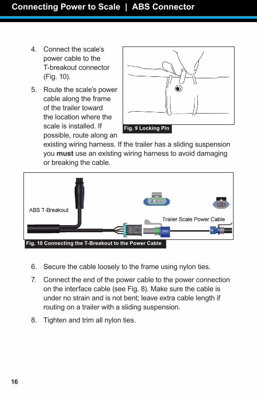
4. Connectthescale’spowercabletotheT-breakoutconnector(Fig.10).
5. Routethescale’spowercablealongtheframeofthetrailertowardthelocationwherethescaleisinstalled.Ifpossible,routealonganexistingwiringharness.Ifthetrailerhasaslidingsuspensionyoumust useanexistingwiringharnesstoavoiddamagingorbreakingthecable.
6. Securethecablelooselytotheframeusingnylonties.
7. Connecttheendofthepowercabletothepowerconnectionontheinterfacecable(seeFig.8).Makesurethecableisundernostrainandisnotbent;leaveextracablelengthifroutingonatrailerwithaslidingsuspension.
8. Tightenandtrimallnylonties.
Connecting Power to Scale | ABS Connector
Fig. 10 Connecting the T-Breakout to the Power Cable
Fig. 9 Locking Pin
Connecting Power to Scale | Junction Box
17
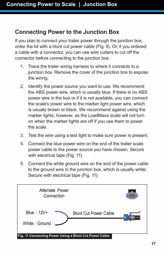
Connecting Power to the Junction BoxIfyouplantoconnectyourtrailerpowerthroughthejunctionbox,orderthekitwithabluntcutpowercable(Fig.9).Or,ifyouorderedacablewithaconnector,youcanusewirecutterstocutofftheconnectorbeforeconnectingtothejunctionbox.
1. Tracethetrailerwiringharnesstowhereitconnectstoajunctionbox.Removethecoverofthejunctionboxtoexposethewiring.
2. Identifythepowersourceyouwanttouse.WerecommendtheABSpowerwire,whichisusuallyblue.IfthereisnoABSpowerwireintheboxorifitisnotavailable,youcanconnectthescale’spowerwiretothemarkerlightpowerwire,whichisusuallybrownorblack.Werecommendagainstusingthemarkerlights,however,astheLoadMaxxscalewillnotturnonwhenthemarkerlightsareoffifyouusethemtopowerthescale.
3. Testthewireusingatestlighttomakesurepowerispresent.
4. Connectthebluepowerwireontheendofthetrailerscalepowercabletothepowersourceyouhavechosen.Securewithelectricaltape(Fig.11).
5. Connectthewhitegroundwireontheendofthepowercabletothegroundwireinthejunctionbox,whichisusuallywhite.Securewithelectricaltape(Fig.11).
Connecting Power to Scale | Junction Box
Fig. 11 Connecting Power Using a Blunt Cut Power Cable

18
Section 6Installing an Alarm
Thepowerinterfacecableprovidedinyourscalekitincludesapowersourceforinstallinganalarm,whichcanbealightoranoise-producingdevice.Toinstallanalarm,followthestepsbelow.
1. Provideanyself-groundedalarmwithacurrentdrawof1.0ampsorless.(Youmustinstallarelayforanyalarmthatdrawsmorethan1.0amps.)
2. Mountthealarminthelocationyouwouldlikeonthetrailerbody.
3. Routethealarm’spowercablealongthebodyofthetrailertothetrailerinterfacecableconnectedtothebackofthescale.
4. Locatethealarmpowerwire(Figs.7and8).Thewireisgrayandsealedontheendwithaplasticcover.
5. Cutofftheplasticcoversothewireisexposed.
6. Connectthewiretothepowercableofthealarmyouprovide.Securewithelectricaltape.
PleaseseetheUserGuide,availableonourwebsiteorfromourSupportteam,forinstructionsoncalibratingyourscale.Yourscalemustbecalibratedbeforeitwilldisplaycorrectweights.
Installing an Alarm Checking for Correct Installation
19
Section 6Checking for Correct Installation
AfteryoufinishinstallingyourLoadMaxxscale,followthestepsbelowtomakesureyouhaveinstalledthescalecorrectly.Thiswillpreventtheenduserfromrunningintoissueswhenusingthescale.
1. Fromthemainmenu,press▼untilthescreenreadsDIAGNOSE.PressENTER.
2. Press▼untilthescreenreadsATODO.PressEnter.Thescreenshouldread“A/D”andshowanumber.ThatnumberisyourA/Dreading.UsethetablebelowtodetermineifyourA/Dreadingisappropriate.
3. Fromyourtractorcab,emptytheheightcontrolvalveonyourtrailerandrefillit.Wait15to30secondsandchecktheA/Dreadingonyourtraileragain.
4. RepeatStep3aboveagain.
5. IftheA/Dreadingsareappropriateinallthreereadings,yourtrailerhasbeeninstalledcorrectly.Iftheyareinaccurate,checkallconnectionsandmakesuretheyaresecurelyattached.Thenchecktheheightcontrolvalvetoseeifitislooseorbroken,whichcancauseinaccurateweightreadings.
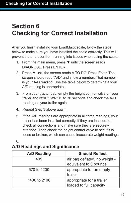
6. A/D Readings and Significance
A/D Reading Should Reflect409 airbagdeflated,noweight-
equivalentto0pounds570to1200 appropriateforanempty
trailer1400to2100 appropriateforatrailer
loadedtofullcapacity
Checking for Correct Installation
20
Limited WarrantyForproductfailuresduetomaterialormanufacturingdefects,Air-Weighwillreplaceorrepairallcomponentsforuptothreeyearsfromshipmentdatetotheend-userAir-Weighcustomer.Thesethree-yearcomponentsinclude:displays,ComLinks,sensors,powercables,sensorassemblies,sensorharnesses,andallotherassociatedexternalcomponents.Air-Weighassumesnoresponsibilityforadministeringwarrantyclaimsdirectlywithanythird-partyendusers.
TheresponsibilityofAir-Weighunderthiswarrantyislimitedtotherepair,replacement,orcreditofthedefectivepartorassembly.
Thiswarrantydoesnotcoverincidentalorconsequentialdamagetopersonsorpropertycausedbyuse,abuse,misuse,orfailuretocomplywithinstallationoroperatinginstructions.Thislimitedwarrantydoesnotapplytoanyproductthathasfailedduetoaccident,abuse,alteration,installationnotconsistentwithprintedinstallationinstructions,impropermaintenance,orimproperoperationorasaresultofsystemintegrationorinstallationnotexplicitlyapprovedinwritingbyAir-Weigh.
Air-WeighanditsresellersshallhavenoresponsibilityorliabilityfordamagesifthepurchaseroranyotherpersonaltersthevehicleincorporatingAir-Weighproducts.ThislimitedwarrantyshallnotapplytoanyproductthathasbeenrepairedoralteredbyanyonenotemployedbyAir-Weighornotoperatedinaccordancewiththemanufacturer’sprintedmaterialdeliveredwiththisproduct.
Air-Weighherebyexpresslydisclaimsanyandallimpliedwarrantiesofanytype,kind,ornaturewhatsoever,andparticularlyanyimpliedwarrantyofmerchantabilityorfitnessforaparticularpurposenotexpresslystatedbyAir-Weighinitsprintedmaterialdeliveredwithitsproducts.Somestatesdonotallowtheexclusionorlimitationofincidentalorconsequentialdamages.Ifsuchlawsapply,thelimitationsorexclusionscontainedinthetermsandconditionsofthiswarrantymaynotapply.Thiswarrantygivesyouspecificlegalrights,andyoumayalsohaveotherrightsthatvaryfromstatetostate.
MaybecoveredbyU.S.PatentNos.5478974,5780782,7478001ForeignPatentNos.260494,677998,2122766
Copyright©2004,2006,2007,2010,2014byHi-TechTransportElectronics,Inc.Allrightsreserved.Air-Weigh®,ComLink™,andHi-TechTransportElectronicsaretrademarksorregisteredtrademarksofHi-TechTransportElectronics,Incorporated.Otherbrand,product,orservicenameslistedinthisdocumentarethetrademarksorregisteredtrademarksoftheirrespectiveholders.Informationcontainedinthisliteraturewasaccurateattimeofpublication.Productchangesmayhavebeenmadeaftercopyrightdatesthatarenotreflectedinthisdocument.
Limited Warranty

21
Procedure For Warranty ClaimsALLcustomersshouldfirstcontactAir-WeighCustomerSupportDepartmentat(888)459-3247forquestionsregardingtheuse,operation,repairorreturnofanyAir-Weighproduct.
IntheeventAir-WeighrequeststoexaminetheproductpriortodispositionORforrepairorreplacement,Air-WeighrequiresaReturnMaterialAuthorization(RMA)numberbeissuedbeforetheitemisreturned.CustomerSupportwillissuetheRMAnumber.PleasereferencethisRMAnumberinallcorrespondence.
Claimeditemsshallbeshippedfreightpre-paidto:Air-Weigh CustomerSupportDepartment 1720WillowCreekCircle,Suite510 Eugene,Oregon97402,USA
TheAir-WeighRMAnumbermustappearontheoutsideofthereturnpackaging.Air-Weighshallexaminereturnedmaterialwithin30daysafterreceipt,orsoonerifmutuallyagreedupon.IfAir-Weighdeterminesthatthepartorassemblywasdefectiveinmaterialorworkmanshipandwithinthewarrantyperiod,Air-Weighwillrepairorreplacethepartorassemblyandreturnfreightpre-paid.IntheeventAir-Weighdeterminesthatthepartorassemblycannotberepairedorreplacedandiswithinthewarrantyperiod,acreditnottoexceedthepurchasepricewillbeissuedtotheAir-Weighcustomer.
ForourcustomersusingpurchaseordersAir-Weighwillprocessacreditmemoandnotifythecustomerbyemailorfax.ThecustomerwillprocessacorrespondingdebitmemoandnotifyAir-Weighaccordingly.
IfthepartorassemblyreceivedbyAir-Weighdoesnotmeettherequirementsofthewarrantyprogramsetforthabove,attheAir-Weighcustomer’srequestthepartorassemblywilleitherbediscarded,returnedfreightcollect,orrepairedorreplacedattheAir-Weighcustomer’sexpenseandreturnedfreightcollect.
Procedure for Warranty Claims

1730WillowCreekCircle•Eugene,OR97402-9152USAP.O.Box24308•Eugene,OR97402-0437USA
Telephone(541)343-7884•OrderDesk(888)459-3444CustomerSupport(888)459-3247•Fax(541)431-3121
HoursofOperation:Monday-Friday,7a.m.-5p.m.,PSTwww.Air-Weigh.com


