
ssl.energy.gov eere.energy.gov0
LED Dimming: What you need to know
DOE SSL Program Michael Poplawski
Pacific Northwest National Laboratory [email protected]
December 10, 2012

Why dim LED sources?
• Additional energy savings • Increased visual task performance • Enhanced ambience • Fewer light sources to specify, maintain, stock • Enhanced space flexibility, satisfaction • Demand response load shedding • Potentially improved light source efficacy, lifetime
ssl.energy.gov eere.energy.gov 1

What’s the big deal?
• Dimming LED sources in the real world can be challenging, particularly with phase-cut dimmers
• Wide variation in LED source and dimmer characteristics
• Little can be assumed • Not all claims are equal • Difficult to predict
ssl.energy.gov eere.energy.gov 2

What you need to know
• LEDs are inherently dimmable • LEDs typically need a “Driver” • Dimming an LED source can change the behavior of the
Driver • LED dimming performance is determined by Driver
capability and compatibility with the dimming equipment • Multiple compatibility issues are rooted in circuit level
interactions between the LED Driver and dimmer • What you think you know may no longer be valid
ssl.energy.gov eere.energy.gov 3

You can dim today, if you want to
• Good LED dimming solutions are available today – with various trade-offs – new standards, technologies in development – user experiences should improve in future
• Chances for success correlated with willingness, ability to learn new things – unfamiliar issues – new standards, technologies
• Chances for success also correlated with willingness, ability to evaluate products first hand – not new guidance – color rendering, glare, etc.
ssl.energy.gov eere.energy.gov 4

What you need to figure out
• What your options are • Where information and guidance is available • What questions to ask • What potential trade-offs are important, or not important
to your application • What your risk tolerance is • How much you are willing to learn
ssl.energy.gov eere.energy.gov 5

Controlling current in simple (resistive) loads
• Resistive loads have linear current-voltage relationships – I = (1/R) x V 100
75– For AC input, only care about Vrms 50
– Time independency: Irms = (1/R) x Vrms 25 0
Irms
0 1 2 3 4 Vrms
• Resistive loads are bidirectional – Applying ±Vrms results in the same Irms – Irms = (1/R) x |Vrms|
+Vrms
Irms Irms
+Vrms
ssl.energy.gov eere.energy.gov 6

+Vrms
Irms
Incandescent sources are simple (resistive) loads
• Incandescent sources electrically behave like resistors (unlike pretty much every other lighting technology)
• Incandescent sources effectively only care about Vrms – Constant R at steady state – R is a function of filament temperature
• Incandescent sources are bidirectional – Applying ±Vrms results in the same Irms Irms – Irms = (1/R) x |Vrms|
• Important caveat: thermal persistence +Vrms – If I(t>0)0 in resistor, no power consumption – If I(t>0)0 in incandescent source, light output continues as long
as filament is hot (10s to 100s of milliseconds)
ssl.energy.gov eere.energy.gov 7

Controlling current in complex loads
• Complex loads contain complex electronic devices (e.g. capacitors, inductors)
• Complex loads contain devices which store energy • Complex loads contain devices with non-linear current-
voltage relationships • Complex loads contain devices with time-dependencies
(e.g. dv/dt, di/dt, on/off switching)
Capacitors store Inductors store energy energy in electric fields in magnetic fields
ssl.energy.gov eere.energy.gov 8

Vled
LEDs are complex loads
• LEDs are non-linear devices – Different current-voltage relationships in
different regions of operation
– Small change in voltage can equal large change in current
– (Average) current must (typically) be controlled
• LEDs are unidirectional – (Forward) current only flows in one direction +Vled>Vth
– Light output only for forward current I≈0Iled• Important caveat: fast response
– If I(t>0)0 in diode, no power consumption +Vled>Vth
– If I(t>0)0 in LED, no light output – Careful attention to time where I≈0
I led
ssl.energy.gov eere.energy.gov 9

Black Box
LEDs (typically) need a “Driver”
Vrms = 120V CCAC
Power Black Box
• Non-linear Iled vs. Vled relationship, together with manufacturing variation in Vf, mean LEDs are best regulated by controlling their current
• Typically, LEDs are operated (or “Driven”) such that their (average) current is constant (Constant Current)
• Typically, power electronics components are used to create circuits which convert AC voltage into regulated LED constant (average) current
ssl.energy.gov eere.energy.gov 10

LED’s are dimmable
Constant Current Reduction Also known as CCR, Analog • Varying LED current, LED
always on • Longer LED lifetime
– Lower current and temperature • No noise generation • Potentially higher efficacy at
lower dimming (lower current) levels
• Does not create flicker • Objectionable color shift? • More difficult dimming
regulation at deep dimming (low current) levels
100%60%
100%60%R
elat
ive
Lum
inou
s Fl
uxR
elat
ive
Lum
inou
s E
ffica
cy
(Average) Forward Current (mA)
(Average) Forward Current (mA)
ssl.energy.gov eere.energy.gov 11

LED’s are dimmable
Pulse Width Modulation • Same LED current, varying
LED on/off (typically) times • Longer LED lifetime
– Less LED on time, lower temperature
• Good dimming regulation at deep dimming (same current) levels
• No color shift? • Potential noise generation • PWM frequency is important
– Potentially undesirable flicker – Minimum dimming level
100
80
60
40
20
0
100
80
60
40
20
0
Also known as PWM
50% PWM 1/Frequency
Average Level 50% 50%
0 5 10 15 20 25 Time (mS)
25% PWM 1/Frequency
25% 75%
Average Level
0 5 10 15 20 25 Time (mS)
ssl.energy.gov eere.energy.gov 12

Dimming technologies
Dimmer
AC Power
Hot
Neutral
Dimmed Hot Switched Hot (power)
Dimmed Hot (signal)AC Power
Hot
Neutra l
Phase-Cut Fluorescent 3-Wire
Switched Hot (power)
0-10V +/AC Power
Hot
Neutral
DALI +/AC Power
Hot
Neutral
0-10V DALI
ssl.energy.gov eere.energy.gov 13
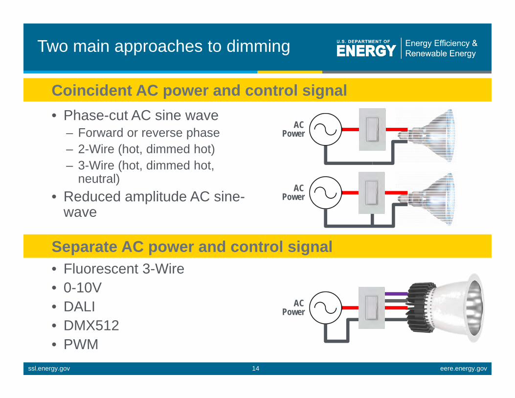
Two main approaches to dimming
Coincident AC power and control signal • Phase-cut AC sine wave
AC – Forward or reverse phase Power
– 2-Wire (hot, dimmed hot) – 3-Wire (hot, dimmed hot,
neutral) AC
• Reduced amplitude AC sine- Power
wave
Separate AC power and control signal • Fluorescent 3-Wire • 0-10V
AC• DALI Power • DMX512 • PWM
ssl.energy.gov eere.energy.gov 14
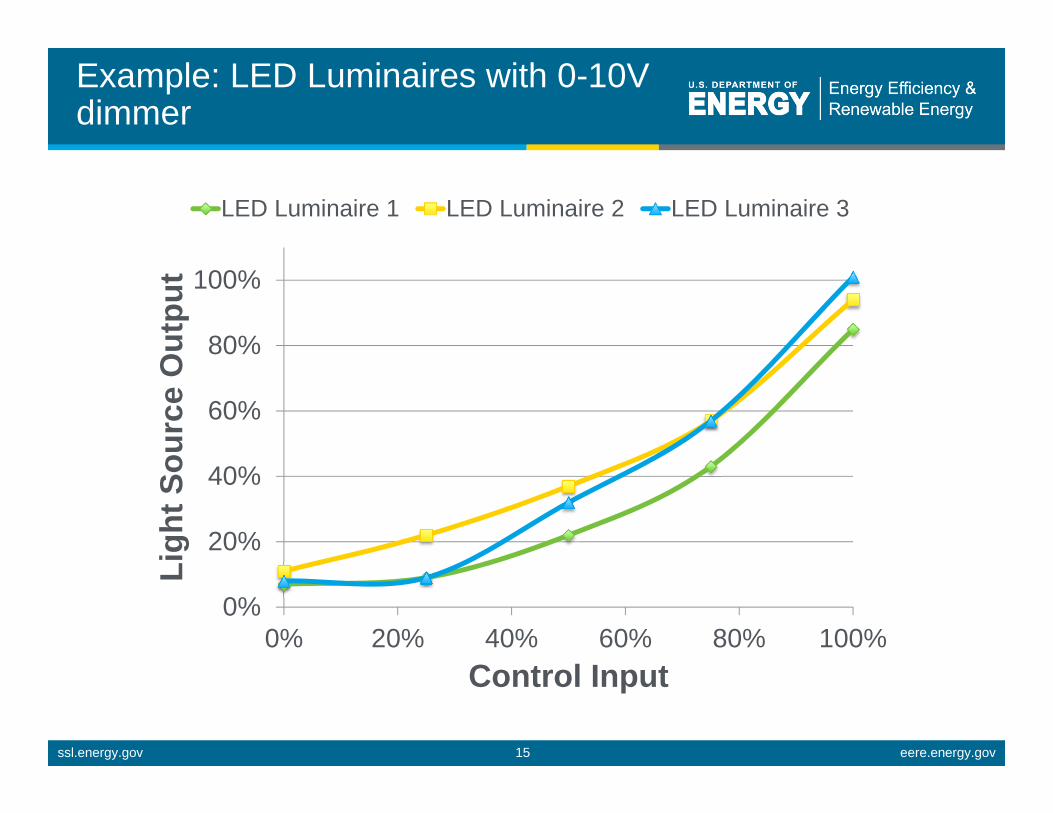
Example: LED Luminaires with 0-10Vdimmer
LED Luminaire 1 LED Luminaire 2 LED Luminaire 3
0% 20% 40% 60% 80% 100%
Ligh
t Sou
rce
Out
put 100%
80%
60%
40%
20%
0%
Control Input
ssl.energy.gov eere.energy.gov 15

LED luminaire 1 + 0-10V dimmer A
~50% dimmer ~25% dimmer ~0% dimmer
Switch 100% dimmer ~75% dimmer
ssl.energy.gov eere.energy.gov 16

LED luminaire 2 + 0-10V dimmer A
Switch
~50% dimmer ~25% dimmer ~0% dimmer
100% dimmer ~75% dimmer
ssl.energy.gov eere.energy.gov 17
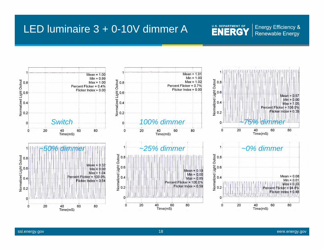
LED luminaire 3 + 0-10V dimmer A
~50% dimmer ~25% dimmer ~0% dimmer
Switch 100% dimmer ~75% dimmer
ssl.energy.gov eere.energy.gov 18
Sidebar: What is flicker?
• Variation in time (modulation) of light output (luminous flux)
• Present in all traditional commercial electric light sources running on AC power – Including incandescent, halogen, fluorescent, metal-halide – Typically (but not always) periodic, and property of light source – Whether you are aware of it or not
• Not to be confused with electrical flicker – Noise on AC distribution line directly creates additional (light)
modulation on resistive (incandescent) loads
– Not a property of the light source
• Measurement and reporting is not a standard practice for commercially available light sources
ssl.energy.gov eere.energy.gov 19

Sidebar: Who cares about flicker?
• Anyone who is sensitive • Anyone responsible for human health, well-being and/or
performance in spaces with electric lighting • At-risk populations for specific impairments
– Photosensitive epileptics: 1 in 4000 – Migraine sufferers – Not all at-risk populations identified
• Young people • Autistic people
ssl.energy.gov eere.energy.gov 20
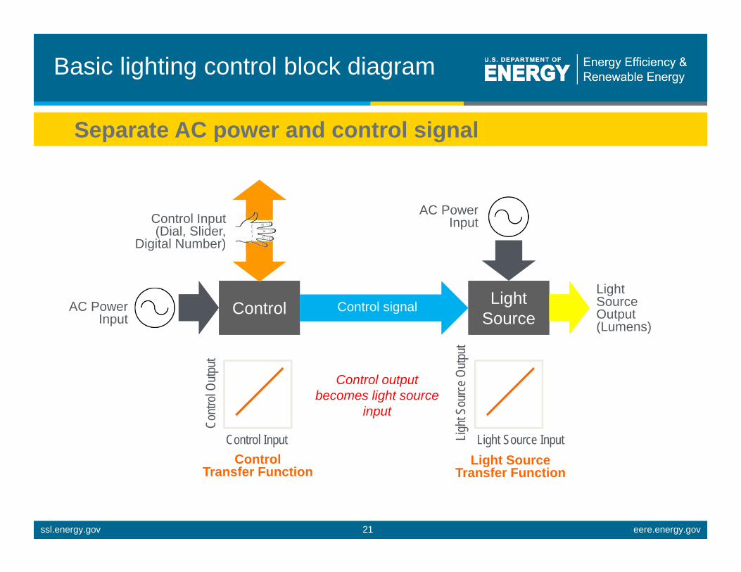
Light SourceControl
Basic lighting control block diagram
Separate AC power and control signal
AC PowerControl Input Input(Dial, Slider, Digital Number)
Light SourceControl Control signal
LightSource Output(Lumens)
AC Power Input
Contr
ol Ou
tput
Control Input
Control output becomes light source
input
Light
Sour
ce O
utput
Light Source Input Control Light Source
Transfer Function Transfer Function
ssl.energy.gov eere.energy.gov 21

Common control transfer functions
Linear Square S
120%
Con
trol
Out
put 100%
80%
60%
40%
20%
0%
Control Input 0% 20% 40% 60% 80% 100%
ssl.energy.gov eere.energy.gov 22

Different dimmer manufacturers target different transfer functions
Manufacturer A Manufacturer B Manufacturer C Linear Square S
0-10
V C
ontr
ol O
utpu
t 12
10
8
6
4
2
0
0-10V Control Input 0% 20% 40% 60% 80% 100%
ssl.energy.gov eere.energy.gov 23

Different LED source manufacturers target different transfer functions
Ligh
t Sou
rce
Out
put
Manufacturer A (Square) Manufacturer B (Linear)
100%
80%
60%
40%
20%
0%
0-10V Light Source Input 0 1 2 3 4 5 6 7 8 9 10
ssl.energy.gov eere.energy.gov 24

Sometimes this works
Square Control + Linear Light Source Li
ght S
ourc
e O
utpu
t
100%
80%
60%
40%
20%
0% 0% 20% 40% 60% 80% 100%
Control Input
ssl.energy.gov eere.energy.gov 25

Sometimes this doesn’t work
Square Control + Square Light Source Li
ght S
ourc
e O
utpu
t
100%
80%
60%
40%
20%
0% 0% 20% 40% 60% 80% 100%
Control Input
ssl.energy.gov eere.energy.gov 26
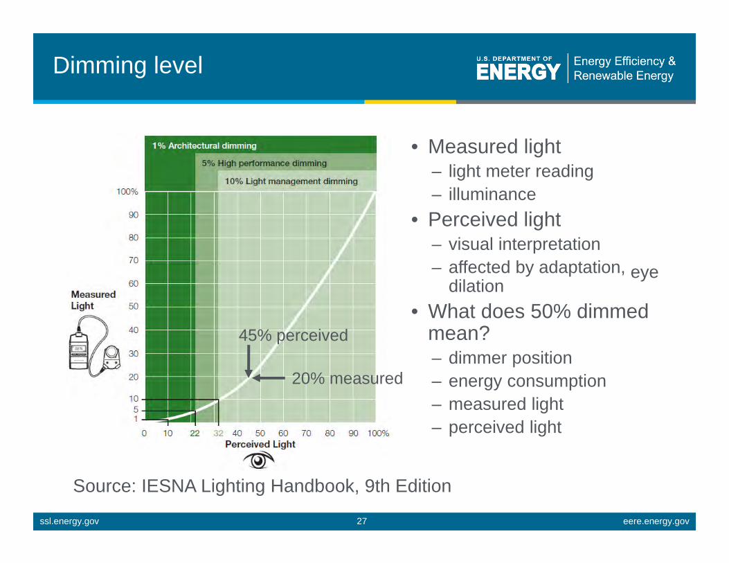
Dimming level
• Measured light – light meter reading – illuminance
• Perceived light – visual interpretation – affected by adaptation, eye
dilation • What does 50% dimmed
mean? – dimmer position – energy consumption – measured light – perceived light
20% measured
45% perceived
Source: IESNA Lighting Handbook, 9th Edition
ssl.energy.gov eere.energy.gov 27
A word about power quality
• Dimming an LED source can change the behavior of the Driver – Efficiency can degrade, but may be offset by improving LED
efficacy
– Flicker can be induced or increased – Power quality, as quantitatively evaluated by the Power Factor and
Total Harmonic Distortion metrics, can be degraded
• LED Drivers typically can not maintain consistent performance over a wide range of conditions – Temperature – Connected load – Input voltage
• LED Driver performance varies with technology, cost
ssl.energy.gov eere.energy.gov 28
Sidebar: What is power quality?
• Displacements anddistortions to voltage and current waveforms
• Metrics – Power Factor – Total Harmonic Distortion
• Power Factor relates Active Power (P) andApparent Power (S) by PF = P/S
• Low(er) power factor loads DO NOT consume more energy, BUT they DO draw more RMS current
• Total Harmonic Distortion (THD) – THD-V – THD-I
• Voltage waveform distortions typically created by generators
• Current waveform distortions typically created by loads
• Common standard for generators is to limit THD-V < 5%
• Common specification for loads it to limit THD-I < 20%
ssl.energy.gov eere.energy.gov 29

Sidebar: Who cares about power quality?
Electricity producers and consumers • Increased current
requirements – Electricity transport (I2R)
losses (<10%) – Wire, circuit breaker,
transformer, etc. sizing – System issue; hard to
quantify
• Can in some cases lead to electronic equipmentdamage, degradedperformance
Lighting equipmentmanufacturers • Voluntary requirements for
lighting equipment in ANSI C82.77-2002 – Most recent published
version – Revision under development
• System design tradeoffs for some LED sources
• Cost and size constraints for some LED sources
ssl.energy.gov eere.energy.gov 30

Light SourceControl
What about incandescent dimming?
Coincident AC power and control signal • Phase-cut AC sine wave
AC – Forward or reverse phase Power – 2-Wire (hot, dimmed hot) – 3-Wire (hot, dimmed hot,
neutral) AC Power• Reduced amplitude AC sine-
wave
Control Input(Dial, Slider,
Digital Number)
Light SourceControl Coincident AC power
and control signal
LightSourceAC Power OutputInput (Lumens)
ssl.energy.gov eere.energy.gov 31

Phase-cut vs. Sine-wave dimming
• Phase-cut control is the most commonly deployed dimming technology
• Large U.S. installed base – NEMA estimates >150M – Mostly “analog” (no neutral)
Phase-Cut Dimmer Sine-Wave Dimmer
ssl.energy.gov eere.energy.gov 32

Phase-cut dimming was designed for incandescent sources
Vrms = 120V
Vrms = 120V
Vrms = 120V
Vrms = 120V
Same (average) light
output
Vrms = 120V Vrms = 60V
High performance Inexpensive Vrms adjuster Determines dimming performance
50% light output
ssl.energy.gov eere.energy.gov 33

Example: Incandescent source +phase-cut dimmers
Similar dimming range, different dimming curves
ssl.energy.gov eere.energy.gov 34

Example: Incandescent source +phase-cut dimmers
Reduced efficacy when dimmed
ssl.energy.gov eere.energy.gov 35

Black Box
Phase-cut dimming of LED light sources
Different (average)
light output
Black Box
Vrms = 120V
Vrms = 120V
Vrms = 120V
Vrms = 120V
Vrms = 120V Vrms = 60V
High performance Controls current to LED Inexpensive Capability, compatibility Vrms adjuster determines dimming
performance ssl.energy.gov eere.energy.gov 36

Example: LED source + phase-cutdimmers
Varying dimming ranges and curves
ssl.energy.gov eere.energy.gov 37

Example: LED source + phase-cutdimmers
Maintains efficacy when dimmed
ssl.energy.gov eere.energy.gov 38

Example: LED lamp 1 + phase-cutdimmer A
Switch 100% dimmer ~75% dimmer
~50% dimmer ~25% dimmer ~0% dimmer
ssl.energy.gov eere.energy.gov 39

ssl.energy.gov eere.energy.gov 40
Example: LED lamp 1 + phase-cutdimmer B
~50% dimmer ~25% dimmer ~0% dimmer
Switch 100% dimmer ~75% dimmer

What’s the big deal, again?
• Dimming LED sources in the real world can be challenging, particularly with phase-cut dimmers
• Wide variation in LED source and dimmer characteristics
• Little can be assumed • Not all claims are equal • Difficult to predict
• Performance – Dimming range, curve – Efficacy – Flicker – Power quality
• Compatibility – Dead travel – Popcorn – Flashing, Ghosting – Pop-on, Drop-out – Audible noise – Inoperability – Premature failure
ssl.energy.gov eere.energy.gov 41

Phase-cut dimming challenges
• The behavior of an LED source on a circuit controlled by a phase-cut dimmer is a function of: 1. the characteristics of the LED source (driver) 2. the number and type of light sources on the circuit 3. the characteristics of the dimmer
• Many types of behavior variation • Many sources of behavior variation • Behavior variation spans compatibility, performance,
interoperability • Behavior variation is significant in magnitude • Behavior is only predictable via circuit level testing • Currently no standard definitions or test procedures for
evaluating dimming behavior ssl.energy.gov eere.energy.gov 42
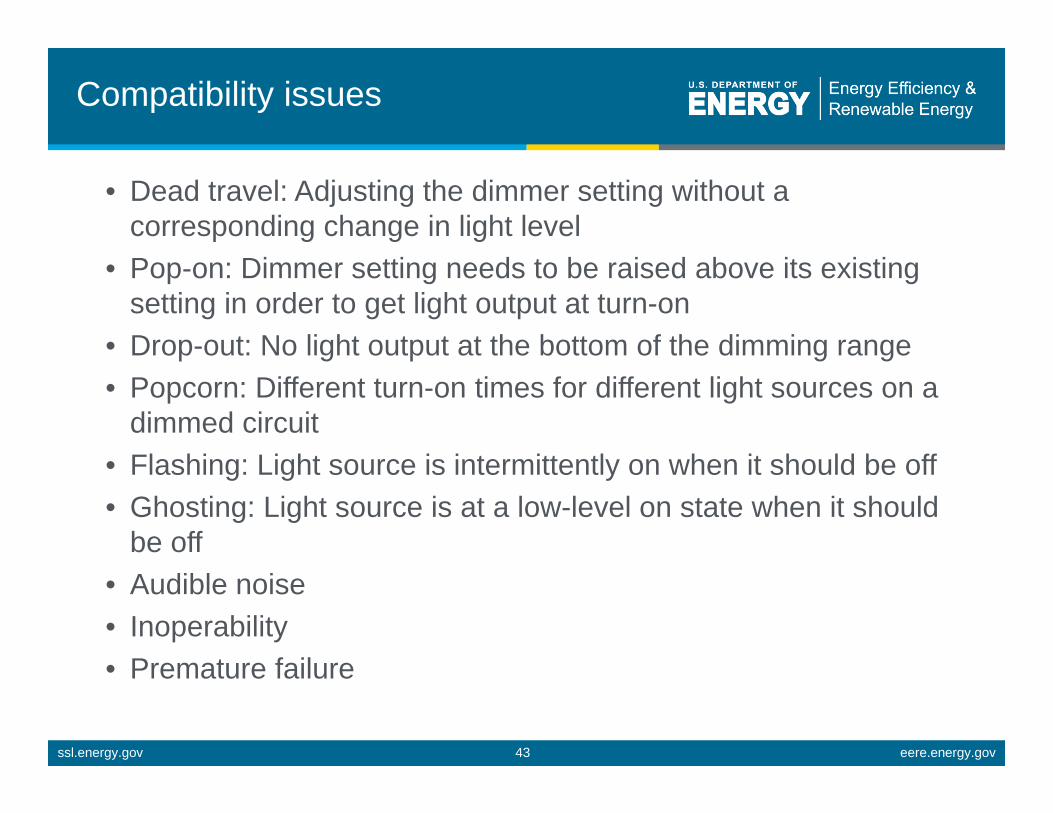
Compatibility issues
• Dead travel: Adjusting the dimmer setting without a corresponding change in light level
• Pop-on: Dimmer setting needs to be raised above its existing setting in order to get light output at turn-on
• Drop-out: No light output at the bottom of the dimming range • Popcorn: Different turn-on times for different light sources on a
dimmed circuit • Flashing: Light source is intermittently on when it should be off • Ghosting: Light source is at a low-level on state when it should
be off • Audible noise • Inoperability • Premature failure
ssl.energy.gov eere.energy.gov 43
ssl.energy.gov eere.energy.gov 44
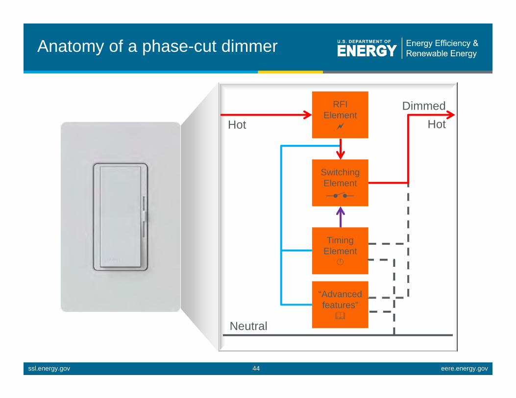
Anatomy of a phase-cut dimmer
“Advanced features”
RFI Element
Timing Element
Switching Element
Hot Dimmed
Hot
Neutral

Sources of phase-cut dimmingcompatibility issues
• LED load can not measure VRMS and/or conduction angle presented by the dimmer
• LED load does not draw enough current to keep dimmer switching element(s) closed, leading to erratic behavior
• LED load creates a series impedance which disrupt dimmer timing element(s), leading to erratic behavior
• LED load in off state does not pass dimmer current in a manner which keeps dimmer advanced features functioning while remaining in off state
• LED load draws currents which create stresses on dimmer above and beyond what its rated (incandescent) wattage indicates, leading to reduced dimmer lifetime
ssl.energy.gov eere.energy.gov 45
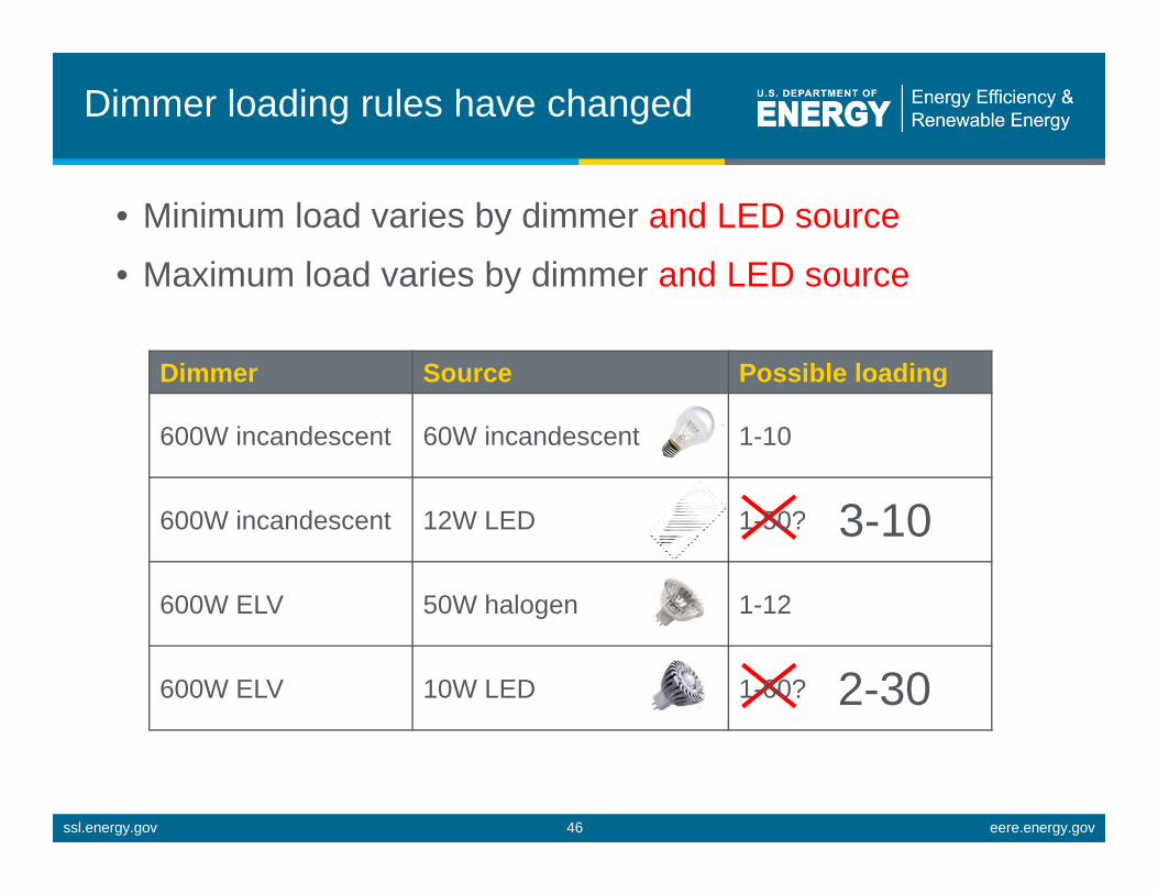
Dimmer loading rules have changed
• Minimum load varies by dimmer and LED source
• Maximum load varies by dimmer and LED source
Dimmer Source Possible loading
600W incandescent 60W incandescent 1-10
600W incandescent 12W LED 1-50? 3-10 600W ELV 50W halogen 1-12
600W ELV 10W LED 1-60? 2-30
ssl.energy.gov eere.energy.gov 46

Review: What’s the big deal?
• Dimming LED sources in the real world can be challenging, particularly with phase-cut dimmers
• Wide variation in LED source and dimmer characteristics leads to wide variation in dimming performance and compatibility
• Little can be assumed, as historical practices are unreliable – “600W maximum load”, technology and model independent – “works with ELV dimmers”
• Not all claims are equal, given lack of standard criteria • Difficult to predict, given lack of standard test procedures
ssl.energy.gov eere.energy.gov 47

Review: What you need to know
• LEDs are inherently dimmable • LEDs typically need a “Driver” • Dimming an LED source can change the behavior of the
driver – Source efficacy typically maintained during dimming – Dimming can induce or increase flicker – Dimming can degrade power quality
• LED dimming performance is determined by Driver capability and compatibility with the dimming equipment
• Multiple compatibility issues are rooted in circuit level interactions between the LED Driver and dimmer
• What you think you know may not longer be valid
ssl.energy.gov eere.energy.gov 48
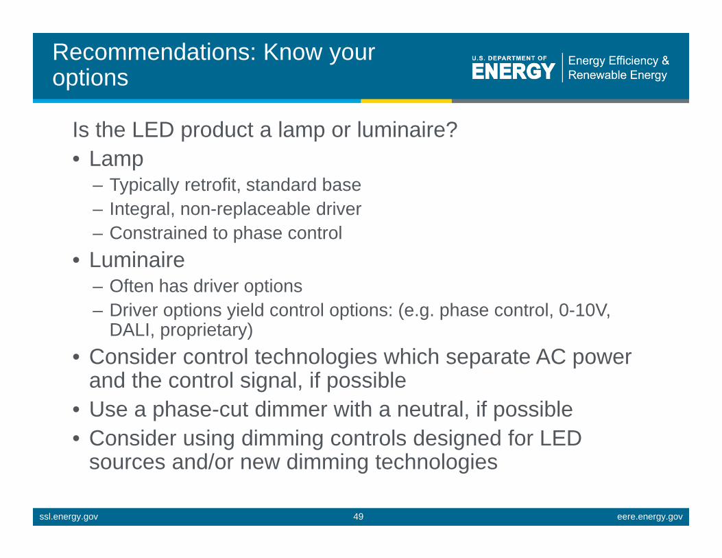
Recommendations: Know youroptions
Is the LED product a lamp or luminaire? • Lamp
– Typically retrofit, standard base – Integral, non-replaceable driver – Constrained to phase control
• Luminaire – Often has driver options – Driver options yield control options: (e.g. phase control, 0-10V,
DALI, proprietary) • Consider control technologies which separate AC power
and the control signal, if possible • Use a phase-cut dimmer with a neutral, if possible • Consider using dimming controls designed for LED
sources and/or new dimming technologies
ssl.energy.gov eere.energy.gov 49

Recommendations: take advantageof available information and guidance
• What is the designed, claimed, (i.e. best-case) dimming performance of the LED source? – Dimming range (max – min) – Assumptions, requirements
• Is there a recommended dimming control selection guidance? – If so, definitely use it – Specific makes/models; control type (i.e. forward or reverse phase)
is likely not sufficient – Dimmer loading requirements (i.e. max/min number of LED
sources per control) – Beware expectations of exactly the same performance from any/all
guidance
ssl.energy.gov eere.energy.gov 50

ssl.energy.gov eere.energy.gov 51
Dimmer manufacturer guidance

ssl.energy.gov eere.energy.gov 52
Lamp manufacturer guidance

Recommendations: Ask for “standard” dimming guidance
Dimming information reporting format
Dimmer Make
Dimmer Series ‐Model
Dimmer Trim Requirements
Transformer Make
(low voltage lamps)
Transformer Model
(low voltage lamps)
LED Lamp or Luminaire
Series ‐Model
Dimming Range, max‐min (% lumens)
Minimum Lamps or Luminaires (per circuit)
Maximum Lamps or Luminaires (per circuit)
Additional Comments
"PAR38 Series" ‐"PAR38ABC123"
99% ‐ 0% 1 6"Dimmer Make 1"
"Dimmer Series A" ‐ "Dimmer Model #"
Low End N/A N/A "PAR38 Series" ‐"PAR38XYZ456"
"PAR38 Series" ‐"PAR38EFG789"
"Dimmer Make 2"
"Dimmer Series A" ‐ "Dimmer Model #"
N/A "Transformer Make 1"
"Transformer Model #"
"Brand Y MR16s" ‐"MR16ABC123" 100% ‐ 5% 1 40
"Brand Y MR16s" ‐"MR16ABC123" 1 3
"Dimmer Make 2"
"Dimmer Series B" ‐ "Dimmer Model #"
N/A "Transformer Make 1"
"Transformer Model #" 100% ‐ 5%
"MR16ABC123" + 1
"MR16XYZ456"
"MR16ABC123" + 10
"MR16XYZ456" "Brand Y MR16s" ‐"MR16XYZ456"
ssl.energy.gov eere.energy.gov 53
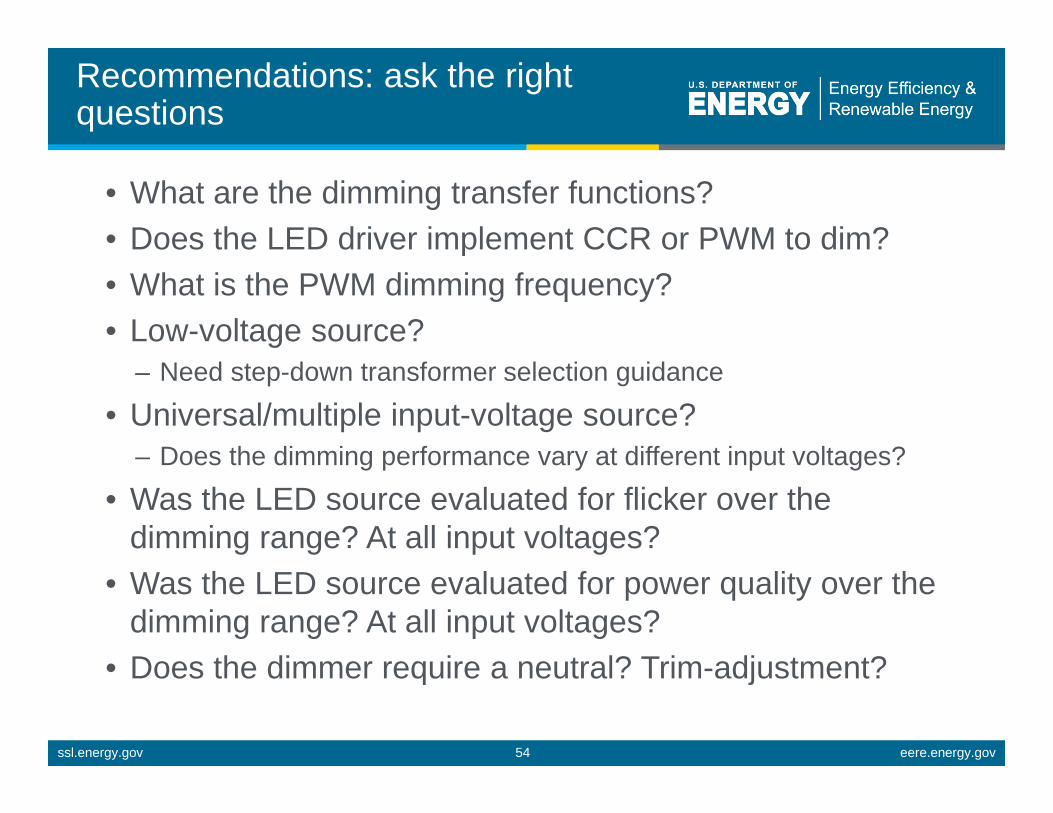
Recommendations: ask the right questions
• What are the dimming transfer functions? • Does the LED driver implement CCR or PWM to dim? • What is the PWM dimming frequency? • Low-voltage source?
– Need step-down transformer selection guidance
• Universal/multiple input-voltage source? – Does the dimming performance vary at different input voltages?
• Was the LED source evaluated for flicker over the dimming range? At all input voltages?
• Was the LED source evaluated for power quality over the dimming range? At all input voltages?
• Does the dimmer require a neutral? Trim-adjustment?
ssl.energy.gov eere.energy.gov 54

Recommendations: weight the tradeoffs
• Application needs vs. wants – How much does flicker matter? – How much does power quality matter?
• Option 1: Only use LED sources and phase-cut dimming controls with defined compatibility and performance – Manufacturer guidance – Standards
• Option 2: Mock up installations – All LED sources, all dimmers – All source combinations – Yes, this means full circuits – Beware SSL source or dimmer substitutions, model updates
ssl.energy.gov eere.energy.gov 55

Recommendations: analyze risk
• Common “fixes” – Change the LED source, LED driver, or dimming control – Add incandescent or dummy loads – Add neutral wires
• Often there are no good solutions once products are installed
• Who is responsible? Who pays? • Have a plan BEFORE products are ordered and installed
ssl.energy.gov eere.energy.gov 56
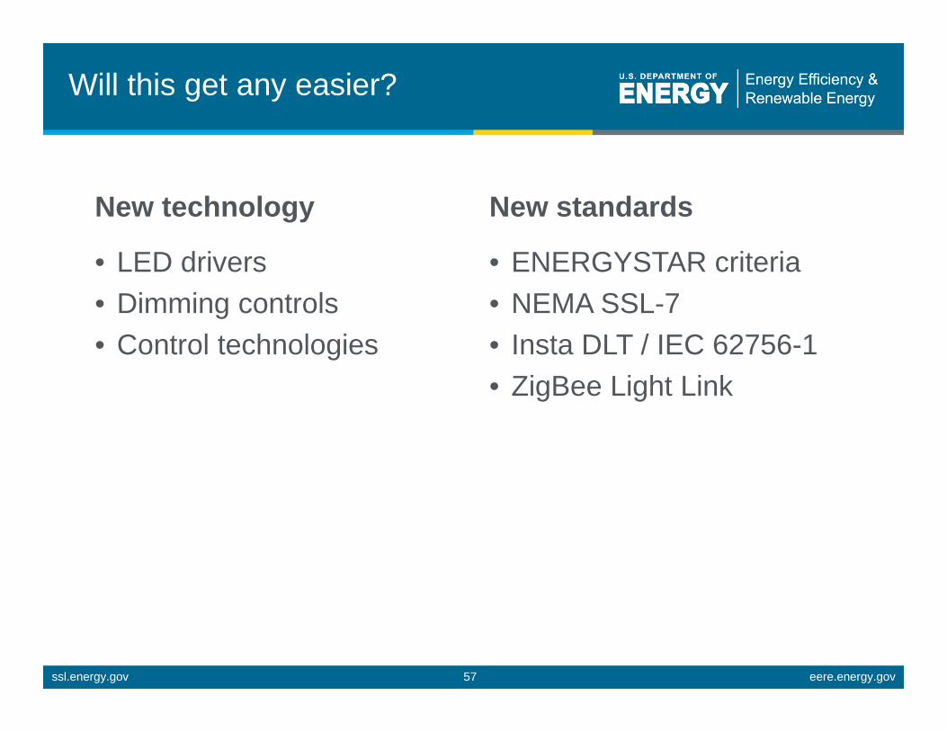
Will this get any easier?
New technology New standards
• LED drivers • ENERGYSTAR criteria • Dimming controls • NEMA SSL-7 • Control technologies • Insta DLT / IEC 62756-1
• ZigBee Light Link
ssl.energy.gov eere.energy.gov 57

New LED drivers
• Embedded intelligence “detects” dimmer characteristics
• Could lead to (near) universal compatibility?
New, Improved Design
ssl.energy.gov eere.energy.gov 58
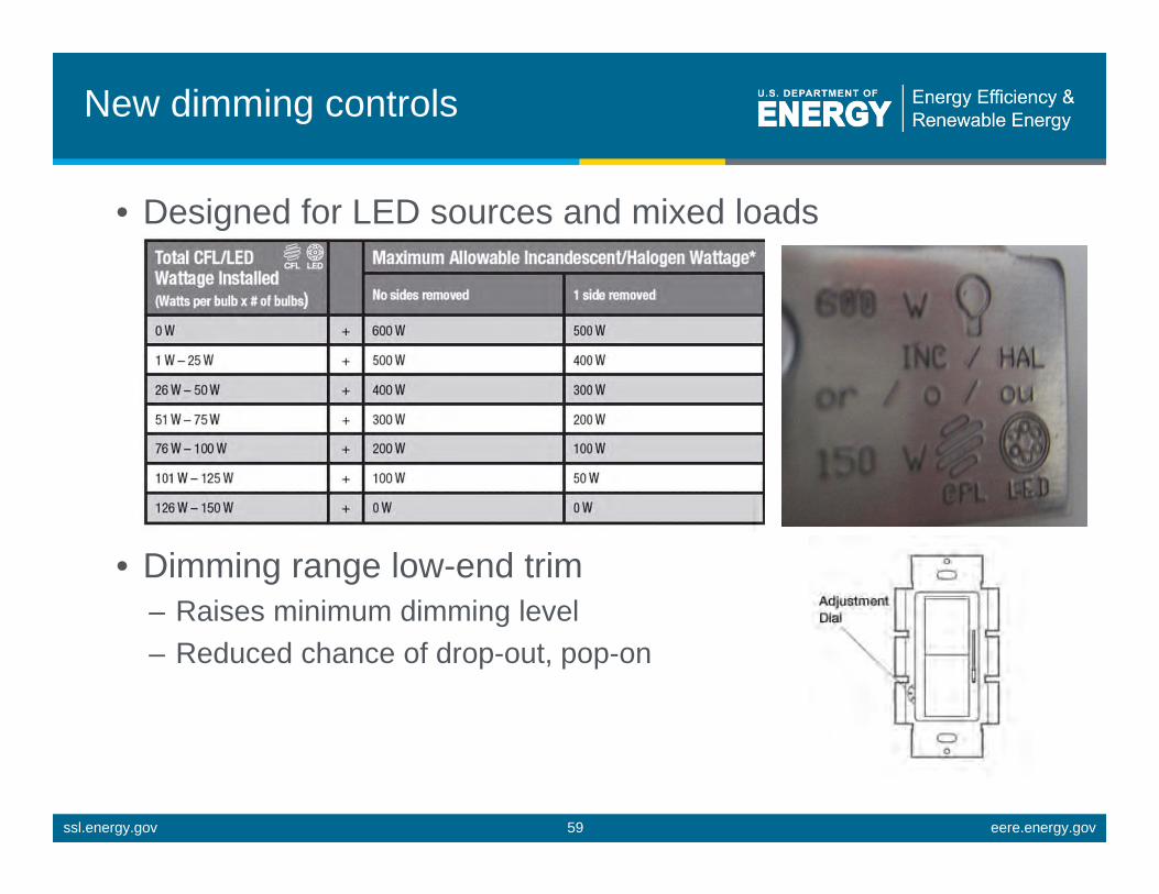
New dimming controls
• Designed for LED sources and mixed loads
• Dimming range low-end trim – Raises minimum dimming level – Reduced chance of drop-out, pop-on
ssl.energy.gov eere.energy.gov 59

New control technologies
• Powerline carrier – Digital modulation of AC
power – Coincident AC power and
control signal • Wireless
– Digital open spectrum communication
– Separate AC power and control signal
• Centralized power supply or LED driver – Low-voltage (CV or CC)
wiring to LED source – Coincident or separate AC
power and control signal
Wi-Fi Router Lighting Gateway
Lighting App
Connected Lamps
Remote
ssl.energy.gov eere.energy.gov 60

NEMA SSL-7
• SSL-7A (compatibility): in development; ETA early 2013
• SSL-7B (performance): initiated upon completion of 7A • Defined compatibility and performance for SSL-7
compliant phase-cut controls and lamps/luminaires – Current scope covers forward phase-cut controls only – Current scope covers light sources which connect to electrical
branch circuit, and have electronic power supply
• Defines design specifications for lamps/luminaires and phase-cut controls
• Defines compliance test procedures for lamps/luminaires and phase-cut controls
ssl.energy.gov eere.energy.gov 61

ZigBee Light Link
• Requires new control and LED driver
• Low-cost (leverages other Zigbee applications)
• Wire-free installation, retrofit • Device authentication, AES
128 encryption • Easy to assign
single/individual control devices to one or many light sources (without added wiring)
• Certification ensures compliance, and thereby compatibility
ssl.energy.gov eere.energy.gov 62

ssl.energy.gov eere.energy.gov63
Questions? [email protected]
DOE SSL Program Michael Poplawski
Pacific Northwest National Laboratory [email protected]
December 10, 2012


