
Ch 1 - Ch 10
Overview
Features
Lighting control module
EBR-LCM8, EBR-LCM10 & EBR-LCM12
Wiring compartment Within the wiring compartment there are the following connections.
• Mains, including a Permanent Live used to feed the emergency test relay.
• Low Voltage connections
• 6 x SELV inputs
• 2 x Rapid network CAN ports
• Shared 6A emergency test relay.
Emergency test relay Shared 6A relay via each GST style output
Pluggable connections 8, 10 or 12 outputs via a GST style switched ports with either separate broadcast DALI / DSI broadcast or 1-10V connections.
Volt free output port (EBR-LCM10-10AD and EBR-LCM10-10DD only)
6A 230VAC Voltage free contact. Used to switch external peripherals, such as HVAC and BMS systems.
RJ45 ports At the end of the unit there are 5 RJ45 ports.
• 2 x power and Rapid network CAN ports
• 2 x Rapid network CAN ports
• 1 x SELV switch input port (7 inputs plus common)
Removable memory feature The removable memory feature allows settings to be easily transferred to a replacement or new LCM without the need for reprogramming.
Front features (10 output LCM shown)
Wiring compartment
Product Guide
Volt free output port
RJ45 ports Programming window which covers...
IR Receiver IR Transmitter
Status LEDs
The EBR-LCM8, EBR-LCM10 & EBR-LCM12 series of lighting control modules (LCMs) are used as part of the Rapid lighting control system to control lighting. The standard Rapid LCM has 8 individually addressable outputs to allow for fully independent control of DALI/DSI or switching only fittings. The Rapid LCM can be expanded using a 4 output plug in module, providing an extra four 6 pole outputs. All LCMs are available with CP’s patented Energy Measurement technology as an option for measuring the energy consumption of all luminaires connected to the LCM. A separate relay is used for emergency testing. This LCM also has a total of 11 SELV switch inputs. 6 in the wiring compartment with screw terminals and 7 via an RJ45 port. The plug in module is available in a number of formats which allow the installer to incorporate a different dimming protocol from the main LCM and also a volt free contact for switching fixed output loads like fan coil units. The ability to have a different dimming protocol from the main LCM is also useful where, during the fit out, LED lighting may have been installed which is 1-10v and where an existing LCM is either DALI or DSI. The 4 outputs are also individually addressable allowing for maximum flexibility.

2
Installation
Installation System wiring example
Rapid PIR
Rapid Scene plates
Standard light switches
2 core SELV for momentary push switch. 3 core SELV for centre biased retractive switch. Legrand part no. 7354 14
Rapid Microwave
DALI light fittings
CAT 5 cable
EBR-LCM10-10DD
Channel for channel nuts (zebs) Removable gland plate with 3 x Ø20mm knockouts
3 x Ø20mm knockouts for
rear cable entry
6 x key slots to accept M6 (1/4”) fixings
BESA box fixings
Warning. This device works at mains voltage. Be sure to take care when working with electricity.
• The box should be fixed on a smooth, flat surface or using drop rod fixings attached to channel nuts.
• Ensure that there is easy access to the wiring compartment and all connectors once the box is in-situ.
• Care should be taken when siting the LCM to ensure that other services or building fabric do not obstruct access to the IR port and status LEDs.
Broadcast DALI bus
Ch 1 Broadcast DALI bus
Ch 2
DALI light fittings DSI light fittings
Broadcast DSI bus
Ch 3
Channel 10

3
DALI/DSI/1-10V port connections / Lead colours
DA+ Red
DA - White
Switched Permanent Live Black
Neutral Blue
Earth Green / Yellow
Switched Live Brown
Small cables
Large cables
Cable clamps
Wiring
RJ45 ports
VFC port connections / Lead colours
VFC – N/O Red
VFC – Common White
Permanent Live Black
Neutral Blue
Earth Green / Yellow
Live Brown
Live
Neutral
Earth
Permanent Live
6 SELV switch input ports
2 CAN ports
Port 1 7 x switch inputs
Inputs C, 11, 10, 9, 8, 7, 6, 5
Port 2 & 3 CAN
Rapid bus
Port 4 & 5 CAN + power (12VDC) Detector / scene plate
Switch RJ45 pin Colour
C 1 White/orange
11 2 Orange
10 3 White/green
9 4 Blue
8 5 White/blue
7 6 Green
6 7 White/brown
5 8 Brown
EBR-LCM10-10AD / EBR-LCM10-10DD
Note. All phase conductors should be identified with appropriate sleeving.
Fit link between the L and PL terminals. This link is required unless using central battery emergency lighting systems. Wire supply to L, E, N terminals.

4
Changing the module
It may be necessary to expand the number or types of outputs of an EBR-LCM8-8. This can be done simply using the following steps.
Remove the 4 screws securing the blanking cover.
Remove the blanking cover.
Insert the module.
Note. Care must be taken when inserting the modules to ensure that both connections are made properly between the module and main LCM circuit board. If force is needed then check that the pins have not been damaged.
Secure the module with the 4 screws.
5
IR message received
Network activity
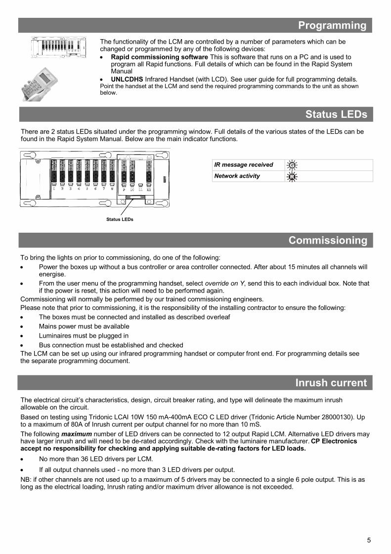
Programming
Status LEDs
Status LEDs
There are 2 status LEDs situated under the programming window. Full details of the various states of the LEDs can be found in the Rapid System Manual. Below are the main indicator functions.
The functionality of the LCM are controlled by a number of parameters which can be changed or programmed by any of the following devices:
• Rapid commissioning software This is software that runs on a PC and is used to program all Rapid functions. Full details of which can be found in the Rapid System Manual
• UNLCDHS Infrared Handset (with LCD). See user guide for full programming details. Point the handset at the LCM and send the required programming commands to the unit as shown below.
The electrical circuit’s characteristics, design, circuit breaker rating, and type will delineate the maximum inrush allowable on the circuit.
Based on testing using Tridonic LCAI 10W 150 mA-400mA ECO C LED driver (Tridonic Article Number 28000130). Up to a maximum of 80A of Inrush current per output channel for no more than 10 mS.
The following maximum number of LED drivers can be connected to 12 output Rapid LCM. Alternative LED drivers may have larger inrush and will need to be de-rated accordingly. Check with the luminaire manufacturer. CP Electronics accept no responsibility for checking and applying suitable de-rating factors for LED loads.
• No more than 36 LED drivers per LCM.
• If all output channels used - no more than 3 LED drivers per output.
NB: if other channels are not used up to a maximum of 5 drivers may be connected to a single 6 pole output. This is as long as the electrical loading, Inrush rating and/or maximum driver allowance is not exceeded.
Inrush current
Commissioning
To bring the lights on prior to commissioning, do one of the following:
• Power the boxes up without a bus controller or area controller connected. After about 15 minutes all channels will energise.
• From the user menu of the programming handset, select override on Y, send this to each individual box. Note that if the power is reset, this action will need to be performed again.
Commissioning will normally be performed by our trained commissioning engineers.
Please note that prior to commissioning, it is the responsibility of the installing contractor to ensure the following:
• The boxes must be connected and installed as described overleaf
• Mains power must be available
• Luminaires must be plugged in
• Bus connection must be established and checked
The LCM can be set up using our infrared programming handset or computer front end. For programming details see the separate programming document.

6
Dimensions See diagrams opposite Weight 0.97kg (EBR-LCM12-12DD) Supply Voltage 220-240VAC Frequency 50Hz Relay rating Switched live 10A
Switched permanent live 6A Volt free output (VFC) 6A EBR-LCM10-10AD and EBR-LCM10-10DD only
Terminal Capacity Mains - 4mm2 in wiring compartment Switched inputs and CAN - 2.5mm2 in wiring compartment
Load per LCM 10A Load per channel 6A fluorescent and incandescent lighting 3A compact fluorescent lighting 3A low energy lighting 3A low voltage lighting (switch primary of
transformer) 3A fans and ventilation equipment Switch SON lighting loads via a contactor
Power consumption EBR-LCM8-8DD On 5100mW, Off 2630mW EBR-LCM10-10DD On 6220mW, Off 2920mW EBR-LCM10-10DD On 6670mW, Off 3310mW
Dimming Maximum 3 drivers / ballasts per channel (current limit 50mA per channel). Maximum 250mA per LCM.
Cable lengths for dimming outputs: 100m using 0.5mm2 wire 150m using 1.00mm2 wire 300m using 1.5mm2 wire
SELV There are 3 isolated circuits supplied from an isolating safety transformer.
• SELV rated Logic power (relay drive, microcontroller, CAN bus) has a nominal and maximum voltage of 13V.
• SELV inputs have a nominal voltage of 12 V and a maximum of 19V.
• The non-SELV circuitry of the Dimming outputs is 16V nominal and 22.5V maximum
Temperature -10ºC to 35ºC Humidity 5 to 95% non-condensing Material (casing) Flame retardant PC/ABS
Classifications Insulation Class II Purpose Automatic control Construction Independently mounted
control for surface mounting Ball pressure test Insulating material
retaining current carrying parts tested at 125°C, all other insulating materials tested at 75°C.
Type of action Type 1.B action micro disconnection Overvoltage Category III Software class Class A Pollution Degree 2
Compliance EMC-2014/30/EU LVD-2014/35/EU
For further compliance information visit www.cpelectronics.co.uk/compliance
Technical data
Part numbers
396mm
200mm
14
6m
m
12
7m
m
Fixing points M6 (1/4”)
Height EBR-LCM8-8AD and EBR-LCM8-8DD only Allow 150mm for total height of unit (including connectors and cable). All other LCMs with plug-in modules Allow 170mm for total height of unit (including connectors and cable).
LCM EBR-LCM8-8DD Rapid 8 channel LCM DALI / DSI dimming EBR-LCM8-8AD Rapid 8 channel LCM 1-10V dimming EBR-LCM8-8DD-EG Rapid 8 channel LCM DALI / DSI dimming + energy measurement
EBR-LCM8-8AD-EG Rapid 8 channel LCM 1-10V dimming + energy measurement EBR-LCM10-10DD Rapid 10 channel LCM DALI / DSI dimming + 1 x VFC output EBR-LCM10-10AD Rapid10 channel LCM 1-10V dimming + 1 x VFC output
EBR-LCM10-10DD-EG Rapid 10 channel LCM DALI / DSI dimming + 1 x VFC output + energy measurement EBR-LCM10-10AD-EG Rapid10 channel LCM 1-10V dimming + 1 x VFC output + energy measurement EBR-LCM12-12DD Rapid 12 channel LCM DALI / DSI dimming
EBR-LCM12-12AD Rapid12 channel LCM 1-10V dimming EBR-LCM12-12DD-EG Rapid 12 channel LCM DALI / DSI dimming + energy measurement EBR-LCM12-12AD-EG Rapid12 channel LCM 1-10V dimming + energy measurement
Modules EBR-MOD2-2DD 2 channel DALI / DSI + 1 x VFC output plug-in module EBR-MOD4-4DD 4 channel DALI / DSI plug-in module
EBR-MOD2-2AD 2 channel 1-10V + 1 x VFC output plug-in module EBR-MOD4-4AD 4 channel 1-10V plug-in module Accessories UNLCDHS Universal LCD programming handset
EBR-BT Bus terminator EBR-BR Bus repeater
350mm
IMPORTANT NOTICE! This device should be installed by a qualified electrician in accordance with the latest edition of the IEE Wiring Regulations and any applicable Building Regulations.

7
This page intentionally left blank

8
Ref: #WD745 Issue 8


