
K-Lock SlabFORMWORKK-Lock SlabFORMWORK

Slab Formwork (K-Lock)
LedgersAll ledgers have identical forged blade ends,
with a minimum of projection to avoid damage.
Other ladger sizes available are
1.3m, 1.2m, 1.0m, 0.9m
SIZE WT.
(m) (kg)
3.0 14.8
2.8 14.0
2.5 12.4
2.3 11.4
2.0 10.0
1.8 9.0
1.5 7.9
1.3 6.5
1.0 5.0
0.8 4.1
StandardsMaximum led load capacity : 57kN
Slab Formwork (K-Lock)
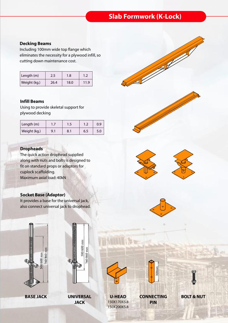
Decking BeamsIncluding 100mm wide top flange which
eliminates the necessity for a plywood infill, so
cutting down maintenance cost.
Length (m) 2.5 1.8 1.2
Weight (kg.) 26.4 18.0 11.9
Infill BeamsUsing to provide skeletal support for
plywood decking
DropheadsThe quick action drophead supplied
along with nuts and bolts is designed to
fit on standard props or adaptors for
cuplock scaffolding.
Maximum axial load: 40kN
Socket Base (Adaptor)It provides a base for the universal jack,
also connect universal jack to drophead.
Length (m) 1.7 1.5 1.2 0.9
Weight (kg.) 9.1 8.1 6.5 5.0
BASE JACK UNIVERSALJACK
U-HEAD150X170X5.8150X200X5.8
CONNECTINGPIN
BOLT & NUT

Slab Formwork (K-Lock)
1.3m
1.25m
1.2m1.2m
'L'
'L' 'L
'
CANTILEVERFRAMEAVAILABLE SIZES:L : 1.5M L : 1.0M
CANTILEVERBEAM FRAMEAVAILABLE SIZES:L : 1.5M L : 1.0M
INTERNAL BEAMBRACKETAVAILABLE SIZES:L : 1.5M L : 1.0M
1m (
0.5m
)

Slab Formwork (K-Lock)K-LOCK
TECHNICAL DETAILS PERMISSIBLE LOADS ON BASE COMPONENTSVertical axial load up to 57kN. The loadings will vary according to the horizontal loads taken into account and the actual extension of the jack required.
K-LOCK SUPPORT GUIDEFor standards at the begining and end of a row, the loading figures for the top and base lifts have to be reduced by 5%, except if jack bracing is used. This also applies to the use of K-Lock in towers and single bays.At least two lacing levels have to be used on each standard. When calculating horizontal forces, include wind forces, the effect of eccentricity, and out of plump (in accordance with British Standard 5975).Take care that the structure is stable in the unloaded condition, especially if towers or narrow structures are used.�All standards should be erected plumb.Horizontal forces should be distributed over all standards as evenly as possible.Sound footings should be provided to prevent settlement of the standards.

Assembly of decking on k-lock scaffolding
Space out socket bases and stand in jacks if required (plain shank at top).
Assemble a standard on a jack and two ledgers at right angles in a lower cup of this standard. Drop the upper cup of the joint over the two blade ends. Do not tighten.
Take a second standard and assemble on another jack, fixing the blade end of the previously assembled ledger into the cup of this standard. Repeat for the third standard to complete a right angled comer.
Add the fourth standard and two more ledgers in a similar manner to complete the assembly of 4 standards and 4 ledgers.
Add the upper layer of four ledgers and two braces and assemble the upper jacks and drophead assembles on the top of the completed supporting grid.
Finally, add the primary beams and infills in the completed support structures and as grids are completed, tighten all joints.
Dismantling follows the same procedure whether the
techniques of 'early striking' are followed or not.
The advantages of early striking is that the primary beams and
infills may be removed while the concrete soffit remains
supported and completely undisturbed during it's curing
period. The primary beams and infills may therefore be
re-used this time, thus gaining further concrete production
with only and additional set of supporting components.
Primary beams and infills may be removed by striking the
drophead wedge. While the primary head of the drophead
remains in contact with the concrete, the striking of the
wedge allows the beams to drop about 115mm only giving
sufficient clearance for the removal of the infills.
Whether the advantages of 'early striking' are taken or not,
complete safety in dismanting operations is ensured as
primary beams and infills cannot fall to the ground but after
striking, must be removed manually.
To assemble Decking on K-Lock Scaffolding remove the
drophead assembly from the jack at one end and connect it to
the beam. The completed beam with its drophead can now be
raised and dropped over the jack.
DISMANTLING PROCEDURE
Adjacent supporting grids may be added in a similar way and primary beams and infills added until the required area is completed.
UP POSITION DOWN POSITION
Erection Sequence (for 4 standards and 2 beams)
1 2 3
4 5 6
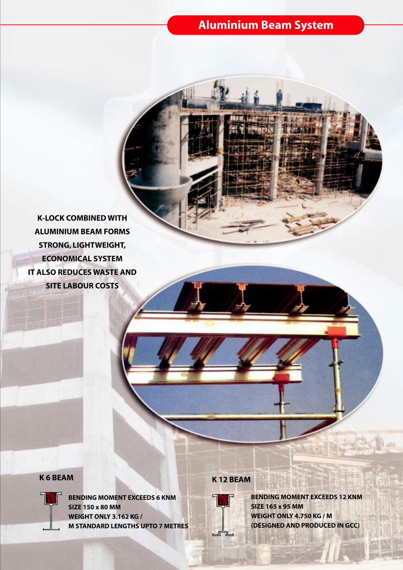
Aluminium Beam System
BENDING MOMENT EXCEEDS 6 KNM
SIZE 150 x 80 MM
WEIGHT ONLY 3.162 KG /
M STANDARD LENGTHS UPTO 7 METRES
K 6 BEAM
K-LOCK COMBINED WITH
ALUMINIUM BEAM FORMS
STRONG, LIGHTWEIGHT,
ECONOMICAL SYSTEM
IT ALSO REDUCES WASTE AND
SITE LABOUR COSTS
BENDING MOMENT EXCEEDS 12 KNM
SIZE 165 x 95 MM
WEIGHT ONLY 4.750 KG / M
(DESIGNED AND PRODUCED IN GCC)
K 12 BEAM

Head Office:New Industrial Area
P.O.Box: 2701, Ajman-U.A.ETel: +971-6-7439013, Fax: +971-6-7439017
E-mail: [email protected], Website: www.khk-scaffolding.com
Branches :A-Val Metal Resources, Inc.5925, Airport Road, Suite 200, Airway Centre,Mississauga L4V 1W1, Ontario, CanadaTel.: 001 905 405 6245, Fax: 001 905 672 8630email : [email protected] or [email protected]
Prime Metal CORPORATION - USA653 Route 52, Walden NY 12586United States of AmericaTel.: 001 - 845 - 778 4545Fax: 001 - 845 - 778 4218
Brisko Scaffolding Limited120 South lane New MaldenSurrey KT3 SEL EnglandTel.: 0044 - 20 - 83364595Fax: 0044 - 20 - 83364596
Winston Scaffolding Pty Ltd.44-46 Gould StreetSouth Strathfield, N.S.W. 2136Tel.: 00 - 02 - 97588700Fax: 00 - 02 - 97587263


