Download - Jeppesen Introduction

::JEPPESEN INTRODUCTION 30 DEC 05
TABLE OF CONTENTS
Below is a complete list of the standard contents of Airway Manual. Limited or special coverages may not contain all items, but that material which is included should be arranged in the order outlined.
CHART GLOSSARY . . . . . . . . . . . . . . . . . . . . . . . . . . . . . . . . . . . . . . . . . . . . . . . . • • . • . . . . . . . . . . . . . . . . . 1
ABBREVIATIONS . . . . . . . . . . . . . . . • • . . . . . . . . . . . . . . . . • . . • • . . . . . . . . . . . . . . • • • • • . . . . . . . . . . . . . 41
ENROUTE CHART LEGEND . . . . . . . . . . . . . . . . . . . . . . . . . . . . . . . . . . . . . . . . • • • . . . . . . . . . . . . . • . . . . 51 General . . . . . . . . . . . . . . . . . . . . . . . . . . . . . . . . . . . . . . . . . . . . . . . . . . . . • • . . . . . . . . . . . . . . . . . . . . . 5 1 Jeppesen IFR Enroute Plotter Instructions - Enroute and Area Charts . . . • • . . . . . . . . . . . . . . • . • • . . . 51 Navaid Symbols . . . . . . . . . . . . . . . . . . . . . . . . . . . . . . . . . . . . . . . . . . . . . • • . . . . . . . . . . . . . . . . • • . . . 52 Navaid Identification . . . . . . . . . . . . . . . . . . . . . . . . • • . • . . . . . . . . . . . . . • • • • . . . . . . . . . . . . . . . . • . . . 53 Communications . . . . . . . . . . . . . . . . . . . . . . . . . . • • • . . . . . . . . . . . . . . . • • • . . . . . . . . . . . . . . • • . . . . . 53 Navaid / Communication Data . . . . . . . . . . . . • • • • . • . . . . . . . . . . . . . • • • . • . . . . . . . . . . . . . • • • . . . . . 54 Restricted Airspace . . . . . . . . . . . . . . . . . . . . • • • • . . . . . . . . . . . . . . . . • • . . . . . . . . . . . . . . . • • . • . . . . . 54 Restricted Airspace Designation . . . . . . . . . • • . . . . . . . . . . . . . . . . • • • . . . . . . . . . . . . . . . • • • . . . . . . . . 55 Airports . . . . . . . . . . . . . . . . . . . . . . . . . . . . . • • . . . . . . . . . . . . . . . . • • . • . . . . . . . . . . . . . • . • . . . . . . . . 55 Airway and Route Components . . . . . . . . . . . . . . . . . . . . . . . . . • . . • • . . . . . . . . . . . . . . . • . . . . . . . . . . 55 Airway Information . . . . . . . . . . . . . . . . . . . . . . . . . . • • • . • . . . . . . . . . . . . • . • • • • • . . . . . . . . 56 Low & High/Low Altitude Enroute Chart Legend . . . . . . . . . . . . • • . . . . . . . . . . . . . . . . • . . . . . . . . . . . . 57 United States Low Altitude Enroute & Area Chart Legend . . . . . . . . . . . . . . . . . . . . . . . . . . . . . . . . . . . . 58 High Altitude Enroute Chart Legend . . . . . . . . . . . . . . . . . . . . . . . . . . . . . . . . . . . . . . . . . . . . . . . . . . . . . 59 Australia Enroute & Area Chart Legend . . . . . . . . . . . . . . . . . . . . . . . . . . . . . . . . . . . . . . . . . . . . . . . . . . 60 Airway Navaid/Reporting Point By·Pass. . . ... . . . .... . . . . ..... . . . . .. . .. . . . ..... . . . . . ... 61 ICAO Airspace Classifications . . . . ..... . . .... . . . . . .. . . . . . . . ... . . . . .. . . . 61 Orientation . . . ....... ... . . . . . ...... . . . . . ............ . . . . . . . . .... . ....... 62 Border Information . . . . . . • . . . . . . . . . . . . . . . . . • • • . . . . . . . . . . . . . . . . • • . . . . . . . . . . . . . . . . . . . . . 62 Miscellaneous . . . . . . . . . . . . . . . . . . . . . . . . . . . . . . . . . . . . . . . . . . . . . . . . . . . . . . . . . . . . . . . . . . . . . . 62 U.S. GPS MEAs . . . . . . . . . . . . . . . . . . . . . . . . . . . . . . . . . . . . . . . . . . . . . . . • . . . . . . . . . . . . . . . . . . . . 63 U.S. Series 800 and 900 Designated RNAV Routes . . . . . . . . . . . . . . . . . . . . . . • • • • • . . . . . . . . • . . . . 63 Australia and Canada T RNAV Routes. . . . . . . . . . . . . . . . . . . . . . • . • • . . . . . . . . . . . . . . . . • . . . 63
ENROUTE CHART LEGEND - HIGH ALTITUDE CHARTS . . . . . . . . . . . . . . . • • . . . . . . . . . . . . . . . • • . . . 71
ENROUTE CHART LEGEND - AREA CHARTS . . . . . . . . . . . . . . . . . . . . . . . . . . . . . . . . . . . . . . . . . • • . . . 71 Generalized Terrain Contours . . . . . . . . . . . . . . . . • • • . . . . . . . . . . . . . . . • • • . . . . . . . . . . . . . • • • • • . . . 72
CLASS B AIRSPACE CHART LEGEND . . . . . . • • . • . . . . . . . . . . . . . . • • • • • . . . . . . . . . . . . . . • • • • . . . . . . 75
SID/DP & STAR LEGEND . . . . . . . . . . . . . . . . . . . . . • • . . . . . . . . . . . . . . . . • • . • . . . . . . . . . . . . . . • • . . . . . 81 Graphic . . . . . . . . . . . . . . . . . . . . . . . . . . • • • . . . . . . . . . . . . . • . . • • . . . . . . . . . . . . . . . . • • • . . . . . 82 Route Portrayal . . . . . . . . . . . . . . . . . . . . . . • • . . . . . . . . . . . . . . . . • • • . . . . . . . . . . . . . . . . • • . • . . . . . . 82 Procedure Applicable to USA FAA only . . . . • . • • . . . . . . . . . . . . . • . . • • . . . . . . . . . . . . . • . • • . • . . . . . 84
APPROACH CHART LEGEND . . . . . . . . . . . . . . . • • • . . . . . . . . . . . . . . . . • • . . . . . . . . . . . . . . . . • . • . . . . 1 01 Formats . . . . . . . . . . . . . . . . . . . . . . . . . . . . . • . . . . . . . . . . . . . . . . • • . . . . . . . . . . . . . . . . . . • • • • . . . . 1 01 Heading . . . . . . . . . . . . . . . . . . . . . . • . . . . . . . . . . . . . . . . . • • . . . . . . • . . • . . . . . . 1 02 Approach Plan View . . . . . . . . . . . . . . . • • . . . . . . . . . . . . . . . . . . . • • • • • . . . . . . . . . . . . . . . • . . . . . . . 1 04 Profile View . . . . . . . . . . . . . . . . . . . . . . . • . . . . . . . . . . . . . . . . . . . • . • . . . . . . . . . . . . . . . • . • . . . . . . . 1 08 Landing Minimums . . . . . . . . . . . . . • • • . . . . . . . . . . . . . . . . . . • . . . . . . . . . . . . . . . . . . . . . . . . . . . . . . 1 1 2 Airport Chart Format . . . . . . . . . . . . . . . • • . • • • • • . . . . . . . . . . . . . . . • • • . . . . . . . . . . . . . . . . . . . . . . . 1 1 6 Airport Plan View . . . . . . . . . . . . . . . . . . . . .. . . . . . . . . . . . . . . . . . . . . . . . . . . . . . . . . . . . . . . . . . . . . 1 1 7 Additional Runway Information . . . . . . . . . . . . . . . . . . . . . . . . . . . . . . . . . . . . . . . . . . . . . . . . . . . . . . . . 118 Lighting Systems . . . . . . . . . . . . . . . • . • • • • • . . . . . . . . . . . . . . . . . . . . . . . . . . . . . . . . . • • • • . . . . . . . 121 Takeoff and Alternate Minimums . . . . . . . . . . . . . . . . . . • • . . . . . . . . . . . . . . . . • • . . . . . . . . . . . . . . . . 125
VOR DME RNAV APPROACH CHART LEGEND . . . . . . . . . . . . . . . . . . . . . . . . • . • . . . . . . . . . . . . . . . 131
CHARTED VISUAL FLIGHT PROCEDURES. . . . . .. . . . . . .. . . . . ... . ...... . . ... . . .......... 1 37 C VFPs (USA Only) . . . . . . . . . . . . . . . . . . . . . . . . . . . . . . . . . . . . . . . . . . . . . . . • . . • . . . . . . . . . . . . . . 137
APPROACH CHART LEGEND - GPS APPROACH CHARTS . . . . . . . . . . . . . . . . • . . . . . . . . . . . . . . . . . 147
(!I JEPPESEN SANOE;RSON, INC .• 1998. 2005. ALL RIGHTS RESERVED.
II 30 DEC 05 INTRODUCTION =�.JEPPESEN TABLE OF CONTENTS
APPROACH CHART LEGEND NEW FORMAT (BRIEFING STRIP CONCEPT) . . . . . . NEW FORMAT 1 General. . . . . . . . . . . . . . . . . . . . . . . . . . . . . . .. . . . . . . . . . . . . .. NEW FORMAT 1 Approach Chart Heading . . . . . . . . . . . . • . • . . . . . . . . . . . . . . . • • . . . . . . . . . . . . . . . . . . N EW FORMAT 2 Approach Plan View . . . . . . . .... . . . . . ... . . . . . . . ... . . . . . . ..... . . . . . ..... . . . . NEW FORMAT 3 Profile View. . . . . . . . .. . . . . . . . . . . . . .... . . . . . ... . . . . . . . . . .. . . . . .. NEW FORMAT 3 Conversion Tables, Lighting Box and Missed Approach Icons . . . . . ... . . . . ...... . . . . NEW FORMAT 4 Vertical Navigation (VNAV) . .. . . . .. ... . .. . . . . . . .. . . ...... .. . . . . . ... . . . N EW FORMAT 5 Airport Chart Format. . . . . . . . . . . . . . . . . . . . . . . . . . . • . • • • . . . . . . . . . ..... . . . . .NEW FORMAT 6
SID/DP & STAR CHART LEGEND NEW FORMAT . . . . . . . . . . . . . . • • . . . . . . . . . . . . . . . N EW FORMAT 7
UNITED STATES AIRPORT SIGN SYSTEMS . . . . . . . . . . . . . . . . . . . . . . . . . . . . . . . . . . . . . . . . . . . . . . . 1 51 Mandatory Signs. . . . . . . . . . . . . . . . . . . . . . . . • • • • . . . . . . . . . . . . . . . . • • . • • . . . . . . . . . . . 1 51 Location Signs . . . . . . . . . . . . . . . . . . . . . . . . . . . . . . . . . . . . • . . . . . . . . . . . . . . . . . . . . . . . . . . . . . . . 1 51 Direction Signs . . . . . . . . . . . . . . . . . . . . . . . . . . . . . . . . . . . . . . . . . . . . . . . . . • . . . . . . . . 1 52 Destination Signs . . . . . . . . . . . . . . . . . . . . . . . . . . . . . . . . . . . . . . . . . . . . . . . . . . . . • • • . • . . . . . . . . . 1 52 Information Signs . . . . . . . . . . . . . . . . . . . . . . . . . . . . . . . . . . . . . . . . . • • • . . . . . . . . . . . 1 52 Runway Distance Remaining Signs . . . . . . . . . . . . . . . . . . . . . . . . • . . . . . . . . . . . . . . . . • • . . . . . . . . . 1 52 Examples . . . . . . . . . . . . . . . . . . . . . . . . . . . . . . . . . . • . • • . . . . . . . . . . . . . . . . . • • . . . . . . . . . 153
UNITED STATES INSTRUMENT RUNWAY MARKINGS Enhanced Taxiway Centerline and Runway Holding Position Markings . .
. . . . . . . . . . . . . . . . • • • . . . 1 56 . . . . . . . . • . . • . . . . . . . 158
ICAO RECOMMENDED AIRPORT SIGNS, RUNWAY AND TAXIWAY MARKINGS . . . . . . . . . . . . . • • . . . 1 61 Mandatory Instruction Signs. . . . . . . . . . . . . . . . . . . . ..... ... . . ..... . . . . . . ... . .. . . ........ 1 61 Information Signs . . . . . . . . . . . . . . . . . . . . . . . . . . . . • . . . . . . . . . . . . . . . . . . . . . . . . . . . . . 1 62 Mandatory I nstruction Markings. . . . . . . . . . . . . . • • • . . . . . . . . . . . . . . . . . • • . . . . . . . . . 163 Runway & I ntermediate Holding Position Markings . . . . . . . . . . . . . . . . . . . . . . . • • . . . . . . . . . . 1 64 Stop Bars/Runway Guard Lights/Runway Markings. . . . . . . . . . . . . . . . . . . . . . . . . . • • . • . . . . . . . 1 65 Threshold/Runway Designation/Runway Centerline Markings/High Speed Taxiway Turn·off I ndicator Lights (HSTIL) . . . . . . . . . . . . . . . . . . . . . . . . . . . . . . . . . . • • • . • . . . . . . 1 66 Runway Touchdown Zone/Runway Aiming Point Markings . . . . . . • . . .. . . . . . . . .. . . . . . . ... .. . 1 67 Runway Side Stripe Markings. . . . . . . . . . . . . . . . . . . . . . ... . . . . ........ . . . . . . ..... . 1 69 Displaced Threshold Markings . . . . . . . . . . . . . . . . . . . . . . . . . . . . . . . . . . . . . . . . . . . . 1 69 Closed Runways, Taxiways or Parts Thereof. . . . . . . . . . . . . . . . . . . • • . . . . . . . . . . . . . . . . . . • . . . 1 69 Non Load·Bearing Surtaces. . . . . . . . . • . . . . . . . . . . . . . . . • • • • • . . • . . . . . . 169 Pre·Threshold Area Marking (Chevron Marking) . . . . . . . . . . . . . . . . . . . . . • . . . . . . . . . 170
APPROACH CHART LEGEND - JAR·OPS 1 AERODROME MIN IMUMS . . . . . . . . . . . • • • • • . . . . . . . . . 171 General . . . . . . . . . . . . . . . . . . . . . . . . . . . . . . . . . . . . . . . . . . . . . . . . . . . . . . . . . . . . • • . • . . . . . . . 171 Take-off Minimums. . . . . . . . . . . . . . . . . . . . . . . . . . . . . • • . • . . . . . . . . . . . . . . . • • • • . • . . . . . 1 71 Format for Charts in JAA Member States . . . . . . . . . . . . . . . . . . . . . . . . . . . . . . . . . . . . . . . . . . . . . . . . 1 71 Straight-in Landing . . . . . . . . . . . . . . . . . . . . . . . . . . • . . . . . . . . . . . . . . . . . • . . . . . . . . . . . . 1 71 Circling Minimums . . . . . . . . . • . • • . . . . . . . . . . . . . . . . . . . . . . . . . . . . . . . • . . • • • . . . . . . 1 71 CAT II Minimums . .. . . . . . . . . . . . . . . . . . . . . . . . . . _ • . • • • . . . . . . . . . . . . . _ . . . . • . . . . . . . . . . . . . 1 72 JAA Aerodrome Minimums Listing . .... . . . . ..... . . . . . . . . . . . . . . . . . . . . . . • • • . . . . . . . . . . 1 72
NAV2001 , AERONAUTICAL INFORMATION NAVDATA DATABASE AND CHARTS . . . . • . . . . . . . . . . . . . 201 Preface. . . . . . . . . . . . . . . . . . . . . . . . . . . . . . . . . . . . . . . . . . • • • • . . . . . . . . . . 201 Effective Dates . . . . . . . . . . . . . . . . • • • • . . . . . . . . . . . . . . • • • • • . . . . . . . . . . . . . . . • • • • • . . . . . . . . . 202 Navaids . . . . . . . . . . . . . . . . . . . . . . • . • • . . . . . . . . . . . . . • . . . . . . . . . . . . . . . . . . . . . . • . . . . . . . . . . . 203 Waypoints. . . . . . . . . . . . . . . . . . . . . . . . . . . . . . . . . . . . . . .... . . 204 Airways . . . . . . . . . . . . . . . . . . . . . . . . . . . . . . . . . . . . . . . . . . . . . . . . . . . . . . • • . . . . . . . . . 206 Arrivals and Departures . . . . . . . . . . . . . . . . . . . . . . . . . . . . . . . . . . . . . • . • • • . . . . . . . . . . . . . . . . . . . 207 Approach Procedure (Titles and Omitted Procedures). . . . . . . . . . . . . . • • • . . . . . . . . . . . . . . . . 209 Approach Procedures (Plan View) . . . . . . . . . . . . . . . . . . . . • . . . . . . . . . . . . . . • • . • . . . . . . . . . . . . . . 21 0 Approach Procedures (Profile) . . . . . . . . . . . . . . . . . . . . • • . . . . . . . . . . . . . . . • • • . . . ........ 212 Approach Procedures . . . . . . . . . . . • . . . . . . . . . . • . • • . . . . . . . . . . . . . . . . • • • . . . . . . . . . . . . . . . . 215 Glossary/Abbreviations. . . . . . . . . . . . . . . . . . . . . . • • . . . . . . . . . . . . . . . . • • • . • . . . . . . . . . . . . . . 217
@JEPPESENSANDERSON,INC . . 1991l, 2005. ALL RIGHTS RESERVEO.
w w '" .. -'
==JEPPESEN 27 JUL 07 INTRODUCTION
CHART GLOSSARY
I This glossary provides definitions that are unique and abbreviations commonly used in Jeppesen publications. No attempt has been made to list all the terms of basic aeronautical nomenclature.
Because of the international nature of flying, terms used by the FAA (USA) are Included when they differ from International Civil Aviation Organization (ICAO) definitions. An arrow or vertical bar, that is omitted on all new pages, tables of contents, tabular listings and graphics, Indicates changes.
DEFINITIONS
ACCELERATE STOP DISTANCE AVAILABLE (ASDA) - The length of the takeoff run available plus the length of the stopway, if provided. ADEQUATE VIS REF (Adequate Visual Reference) - Runway markings or runway lighting that provides the pilot with adequate visual reference to continuously identify the takeoff surface and maintain directional control throughout the takeoff run. ADVISORY ROUTE (ADR) - A designated route along which air traffic advisory service is available. NOTE: Air traffic control service provides a much more complete service than air traffic advisory service; advisory areas and routes are therefore not established within controlled airspace, but air traffic advisory service may be provided below and above control areas.
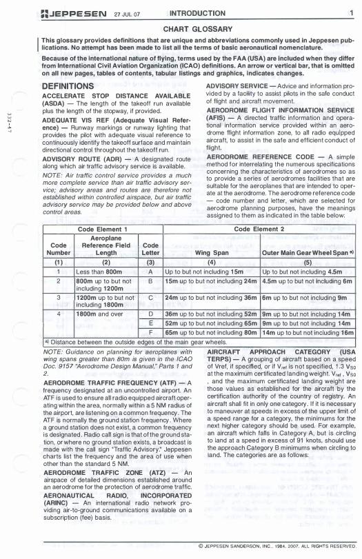
Code Element 1 Aeroplane
Code Reference Field Code Number Length Letter
(1 ) (2) (3)
ADVISORY SERVICE - Advice and information provided by a facility to assist pilots in the safe conduct of flight and aircraft movement. AERODROME FLIGHT INFORMATION SERVICE (AFIS) - A directed traffic information and operational information service provided within an aerodrome flight information zone, to all radio equipped aircraft, to assist in the safe and efficient conduct of flight. AERODROME REFERENCE CODE - A simple method for interrelating the numerous specifications concerning the characteristics of aerodromes so as to provide a series of aerodromes facilities that are suitable for the aeroplanes that are intended to operate at the aerodrome. The aerodrome reference code - code number and letter, which are selected for aerodrome planning purposes, have the meanings assigned to them as indicated in the table below:
Code Element 2
Wing Span Outer Main Gear Wheel Span a) (4) (5)
1 Less than 800m A Up to but not including 1 5m Up to but not including 4.5m 2 800m up to but not B 15m up to but not including 24m 4.5m up to but not including 6m
including 1 200m 3 1200m up to but not C 24m up to but not including 36m 6m up to but not including 9m
including 1 800m 4 1800m and over D 36m up to but not including 52m 9m up to but not including 1 4m
E 52m up to but not including 65m 9m up to but not including 1 4m F 65m up to but not including 80m 1 4m up to but not including 16m
a) Distance between the outside edges of the main gear wheels. NOTE. GUidance on plannmg for aeroplanes wIth wing spans greater than 80m is given in the ICAO Doc. 9157 "Aerodrome Design Manual," Parts 1 and 2. AERODROME TRAFFIC FREQUENCY (ATF) - A frequency designated at an uncontrolled airport. An ATF is used to ensure all radio equipped aircraft operating within the area, normally within a 5 NM radius of the airport, are listening on a common frequency. The ATF is normally the ground station frequency. Where a ground station does not exist, a common frequency is designated. Radio call sign is that of the ground station, or where no ground station exists, a broadcast is made with the call sign ''Traffic Advisory." Jeppesen charts list the frequency and the area of use when other than the standard 5 NM.
AERODROME TRAFFIC ZONE (ATZ) - An airspace of detailed dimensions established around an aerodrome for the protection of aerodrome traffic. AERONAUTICAL RADIO, INCORPORATED (ARINC) - An international radio network providing air-to-ground communications available on a subscription (fee) basis.
AIRCRAFT APPROACH CATEGORY (USA TERPS) - A grouping of aircraft based on a speed of Vref, if specified, or if Vr.f is not specified, 1.3 Vso at the maximum certificated landing weight. Vr.f , Vso , and the maximum certificated landing weight are those values as established for the aircraft by the certification authority of the country of registry. An aircraft shall fit in only one category. If it is necessary to maneuver at speeds in excess of the upper limit of a speed range for a category, the minimums for the next higher category should be used. For example, an aircraft which falls in Category A, but is Circling to land at a speed in excess of 91 knots, should use the approach Category B minimums when circling to land. The categories are as follows:
© JEPPESEN SANDERSON. INC .. 1984. 2007. ALL RIGHTS RESERVED.
I I
2 INTRODUCTION 27 JUL 07
CHART GLOSSARY
Category A Category B
Category C
Category D
Category E
Speed less than 91 knots. Speed 91 knots or more but less than 1 21 knots. Speed 1 21 knots or more but less than 1 41 knots. Speed 1 41 knots or more but less than 1 66 knots. Speed 1 66 knots or more.
NOTE: Category E includes only certain Military Aircraft and is not included on Jeppesen Approach Charts.
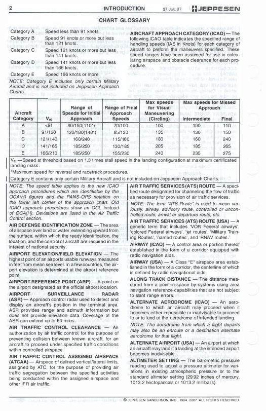
AIRCRAFT APPROACH CATEGORY (ICAO) - The following ICAO table indicates the specified range of handling speeds (lAS in Knots) for each category of aircraft to perform the maneuvers specified. These speed ranges have been assumed for use in calculating airspace and obstacle clearance for each procedure.
Max speeds Max speeds for Missed Range of Range of Final for Visual Approach
Aircraft Speeds for Initial Approach Maneuvering Category Vat Approach Speeds (Circling) Intermediate Final
A <91 90/1 50( 1 1 0*) 70/1 00 1 00 1 00 1 1 0 B 91/1 20 120/1 80(1 40*) 85/1 30 1 35 1 30 1 50 C 1 21/1 40 1 60/240 1 1 5/160 1 80 1 60 240 D 141/1 65 1 85/250 1 30/1 85 205 1 85 265 E 166/2 1 0 1 85/250 1 55/230 240 230 275
Vat -Speed at threshold based on 1 .3 times stall speed in the landing configuration at maximum certificated landing mass. *Maximum speed for reversal and racetrack procedures. Category E contains only certain Military Ai rcraft and is not included on Jeppesen Approach Charts.
NOTE: The speed table applies to the new IGAO approach procedures which are identifiable by the OGA(H) figures and the PANS-OPS notation on the lower left corner of the approach chart. Old ICAO approach procedures show an OGL instead of OGA(H). Deviations are listed in the Air Traffic Gontrol section.
AIR DEFENSE IDENTIFICATION ZONE - The area of airspace over land or water, extending upward from the surface, within which the ready identification, the location, and the control of aircraft are required in the interest of national security. AIRPORT ELEVATIONIFIELD ELEVATION - The highest point of an airports usable runways measured in feet from mean sea level . In a few countries, the airport elevation is determined at the airport reference point. AIRPORT REFERENCE POINT (ARP) - A point on the airport designated as the official airport location. AIRPORT SURVEILLANCE RADAR (ASR) - Approach control radar used to detect and display an aircraft's position in the terminal area. ASR provides range and azimuth information but does not provide elevation data. Coverage of the ASR can extend up to 60 miles. AIR TRAFFIC CONTROL CLEARANCE - An authorization by air traffic control, for the purpose of preventing collision between known aircraft, for an aircraft to proceed under specified traffic conditions within controlled airspace. AIR TRAFFIC CONTROL ASSIGNED AIRSPACE (ATCAA) - Airspace of defined verticaillateral limits, assigned by ATC, for the purpose of providing air traffic segregation between the specified activities being conducted within the assigned airspace and other IFR air traffic.
I AIR TRAFFIC SERVICES (ATS) ROUTE - A speci-fied route designated for channeling the flow of traffic as necessary for provision of air traffic services. NOTE: The term "ATS Route" is used to mean var-iously, airway, advisory route, controlled or uncon-trolled route, arrival or departure route, etc.
-AIR TRAFFIC SERVICES (ATS) ROUTE (USA) A generic term that includes 'VOR Federal airways' , 'colored Federal airways', 'jet routes', 'Military Training Routes', 'named routes', and 'RNAV routes.' AIRWAY (ICAO) - A control area or portion thereof established in the form of a corridor equipped with radio navigation aids. AIRWAY (USA) - A Class "E" airspace area established in the form of a corridor, the centerline of which is defined by radio navigational aids. ALONG TRACK DISTANCE - The distance measured from a point-in-space by systems using area navigation reference capabilities that are not subject to slant range errors. ALTERNATE AERODROME (ICAO) - An aerodrome to which an aircraft may proceed when it becomes either impossible or inadvisable to proceed to or to land at the aerodrome of intended landing. NOTE: The aerodrome from which a flight departs may also be an enroute or a destination alternate aerodrome for that flight.
ALTERNATE AIRPORT (USA) - An airport at which an ai rcraft may land if a landing at the intended airport becomes inadvisable. ALTIMETER SETTING - The barometric pressure reading used to adjust a pressure altimeter for variations in existing atmospheric pressure or to the standard altimeter setting (29.92 inches of mercury, 1 01 3.2 hectopascals or 1 01 3.2 millibars).
© JEPPESEN SANDERSON, INC., 1984, 2007. ALL RIGHTS RESERVED.
==.JEPPESEN 27 JUL 07 INTRODUCTION 3
CHART GLOSSARY
ALTITUDE (ICAO) - The vertical distance of a level, a point, or an object considered as a point, measured from Mean Sea Level (MSL). ALTITUDE (USA) - The height of a level, point or object measured in feet Above Ground Level (AGL) or from Mean Sea Level (MSL).
a. AGL Altitude - Altitude expressed in feet measured above ground level (QFE).
b. MSL Altitude - Altitude expressed in feet measured from mean sea level (QNH) .
c. Indicated Altitude - The Altitude as shown by an altimeter. On a pressure barometric altimeter it is altitude as shown uncorrected for instrument error and uncompensated for variation from standard atmospheric conditions.
APPROACH PROCEDURE WITH VERTICAL GUIDANCE (APV) - An instrument approach based on a navigation system that is not required to meet the precision approach standards of ICAO Annex 10 but provides course and glide path deviation information (sometimes referred to as "semi-precision"). BaroVNAV, LDA with glide path, LNAVNNAV and LPV are examples of APV approaches. AREA NAVIGATION/RNAV - A method of navigation that permits aircraft operations on any desired course within the coverage of station referenced navigation signals or within the limits of self contained system capability. ARRIVAL ROUTES (ICAO) - Routes on an instrument approach procedure by which aircraft may proceed from the enroute phase of flight to the initial approach fix. ATIS - ASOS INTERFACE - A switch that allows ASOS weather observations to be appended to the ATIS broadcast, making weather information available on the same (ATIS) frequency H24. When the tower is open, ATIS information and the hourly weather will be broadcast. When the tower is closed, one-minute weather information updates are broadcast, and the controller can add overnight ATIS information to the ASOS automated voice weather message.
I ATS ROUTE - See "AIR TRAFFIC SERVICES (ATS) ROUTE" AUTOMATIC DEPENDENT SURVEILLANCE (ADS) - A surveillance technique, in which aircraft automatically provide, via a data link, data derived from on-board navigation and position fixing systems, including aircraft identification, four-dimensional position and additional data as appropriate. AUTOMATED SURFACE OBSERVATION SYSTEM (AS OS) - The Automated Surface Observation System, in the United States, is a surface weather observing system implemented by the National Weather Service, the Federal Aviation Administration and the Department of Defense. It is designed to support aviation operations and weather forecast activities. The ASOS provides continuous minute-by-minute observations and performs the basic observing functions necessary to generate an aviation routine weather report (METAR) and other
aviation weather information. ASOS information may be transmitted over a discrete VHF radio frequency or the voice portion of a local navaid. AUTOMATED WEATHER OBSERVING SYSTEM (AWOS) - An automated weather reporting system which transmits local real-time weather data directly to the pilot.
AWOS-A Only reports altimeter setting. AWOS-1 Usually reports altimeter setting, wind
data, temperature, dewpoint and density altitude.
AWOS-2 Reports same as AWOS-1 plus visibil ity. AWOS-3 Reports the same as AWOS-2 plus
cloud/ceiling data. AUTOMATED WEATHER SENSOR SYSTEM (AWSS) - A surface weather observing system similar to AWOS and ASOS, providing all the weather information furnished by ASOS systems. The AWSS sensor suite automatically collects, measures, processes, and broadcasts surface weather data including altimeter setting, temperature and dew point, cloud height and coverage, visibility, present weather (rain, drizzle, snow), rain accumulation, freezing rain, thunderstorms, fog, mist, haze, freezing fog, as well as wind speed, direction, and gusts. BRAKING ACTION (GOOD, FAIR, POOR, NIL) - A report of conditions on the airport movement area providing a pilot with a degree/quality of braking that might be expected. Braking action is reported in terms of good, fair, poor, or nil. CARDINAL ALTITUDES OR FLIGHT LEVELS - "Odd" or "Even" thousand-foot altitudes or flight levels; e.g., 5000, 6000, 7000, FL60, FL250, FL260, FL270. CATCH POINT - A fixlwaypoint that serves as a transition point from the high altitude waypoint navigation structure to the low altitude structure or an arrival procedure (STAR). CEILING (ICAO) - The height above the ground or water of the base of the lowest layer of cloud below 6000 meters (20,000 feet) covering more than halfthe sky. CEILING (USA) - The height above the earth's surface of the lowest layer of clouds or obscuring phenomena that is reported as "broken", "overcast", or "obscuration", and not classified as 'thin", or "partial". CHART CHANGE NOTICES - Jeppesen Chart Change Notices include significant information changes affecting Enroute, Area, and Terminal charts. Entries are published until the temporary condition no longer exists, or until the permanent change appears on revised charts. Enroute chart numbers / panel numbers / letters and area chart identifiers are included for each entry in the en route portion of the Chart Change Notices. To avoid duplication of information in combined Enroute and Terminal Chart Change Notices , navaid conditions, except for ILS components, are listed only in the Enroute portion of the Chart Change Notices . All times are local unless otherwise indicated. Arrows
© JEPPESEN SANDERSON, INC., 1984, 2007. ALL RIGHTS RESERVED.

4 INTRODUCTION 27 JUL 07 =:JEPPESEN CHART GLOSSARY
I indicate new or revised information. Chart Change Notices are only an abbreviated service. Always ask for pertinent NOTAMs prior to flight. COMMON TRAFFIC ADVISORY FREQUENCY (CTAF) (USA) - A frequency designed for the purpose of carrying out airport advisory practices while operating to or from an uncontrolled airport. The CTAF may be a UNICOM, Multicom, FSS, or tower frequency. COMMUNITY AERODROME RADIO STATION (CARS) - An aerodrome radio that provides weather, field conditions, accepts flight plans and position reports. COMPULSORY REPORTING POINTS - Reporting points which must be reported to ATC. They are designated on aeronautical charts by solid triangles or filed in a flight plan as fixes selected to define direct routes. These points are geographical locations which are defined by navigation aids/fixes. Pilots should discontinue position reporting over compulsory reporting points when informed by ATC that their aircraft is in "radar contact." CONDITIONAL ROUTES (CDR) (Europe) -
Category 1 ,2,3.
Category 1: Permanently plannable CDR during designated times.
Category 2: Plannable only during times designated in the Conditional Route Availability Message (CRAM) published at 1 500Z for the 24 hour period starting at 0600Z the next day.
Category 3: Not plannable. Usable only when directed by ATC.
CONTROL AREA (ICAO) - A controlled airspace extending upwards from a specified limit above the earth. CONTROLLED AIRSPACE - An airspace of defined dimensions within which air traffic control service is provided to IFR flights and to VFR fl ights in accordance with the airspace classification. NOTE: Controlled airspace is a generic term which covers ATS airspace Classes '�", "8", "C", "0", and "E".
CONTROL ZONE (ICAO) - A controlled airspace extending upwards from the surface of the earth to a specified upper limit. COURSE -
a. The intended direction of flight in the horizontal plane measured in degrees from north.
b . The ILS localizer signal pattern usually specified as front course or back course.
c. The intended track along a straight, curved, or segmented MLS path.
CRITICAL HEIGHT - lowest height in relation to an aerodrome specified level below which an approach procedure cannot be continued in a safe manner solely by the aid of instruments.
DECISION ALTITUDE/HEIGHT (DA/H) (ICAO) - A specified altitude or height (A/H) in the precision approach at which a missed approach must be initiated if the required visual reference to continue the approach has not been established. NOTE:
a. Decision altitude (DA) is referenced to mean sea level (MSL) and decision height (DH) is referenced to the threshold eI9l'ation.
b. The required visual reference means that section of the visual aids or of the approach area which should have been in view for sufficient time for the pilot to have made an assessment of the aircraft position and rate of change of position, in relation to the desired flight path.
DECISION HEIGHT (DH) (USA) - With respect to the operation of aircraft, means the height at which a decision must be made, during an IlS or PAR instrument approach, to either continue the approach or to execute a missed approach. NOTE: Jeppesen approach charts use the abbreviation DA(H). The decision altitude "DA" is referenced to mean sea level (MSL) and the parenthetical decision height (DH) is referenced to the TDZE or threshold elevation. A DA(H) of 1440 ft (200 ft is a Decision Altitude of 1440 ft and a Decision Height of 200 ft.
DEPARTURE CLEARANCE VIA DATA LINK (DCL) - Provides assistance for requesting and delivering information and clearance, with the objective of reducing aircrew and controller workload. The DCl service shall be initiated by the aircrew at a suitable time between Ti and Tt where:
Ti - the earliest time at which a DCl service can be initiated;
Tt - the latest time after which an aircrew, having not completed the DCl service, is still able to receive by voice procedures and in due time, the vocal departure clearance.
The third time parameter of the DCl acknowledge procedure is T1 where:
T1 - timer implemented in the ATS ground system between the sending by ATS ground system of the DCl clearance message and the reception by it of the read-back of DCl clearance message.
I DIRECT ROUTE ---l!l - A requested route pub-lished on a Jeppesen Enroute or Area chart to assist pilots who have previous knowledge of acceptance of these routes by ATC. Use of a Direct route may require prior ATC approval and may not provide ATC or Advisory services, or be acceptable in flight plans. DISPLACED THRESHOLD - A threshold that is located at a point on the runway other than the designated beginning of the runway. ENROUTE FLIGHT ADVISORY SERVICE (FLIGHT WATCH) - A service specifically designed to provide, upon pilot request, timely weather information pertinent to the type of flight, intended route of flight, and altitude. The FSSs providing this service are indicated on Jeppesen Enroute and Area charts.
© JEPPESEN SANDERSON, INC., '984, 2007. ALL RIGHTS RESERVED.
w W tv ,
en >-'
==.JEPPESEN 27 JUL 07 INTRODUCTION 5
CHART GLOSSARY
FAA AIR CARRIER OPERATIONS SPECIFICATIONS - Document issued to users operating under Federal Aviation Administration Regulations (FAR) Parts 1 21,1 25,1 27,1 29, and 1 35. Operations Specifications are established and formalized by FARs. The primary purpose of FAA Air Carrier Operations Specifications is to provide a legally enforceable means of prescribing an authorization, l imitation and/or procedures for a specific operator. Operations Specifications are subject to expeditious changes. These changes are usually too time critical to adopt through the regulatory process. FEEDER FIX - The fix depicted on instrument approach procedure charts which establishes the starting point of the feeder route. FEEDER ROUTE - Routes depicted on instrument approach procedure charts to designate routes for aircraft to proceed from the en route structure to the initial approach fix (lAF). FINAL APPROACH COURSE - A published MLS course, a straight line extension of a localizer, a final approach radial/bearing, or a runway centerline all without regard to distance. FINAL APPROACH (ICAO) - That part of an instrument approach procedure which commences at the specified final approach fix or point, or where such a fix or point is not specified,
a. at the end of the last procedure turn, base turn or inbound turn of a racetrack procedure, if specified; or
b. at the point of interception of the last track specified in the approach procedure; and ends at a point in the vicinity of an aerodrome from which:
1 . a landing can be made; or 2. a missed approach procedure is initiated.
FINAL APPROACH FIX (FAF) - The fix from which the final approach ( lFR) to an airport is executed and which identifies the beginning of the final approach segment. It is designated in the profile view of Jeppesen Terminal charts by the Maltese Cross symbol for non-precision approaches and by the glide slope/path intercept point on precision approaches. The glide slope/path symbol starts at the FAF. When ATC directs a lower-than-published Glide Slope/Path Intercept Altitude, it is the resultant actual point of the glide slope/path intercept. FINAL APPROACH FIX (FAF) (AUSTRALIA) - A specified point on a non-precision approach which identifies the commencement of the final segment. The FAF is designated in the profile view of Jeppesen Terminal charts by the Maltese Cross symbol. FINAL APPROACH - IFR (USA) - The flight path of an aircraft which is inbound to an airport on a final instrument approach course, beginning at the final approach fix or point and extending to the airport or the point where a circle-to-Iand maneuver or a missed approach is executed. FINAL APPROACH POINT (FAP) (USA) - The point, applicable only to a non-precision approach with no depicted FAF (such as an on-airport VORl, where the aircraft is established inbound on the final approach course from the procedure turn and where
the final approach descent may be commenced. The FAP serves as the FAF and identifies the beginning of the final approach segment. FINAL APPROACH FIX OR POINT (FAP) (ICAO) - That fix or pOint of an instrument approach procedure where the final approach segment commences. FINAL APPROACH POINT (FAP) (AUSTRALIA) - A specified point on the glide path of a precision instrument approach which identifies the commencement of the final segment. NOTE: The FAP is co-incident with the FAF of a localizer-based non-precision approach.
FLIGHT INFORMATION REGION (FIR, UIR) - An airspace of defined dimensions within which Flight Information Service and Alerting Service are provided.
a. Flight Information Service (FIS) - A service provided for the purpose of giving advice and information useful for the safe and efficient conduct of flig hts.
b. Alerting Service - A service provided to notify appropriate organizations regarding aircraft in need of search and rescue aid, and assist such organizations as required.
FLIGHT WATCH (USA) - A shortened term for use in air-ground contacts to identify the flight service station providing Enroute Flight Advisory Service; e.g., "Oakland Flight Watch." FLY-BY WAYPOINT - A fly-by waypoint requires the use of turn anticipation to avoid overshoot of the next flight segment. FLY-OVER WAYPOINT - A fly-over waypoint precludes any turn until the waypoint is overflown and is followed by an intercept maneuver of the next flight segment. GLIDE PATH (ICAO) - A descent profile determined for vertical guidance during a final approach. GLIDE SLOPE (GS) (USA) - Provides vertical guidance for aircraft during approach and landing. The glide slope/glidepath is based on the following:
a. Electronic components emitting signals which provide vertical guidance by reference to airborne instruments during instrument approaches such as ILS/MLS; or
b. Visual ground aids, such as VASI , which provide vertical guidance for a VFR approach or for the visual portion of an instrument approach and landing.
c. PAR, used by ATC to inform an aircraft making a PAR approach of its vertical position (elevation) relative to the descent profile.
GLIDE SLOPE I GLIDE PATH INTERCEPT ALTITUDE - The minimum altitude to intercept the glide slope/path on a precision approach. The intersection of the published intercept altitude with the glide slope/path, designated on Jeppesen Terminal charts by the start of the glide slope/path symbol, is the precision FAF; however, when ATC directs a lower altitude, the resultant lower intercept position is then the FAF.
© JEPPESEN SANDERSON, INC., 1984, 2007. ALL RIGHTS RESERVED.

6 INTRODUCTION 27 JUL 07 ::JEPPESEN CHART GLOSSARY
GLOBAL NAVIGATION SATELLITE SYSTEMS (GNSS) - An "umbrella" term adopted by the International Civil Aviation Organization (ICAO) to encompass any independent satellite navigation system used by a pilot to perform onboard position determinations from the satellite data. GLOBAL POSITIONING SYSTEM (GPS) - A space-based radio positioning, navigation, and time-transfer system. The system provides highly
accurate position and velocity information, and precise time, on a continuous global basis, to an unlimited number of properly equipped users. The system is unaffected by weather, and provides a worldwide common grid reference system, The GPS concept is predicated upon accurate and continuous knowledge of the spatial position of each satellite in the system with respect to time and distance from a transmitting satellite to the user. The GPS receiver automatically selects appropriate signals from the satellites in view and translates these into a three-dimensional position, velocity, and time. System accuracy for civil users is normally 1 00 meters horizontally. GRID MINIMUM OFFROUTE ALTITUDE (Grid MORA) - An altitude derived by Jeppesen or provided by State Authorities. The Grid MORA altitude provides terrain and man-made structure clearance within the section outlined by latitude and longitude lines. MORA does not provide for navaid signal coverage or communication coverage.
a, Grid MORA values derived by Jeppesen clear all terrain and man-made structures by 1 000 feet in areas where the highest elevations are 5000 feet MSL or lower. MORA values clear all terrain and man-made structures by 2000 feet in areas where the highest elevations are 5001 feet MSL or higher. When a Grid MORA is shown as "Unsurveyed" it is due to incomplete or insufficient information. Grid MORA values followed by a +/- denote doubtful accuracy, but are believed to provide sufficient reference point clearance.
b. Grid MORA (State) altitude supplied by the State Authority provides 2000 feet clearance in mountainous areas and 1000 feet in non-mountainous areas.
GROUND COMMUNICATIONS OUTLET (GCO) (USA) - An unstaffed, remotely controlled ground / ground communications facility. Pilots at uncontrolled airports may contact ATC and FSS via VHF to a telephone connection to obtain an instrument clearance or close a VFR or IFR flight plan. They may also get an updated weather briefing prior to takeoff. Pilots will use four "key clicks" on the VHF radio to contact the appropriate ATC facility, or six "key clicks" to contact FSS. The GCO system is intended to be used only on the ground. HEIGHT ABOVE AIRPORT (HAA) - The height of the Minimum Descent Altitude (MDA) above the published airport elevation. This is published in conjunction with circling minimums. HEIGHT ABOVE TOUCHDOWN (HAT) -The height of the Decision Height or Minimum Descent Altitude above the highest runway elevation in the touchdown
zone of the runway. HAT is published on instrument approach charts in conjunction with all straight-in minimums. HIGH FREQUENCY COMMUNICATIONS - High radio frequencies (HF) between 3 and 30 MHz used for air-to-ground voice communication in overseas operations. HIGH SPEED TAXIWAY / TURNOFF (HST) - A long radius taxiway designed and provided with lighting or marking to define the path of an aircraft, traveling at high speed (up to 60 knots), from the runway center to a point on the center of a taxiway. Also referred to as long radius exit or turnoff taxiway. The high speed taxiway is designed to expedite aircraft turning off the runway after landing, thus reducing runway occupancy time. HOLD I HOLDING PROCEDURE - A predetermined maneuver which keeps aircraft within a specified airspace while awaiting further clearance from air traffic control. Also used during ground operations to keep aircraft within a specified area or at a specified point while awaiting further clearance from air traffic control. ILS CATEGORIES (ICAO) -
a. ILS Category I - An ILS approach procedure which provides for an approach to a decision height not lower than 200 feet (60m) and a visibility not less than 2400 feet (800m) or a runway visual range not less than 1 800 feet (550m).
b. ILS Category I I (Special authorization required) - An ILS approach procedure which provides for an approach to a decision height lower than 200 feet (60m) but not lower than 1 00 feet (30m) and a runway visual range not less than 1200 feet (350m).
c. ILS Category III (Special authorization required)
1. lilA - An ILS approach procedure which provides for approach with either a decision height lower than 1 00 feet (30m) or with no decision height and with a runway visual range of not less than 700 feet (200m).
2. IIIB - An ILS approach procedure which provides for approach with either a decision height lower than 50 feet (1 5m) or with no decision height and with a runway visual range of less than 700 feet (200m) but not less than 1 50 feet (50m).
3. IIIC - An ILS approach procedure which provides for approach with no decision height and no runway visual range limitations.
d. Some areas require special authorization for ILS Category I approaches. In these areas, an additional category of approach called ILS is available without special authorization. These ILS approaches have minimums higher than a decision height of 200 feet and a runway visual range value of 2600 feet. Jeppesen approach charts, at these locations, will have a notation in the chart heading or in the minimum box titles.
© JEPPESEN SANDERSON. INC .• 1984, 2007. ALL RIGHTS RESERVED.

::JEPPESEN 27 JUL 07 INTRODUCTION 7
CHART GLOSSARY
ILS CATEGORIES (USA) -a. ILS Category I - An ILS approach procedure
which provides for approach to a height above touchdown of not less than 200 feet and with runway visual range of not less than 1 800 feet.
b. ILS Category II - An ILS approach procedure which provides for approach to a height above touchdown of not less than 1 00 feet and with runway visual range of not less than 1 200 feet.
c. ILS Category I I I -1 . IliA - An ILS approach procedure which
provides for approach without a decision height minimum and with runway visual range of not less than 700 feet.
2. I I IB - An ILS approach procedure which provides for approach without a decision height minimum and with runway visual range of not less than 1 50 feet.
3. I I iC - An ILS approach procedure which provides for approach without a decision height minimum and without runway visual range minimum.
INSTRUMENT DEPARTURE PROCEDURE (DP) (USA) - A preplanned instrument flight rule (IFR) air traffic control departure procedure printed for pilot use in graphic and/or textual form. DPs provide transition from the terminal to the appropriate enroute structure. INTERNATIONAL AIRPORT (ICAO) - Any airport designated by the Contracting State in whose territory it is situated as an airport of entry and departure for international air traffic, where the formalities incident to customs, immigration, public health, animal and plant quarantine and similar procedures are carried out. INTERNATIONAL AIRPORT (USA) - Relating to international flight, it means:
a. An airport of entry which has been designated by the Secretary ofTreasury or Commissioner of Customs as an international airport for customs service.
b. A landing rights airport at which specific permission to land must be obtained from customs authorities in advance of contemplated use.
c. Airports designated under the Convention on International Civil Aviation as an airport for use by international air transport and/or international general aviation.
INTERNATIONAL CIVIL AVIATION ORGANIZATION (ICAO) - A specialized agency of the United Nations whose objective is to develop the principles and techniques of international air navigation and to foster planning and development of international civil air transport. LAND AND HOLD SHORT OPERATIONS - Operations which include simultaneous takeoffs and landings and/or simultaneous landings when a landing aircraft is able and is instructed by the controller to hold short of the intersecting runway / taxiway or designated hold short point. Pilots are expected to promptly inform the controller if the hold short clearance cannot be accepted.
LANDING DISTANCE AVAILABLE (LOA) (ICAO) - The length of runway which is declared available and suitable for the ground run of an airplane landing. LATERAL NAVIGATION (LNAV) - LNAV minimums are for lateral navigation only, and the approach minimum altitude will be published as a minimum descent altitude (MDA). LNAV provides the same level of service as the present G PS stand-alone approaches. LNAV minimums support the following navigation systems: WAAS, when the navigation solution will not support vertical navigation; and, GPS navigation systems which are presently authorized to conduct GPS/GNSS approaches. LATERAL NAVIGATION I VERTICAL NAVIGATION (LNAVNNAV) - Identifies APV minimums developed to accommodate an RNAV lAP with vertical guidance, usually provided by approach certified Baro-VNAV, but with lateral and vertical integrity limits larger than a precision approach or LPV. LNAV stands for Lateral Navigation; VNAV stands for Vertical Navigation. These minimums can be flown by aircraft with a statement in the Aircraft Flight Manual (AFM) that the installed equipment supports GPS approaches and has an approach-approved barometric VNAV, or if the aircraft has been demonstrated to support LNAVNNAV approaches. This includes Class 2, 3 and 4 TSO-C146 WAAS equipment. Aircraft using LNAVNNAV minimums will descend to landing via an internally generated descent path based on satellite or other approach approved VNAV systems. WAAS equipment may revert to this mode of operation when the signal does not support "precision" or LPV integrity. Since electronic vertical guidance is provided, the approach minimum altitude will be published as a decision altitude (DA). LOCAL AIRPORT ADVISORY (LAA) - A service provided by flight service stations or the military at airports not serviced by an operating control tower. This service consists of providing information to arriving and departing aircraft concerning wind direction and speed, favored runway, altimeter setting, pertinent known traffic, pertinent known field conditions, airport taxi routes and traffic patterns, and authorized instrument approach procedures. This information is advisory in nature and does not constitute an ATC clearance. LOCALIZER PERFORMANCE WITH VERTICAL GUIDANCE (LPV) - Identifies the APV minimums that incorporate electronic lateral and vertical guidance. The lateral guidance is equivalent to localizer, and the protected area is considerably smaller than the protected area for the present LNAV and LNAVNNAV lateral protection. Aircraft can fly these minimums with a statement in the Aircraft Flight Manual (AFM) that the installed equipment supports LPV approaches. This includes Class 3 and 4 TSO-C1 46 WAAS equipment, and future LAAS equipment. LOW ALTITUDE AIRWAY STRUCTUREI FEDERAL AIRWAYS (USA) - The network of airways serving aircraft operations up to but not including 1 8,000 feet MSL. LOW FREQUENCY (LF) - The frequency band between 30 and 300 kHz.
© JEPPESEN SANDERSON. INC .• 1984, 2007. ALL RIGHTS RESERVED.

8 INTRODUCTION 27 JUL 07 ::.JEPPESEN CHART GLOSSARY
MAGNETIC VARIATION - The orientation of a horizontal magnetic compass with respect to true north. Because there is a continuous small change of direction of lines of magnetic force over the surface of the earth, magnetic variation at most locations is not constant over long periods of time. MANDATORY ALTITUDE - An altitude depicted on an instrument approach procedure chart requiring the aircraft to maintain altitude at the depicted value.
MANDATORY FREQUENCY (MF) - A frequency designated at selected airports that are uncontrolled during certain hours only. Aircraft operating within the designated MF Area, normally 5 NM radius of the airport, must be equipped with a functioning radio capable of maintaining two-way communications. Jeppesen charts list the MF frequency and the area when other than the standard 5 NM. MAXIMUM AUTHORIZED ALTITUDE (MAA) - A published altitude representing the maximum usable altitude or flight level for an airspace structure or route segment.
I MEDIUM FREQUENCY (MF) - The frequencies between 300 kHz and 3 MHz. MINIMUM CROSSING ALTITUDE (MCA) - The lowest altitude at certain fixes at which an aircraft must cross when proceeding in the direction of a higher minimum enroute IFR altitude (MEA). MINIMUM DESCENT ALTITUDE/HEIGHT (MDAlH) (ICAO) - A specified altitude or height in a non-precision approach or circling approach below which descent may not be made without visual reference. MINIMUM DESCENT ALTITUDE (MDA) (USA) - The lowest altitude, expressed in feet above mean sea level, to which descent is authorized on final approach or during circle-to-Iand maneuvering in execution of a standard instrument approach procedure where no electronic glide slope is provided. MINIMUM ENROUTE IFR ALTITUDE (MEA) - The lowest published altitude between radio fixes that meets obstacle clearance requirements between those fixes and in many countries assures acceptable navigational signal coverage. The MEA applies to the entire width of the ai rway, segment, or route between the radio fixes defining the airway, segment, or route. MINIMUM IFR ALTITUDES - Minimum altitudes for IFR operations are published on aeronautical charts for airways, routes, and for standard instrument approach procedures. Within the USA, if no applicable minimum altitude is prescribed the following minimum I FR altitudes apply.
a. In designated mountainous areas, 2000 feet above the highest obstacle within a horizontal distance of 4 nautical miles from the course to be flown; or
b. Other than mountainous areas, 1 000 feet above the highest obstacle within a horizontal distance of 4 nautical miles from the course to be flown; or
c. As otherwise authorized by the Administrator or assigned by ATC.
MINIMUM OBSTRUCTION CLEARANCE ALTITUDE (MOCA) - The lowest published altitude in effect between radio fixes on VOR airways, off airway routes, or route segments which meets obstacle clearance requirements for the entire route segment and in the USA assures acceptable navigational signal coverage only within 22 nautical miles of a VOR. MINIMUM OFF-ROUTE ALTITUDE (MORA) - This is an altitude derived by Jeppesen. The MORA provides known obstruction clearance 10 NM either side of the route centerline including a 10 NM radius beyond the radio fix reporting or mileage break defining the route segment. For terrain and man-made structure clearance refer to Grid MORA. MINIMUM RECEPTION ALTITUDE (MRA) - The lowest altitude at which an intersection can be determined. MINIMUM SAFE ALTITUDE (MSA) - Altitude depicted on an instrument approach chart and identified as the minimum safe altitude which provides 1 000 feet of obstacle clearance within a 25 NM radius from the navigational facility upon which the MSA is predicated. If the radius limit is other than 25 NM, it is stated. This altitude is for EMERGENCY USE ONLY and does not necessarily guarantee navaid reception. When the MSA is divided into sectors, with each sector a different altitude, the altitudes in these sectors are referred to as "minimum sector altitudes". MINIMUM SECTOR ALTITUDE (MSA) (ICAO) - The lowest altitude that may be used under emergency conditions that provides a minimum clearance of 300 meters (1 000 feet) above all obstacles within a sector of a circle of 46 kilometers (25 NM) centered on a navigational aid. MINIMUM VECTORING ALTITUDE (MVA) - The lowest MSL altitude at which an IFR aircraft will be vectored by a radar controller, except as otherwise authorized for radar approaches, departures and missed approaches. The altitude meets IFR obstacle clearance criteria. It may be lower than the published MEA along an airway of J-route segment. It may be utilized for radar vectoring only upon the controller"s determination that an adequate radar return is being received from the aircraft being controlled. Charts depicting minimum vectoring altitudes are normally available only to the controllers, not to pilots. MISSED APPROACH -
a. A maneuver conducted by a pilot when an instrument approach cannot be completed to a landing. The route of flight and altitude are shown on instrument approach procedure charts. A pilot executing a missed approach prior to the Missed Approach Point (MAP) must continue along the final approach to the MAP. The pilot may climb immediately to the altitude specified in the missed approach procedure.
b. A term used by the pilot to inform ATC that he/she is executing the missed approach.
c. At locations where ATC radar service is provided the pilot should conform to radar vectors, when provided by ATC, in lieu of the published missed approach procedure.
© JEPPESEN SANDERSON, INC .. 1984. 2007. ALL RIGHTS RESERVED.
::JEPPESEN 27 JUL 07 INTRODUCTION 9
CHART GLOSSARY
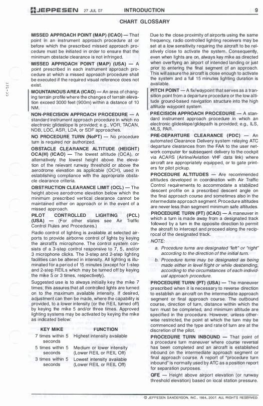
MISSED APPROACH POINT (MAP) (ICAO) - That point in an instrument approach procedure at or before which the prescribed missed approach procedure must be initiated in order to ensure that the minimum obstacle clearance is not infringed. MISSED APPROACH POINT (MAP) (USA) - A point prescribed in each instrument approach procedure at which a missed approach procedure shall be executed if the required visual reference does not exist. MOUNTAINOUS AREA (ICAO) - An area of changing terrain profile where the changes of terrain elevation exceed 3000 feet (900m) within a distance of 1 0 NM. NON-PRECISION APPROACH PROCEDURE - A standard instrument approach procedure in which no electronic glideslope is provided; e.g. , VOR, TACAN, NOB, LOC, ASR, LOA, or SDF approaches. NO PROCEDURE TURN (NoPT) - No procedure turn is required nor authorized. OBSTACLE CLEARANCE ALTITUDE (HEIGHT) OCA(H) (ICAO) - The lowest altitude (OCA), or alternatively the lowest height above the elevation of the relevant runway threshold or above the aerodrome elevation as applicable (OCH), used in establishing compliance with the appropriate obstacle clearance criteria. OBSTRUCTION CLEARANCE LIMIT (OCL) - The height above aerodrome elevation below which the minimum prescribed vertical clearance cannot be maintained either on approach or in the event of a missed approach. PILOT CONTROLLED LIGHTING (PCL) (USA) - (For other states see Air Traffic Control Rules and Procedures.) Radio control of lighting is available at selected airports to provide airborne control of lights by keying the aircraft's microphone. The control system consists of a 3-step control responsive to 7, 5, and/or 3 microphone clicks. The 3-step and 2-step lighting facilities can be altered in intensity. All lighting is illuminated for a period of 15 minutes (except for I -step and 2-step REILs which may be turned off by keying the mike 5 or 3 times, respectively). Suggested use is to always initially key the mike 7 times; this assures that all controlled lights are turned on to the maximum available intensity. If desired, adjustment can then be made, where the capability is provided, to a lower intensity (or the REIL turned off) by keying the mike 5 and/or three times. Approved lighting systems may be activated by keying the mike as indicated below:
KEY MIKE FUNCTION 7 times within 5 Highest intensity available
seconds 5 times within 5
seconds 3 times within 5
seconds
Medium or lower intensity (Lower REIL or REIL Off) Lowest intensity available (Lower REIL or REIL Off)
Due to the close proximity of airports using the same frequency, radio controlled lighting receivers may be set at a low sensitivity requiring the aircraft to be relatively close to activate the system. Consequently, even when lights are on, always key mike as directed when overflying an airport of intended landing or just prior to entering the final segment of an approach. This will assure the aircraft is close enough to activate the system and a full 1 5 minutes lighting duration is available. PITCH POINT - A fixfwaypoint that serves as a transition point from a departure procedure or the low altitude ground-based navigation structure into the high altitude waypoint system. PRECISION APPROACH PROCEDURE - A standard instrument approach procedure in which an electronic glideslope/glidepath is provided; e.g., ILS, MLS, PAR. PRE-DEPARTURE CLEARANCE (PDC) - An automated Clearance Delivery system relaying ATC departure clearances from the FAA to the user network computer for subsequent delivery to the cockpit via ACARS (Airline/Aviation VHF data link) where aircraft are appropriately equipped, or to gate printers for pilot pickup. PROCEDURE ALTITUDES - Are recommended altitudes developed in coordination with Air Traffic Control requirements to accommodate a stabilized descent profile on a prescribed descent angle on the final approach course and sometimes also in the intermediate approach segment. Procedure altitudes are never less than segment minimum safe altitudes. PROCEDURE TURN (PT) (ICAO) - A maneuver in which a turn is made away from a designated track followed by a turn in the opposite direction to permit the aircraft to intercept and proceed along the reciprocal of the designated track. NOTE:
a. Procedure turns are designated "left" or "right" according to the direction of the initial turn.
b. Procedure turns may be designated as being made either in level flight or while descending, according to the circumstances of each individual approach procedure.
PROCEDURE TURN (PT) (USA) - The maneuver prescribed when it is necessary to reverse direction to establish an aircraft on the intermediate approach segment or final approach course. The outbound course, direction of turn, distance within which the turn must be completed, and minimum altitude are specified in the procedure. However, unless otherwise restricted, the point at which the turn may be commenced and the type and rate of turn are at the discretion of the pilot. PROCEDURE TURN INBOUND - That point of a procedure turn maneuver where course reversal has been completed and an aircraft is established inbound on the intermediate approach segment or final approach course. A report of "procedure turn inbound" is normally used by ATC as a position report for separation purposes. QFE - Height above airport elevation (or runway threshold elevation) based on local station pressure.
© JEPPESEN SANDERSON, INC., 1984, 2007. ALL RIGHTS RESERVED.
1 0 INTRODUCTION 27 JUL 07 :=.JEPPESEN CHART GLOSSARY
QNE - Altimeter setting 29.92 inches of mercury, 101 3.2 hectopascals or 1 01 3.2 millibars. QNH - Altitude above mean sea level based on local station pressure. RACETRACK PROCEDURE (ICAO) - A procedure designed to enable the aircraft to reduce altitude during the initial approach segment and/or establish the ai rcraft inbound when the entry into a reversal procedure is not practical. RADAR WEATHER ECHO INTENSITY LEVELS - Existing radar systems cannot detect turbulence. However, there is a direct correlation between the degree of turbulence and other weather features associated with thunderstorms and the radar weather echo intensity. The National Weather Service has categorized radar weather echo intensity for precipitation into six levels. These levels are sometimes expressed during communications as "VIP LEVEL:' 1 through 6 (derived from the component of the radar that produces the information -Video Integrator and Processor). The following list gives the "VIP LEVELS" in relation to the precipitation intensity within a thunderstorm:
Level 1 . WEAK Level 2. MODERATE Level 3. STRONG Level 4. VERY STRONG Level 5. INTENSE Level 6. EXTREME
RADIO ALTIMETER / RADAR ALTIMETER - Aircraft equipment which makes use of the reflection of radio waves from the ground to determine the height of the aircraft above the surface. RAPID EXIT TAXIWAY (ICAO) - A taxiway connected to a runway at an acute angle and designed to allow landing airplanes to turn off at higher speeds than are achieved on other exit taxiways thereby minimizing runway occupancy times. REDUCED VERTICAL SEPARATION MINIMUMS (RVSM) - A reduction in the vertical separation between flight levels 290 - 410 from 2000 to 1 000 feet. REQUIRED NAVIGATION PERFORMANCE (RNP) - A statement of navigation position accuracy necessary for operation within a defined airspace. RNP is performance-based and not dependent on a specific piece of equipment. RNP includes a descriptive number, the value being an indicator of the size of the containment area (e.g., RNP-0.3, RNP- 1 , RNP-3, etc.). The different values are assigned to terminal, departure, and enroute operations. Some aircraft have RNP approval in their AFM without a GPS sensor. The lowest level of sensors that the FAA will support for RNP service is DME/DME. However, necessary DME signal may not be available at the airport of intended operations. For those locations having an RNAV chart published with LNAVIVNAV minimums, a procedure note may be provided such as "DME/DME RNP-0.3 NA." This means that RNP aircraft dependent on DME/DME to achieve RNP-0.3 are not authorized to conduct this approach. Where
DME facility availability is a factor, the note may read "DME/DME RNP-0.3 authorized; ABC and XYZ required. " This means that ABC and XYZ facilities have been determined by flight inspection to be required in the navigation solution to assure RNP-0.3. VOR/DME updating must not be used for approach procedures. RNAV APPROACH - An instrument approach procedure which relies on aircraft area navigation equipment for navigation guidance. ROUTE MINIMUM OFFROUTE ALTITU DE (Route MORA) - This is an altitude derived by Jeppesen. The Route MORA altitude provides reference point clearance within 10 NM of the route centerline (regardless of the route width) and end fixes. Route MORA values clear all reference points by 1 000 feet in areas where the highest reference points are 5000 feet MSL or lower. Route MORA values clear all reference points by 2000 feet in areas where the highest reference points are 5001 feet MSL or higher. When a Route MORA is shown along a route as "unknown" it is due to incomplete or insufficient information. RUNWAY EDGE LIGHTS (ICAO) - Are provided for a runway intended for use at night or for a precision approach runway intended for use by day or night. Runway edge lights shall be fixed lights showing variable white, except that:
a. in the case of a displaced threshold, the lights between the beginning of the runway and the displaced threshold shall show red in the approach direction; and
b. a section of the lights 600m or one-third of the runway length, whichever is the less, at the remote end of the runway from the end at which the takeoff run is started, may show yellow.
RUNWAY EDGE LIGHTS (USA) - Lights used to outline the edges of runways during periods of darkness or restricted visibility conditions. The light systems are classified according to the intensity or brightness they are capable of producing: they are the H igh Intensity Runway Lights (H IRL), Medium I ntensity Runway Lights (MIRL), and the Low Intensity Runway Lights (RL). The H IRL and MI RL systems have variable intensity controls, where the RLs normally have one intensity setting.
a. The runway edge lights are white, except on instrument runways amber replaces white on the last 2000 feet or half of the runway length, whichever is less, to form a caution zone for landings.
b. The lights marking the ends of the runway emit red light toward the runway to indicate the end of runway to a departing aircraft and emit green outward from the runway end to indicate the threshold to landing aircraft.
RUNWAY MARKINGS -
a. Basic marking - Markings on runways used for operations under visual flight rules consisting of centerline markings and runway direction numbers and, if required, letters.
© JEPPESEN SANDERSON, INC., 1984, 2007. ALL RIGHTS RESERVED.
==.JEPPESEN 27 JUL 07 INTRODUCTION 1 1
CHART GLOSSARY
b. Instrument marking - Markings on runways served by nonvisual navigation aids and intended for landings under instrument weather conditions, consisting of basic marking plus threshold markings.
c. All-weather (precision instrument) marking -Marking on runways served by nonvisual precision approach aids and on runways having special operational requirements, consisting of instrument markings plus landing zone markings and side strips.
SEGMENT MINIMUM ALTITUDE (SMA), or SEGMENT MINIMUM SAFE ALTITUDE (SMSA) - An altitude that provides minimum obstacle clearance in each segment of a non-precision approach. Segment minimum (safe) altitudes can be considered "do not descend below" altitudes and can be lower than procedure altitudes which are specifically developed to facilitate a constant rate or stabilized descent. SEGMENTS OF AN INSTRUMENT APPROACH PROCEDURE - An instrument approach procedure may have as many as four separate segments depending on how the approach procedure is structured. ICAO -
a. Initial Approach - That segment of an instrument approach procedure between the initial approach fix and the intermediate approach fix or, where applicable, the final approach fix or point.
b. Intermediate Approach - That segment of an instrument approach procedure between either the intermediate approach fix and the final approach fix or point, or between the end of a reversal, race track or dead reckoning track procedure and the final approach fix or point, as appropriate.
c. Final Approach - That segment of an instrument approach procedure in which alignment and descent for landing are accomplished.
d. Missed Approach Procedure - The procedure to be followed if the approach cannot be continued.
USA -a. Initial Approach - The segment between the
initial approach fix and the intermediate fix or the point where the aircraft is established on the intermediate course or final course.
b. Intermediate Approach - The segment between the intermediate fix or point and the final approach fix.
c. Final Approach - The segment between the final approach fix or point and the runway, airport or missed approach point.
d. Missed Approach - The segment between the missed approach point, or point of arrival at decision height, and the missed approach fix at the prescribed altitude.
SELECTIVE CALL SYSTEM (SELCAL) - A system which permits the selective calling of individual aircraft over radiotelephone channels linking a ground station with the aircraft.
SIDESTEP MANEUVER - A visual maneuver accomplished by a pilot at the completion of an instrument approach to permit a straight-in landing on a parallel runway not more than 1 200 feet to either side of the runway to which the instrument approach was conducted. SPECIAL USE AIRSPACE - Airspace of defined dimensions identified by an area on the surface of the earth wherein activities must be confined because of their nature and/or wherein limitations may be imposed upon aircraft operations that are not a part of those activities. Types of special use airspace are:
a. Alert Area (USA) - Airspace which may contain a high volume of pilot training activities or an unusual type of aerial activity, neither of which is hazardous to aircraft. Alert Areas are depicted on aeronautical charts for the information of nonparticipating pilots. All activities within an Alert Area are conducted in accordance with Federal Aviation Regulations, and pilots of participating aircraft as well as pilots transiting the area are equally responsible for collision avoidance.
b. Controlled Firing Area (USA) - Airspace wherein activities are conducted under conditions so controlled as to eliminate hazards to nonparticipating aircraft and to ensure the safety of persons and property on the ground.
c. Military Operations Area (MOA) (USA) - A MOA is airspace established outside of a C lass "A" airspace area to separate or segregate certain nonhazardous military activities from IFR traffic and to identify for VFR traffic where these activities are conducted.
d. Prohibited Area - Airspace designated under FAR Part 73 within which no person may operate an aircraft without the permission of the using agency.
e. Restricted Area (USA) - Airspace designated under Part 73, within which the flight of aircraft, while not wholly prohibited, is subject to restriction. Most restricted areas are designated joint use and IFRNFR operations in the area may be authorized by the controlling ATC facility when it is not being utilized by the using agency. Restricted areas are depicted on enroute charts. Where joint use is authorized, the name of the ATC contrOlling facility is also shown.
f. Restricted Area (ICAO) - An airspace of defined dimensions, above the land areas or territorial waters of a state, within which the flight of aircraft is restricted in accordance with certain specified coordinates.
g. Warning Area - A warning area is airspace of defined dimensions from 3 nautical miles outward from the coast of the United States, that contains activity that may be hazardous to nonparticipating aircraft. The purpose of such warning areas is to warn nonparticipating pilots of the potential danger. A warning area may be located over domestic or international waters or both.
Cl JEPPESEN SANDERSON. INC . • '984. 2007. ALL RIGHTS RESERVED.
1 2 INTRODUCTION 27 JUL 07 ==JEPPESEN CHART GLOSSARY
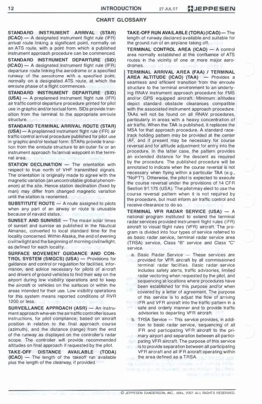
STANDARD INSTRUMENT ARRIVAL (STAR) (ICAO) - A designated instrument flight rule ( IFR) arrival route linking a significant point, normally on an ATS route, with a point from which a published instrument approach procedure can be commenced. STANDARD INSTRUMENT DEPARTURE (SID) (ICAO) - A designated instrument flight rule (IFR) departure route linking the aerodrome or a specified runway of the aerodrome with a specified point, normally on a designated ATS route, at which the en route phase of a flight commences. STANDARD INSTRUMENT DEPARTURE (SID) (USA) - A preplanned instrument flight rule (I FR) air traffic control departure procedure printed for pilot use in graphic and/or textual form. SIDs provide transition from the terminal to the appropriate enroute structure. STANDARD TERMINAL ARRIVAL ROUTE (STAR) (USA) - A preplan ned instrument flight rule (I FR) air traffic control arrival procedure published for pilot use in graphic and/or textual form. STARs provide transition from the enroute structure to an outer fix or an instrument approach fix/arrival waypoint in the terminal area. STATION DECLINATION - The orientation with respect to true north of VHF transmitted signals. The orientation is originally made to agree with the magnetic variation (an uncontrollable global phenomenon) at the site. Hence station declination (fixed by man) may differ from changed magnetic variation until the station is reoriented. SUBSTITUTE ROUTE - A route assigned to pilots when any part of an airway or route is unusable because of navaid status. SUNSET AND SUNRISE - The mean solar times of sunset and sunrise as published in the Nautical Almanac, converted to local standard time for the locality concerned. Within Alaska, the end of evening civil twilight and the beginning of morning civil twilight, as defined for each locality. SURFACE MOVEMENT GUIDANCE AND CONTROL SYSTEM (SMGCS) (USA) - Provisions for guidance and control or regulation for facilities, information, and advice necessary for pilots of ai rcraft and drivers of ground vehicles to find their way an the airport during low visibility operations and to keep the aircraft or vehicles on the surfaces or within the areas intended for their use. Low visibility operations for this system means reported conditions of RVR 1 200 or less. SURVEILLANCE APPROACH (ASR) - An instrument approach wherein the air traffic controller issues instructions, for pilot compliance, based on aircraft position in relation to the final approach course (azimuth) , and the distance (range) from the end of the runway as displayed on the controller's radar scope. The controller will provide recommended altitudes on final approach if requested by the pilot. TAKE-OFF DISTANCE AVAILABLE (TODA) (ICAO) - The length of the takeoff run available plus the length of the clearway, if provided.
TAKE-OFF RUN AVAILABLE (TORA) (ICAO) - The length of runway declared available and suitable for the ground run of an airplane taking off. TERMINAL CONTROL AREA (ICAO) - A control area normally established at the confluence of ATS routes in the vicinity of one or more major aerodromes. TERMINAL ARRIVAL AREA (FAA) / TERMINAL AREA ALTITUDE (ICAO) (TAA) - Provides a seamless and efficient transition from the en route structure to the terminal environment to an underlying RNAV instrument approach procedure for FMS and/or GPS equipped aircraft. Minimum altitudes depict standard obstacle clearances compatible with the associated instrument approach procedure. TAAs will not be found on all RNAV procedures, particularly in areas with a heavy concentration of air traffic. When the TAA is published, it replaces the MSA for that approach procedure. A standard racetrack holding pattern may be provided at the center IAF, and if present may be necessary for course reversal and for altitude adjustment for entry into the procedure. In the latter case, the pattern provides an extended distance for the descent as required by the procedure. The published procedure will be annotated to indicate when the course reversal is not necessary when flying within a particular TAA (e.g., "NoPT"). Otherwise, the pilot is expected to execute the course reversal under the provisions of 1 4 CFR Section 9 1 . 1 75 (USA). The pilot may elect to use the course reversal pattern when it is not required by the procedure, but must inform air traffic control and receive clearance to do so. TERMINAL VFR RADAR SERVICE (USA) - A national program instituted to extend the terminal radar services provided instrument flight rules ( I FR) aircraft to visual flight rules (VFR) aircraft. The program is divided into four types of service referred to as basic radar service, terminal radar service area (TRSA) service, Class "B" service and Class "C" service.
a. Basic Radar Service - These services are provided for VFR aircraft by all commissioned terminal radar facilities. Basic radar service includes safety alerts, traffic advisories, limited radar vectoring when requested by the pilot, and sequencing at locations where procedures have been established for this purpose and/or when covered by a letter of agreement. The purpose of this service is to adjust the flow of arriving I FR and VFR aircraft into the traffic pattern in a safe and orderly manner and to provide traffic advisories to departing VFR aircraft.
b. TRSA Service - This service provides, in addition to basic radar service, sequencing of all IFR and participating VFR aircraft to the primary airport and separation between all participating VFR aircraft. The purpose of this service is to provide separation between all participating VFR aircraft and all lFR aircraft operating within the area defined as a TRSA.
© JEPPESEN SANDERSON. INC .• 1984. 2007. ALL RIGHTS RESERVED.

w w .-. '" '"
::.JEPPESEN 27 JUL 07 INTRODUCTION 1 3
CHART GLOSSARY
c. Class "8" Service - This service provides, in addition to basic radar service, approved separation of aircraft based on IFR, VFR, and/or weight, and sequencing of VFR arrivals to the primary airport(s).
d. Class "C" Service - This service provides, in addition to basic radar service, approved separation between IFR and VFR aircraft, and sequencing of VFR aircraft, and sequencing of VFR arrivals to the primary airport.
TERMINAL RADAR SERVICE AREA (TRSA) (USA) - Airspace surrounding designated airports wherein ATC provides radar vectoring, sequencing and separation on a full-time basis for all IFR and participating VFR aircraft. Service provided in a TRSA is called Stage I I I Service. Pilots' participation is urged but is not mandatory. THRESHOLD - The beginning of that portion of the runway usable for landing. THRESHOLD CROSSING HEIGHT - The theoretical height above the runway threshold at which the aircraft's glideslope antenna would be if the aircraft maintains the trajectory established by the mean ILS glideslope or MLS glidepath. I TOUCHDOWN ZONE ELEVATION (TDZE) - The highest elevation in the first 3000 feet of the landing surface. TRANSITION ALTITUDE (QNH) - The altitude in the vicinity of an airport at or below which the vertical position of an aircraft is controlled by reference to altitudes (MSL). TRANSITION HEIGHT (QFE) - The height in the vicinity of an airport at or below which the vertical position of an aircraft is expressed in height above the airport reference datum. TRANSITION LAYER - The airspace between the transition altitude and the transition level. Aircraft descending through the transition layer will use altimeters set to local station pressure, while departing aircraft climbing through the layer will be using standard altimeter setting (ONE) of 29.92 inches of Mercury, 1 01 3.2 millibars, or 101 3.2 hectopascals. TRANSITION LEVEL (QNE) - The lowest flight level available for use above the transition altitude. TURN ANTICIPATION - Turning maneuver initiated prior to reaching the actual airspace fix or turn point that is intended to keep the aircraft within established airway or route boundaries. VERTICAL NAVIGATION (VNAV) - That function of RNAV equipment which provides guidance in the vertical plane. VERTICAL PATH ANGLE (VPA) (USA) - The descent angle shown on some non-precision approaches describing the geometric descent path from the Final approach fix (FAF), or on occasion from an intervening stepdown fix, to the Threshold Crossing Height (TCH). This angle may or may not coincide with the angle projected by a Visual Glide Slope Indicator (VASI , PAPI , PLASI , etc.)
VISIBILITY (ICAO) - The ability, as determined by atrnospheric conditions and expressed in units of distance, to see and identify prominent unlighted objects by day and prominent lighted objects by night.
a. Flight Visibility - The visibility forward from the cockpit of an aircraft in flight.
b. Ground Visibility - The visibility at an aerodrome as reported by an accredited observer.
c. Runway Visual Range (RVR) - The range over which the pilot of an aircraft on the centerline of a runway can see the runway surface markings or the lights delineating the runway or identifying its centerline.
VISIBILITY (USA) - The ability, as determined by atmospheric conditions and expressed in units of distance, to see and identify prominent unlighted objects by day and prominent lighted objects by night. Visibility is reported as statute or nautical miles, hundreds of feet or meters.
a. Flight Visibility - The average forward horizontal distance, from the cockpit of an aircraft in flight, at which prominent unlighted objects may be seen and identified by day and prominent lighted objects may be seen and identified by night.
b. Ground Visibility - Prevailing horizontal visibility near the earth's surface as reported by the United States National Weather Service or an accredited observer.
c. Prevailing Visibility - The greatest horizontal visibility equaled or exceeded throughout at least half the horizon circle which need not necessarily be continuous.
d. Runway Visibility Value (RW) - The visibility determined for a particular runway by a transmissometer. A meter provides a continuous indication of the visibility (reported in miles or fractions of miles) for the runway. RVV is used in lieu of prevailing visibility in determining minimums for a particular runway.
e. Runway Visual Range (RVR) - An instrumentally derived value, based on standard calibrations, that represents the horizontal distance a pilot will see down the runway from the approach end; it is based on the sighting of either high intensity runway lights or on the visual contrast of other targets whichever yields the greater visual range. RVR, in contrast to prevailing or runway visibil ity, is based on what a pilot in a moving aircraft should see looking down the runway. RVR is horizontal visual range, not slant visual range. It is based on the measurement of a transmissometer made near the touchdown point of the instrument runway and is reported in hundreds of feet. RVR is used in lieu of RVV andlor prevailing visibility in determining minimums for a particular runway.
1 . Touchdown RVR - The RVR visibility readout values obtained from RVR equipment serving the runway touchdown zone.
2. Mid-RVR - The RVR readout values obtained from RVR equipment located midfield of the runway.
© JEPPESEN SANOERSON, INC .. 1984. 2007. ALL RIGHTS RESERVED.
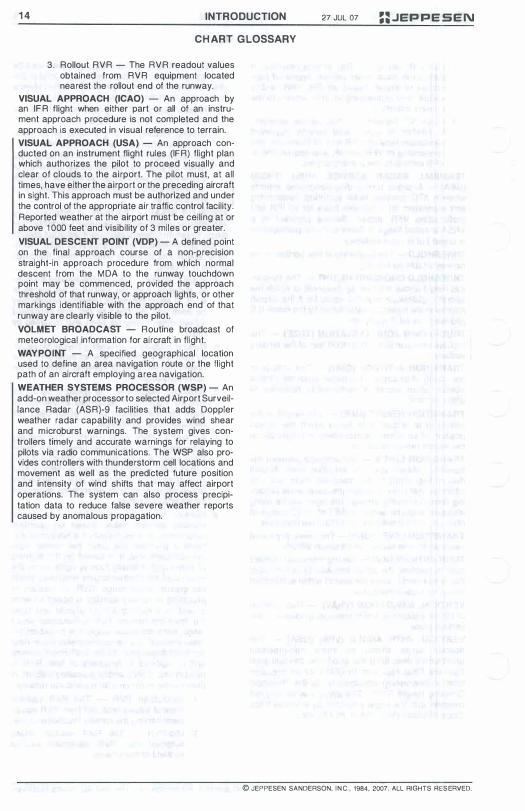
1 4 INTRODUCTION
CHART GLOSSARY
3. Rollout RVR - The RVR readout values obtained from RVR equipment located nearest the rollout end of the runway.
VISUAL APPROACH (ICAO) - An approach by an IFR flight when either part or all of an instrument approach procedure is not completed and the approach is executed in visual reference to terrain. VISUAL APPROACH (USA) - An approach conducted on an instrument flight rules (IFR) flight plan which authorizes the pilot to proceed visually and clear of clouds to the airport. The pilot must, at all times, have either the airport or the preceding aircraft in sight. T his approach must be authorized and under the control of the appropriate air traffic control facility. Reported weather at the airport must be ceiling at or above 1 000 feet and visibility of 3 miles or greater. VISUAL DESCENT POINT (VDP) - A defined point on the final approach course of a non-precision straight-in approach procedure from which normal descent from the MDA to the runway touchdown point may be commenced, provided the approach threshold of that runway, or approach lights, or other markings identifiable with the approach end of that runway are clearly visible to the pilot. VOLMET BROADCAST - Routine broadcast of meteorological information for aircraft in flight. WAY POINT - A specified geographical location used to define an area navigation route or the flight path of an aircraft employing area navigation. WEATHER SYSTEMS PROCESSOR (WSP) - An add-on weather processor to selected Airport Surveillance Radar (ASR)-9 facilities that adds Doppler weather radar capability and provides wind shear and microburst warnings. The system gives controllers timely and accurate warnings for relaying to pilots via radio communications. The WSP also provides controllers with thunderstorm cell locations and movement as well as the predicted future position and intenSity of wind shifts that may affect airport operations. T he system can also process precipitation data to reduce false severe weather reports caused by anomalous propagation.
27 JUL 07 ::JEPPESEN
© JEPPESEN SANDERSON. INC .. 1984. 2007. ALL RIGHTS RESERVED.

==.JEPPE SEN 27 JUl 07 INTRODUCTION 41
ABBREVIATIONS USED IN AIRWAY MANUAL
DEFINITIONS
AlA Air to Air AAF Army Air Field AAIM Aircraft Autonomous Integrity
Monitoring AAIS Automated Aerodrome Information
Service AAL Above Aerodrome Level AAS Airport Advisory Service AB Air Base ABM Abeam ABN Aerodrome Beacon AC Air Carrier ACA Arctic Control Area ACA Approach Control Area ACAS Airborne Collision Avoidance
System ACARS Airborne Communications
Addressing and Reporting System ACC Area Control Center ACFT Aircraft ACN Aircraft Classification Number AD Aerodrome ADA Advisory Area ADF Automatic Direction Finding ADIZ Air Defense Identification Zone ADR Advisory Route ADS Automatic Dependent Surveillance ADV Advisory Area AEIS Aeronautical Enroute Information
Service AER Approach End of Runway AERADIO Air Radio AERO Aerodrome AF Aux Air Force Auxiliary Field AFB Air Force Base AFIS Aerodrome Flight Information
Service AFN American Forces Network AFRS Armed Forces Radio Stations AFRU Aerodrome Frequency Response
Unit AFS Air Force Station AFSS Automated Flight Service Station A/G Air-to-Ground AGL Above Ground Level AGNIS Azimuth Guidance Nose-in-Stand AH Alert Height AHP Army Heliport AIRAC Aeronautical Information
Regulation and Control AIREP Air-Report AIS Aeronautical Information Services
ALA Aircraft Landing Area ALF Auxiliary Landing Field ALT Altitude ALTN Alternate AMA Area Minimum Altitude AMSL Above Mean Sea Level ANGB Air National Guard Base AOE Airport/Aerodrome of Entry AOR Area of Responsibility APAPI Abbreviated Precision Approach
Path Indicator APC Area Positive Control APCH Approach APP Approach Control APT Airport APV Approach Procedure with Vertical
Guidance ARB Air Reserve Base ARINC Aeronautical Radio, Inc. ARO Aerodrome Reporting Officer ARP Airport Reference Point ARR Arrival ARTCC Air Route Traffic Control Center ASDA Accelerate Stop Distance Available ASOS Automated Surface Observing
System ASR Airport Surveillance Radar ATA Actual Time of Arrival ATCAA Air Traffic Control Assigned
Airspace ATCC Air Traffic Control Center ATCT Air Traffic Control Tower ATD Actual Time of Departure ATF Aerodrome Traffic Frequency ATFM Air Traffic Flow Management ATIS Automatic Terminal Information
Service ATS Air Traffic Service ATZ Aerodrome Traffic Zone AUTH Authorized AUW All-up Weight AUX Auxiliary AVBL Available AWIB Aerodrome Weather Information
Broadcast AWlS Aerodrome Weather Information
Service AWOS Automated Weather Observing
System AWSS Aviation Weather Sensor System AWY Airway AZM Azimuth Baro VNAV Barometric Vertical Navigation BC Back Course
© JEPPESEN SANDERSON, INC., 1984, 2007. ALL RIGHTS RESERVED.
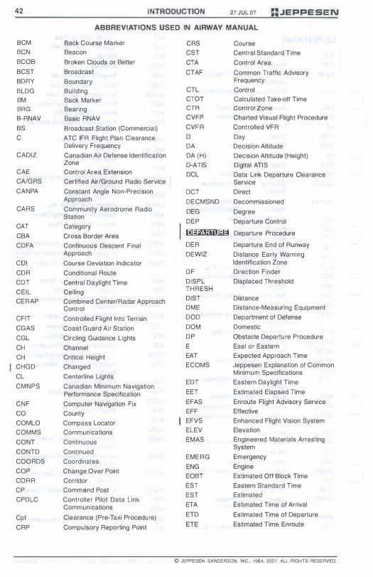
42 I NTRODUCTION 27 JUL 07 :=.JEPPESEN ABBREVIATIONS USED IN AIRWAY MANUAL
BCM Back Course Marker CRS Course BCN Beacon CST Central Standard Time BCOB Broken Clouds or Better CTA Control Area BCST Broadcast CTAF Common Traffic Advisory BDRY Boundary Frequency BLDG Building CTL Control BM Back Marker CTOT Calculated Take-off Time BRG Bearing CTR Control Zone B-RNAV Basic RNAV CVFP Charted Visual Flight Procedure BS Broadcast Station (Commercial) CVFR Controlled VFR C ATC IFR Flight Plan Clearance 0 Day
Delivery Frequency DA Decision Altitude CADIZ Canadian Air Defense Identification DA (H) Decision Altitude (Height)
Zone D-ATIS Digital ATIS CAE Control Area Extension DCL Data Link Departure Clearance CAlGRS Certified Air/Ground Radio Service Service CANPA Constant Angle Non-Precision OCT Direct
Approach DECMSND Decommissioned CARS Community Aerodrome Radio DEG Degree Station CAT Category DEP Departure Control
CBA Cross Border Area Iol::l:H;UlI@ Departure Procedure CDFA Continuous Descent Final DER Departure End of Runway
Approach DEWIZ Distance Early Warning COl Course Deviation Indicator Identification Zone CDR Conditional Route OF Direction Finder COT Central Daylight Time DISPL Displaced Threshold CEIL Ceiling THRESH CERAP Combined Center/Radar Approach DIST Distance
Control DME Distance-Measuring Equipment CFIT Controlled Flight Into Terrain DOD Department of Defense CGAS Coast Guard Air Station DaM Domestic CGL Circling Guidance Lights DP Obstacle Departure Procedure CH Channel E East or Eastern CH Critical Height EAT Expected Approach Time CHGD Changed ECOMS Jeppesen Explanation of Common CL Centerline Lights Minimum Specifications
CMNPS Canadian Minimum Navigation EDT Eastern Daylight Time Performance Specification EET Estimated Elapsed Time
CNF Computer Navigation Fix EFAS Enroute Flight Advisory Service CO County EFF Effective COMLO Compass Locator EFVS Enhanced Flight Vision System COMMS Communications ELEV Elevation CO NT Continuous EMAS Engineered Materials Arresting CONTD Continued System
COORDS Coordinates EMERG Emergency
COP Change Over Point ENG Engine
CORR Corridor EOBT Estimated Off Block Time
CP Command Post EST Eastern Standard Time
CPDLC Controller Pilot Data Link EST Estimated Communications ETA Estimated Time of Arrival
Cpt Clearance (Pre-Taxi Procedure) ETD Estimated Time of Departure
CRP Compulsory Reporting Point ETE Estimated Time Enroute
© JEPPESEN SANDERSON, INC., 1964, 2007. ALL RIGHTS RESERVED.

==JEPPESEN 27 JUL 07 INTRODUCTION 43
ABBREVIATIONS USED IN AIRWAY MANUAL
ETOPS Extended Range Operation with H Non-Directional Radio Beacon or two-engine airplanes High Altitude
EVS Enhanced Vision System H24 24 Hour Service FAA Federal Aviation Administration HAA Height Above Airport FACF Final Approach Course Fix HALS High Approach Landing System FAF Final Approach Fix HAS Height Above Site FAIL Failure HAT Height Above Touchdown FANS Future Air Navigation System HC Critical Height FAP Final Approach Point HOG Heading FAR Federal Aviation Regulation H F High Frequency (3-30 MHz) FAT Final Approach Track HGS Head-up Guidance System FATO Final Approach and Take-off Area HI High (altitude) FCP Final Control Point H I High Intensity (lights) FIC Flight Information Center H IALS High Intensity Approach Light FIR Flight Information Region System FIS Flight Information Service H IRL High Intensity Runway Edge Lights FL Flight Level (Altitude) HIWAS Hazardous Inflight Weather FLO Field Advisory Service
FLG Flashing HJ Sunrise to Sunset
FLT Flight HN Sunset to Sunrise
FM Fan Marker HO By Operational Requirements
FMC Flight Management Computer hPa Hectopascal (one hectopascal =
one mill ibar) FMS Flight Management System H R Hours (period o f time) FPM Feet Per Minute HS During Hours of Scheduled FPR Flight Planning Requirements Operations FREQ Frequency HST High Speed Taxiway Turn-off FSS Flight Service Station HUD Head-up Display FT Feet HUDLS Head-Up Display Landing System FTS Flexible Track System HX No Specific Working Hours G Guards only (radio frequencies) Hz Hertz (cycles per second) GA General Aviation Island GBAS Ground-Based Augmentation lAC Instrument Approach Chart
System IAF Initial Approach Fix GCA Ground Controlled Approach IAML Integrity Monitor Alarm (radar) GCO Ground Communication Outlet lAP Instrument Approach Procedure
GEN General lAS Indicated Airspeed
GLONASS Global Orbiting Navigation Satellite lATA International Air Transport System Association
GLS Global Navigation Satellite System IAWP Initial Approach Waypoint
[GNSS] Landing System IBN Identification Beacon GMT Greenwich Mean Time ICAO International Civil Aviation GND Ground Control Organization
GND Surtace of the Earth (either land IDENT Identification or water) I F Intermediate Fix
GNSS Global Navigation Satellite System IFBP Inflight Broadcast Procedure GP Glidepath I FR Instrument Flight Rules GPS Global Positioning System IGS Instrument Guidance System GPWS Ground Proximity Warning System I LS Instrument Landing System GS Glide Slope 1M Inner Marker GIS Ground Speed IMAL Integrity Monitor Alarm GWT Gross Weight IMC Instrument Meteorological
Conditions IMTA Intensive Military Training Area
© JEPPESEN SANDERSON, INC., 1984, 2007. ALL RIGHTS RESERVED.
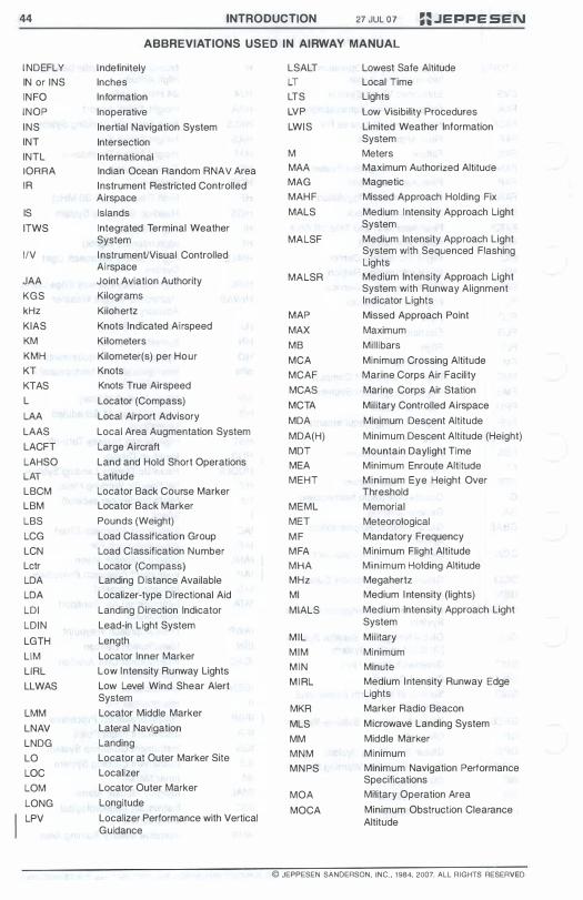
44 INTRODUCTION 27 JUL 07 ::JEPPESEN ABBREVIATIONS USED IN AIRWAY MANUAL
INDEFLY Indefinitely LSALT Lowest Safe Altitude IN or INS Inches LT Local Time INFO Information LT S Lights INOP Inoperative LVP Low Visibility Procedures INS Inertial Navigation System LWIS Limited Weather Information INT Intersection System INTL International M Meters IORRA Indian Ocean Random RNAV Area MAA Maximum Authorized Altitude IR Instrument Restricted Controlled MAG Magnetic
Airspace MAHF Missed Approach Holding Fix IS Islands MALS Medium Intensity Approach Light ITWS Integrated Terminal Weather System
System MALSF Medium Intensity Approach Light IIV I nstrumenVVisual Controlled System with Sequenced Flashing
Airspace Lights JAA Joint Aviation Authority MALSR Medium Intensity Approach Light KGS Kilograms System with Runway Alignment
Indicator Lights kHz Kilohertz MAP Missed Approach Point KIAS Knots Indicated Airspeed MAX Maximum KM Kilometers MB Mill ibars KMH Kilometer(s) per Hour MCA Minimum Crossing Altitude KT Knots MCAF Marine Corps Air Facility KTAS Knots True Airspeed MCAS Marine Corps Air Station L Locator (Compass) MCTA Military Controlled Airspace LAA Local Airport Advisory MDA Minimum Descent Altitude LAAS Local Area Augmentation System MDA(H) Minimum Descent Altitude (Height) LACFT Large Aircraft MDT Mountain Daylight Time LAHSO Land and Hold Short Operations MEA Minimum Enroute Altitude LAT Latitude MEHT Minimum Eye Height Over LBCM Locator Back Course Marker Threshold LBM Locator Back Marker MEML Memorial LBS Pounds (Weight) MET Meteorological LCG Load Classif ication Group M F Mandatory Frequency LCN Load Classification Number MFA Minimum Flight Altitude Lctr Locator (Compass) MHA Minimum Holding Altitude LOA Landing D istance Available MHz Megahertz LOA Localizer-type Directional Aid MI Medium I ntensity (lights) LDI Landing Direction Indicator MIALS Medium Intensity Approach Light LDIN Lead-in Light System System LGTH Length MIL Mil itary LIM Locator Inner Marker MIM Minimum LlRL Low Intensity Runway Lights M IN Minute LLWAS Low Level Wind Shear Alert M I RL Medium Intensity Runway Edge
System Lights LMM Locator Middle Marker MKR Marker Radio Beacon
LNAV Lateral Navigation MLS Microwave Landing System LNDG Landing MM Middle Marker LO Locator at Outer Marker Site MNM Minimum LOC Localizer MNPS Minimum Navigation Performance
LOM Locator Outer Marker Specifications
MOA Military Operation Area LONG Longitude MOCA Minimum Obstruction Clearance LPV Localizer Performance with Vertical Altitude
Guidance
© JEPPESEN SANOERSON. INC .• 1984. 2007 ALL RIGHTS RESERVED

==.JEPPESEN 27 JUL 07 INTRODUCTION 45
ABBREVIATIONS USED IN AIRWAY MANUAL
MORA Minimum Off-Route Altitude (Grid OM Outer Marker or Route) OPS Operations or Operates
MRA Minimum Reception Altitude OIR On Request MBA M\nirnuTTl Safe/Sector A\ti.tude orr Other Times MSL Mean Sea Level OTR Oceanic Transition Route MST Mountain Standard Time OTS Out-of-Service MTA Military Training Area PA Precision Approach MTAF Mandatory Traffic Advisory PAL Pilot Activated Lighting w Frequency PANS-OPS Procedures for Air Navigation w
0 Minimum Terrain Clearance Services - Aircraft Operations , MTCA '"
'" Altitude PAPI Precision Approach Path Indicator MTMA Military Terminal Control Area PAR Precision Approach Radar MTOW Maximum Take-off Weight PCL Pilot Controlled Lighting MUN Municipal PCN Pavement Classification Number MVA Minimum Vectoring Altitude PCZ Positive Control Zone N Night, North or Northern PDC Pre-Departure Clearance NA Not Authorized PDG Procedure Design Gradient NAAS Naval Auxiliary Air Station PDT Pacific Daylight Time NADC Naval Air Development Center PERM Permanent NAEC Naval Air Engineering Center PinS Point In Space NAF Naval Air Facility PISTON Piston Aircraft NALF Naval Auxiliary Landing Field PJE Parachute Jumping Exercise NAP Noise Abatement Procedure PLASI Pulsating Visual Approach Slope NAR North American Routes Indicator NAS Naval Air Station POFZ Precision Obstacle Free Zone NAT North Atlantic Traffic PPO Prior Permission Only NAT/OTS North Atlantic Traffic/Organized PPR Prior Permission Required
Track System PRA Precision Radar Approach NATL National PRM Precision Radar Monitor NAVAID Navigational Aid P-RNAV Precision RNAV NCA Northern Control Area PROC Procedure NCRP Non-Compulsory Reporting Point PROP Propeller Aircraft NDB Non-Directional Beacon/Radio PSP Pierced Steel Planking Beacon N E Northeast PST Pacific Standard Time NM Nautical Mile(s) PTO Part Time Operation No Number PVT Private Operator NoPT No Procedure Turn ODM Magnetic bearing to facility NOTAM Notices to Airmen ODR Magnetic bearing from facility
Height above airport elevation (or Non-Precision Approach OFE NPA runway threshold elevation) based NW Northwest on local station pressure NWC Naval Weapons Center ONE Altimeter setting 29.92" Hg or O/A On or About 1 01 3.2 Mb. OAC Oceanic Area Control ONH Altitude above sea level based on OAS Obstacle Assessment Surface local station pressure OCA Oceanic Control Area R R-063 or 063R
Magnetic Course (radial) measured OCA (H) Obstacle Clearance Altitude as 063 from a VOR station. Flight (Height) can be inbound or outbound on OCL Obstacle Clearance Limit this line.
OCNL Occasional RA Radio Altimeter OCTA Oceanic Control Area RAI Runway Alignment Indicator ODALS Omni-Directional Approach Light RAIL Runway Alignment Indicator Lights System
C JEPPESEN SANDERSON, INC., 1984, 2007. ALL RIGHTS RESERVED.
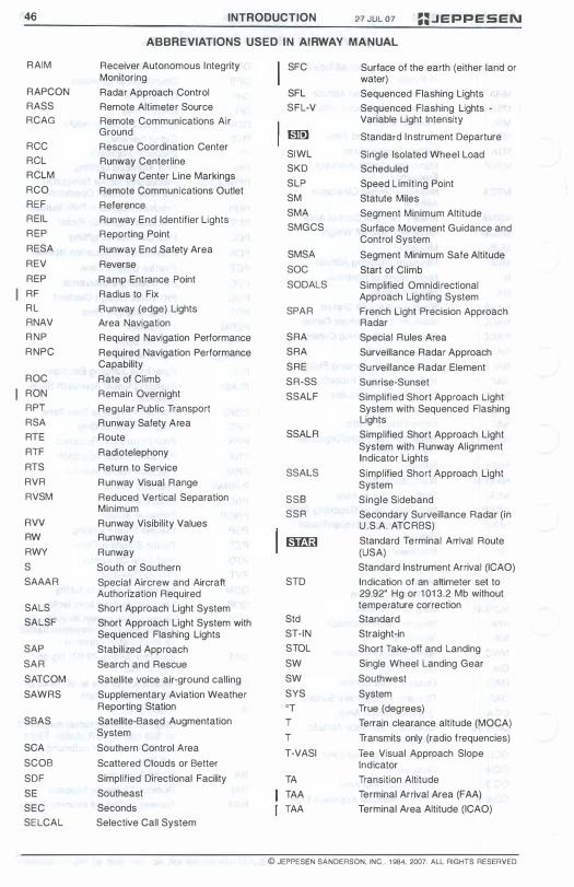
46
RAIM
RAPCON RASS RCAG
RCC RCL RCLM RCO REF REIL REP RESA REV REP RF RL RNAV RNP RNPC
ROC RON RPT RSA RT E RTF RT S RVR RVSM
RVV RW RWY S SAAAR
SALS SALSF
SAP SAR SAT COM SAWRS
SBAS
SCA SCOB SDF SE SEC SELCAL
INTRODUCTION 27 JUL 07 ::.JEPPESEN ABBREVIATIONS USED IN AIRWAY MANUAL
Receiver Autonomous Integrity SFC Surface of the earth (either land or Monitoring water) Radar Approach Control SFL Sequenced Flashing Lights Remote Altimeter Source SFL-V Sequenced Flashing Lights -Remote Communications Air Variable Light Intensity Ground lID!] Standard Instrument Departure Rescue Coordination Center SIWL Single Isolated Wheel Load Runway Centerline SKD Scheduled Runway Center Line Markings SLP Speed Limiting Point Remote Communications Outlet SM Statute Miles Reference SMA Segment Minimum Altitude Runway End Identifier Lights SMGCS Surface Movement Guidance and Reporting Point Control System Runway End Safety Area SMSA Segment Minimum Safe Altitude Reverse SOC Start of Climb Ramp Entrance Point SODALS Simplified Omnidirectional Radius to Fix Approach Lighting System Runway (edge) Lights SPAR French Light Precision Approach Area Navigation Radar Required Navigation Performance SRA Special Rules Area Required Navigation Performance SRA Surveillance Radar Approach Capability SRE Surveillance Radar Element Rate of Climb SR-SS Sunrise-Sunset Remain Overnight SSALF Simplified Short Approach Light Regular Public Transport System with Sequenced Flashing Runway Safety Area Lights Route SSALR Simplified Short Approach Light Radiotelephony System with Runway Alignment
Indicator Lights Return to Service SSALS Simplified Short Approach Light Runway Visual Range System Reduced Vertical Separation SSB Single Sideband Minimum SSR Secondary Surveillance Radar (in Runway Visibility Values U.S.A. AT CRBS) Runway � Standard Terminal Arrival Route Runway (USA) South or Southern Standard Instrument Arrival (ICAO) Special Aircrew and Aircraft ST D Indication of an altimeter set to Authorization Required 29.92" Hg or 101 3.2 Mb without Short Approach Light System temperature correction Short Approach Light System with Std Standard Sequenced Flashing Lights ST -IN Straight-in Stabilized Approach STOL Short Take-off and Landing Search and Rescue SW Single Wheel Landing Gear Satellite voice air-ground calling SW Southwest Supplementary Aviation Weather SYS System Reporting Station 'T True (degrees) Satellite-Based Augmentation T Terrain clearance altitude (MOCA) System T Transmits only (radio frequencies) Southern Control Area T -VASI Tee Visual Approach Slope Scattered Clouds or Better Indicator Simplified Directional Facility TA Transition Altitude Southeast TAA Terminal Arrival Area (FAA) Seconds TAA Terminal Area Altitude (ICAO) Selective Call System
© JEPPESEN SANDERSON. INC . . , 9B4. 2007. ALL RIGHTS RESERVED.
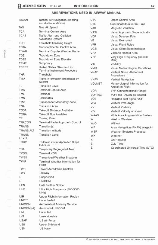
w w o ,
'" "
::JEPPESEN 27 JUL 07 INTRODUCTION 47
ABBREVIATIONS USED IN AIRWAY MANUAL
TACAN Tactical Air Navigation (bearing UTA Upper Control Area and distance station) UTC Coordinated Universal Time
TAS True Air Speed VAR Magnetic Variation TCA Terminal Control Area VASI Visual Approach Slope Indicator TCAS Traffic Alert and Collision VDP Visual Descent Point
Avoidance System VE Visual Exempted TCH Threshold Crossing Height VFR Visual Flight Rules TCTA Transcontinental Control Area VGSI Visual Glide Slope Indicator TDWR Terminal Doppler Weather Radar VHA Volcanic Hazard Area TDZ Touchdown Zone VHF Very High Frequency (30-300 TDZE Touchdown Zone Elevation MHz) TEMP Temporary VIS Visibility TERPS United States Standard for VMC Visual Meteorological Conditions
Terminal Instrument Procedure VNAP Vertical Noise Abatement THR Threshold Procedures TIBA Traffic Information Broadcast by VNAV Vertical Navigation
Aircraft VOLMET Meteorological Information for TL Transition Level Aircraft in Flight TMA Terminal Control Area VOR VHF Omnidirectional Range TML Terminal VORTAC VOR and TACAN co-located TMN Terminates VOT Radiated Test Signal VOR TMZ Transponder Mandatory Zone VPA Vertical Path Angle TNA Transition Area VV Vertical Visibility TODA Take-off Distance Available V/V Vertical Velocity or speed TORA Take-off Run Available WAAS Wide Area Augmentation System TP Turning Point W West or Western TRACON Terminal Radar Approach Control W/O Without TRANS Transition(s) WP Area Navigation (RNAV) Waypoint TRANS ALT Transition Altitude WSP Weather Systems Processor TRANS Transition Level WX Weather LEVEL X On Request TRCV Tri-Color Visual Approach Slope Z Zulu Time Indicator TSA Temporary Segregated Area Z Coordinated Universal Time (UTC)
TVOR Terminal VOR TWEB Transcribed Weather Broadcast TWIP Terminal Weather Information for
Pilots TWR Tower (Aerodrome Control) TWY Taxiway U Unspecified U UNICOM UFN Until Further Notice UHF Ultra High Frequency (300-3000
MHz) U IR Upper Flight Information Region UNCT'L Uncontrolled UNICOM Aeronautical Advisory Service UNICOM (A) Automated UNICOM UNL Unlimited UIS Unserviceable USAF US Air Force USB Upper Sideband USN US Navy
© JEPPESEN SANDERSON, INC., 1984, 2007. ALL RIGHTS RESERVED.

INTENTIONALL Y
LEFT
BLANK
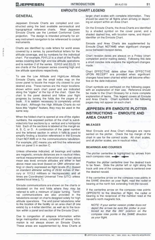
D.JEPPESEN I NTRODUCTION 29 AUG 03 51 EN ROUTE CHART LEGEND
GENERAL
Jeppesen Enroute Charts are compiled and constructed using the best available aeronautical and topographical reference charts. Most Jeppesen Enroute Charts use the lambert Conformal Conic projection. The design is intended primarily for airway instrument navigation to be referenced to cockpit instruments.
Charts are identified by code letters for world areas covered by a series, by parenthetical letters for the altitude coverage, and by numbers for the individual chart. For example, P(H/l)2 is a chart of the Pacific series covering both high and low altitude operations and is number 2 of the series. E(HI)3 and E(lO) 1 0 are charts of the European series covering high and low altitude operations respectively.
To use the low Altitude and High/low Altitude Enroute Charts, use the small index map on the cover panel to locate the major city closest to your desired area. These names are the major locations shown within each chart panel and are indicated along the "zigdex" at the top of the chart. Open the chart to the panel desired and follow your flight progress by turning the folds like the pages of a book. It is seldom necessary to completely unfold the chart. Although the High Altitude Charts do not have this "zigdex" feature, they may be used in the same way.
When the folded chart is opened at one of the zigdex numbers, the exposed portion of the chart is subdivided into four sections by a vertical and a horizontal fold. Each of the sections is labeled at the margin as A, B, C, or D. A combination of the panel number and the lettered section in which it falls is used to simplify finding a location referenced in the Enroute Chart NOTAMS or in the communications tabulation. For example, p5C means you will find the referenced item on panel 5 in section C.
Unless otherwise indicated, all bearings and radials are magnetic; enroute distances are in nautical miles; vertical measurements of elevation are in feet above mean sea level; enroute altitudes are either in feet above mean sea level (based on QNH altimeter setting) or clearly expressed as flight levels (Fl) (based on standard altimeter setting of 29.92 inches of Mercury or 1 01 3.2 mil libars or Hectopascals); and all times are Coordinated Universal Time (UTC) unless labeled local time (IT).
Enroute communications are shown on the charts or tabulated on the end folds where they may be referred to with a minimum of paper turning. Terminal communications are also provided in the tabulations except on charts designed solely for high altitude operations. The end panel tabulations refer to the location of the facility on an area chart (if one exists) by a 4-letter identifier, as well as to the location within a panel and section of the Enroute Chart.
Due to congestion of airspace information within large metropolitan areas, complete off airway information is not always shown on Enroute Charts. These areas are supplemented by Area Charts at
larger chart scales with complete information . They should be used for all flights when arriving or departing an airport within an Area Chart.
On the Enroute Charts, the Area Charts are identified by a shaded symbol on the cover panel, and a shaded dashed line, with location name, and Airport identifier on the Enroute Chart.
Enroute and Area Charts are supplemented by Enroute Chart NOTAMS when significant changes occur between revision dates.
Chart revision dates are always on a Friday (chart completion and/or mailing dates). Following this date a short concise note explains the significant changes made.
Chart EFFECTIVE dates other than EFFECTIVE UPON RECEIPT are provided when significant changes have been charted which will become effective on the date indicated.
Chart symbols are portrayed on the following pages with an explanation of their use. Reference should be made to the Chart Glossary for a more complete explanation of terms. This legend covers all Enroute and Area Charts. Chart symbols on the following pages may not appear on each chart.
JEPPESEN IFR EN ROUTE PLOTTER
INSTRUCTIONS - ENROUTE AND
AREA CHARTS
MILEAGES
Most Enroute and Area Chart mileages are represented on the plotter. Check the top margin of the chart in use for the correct scale. All chart scales, and all plotter scales, are in nautical miles.
BEARINGS AND COURSES
The plotter centerline is highlighted by arrows from each compass rose. � � Position the plotter centerline over the desired track to be flown. Slide the plotter left or right along the track until one of the compass roses is centered over the desired navaid.
If the centerline arrow on the compass rose points in the SAME direction as your flight, read the radial or bearing at the north tick extending from the navaid.
If the centerline arrow on the compass rose points OPPOSITE to the direction of flight, the radial or bearing is the reCiprocal of the number read at the navaid's north magnetic tick.
NOTE: If your earlier version plotter does not depict the arrows be sure the plotter is positioned so that the 360· position on the compass rose points in the SAME direction as your flight.
o JEPPESEN SANDERSON. INC .. 1 984, 2003. Al l.. RIGHTS RESERveo.
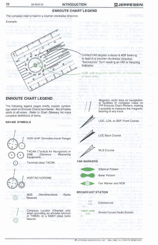
52 29 AUG 03 INTRODUCTION ==.JE��ESEN E N RO UTE C HA RT LEGEND
The compass rose is read in a counter-clockwise direction.
Example:
ENROUTE CHART LEGEND
The following legend pages briefly explain symbology used on Enroute Charts worldwide. Not all items apply in all areas. Refer to Chart Glossary for more complete definitions of items.
NAVAID SYMBOLS
I
VOR (VHF Omnidirectional Range)
TACAN (Tactical Air Navigation) or DME (Distance Measuring Equipment) Terminal class TACAN
VORTAC/vORDME
NOB (Nondirectional Beacon)
Radio
Compass Locator (Charted only when providing an enroute function or TWEB); or a SABH class radio beacon.
I�D8, with iVlagnetic North t ick, o n the enroute or alea chan.
I I / / /
FAN MARKERS
• • • �:,:�::.
Magnetic north ticks on navigational facilities fit compass roses on I FR Enroute Chart Plotters, making it possible to measure the magnetic bearing of any track.
LOC, LOA, or SDF Front Course
LOC Back Course
MLS Course
Elliptical Pattern
Bone Pattern
Fan Marker and NOB
BROADCAST STATION
(;) ZXN i340
TRINITV AFRS 1490
o
Commercial
Armed Forces Radio Station
@ JEPPESEN SANDERSON. JNC . . 1984, 2003. AL.L FliGHTS FlESEAVED.
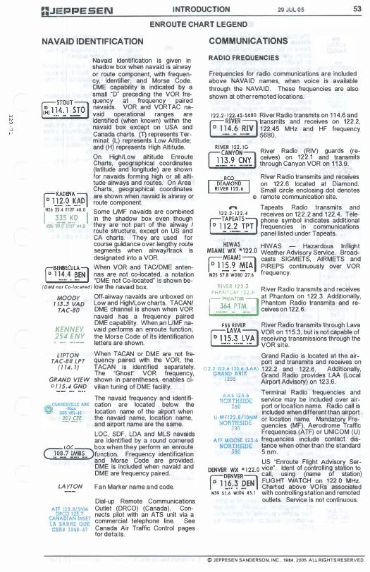
I NTRODUCTION 29 JUL 05 53
NAVAID IDENTIFICATION
ENROUTE CHART LEGEND
COMMUNICATIONS
�KADENA � I D 1].�·9_ ��D I N26 ZH EI27 46.0
I ��� -�!' I Nl6 '10.0 U71 H.B
Navaid identification is given in shadow box when navaid is airway or route component, with frequency, identifier, and Morse Code. DME capability is indicated by a small '0" preceding the VOR frequency at frequency paired navaids. VOR and VORTAC navaid operational ranges are identified (when known) within the navaid box except on USA and Canada charts. (T) represents Terminal; (L) represents Low Altitude; and (H) represents High Altitude. On High/Low altitude Enroute Charts, geographical coordinates (latitude and longitude) are shown For navaids forming high or all altitude airways and routes. On Area Charts, geographical coordinates are shown when navaid is airway or route component. Some UMF navaids are combined in the shadow box even though they are not part of the airway / route structure, except on US and CA charts. They are used for course guidance over lengthy route segments when airwayltrack is designated into a VOR.
fBENBECULANl When VOR and TAC/DME anten� 1 1 4.4 BE, \ nas are not co-Iocat:�, a notation
_ _ ••• . _. _ 'DME not Co-located IS shown belOME nOI Co·local.d) low the navaid box. MOODY Off-airway navaids are unboxed on
1 13.3 VAD Low and High/Low charts. TACAN/ TAC-SO DME channel is shown when VOR
navaid has a frequency paired DME capability. When an UMF na
KENNEY vaid performs an enroute function, 254 ENY the Morse Code of its identification •
_. -.-- letters are shown. LIPTON
TAC·SS LPT ( 1 14. 1)
GRAND VIEW 0 / 15.4 GND
When TACAN or DME are not frequency paired with the VOR, the TACAN is identified separatety. The 'Ghost" VOR frequency, shown in parentheses, enables civilian tuning of DME facility. The navaid frequency and identifIcation are located below the location name of the airport when the navaid name, location name, and airport name are the same. LOC, SDF, LOA and MLS navaids are identified by a round cornered
LOC box when they perform an enroute Gl l§iDfunction. Frequency identifi�tion
and Morse Code are provided. DME is included when navaid and DME are frequency paired.
LAYTON
ATf 122.S/SNM DR CO 125.7
CANADIAN INSET LA SARRE QUE CSR8 1 048-4'
Fan Marker name and code.
Dial-up Remote Communications Oullet (DR CO) (Canada). Connects pilot with an ATS unit via a commercial telephone line. See Canada Air Traffic Control pages for details.
RADIO FREQUENCIES
Frequencies for radio communications are included above NAVAID names, when voice is available through the NAVAID. These frequencies are also shown at other remoted locations.
122.2 - 122.45-5680 River Radio transmits on 1 14.6 and hRIVERWl transmits and receives on 122.2,
D 1 1 4.6 RIV 1 22.45 MHz and HF frequency .-. .. ... - 5680. RI'te:NVSilIG River Radio (RIV) guards (re-
S13 9 CNYl ceives) on 122.1 and transmits '---l._. '-. -fgJ through Canyon VOR on 1 1 3.9. River Radio transmits and receives on 122.6 located at Diamond. Small circle enclosing dot denotes
<1> remote communication site. .., Tapeats Radio transmits and
122.2-122.4 receives on 122.2 and 1 22.4. Tele-�TAPEATS ::::l phone symbol indicates additional I D 1 1 2.2 T�T I frequencies in communications
- • __ • - panel listed under Tapeats. HIWAS HIWAS - Hazardous Inflight MIAMI WX *122.0 Weather AdviSOry Service. Broad� MIAMI :::1 casts SIGMETS, AIRMETS and I D l l�·�. �IA I PI REPS continuously over VOR
N25 57.S woao 21.6 frequency.
RIVER 122.3 River Radio transmits and receives f'HAtJTO'.'. 1 22 .6 Ph t 1 22 3 Add't' I I PHANTOM
J
at an om on . . I lona y, r364 PTM Ph.antom Radio transmits and re-L:;_. - -- celves on 122.6. FSS RIVER River Radio transmits through Lava FULAVA� VOR on 1 1 5.3, but is not capable of
1>11 5.3 � receiving transmissions through the ----= .. ... --=-. VOR site. Grand Radio is located at the airport and transmits and receives on
122.2 1 2 2 . 6 1 23.6 ( lAA) 1 22.2 and 1 22.6. Additionally, GRAND ARIZ Grand Radio provides LAA (Local 1285 Airport Advisory) on 123.6. AAS 123.6 Terminal Radio frequencies and
NORTHSIDE service may be included over air-390 port or location name. Radio call is included when different than airport
U-MFI22.8/l0NM or location name. Mandatory Fre-NORTHSIDE quencies (MF), Aerodrome Traffic 390 Frequencies (ATF) or UNICOM (U) ATF MOOSE 123.6 frequencies include contact dis-
NORTHSIDE tance when other than the standard 390 5 nm. US "Enroute Flight Advisory Ser
DENVER WX * 1 22.0 vice". Ident of controlling statiof'! to DENVER call, usmg (name of station) F1 L�;� p.ENl ��I��� ����H
vg�s1�2
s�0�a7:d N39 51.6 Wl04 45.1 with controlling station and remoted
outlets. Service is not continuous.
� JEPPESEN SANDERSON. INC . . 1984. 2005. ALL RIGHTS RESERVEO.

54 29 JUL 05 INTRODUCTION ==.JEPPESEN ENROUTE CHART LEGEND
'" VIRAC RADIO
SECTOR 2 -N;ANilAl cmnROl I ;��:� ��6: � I
BELGRADE
@6�40)
SOUTH EASTERN RADIO
2869 .4678 5526 8876
RADIO NASSAU
E CAR 1 24.2
5566 6537 8871 13344
CHICAGO'! -.- .. g!.:� ..... j
The telephone symbol indicates additional communications may be found in the communications tabulation after the associated NAVAID or location name. Telephone symbol does not necessarily mean that voice is available through the NAVAID. Call and frequencies of Control Service for use within graphically portrayed Radio Frequency Sector Boundaries. Call sign "CONTROL" and I or "RADAR" is omitted in all communication boxes in several regions.
Plain language infllght weather station with name and frequency.
Call and frequencies of control or unit service. For use within geographical defined radio boundaries.
Call and frequency of enroute service or control unit. SINGLE SIDE BAND capabilities are available unless specified otherwise.
Remote air-Io-ground antenna for direct communications with control center. Center is named in large type and name of remote site is in parentheses below followed by appropriate VHF frequencies.
NAVAID/COMMUNICATION DATA
Operational status at date of publi(May be Shutdown) cation. Refer to Chart NOTAMS for (May be Test Only) current status, including substitute
b C d) routes for VOR and VORTAC (May not e omsn shutdowns. (TWEB)
MA YBE 326 MBY
(WX) EAST BAY J62 EZB
(TWEB) indicates continuous automatic weather broadcast IS
provided on the facility frequency.
Class SABH radio beacons of limited navigation suitability indicate their primary purpose of continuous automatic weather broadcast by (WX).
(R)
*
Enroute Radar capability. (All domestic U.S. Centers are radar equipped so (R) is omitted from domestic U.S. Center boxes.) Underline shown below navaid identifier indicates Beat Frequency Oscillator (BFO) required to hear Morse Code identifier. Asterisk indicates navaid operation or service not continuous. Marine beacon operation times. Transmission begins at 4 minutes past the hour and every 1 5 minutes
H • 04 & 15(1) thereafter in this illustration; other times will be indicated. Number in parentheses gives duration in minutes of transmission. Facility operates in fog only at
FOG:H • 02 & 08 times indicated.
RESTRICTED AIRSPACE
(Not shown on Eastern Hemisphere chart series when vertical l imits are below 2000 feet AGL)
o D
Restricted airspace. The accompanying label indicates it as prohibited, restricted , danger, etc.
Training, Alert, Caution, and Military Operations Areas.
Country identifier, des ignation _______ in parens, and number CY(R)-4207 ___ Upper Limit � L" � _ Lower Imlt
SS-SA --- Hours active (MSP ARTCC) ___
· ED (R)-7
R·600 1 1 2=0 1 (JAX ARTee)
---- Controlling Agency (Limits may be tabulated)
Dot indicates permanent activation on some chart series.
On USA charts K (indicating USA) and parens around the designating letter are omitted.
When restricted airspace areas overlap, a line is shown on the outer edge of each area through the area of overlap.
© JEPPESEN SANDERSON, INC" 1984, 2005. ALL RIGHTS RESERVED.
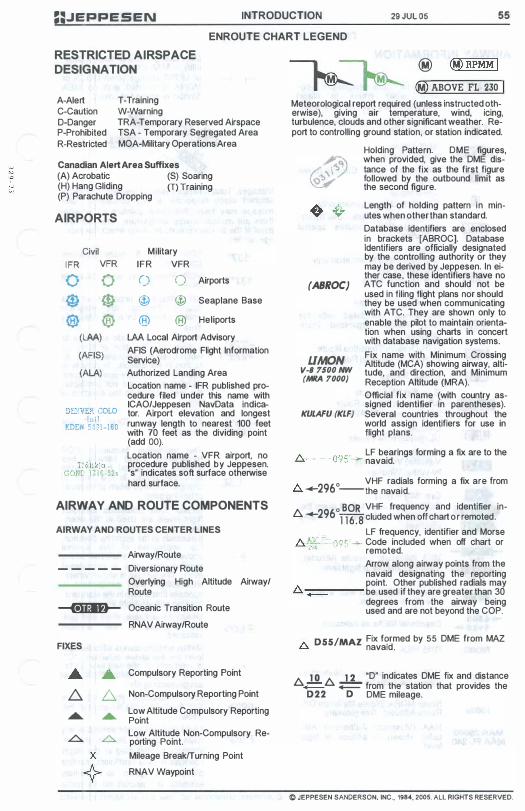
==.JEPPESEN INTRODUCTION 29 JUL 05 55 ENROUTE CHART LEGEND
RESTRICTED AIRSPACE
DESIGNATION
A-Alert C-Caution D-Danger P-Prohibited R-Restricted
T-Training W-Warning TRA-Temporary Reserved Airspace TSA - Temporary Segregated Area MOA-Military Operations Area
Canadian Alert Area Suffixes (A) Acrobatic (S) Soaring (H) Hang Gliding (T) Training (P) Parachute Dropping
AIRPORTS
Civil I FR VFR
o 0 @ <!> ® ®
(lAA) (AFIS)
(ALA)
DENV ER COLO -Irdl
KDEN 5431-160
Military IFR VFR
o 0 Airports
@ @ Seaplane Base
® ® Heliports
lAA Local Airport Advisory AFIS (Aerodrome Flight Information Service) Authorized Landing Area Location name - IFR published procedure filed under this name with ICAO/Jeppesen NavData indicator. Airport elevation and longest runway length to nearest 100 feet with 70 feet as the dividing point (add 00). Location name - VFR airport, no
Tldjikja procedure published by Jeppesen. GONu 1 3 1 6-52s "s" indicates soft surface otherwise
hard surface.
AIRWAY AND ROUTE COMPONENTS
AIRWAY AND ROUTES CENTER LINES
Airway/Route - - - - - Diversionary Route
Overlying High Altitude Airway/ Route
---I!DIIfJ-- Oceanic Transition Route RNAV Airway/Route
FIXES
... ... Compulsory Reporting Point
.6.. .6.. Non-Compulsory Reporting Point
...... ...... Low Altitude Compulsory Reporting Point
A A Low Altitude Non-Compulsory Re-porting Point.
X Mileage BreaklTurning Point
<} RNAV Waypoint
@ (M)RPMMI eM) ABOVE FL 230 I
Meteorological report required (unless instructed otherwise), giving air temperature, wind, icing, turbulence, clouds and other significant weather. Report to controlling ground station, or station indicated.
(ABROC)
LIMON V-I 7500 NW (MRA 7000)
KULAFU (KLF)
Holding Pattern. DME figures, when provided, give the DME distance of the fix as the first figure followed by the outbound limit as the second figure.
Length of holding pattern in minutes when other than standard. Database identifiers are enclosed in brackets [ABROC]. Database Identifiers are officially designated by the controlling authority or they may be derived by Jeppesen. In either case, these identifiers have no ATC function and should not be used in filing flight plans nor should they be used when communicating with A TC. They are shown only to enable the pilot to maintain orientation when using charts in concert with database navigation systems. Fix name with Minimum Crossing Altitude (MCA) showing airway, altitude, and direction, and Minimum Reception Altitude (MRA). Official fix name (with country assigned identifier in parentheses). Several countries throughout the world assign identifiers for use in flight plans.
A , LF bearings forming a fix are to the �095 -+- navaid.
A 2960 VHF radials forming a fix are from L..>. � --the navaid.
1::.. 2960 BOR VHF frequency and identifier in-� 1 1 6 .8 cluded when off chart o r remoted.
.. LF frequency, identifier and Morse £:"J.ar; �" :1') 5· ....... Code included when off chart or li4 . . remoted.
Arrow along airway points from the navaid designating the reporting point. Other published radials may be used if they are greater than 30 degrees from the airway being used and are not beyond the COP.
A D55/MAZ Fix f<;>rmed by 55 DME from MAZ L..>. navald .
1 0 1 2 "D" indicates DME fix and distance 1::.. ,- 1::.. =- from the station that provides the D22 D DME mileage.
<C> JEPPESEN SANDERSON, INC., 1984, 2005. ALL RIGHTS RESERVED.
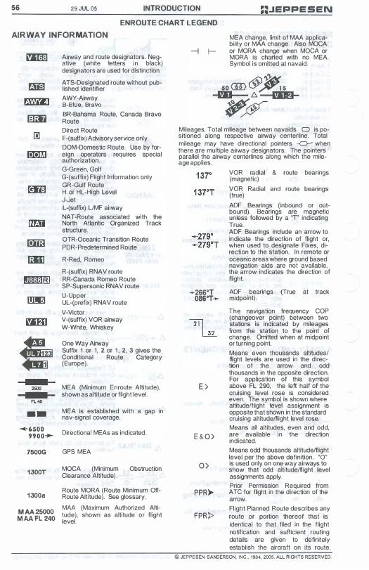
56 29 JUL 05 INTRODUCTION ::.JEPPESEN ENROUTE CHART LEGEND
AIRWAY INFORMATION
2500
FL�
_ . �6500
9900+-7500G
1300T
1300a
Airway and route designators. Negative (white letters in black) designators are used for distinction. A TS-Designated route without published identifier AWY-Airway B-Blue, Bravo BR-Bahama Route, Canada Bravo Route Direct Route F-(suffix) Advisory service only DOM-Domestic Route. Use by foreign operators requires special authorization, G-Green, Golf G-(suffix) Flight Information only GR-Gulf Route H or HL-High Level J-Jet L-(suffix) LlMF airway NAT-Route associated with the North Atlantic Organized Track structure. OTR-Oceanic Transition Route PDR-Predetermined Route R-Red, Romeo R-(suffix) RNAV route RR-Canada Romeo Route SP-Supersonic RNAV route U-Upper UL-(prefix) RNAV route V-Victor V-(suffix) VOR airway W-White, Whiskey
One Way Airway Suffix 1 or 1, 2 or 1 , 2, 3 gives the Conditional Route Category (Europe).
MEA (Minimum Enroute Altitude), shown as altitude or flight level.
MEA is established with a gap in nav-signal coverage.
Directional MEAs as indicated ,
GPS MEA
MOCA (Minimum Obstruction Clearance Altitude) .
Route MORA (Route Minimum OffRoute Altitude). See glossary, MM (Maximum Authorized Alti:::: ��� tude), shown as altitude or flight level.
I-MEA change, limit of MM applicabil�y or MAA change. Also MOCA or MORA change when MOCA or MORA is charted with no MEA, Symbol is omitted at navaid.
Mileages, Total mileage between navaids C) is positioned along respective airway centerline. Total mileage may have directional pointers � when there are multiple airway designators, The pointers parallel the airway centerlines along which the mileage applies.
VOR radial & route bearings (magnetic) VOR Radial and route bearings (true) ADF Bearings (inbound or outbound). Bearings are magnetic unless followed by a 'T' indicating True. ADF Bearings include an arrow to indicate the direction of flight or, when used to designate Fixes, direction to the station. In remote or oceanic areas where ground based navigation aids are not available, the arrow indicates the direction of flight.
_266°T ADF bearings (True at track 086°T- midpoint).
21l ill
E >
E & O )
0)
PPR>-
FPRP
The navigation frequency COP (changeover point) between two stations is indicated by mileages from the station to the point of change. Omitted when at midpoint or turning point. Means even thousands altitudes/ flight levels are used in the direction of the arrow and odd thousands in the opposite direction. For application of this symbol above FL 290, the left half of the cruising level rose is considered even. The symbol is shown where altitude/flight level assignment is opposite that shown in the standard cruising altitude/flight level rose. Means all altitudes, even and odd, are available in the direction indicated, Means odd thousands altitude/flight level per the above definition. "0" is used only on one way airways to show that odd altitude/fl ight level assignments apply. Prior Permission Required from ATC for flight in the direction of the arrow. Flight Planned Route describes any route or portion thereof that is identical to that filed in the flight notification and sufficient routing details are given to definitely establish the aircraft on its route,
© JEPPESEN SANDERSON, INC., 1984, 2005. ALL RIGHTS RESERVED.

;;.JEPPE SEN I NTRODUCTION 29 JUl 05 57 ENROUTE CHART LEGEND LOW & HIGH/LOW ALTITUDE CHART LEGEND
�Al AREA Class "A" a rspace upper limit Fl 300 , W16 .. Grid lat-long values �
Shadow box when navaid is airway component, with frequency, identif ier , Morse Code and INS coordinates, Small "0" Indicates OME. Class Indicated by: (T)-Terminal, (l) low, (H) High. N 0
' location name-IFR airport in blue, publ ished procedure f l ied under this with ICAO/Jeppesen NavOata indicator. a i rport elevat ion and longest r length to neareot 1 00 feet with 70 feet as the dividing point (add 00). I (VFR a irpor ts ate Shown In green) <.-k!'.'i.''f'J'�:;'" Area chart coverege
+-Magnetic Var iation \
Non-compulsory (eport Ing point
"0" Indlcatu OME f i x . Segment mileage .-(' -:. IS)OME distance fr;m navald .
OO� l( o� OMAS _ Offlclall � named Grid MORA (Values less than 14 ,000 feet are green) )
High A l t i tude Routa included for orientat i on onl y Arrow from fac i l i ty designating reporting point �� Compulsory reporting point � ���
h C�
aO��i���es ---""
Intersection or f ix formation (Bearing, frequency and ident of remote VHF navaid; Morse code shown when navaid is outside of chart neat l ine)
l:i L intersection MCA FL 60 SE Minimum Crossing � '- Alti tude (MCA) \ 'MEA for SE-bound f l ights
change y Segment mileage
� yChangeover Point
� Special use airspace
"0" with distance indicates total OME distance from navaid.
r,:;-;NAME I 1.! 2.:�. ��_S CABO) N26 20.0 W014 05.0 N26 08.3 M' . R t l W014 38 6 ""-- , "Imum ecep on
MRA 7000 Alt i tude (MRA) OME or
Holding pattern T ACAN Total mileage 0 NAME
Uncontro l led @) ........ between navalds DME-79 A8 airspace .,. ;c ( 1 13.2)
®
(Class G) :.t> Airway DeSignator � / /" F l ight p lanning relevant restrictions for
-:; ATS routes on Eastern Hemisphere �oute usabi l i ty by non � • chart series are published on respective
)( B-RNAV equipped aircraft '" ENROUTE pages :":; .
(within Europe only) 'f, /... Maximum Author i zed Altitude / "?>. .-� .K (MAA) Min imum Obstruction ��'f" / RNAV ATS route o '"
Unnamed, official � published ATS route with d irection indication
Clearance A l t i tude (MOCA) / . (outSide Europe) :Po .....-Condil ional Route Category � ¥ (See Enroute list ing )
FIR/UIR Boundary Change to adjoining Aerodrome flight name, ident i f ier and enroute chart . information serv ice. ai rspace category � )1. Aster isk indicates PTO. -\ .. �",I \. location name-VFR airport
""" In green, no procedure CANARIES GCCC published by Jeppesen (lFR FIRCG)/UlRCG) airports are shown in blue) ,
D Direct Route ), " .. I dl I II AKAR GOOO FIR CG):/UI C (Requires ATC approval, wi l l i.r. J • n co e� so sur-R G) not be accepted in F l ighl Plan) � Ieee otherWIse hard
� � surface . . . X .. 32 NOB C,v,l or Joint r£ABROCI . 2650,,\1 . Civi l/Mi l itary
Route Minimum Off-Route -2600a -�: . . .• �. Airport A l t i tude (Route MORA) Met report . ' ry64 "\'\ required ...... " __ -.
Database identif iers are enclosed In brackets [ABROC}. Database -..4l;'" UG 8 - 1\ identifiers are officially designated by the controlling state authority .)� -, 0 (*AFIS) \ or they may be derived by Jeppesen. In either case, these identifiers . .; Tidjikjc .�. have no ATC function and should not be used in filing flight plans nor 13 AfAR Rl GQND 1 3 1 6-52 y; .;. should they be used when communicating with A TC. They are shown 326 .".R '�J81 TKA " .?",, ' only to enable the pilot to maintain orientation when using charts in .- v.�" - -.=--:::- ;f concert with database navigation systems. N20 ::'0.0 WOl3 Q4.0 NDB with deSignator &
Morse code (Off-Route)
© JEPPESEN SANDERSON, INC .. 1999, 2005. ALL RIGHTS RESERVED.
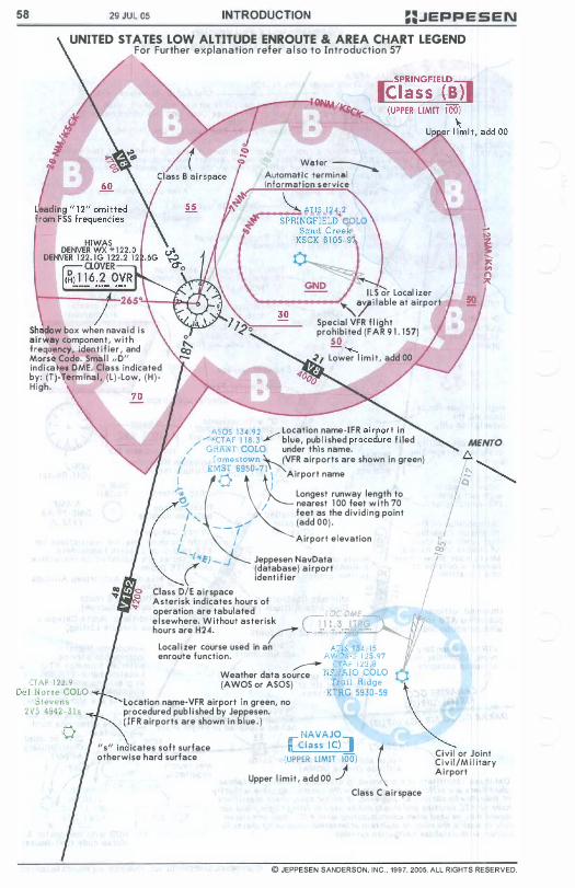
58 29 JUl 05 INTRODUCTION ��JEPPESEN
UNITED STATES LOW ALTITUDE ENROUTE & AREA CHART LEGEND For Further explanation refer a l so to Introduction 57
Sh�w box when navaid i s air�ay component, wi t h freq�ency, iden t i fier I and Morse Code. Sma l l "0" indica! l OME. Class Indicated by: (T)- ermina l , (L) -Low, ( H ) High.
W8'er � AutomaUc terminal Information service
___ �"",,;:::' AlI� 114.2 SPRINGFIELD· COLO
I L S or Local izer "'7Hable at airport
Special VFR f l ight prohibi ted (FAR 9 1 . 157)
50 -......... <I Lower l imit , add 00
�OO�
ASOS 1 34.92 Location name-IFR airport in / '::.'CTAF 1 1 8 .3 / blue, pub l i shed procedure f i led MENTO / liRHNT COLO under thiS name. I I amestown NVFR airports are shown in green) ( r;dK�5 69x:50_7�I ) Airport name
� Longest runway length to � / nearest 1 00 feet w i th 70 (r " feet as the dividing point , '- _/ (add 00). - - I , / Airport elevation I"
(TAF 1 22 .9
'- -r'fE) _ ..J Jeppesen NavData ( (database) ai rport ident i f ier
Class D/E airspace Asterisk indicates hours of operation are tabulated ' L:.DMf el sewhere. Without asterisk (11 1 .3 IT hours are H24. / '-. -- � . .:- =-Local i zer course used in an AllS I 4 15
enroute function. AV.J.)5 ,: 1 15 97 � (TAt: J :.! .! 8 Weather data source "Po J AJO COLO
l
uei Norte COLO Stevens
(AWaS or ASOS) 1,,"11 Ridge KTRG 5930-59
Location name-VFR airport in green, no procedured pub l i shed by Jeppesen. 2V5 4942-3 1 5 ( I F R airports are shown in blue . )
ff sIt in icates soft surface otherwise hard surface
_ NAVAJO I Class (el] (UPPER LIMIT 100)
Upper l imit, add 00 j ( Civi l or Joint
Civ i l/M i l itary Ai rport
Class C airspace
© JEPPESEN SANDERSON. INC., 1997, 2005. ALL RIGHTS RESERVED.
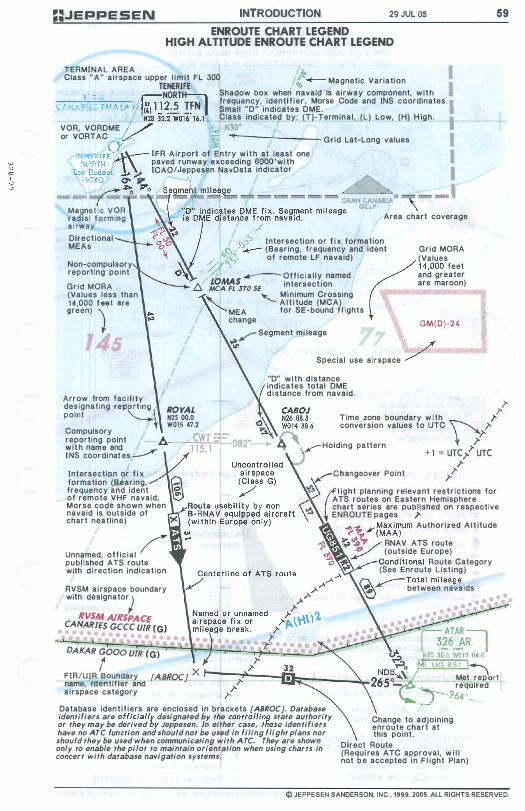
==JEPPESEN INTRODUCTION 29 JUL 05 ENROUTE CHART LEGEND HIGH ALTITUDE ENROUTE CHART LEGEND
TERMINAL AREA � Class "A" ai rspace upper l im i t FL 300 :.. __ Magnetic Variation TENERI FE � NORTH Shadow box when navaid is airway component, with
_ F '_C'�, , . , A�1 1 2 5 TFN I frequency, identi f ier , Morse Code and INS coordinates .• �AN.",Rli:S TMA\Afl liL) I� • Small "D" indicates DME. / N28 32,2'W016'16,l Class indicated by: (T)-Terminal , (L) Low, (H) H igh. VOR, VORDME l ./ .., N30' or VORTAC ,V ;; � Grid Lat-Long values cr �
TEM:R1FE"1\.· IFR Airport of Entry with at least one Nr'R'fF ' paved runway exceeding SOOO'with
Lc� Rod�o. -'"' ? ICAO/Jeppesen NavDa!a indicator GGXO 0'" V � � Po
- - , Magnet i c VOR radial forming ai rway Direct ional MEAs
Non-compulsory reporting point Grid MORA (Values less than 14,000 f •• t are green) )
Arrow from fac i l i ty designating reporting
Area chart coverage
�.$ Intersection or f i x formation � / :.-- (Bearing, frequency and iden! Grid MORA 0�� of remote LF navaid) (Values �\ // �" , (
14,000 feet ()� .� _Officia l ly named and greater t:{ £��S3'70 SE intersect IOn are maroon)
� '- Minimum Crossing A l t i tude (MCA)
MEA for SE-bound f l ights change GM(D) -24
,-Segment mi leage � /
Special use airspace / "D" with distance indicates total DME d istance from navaid.
59
point �\ ROYAL N2S 00,0 W01S 47.2 "
" Time zone boundary w i th " conversion values to UTC � Compulsory reporting point 6. __ �:!.!."""'_ f��
h C����i���es�
Intersection or f i x formation (Bearing, frequency and ident of remote VHF navaid; Morse code shown when navaid is outside of chart neatline)
Unnamed, official / publ ished ATS route with d i rection indication
RVSM ai rspace boundary with deSignator)
RVSM AIRSPACE CANARIES GCCC U/R (G) •
DAKAR GOOD U/R CG)
�Holding pattern � ,,): \ + 1 = UTC" UTC " ,-Changeover Point ;-
'? �li9ht planning relevant restr ict ions for ATS routes on Eastern Hemisphere
vi! chart series are publ ished on respective .. ENROUTE pages ,,'
,).,).
1-� .¥1tati")um Authorized A l t itude
';>\?, ./ RNAV ATS route / _ (outside Europe) 'III! . ___ Conditional Route Category "' .¥ (See Enroute List ing) ..A..A @>""""'-Total mi leage
,.>-.A � between navaids
l' ,,).�,",\Yl " r 7:
t FIR/UIR Boundary fABROe] X t---";!"�--fii:: ____ "'::� name, Identifier and
>.,," I UG 8 5 1 � Met report
"""- required ai rspace category ,
Database ident i f iers are enclosed in brackets [ABROC], Database identifiers are officially designated by the controlling state authority or they may be derived by Jeppesen. In either case, these identifiers have no ATC function and should not be used in filing flight plans nor should they be used when communicating with A TC. They are shown only to enable the pilot to maintain orientation when using charts in concert with database navigation systems.
,J -264 o __ �_
Change to adjoining enroute chart at this point ,
Direct Route (Requi res ATC approval, w i l l not be accepted in F l ight Plan)
© JEPPESEN SANDERSON, INC., 1999, 2005. ALL RIGHTS RESERVED.
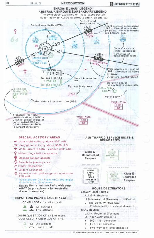
60 29 JUL 05 INTRODUCTION ==.JEPPESEN ENROUTE C HART LEGEND
A USTRALIA ENROUTE & AREA CHART LEGEND The symbology expla ined on these pages pertain
spec i f i ca l l y to Austra l i a Enroute and Area charts.
Control zone l imits (CTR)
ro JACKSON :;;, I D 1 12.9 CK I 527 27.3 E151 44.2 I t �?_� �.� I
� F l ight plannln9 requirement � ( FPR). Direction indicated
• ./ by arrow. For requirement, rJr:, ... ___ see Enroute Tab.
�b \t \ (C) LO!i:'? (C) FL200 Fl200 � �500 4000 � , Class C a i r space l imits (sectorized)
2o"�J:Mil��a9f route
Elevation and/or 527 27.3 E15 1 50.2 Fly neighborly area runway length unavai lable.
Bollon OLD J # 1 1 8 . 8 Maz Shaffer OLD YBfr 1 43-38 (1 [F!T-i]) YBLL�(1 �
Water body ' Mandatory broadcast zone (M8Z) YM R -35 1 A
FL200
Frequency for voice communication of M8Z or CTAF .(# symbol Indicates non-s tandard M8Z or CTAF dimension. Refe r t o A i rport Di rectory)
SPECIAL ACTIVITY AREAS
..". U l t r a - l ight act i v i ty above 500' AGL.
j3:I- Hang g l ider act i v i t y above 5000' AGL.
T Model a i rcraft act i v i t y above 300' AGL.
<;> Meteorology bal loon ascents.
+ Manned bal loon ascent s .
\' Parachute jumping a r e a .
.>r G l i d e r Operations.
j1Y Gliders Launching. fZI A i rport w i t h i n V H F range of respons i b l e
ATS un i t . ff Non-st andard CTAF and M B Z . s e e a i r po r t
d i rectory ior dimensions. Navaid I imitation, see Rad io Aids page
t t AU-37 (appl icable o n l y lor Austral ia domest i c services ) .
REPORTING POINTS ( AUSTRALIA)
COMPULSORY for a l l a i r c r a f t .
JJ. A A l l a l i t i tud e ...... ....... Low a l t i tude
ON-REQUEST 300 KT T A S or more. COMPULSORY Under 300 KT TAS .
.6 D. A l l a l t i tude � .L::::.. Low a l t i tude
YM R -3518 FL200 GNO
GND
AIR TRAFFIC SERVICE UNITS & BOUNDARIES
Class G Uncontrolled
Airspace
PERTH RADIO 1 1 8 . 1 INO- l
3476 5634 17061
Class E Controlled Airspace
ROUTE DESIGNATORS Convent ional Routes:
A , B , G , R : Reg ional H (one-w a y ) , J ( two-way ) : Domest i c
V (one-way) , W ( two-way ) : Predom i nan t l y l o w - l e v e l dome s t i c
RNAV Routes:
L , M , N : Regional (Tasman) Q : 1 80 ° - 359° domestic Y: 360 ° - 1 79° domes t i c T : Two-way dome s t i c
Z : Two-way low-level domes t i c
© JEPPESEN SANDERSON. INC .. 1996. 2005. ALL RIGHTS RESERVED.
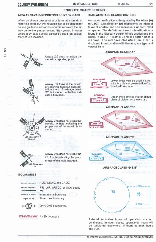
::JEPPESEN INTRODUCTION 29 JUl 05 61 ENROUTE CHART LEGEND
AIRWAY NAVAIO/REPORTING POINT BY-PASS
When an airway passes over or turns at a navaid or reporting point, but the navaid is not to be utilized for course guidance and/or no report is required, the airway centerline passes around the symbol. In cases where a by-pass symbol cannot be used, an explanatory note is included.
Airway J26 does not utilize the navaid or reporting point.
Airway J14 turns at the navaid or reporting point but does not utilize them. A mileage break "X" is included to further indicate a turn point.
Airway V76 does not utilize the navaid. A note indicaling Ihe proper use of the navaid is included.
��"'��. "'V1�l lnt. Airway V76 does not utilize the Int. A note indicating the proper use of the Int is included.
BOUNDARIES
...................
. ..................
QNH -0-0-0-0-0-QNE
ADIZ, DEWIZ and CADIZ
FIR, UIR, ARTCC or OCA boundary.
International boundary.
Time zone boundary.
QNH/QNE-boundaries.
RVSM AIRSPACE RVSM boundary
ICAO AIRSPACE CLASSIFICATIONS
Airspace classification is designated by the letters (A) thru (G). C lassification (A) represents the highest level of control and (G) represents uncontrolled airspace. The definition of each classification is found in the Glossary portion of this section and the E n route and A i r Traffic Control section of t h i s m a n u a l . T h e a i rs pa ce classif icat ion l e t t e r is displayed in association with the airspace type and vertical limits.
AIRSPACE CLASS "A"
STAVANGER UTA @au (AIJ (LOWER LIMIT!!!!!)
Lower limits may be used if it results in a clearer presentation (Le. "stacked" airspace.
L��N Upper limits omitted if at or above @au <Aj] plane of division on a low chart.
AIRSPACE CLASS "B"
AIRSPACE CLASS "C"
AIRSPACE CLASS "0 & E"
1.*'0\--- ..... , /' "
I ' ( " E ' '\ - - - r. 1 __ _ I \ I 1 30' \ 30 I
f I 1 5 : \ I ' \ I '
\ I - -���-� , / " �/ .......... _ _ _ 1..*'0
Asterisk indicates hours of operation are not continuous. In such cases, operational hours will be tabulated elsewhere. Without asterisk hours are H24.
© JEPPESEN SANDERSON. INC .• 1984, 2005. ALL RIGHTS RESERVED.
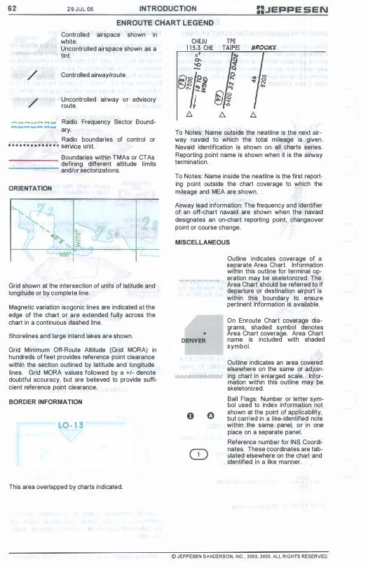
62 29 JUL OS INTRODUCTION ==JEPPE SEN EN ROUTE CHART LEGEND
/
/
Controlled airspace shown in white. Uncontrolled airspace shown as a tint.
Controlled airway/route.
Uncontrolled airway or advisory route.
---- .. .. - Radio Frequency Sector Bound-ary.
Radio boundaries of control or • • • • • • • • • • • • • • service unit.
_______ Boundaries within TMAs or CTAs ______ defining different altitude limits
and/or sectorizations.
ORIENTATION
Grid shown at the intersection of units of latitude and longitude or by complete line.
Magnetic variation isogonic lines are indicated at the edge of the chart or are extended fully across the chart in a continuous dashed line.
Shorelines and large inland lakes are shown.
Grid Minimum Off-Route Altitude (Grid MORA) in hundreds of feet provides reference point clearance within the section outlined by latitude and longitude lines. Grid MORA values followed by a +/- denote doubtful accuracy, but are believed to provide sufficient reference point clearance.
BORDER INFORMATION
LO- 1 3
This area overlapped by charts indicated.
CHEJU 1 1 5.3 CHE
To Notes: Name outside the neatline is the next airway navaid to which the total mileage is given . Navaid identification is shown on all charts series. Reporting point name is shown when it is the airway termination.
To Notes: Name inside the neatiine is the first reporting point outside the chart coverage to which the mileage and MEA are shown.
Airway lead information: The frequency and identifier of an off-chart navaid are shown when the navaid designates an on-chart reporting point, changeover point or course change.
MISCELLANEOUS
DENVER
o 0
Outline indicates coverage of a separate Area Chart. Information within this outline for terminal operation may be skeletonized. The Area Chart should be referred to if departure or destination airport is within this boundary to ensure pertinent information is available.
On Enroute Chart coverage diagrams, shaded symbol denotes Area Chart coverage. Area Chart name is included with shaded symbol.
Outline indicates an area covered elsewhere on the same or adjoining chart in enlarged scale. Information within this outline may be skeletonized.
Ball Flags: Number or letter symbol used to index information not shown at the point of applicability, but carried in a like-identified note within the same panel, or in one place on a separate panel.
Reference number for INS Coordinates. These coordinates are tabulated elsewhere on the chart and identified in a like manner.
© JEPPESEN SANDERSON. INC . . 2003. 2005. ALL RIGHTS RESERVED.
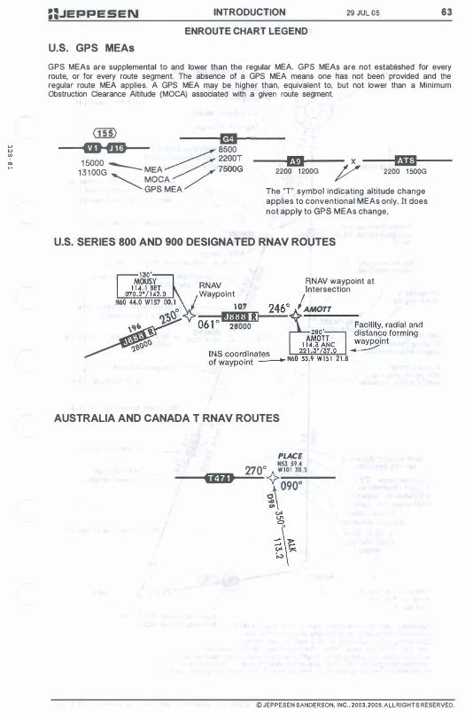
==.JEPPESEN INTRODUCTION 29 JUL 05 63 ENROUTE CHART LEGEND
u.s. GPS MEAs
GPS MEAs are supplemental to and lower than the regular MEA. GPS MEAs are not established for every route, or for every route segment. The absence of a GPS MEA means one has not been provided and the regular route MEA applies. A GPS MEA may be higher than, equivalent to, but not lower than a Minimum Obstruction Clearance Altitude (MaCA) associated with a given route segment.
G1ID _____ L-__ __ mJ-----m-a-- � 8500
1 5000 � /. 2200T m x
2200 1200G � rJD--2200 1500G 1 3 1 00G -- MEA / / 7500G � MOCA
GPS MEA The "T" symbol indicating altitude change applies to conventional MEAs only. It does not apply to GPS MEAs change.
u.s. SERIES 800 AND 900 DESIGNATED RNA V ROUTES
RNAV Waypolnt
1 07 2460 ----;fi!'!I!' II---06 1 28000
AUSTRALIA AND CANADA T RNA V ROUTES
RNAV waypoint at Intersection
IAMOTT
PLACE N53 59.4
2700{>w101 30.5
� �\-09-00--
'" �� �\
© JEPPESEN SANDERSON. INC .• 2003. 2005. ALL RIGHTS RESERVED.
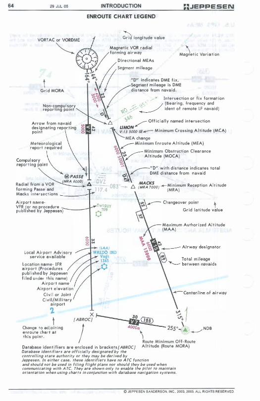
64 29 JUL 05 INTRODUCTION ::JEPPESEN
ENROUTE CHART LEGEND
VORTAC or VORDM� ;;;a longi tude value
"'" Magnet ic VOR radial "--- V forming airway o . D irectional MEAs
I II Segment mi leage ��O ! "0" indicates DME f ix.
M '\ . V ' , agnet lc ar lat lon
� Grid MORA
Non·compul sory reporting po int
Arrow from navaid des ignating report ing po int
Meteorological report required
\ distance from navaid. �segment m i l eage is DME
"'.- t" <8�� r, /� Intersection or f ix format ion o , . � ,;;.. \'f:" / (Bearing, frequency and �, \<C .. G/�// � ident of remote LF navaid) O� / b Ls./ '>:,!;' /" Off ic ia l ly named intersection
LIMON V·IS 5000 SE_ Min imum Crossing A l t i tude (MCA)
MEA ch"nge CT � Minimum Enroute A l t i tude (MEA)
� t". ,....-- Minimum Obstruction C learance
.... "'/ Alt i tude (MOCA)
� Compul sory \ reporting point �
@PASSE � ;..\ .,...-- "0" with d is tance indicates tolal
�/ DME di stance from navaid
Radi,,1 from a VOR (MRA 6000)
_ A. LilZ -- Ob 0 J 4
MACKS M' , R ' AI ' d f:::, (MRA 7000) � ," Imum ecept lon t l lu e forming Passe and M"cks i ntersect ions ____ �
(MRA)
Ai rport name· VFR (or no procedure publi shed DY Jeppesen')-------r Tw!ggy
0709 � .v-- Changeover po int t
Gr id lati tude value
Local Airport Adv i sory service "v"ilable
location name· IFR airport (Procedures pub I i shed by Jeppesen f i led under this name)
Airport name Airport el evation
C i v i l or Joint Civi l/Mi l i tary
a i rport
1 t
Change to adjoin ing enroute chart at this point .
'" 0 '" 0 ... o
Maximum Author i zed Al t i tude (MAA)
x �..!.!.� � 1 [ABROC] � "", / 4000a 2550 .. � . NOB
\ - ...,' -+---"
Route Minimum Off· Route A l t i tude (Route MORA) Database identif iers are enclosed in brackets [ABROC]
Database identifiers are officially designated by the controlling state authority or they may be derived by Jeppesen, In either case, these identifiers have no A TC function and should not be used in filing flight plans nor should they be used when communicating with A TC. They are shown only to enable the pilot to maintain orientation when using charts in conjunction with database navigation systems.
© JEPPESEN SANDERSON, INC., 2003, 2005. ALL RIGHTS RESERVED.

INTRODUCTION ENROUTE CHART LEGEND HIGH ALTITUDE CHARTS
1 DEC 0 1
The fol low ing legend. appl icable t o H i g h A l t i tude Charts onl y . is in add i tion t o the preceding legend. Many Items In the preceding legend are also applicable to the High Altitude Charts.
r-
VHF, LfMF Navigational Faci l i t ies.
VHF \ \ "w \ \. � �) �
Geographical coordinates ( l a t i tude and longitude) of each faci l i t y are shown across the bottom of the faci l i ty box. The letter ( H ) indicates an H -class fac i l ity. The letter (L) indicates an L-class f ac i l i ty . The letter (T) indicates a T-class faci l i ty. The let ter "0" indicates the avai lab i l i ty of OME . In areas of congestion, off-route fac i l i ty geographical coordinates are shown In an al phabet i cal l ist ing elsewhere on the char t .
r::AlAMOSA-;, I D 1.!3.J.. ��S I "37 20.9 Wl0S 40.9
MIAMI Center (R) 1 19.82 124.7 125.07 126.52 128.22 128.65 132.2 133.9 134.8 135.07 135.2
CTERPS:=l IIH) l1 !.:i IrS I "30 39.0 W093 45.4
L- *Flt Wetch 132.12
US High A l t i tude A i r Route Tra f f i c Control Center communi cations frequencies in Communi cations Tabulations on chart end pane l . " F l ight Watch" (Enroute F l i gh t Advisory Service) at the end of the frequency array. Service is provided between 0600 and 2200 dai l y .
-(1500-0300 UTe)
One-way preferred route 24 hours unless hours are indicated. Two- way during other hours.
25000 Fl 250
AREA CHARTS
MEA (Minimum Enroute A l t i tude) shown only when higher than f l oor of the high a l t i tude structure.
The fol lowing legend. appl icable to Area Charts on ly. i s i n add i t i on to the preceding legends. Many i tems In the preceding legends are also appl icable to the Area Char ts.
Departure route.
Arrival route.
Arrival & Departure on same route.
Speed Limit Point-Speed restr i c t i on on shaded s i de of symbo l .
0 0 $
�1231'
A i rport d iagram showing runways of major a i r ports only.
Other airports are shown by g reen symbol s .
Man-made structure having a height of 1000 feet or more above ground leve l . The elavat l on is above mean sea level .
Communications frequencies for the major ai rports shown on an Area Chart are g i ven in a block as i l l ustrated below.
COMMUNICATIONS SEATTLE, WASH S •• t l l e -Tacoma Inll. ApplCep (076'-160' Rwy 16, 341'-075' 1 19.2) ( 199'-300' 120. 1 ) (301 '-340' Rwy 34 120.4) (076'-160' Rwy 34, 30 1 '-340' Rwy 16 125.9) (161'-198' 126.5).Twr 1 1 9.9. Gnd 1 2 1.7.
Boeing Field/King Co Inti . S .. t t l e App(RII Oep(R) (076'-160' Rwy 13. 34 1'-075' 1 19.2) ( 1 99'-300' 120. 1 ) (301'-340' Rwy 31 120.4) (076'-160' Rwy 31, 301'-340' Rwy 1 3 125.9) 1 1 6 1 '-198' 126.5). Boeing 'Twr ( 1 28'-308' 120.6) (309'-127' 1 1 8.3). Gnd 121 .9
7 1
© JEPPESEN SANDERSON, INC., 1987, 2001. All RIGHTS RESERVED,
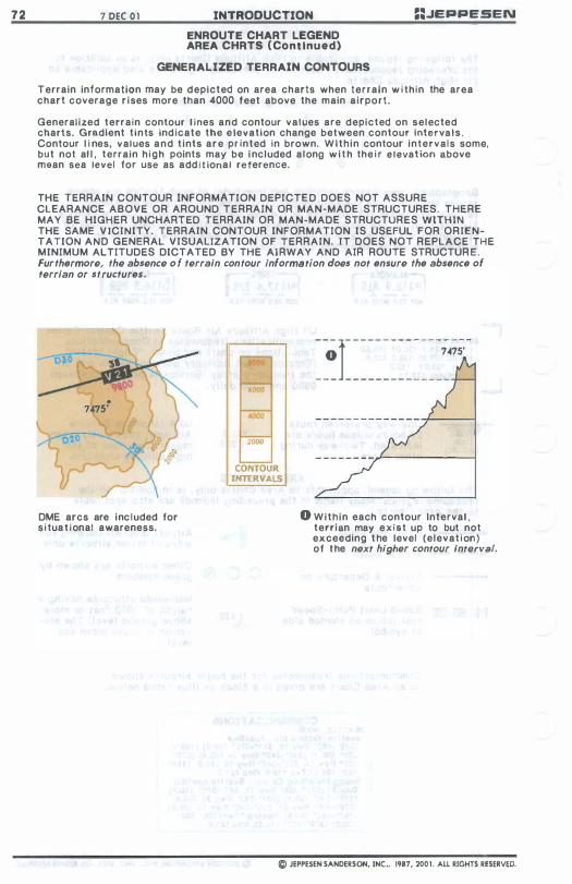
7 2 7 DEC 0 1 INTRODUCTION
ENROUTE CHART LEGEND AREA CHRTS ( Continued)
==.JEPPESEN
GENERALIZED TERRAIN CONTOURS
Terrain information may be depleted on area charts when terrain w i th in the area chart coverage r ises more than 4000 feet above the main a irport.
Generalized terrain contour l ines and contour values are depicted on selected charts. Gradient t ints indicate the e levation change between contour Intervals . Contour l i nes, values and t ints are pr inted in brown. With in contour interva ls some, but not al l , terrain h igh paints may be i ncluded a long w i t h the i r elevation above mean sea level for use as add i t ional reference.
THE TERRAIN CONTOUR INFORMATION DEPICTE D DOES NOT ASSURE CLEARANCE ABOVE OR AROUND TERRAIN OR MAN-MADE STRUCTURES. THERE MAY BE HIGHER UNCHARTED TERRAIN OR MAN-MADE STRUCTURES WITHIN THE SAME V ICINITY. TERRAIN CONTOUR INFORMATION IS USEFUL FOR ORIENTATION AND GENERAL V ISUALIZATION OF TERRAIN. IT DOES NOT REPLACE THE MINIMUM ALTITUDES DICTATED BY THE AI RWAY AND AIR ROUTE STRUCTUR E . Fur thermore, the absence o f terrain contour information does not ensure the absence of terrian or structures.
DME arcs are inc luded for s i tua t i onal awareness.
�ooo
CONTOUR INTERVALS
- - -1- - - - - - - - - - - - - - - - -
o 7475'
- - - - - - - - - - - - - - - - -
- - - - - - - -.�--------�
o With in each contour Interval , terrlan may exist up to but not exceeding t he level (elevat i on) of t he next higher contour Interval.
© JEPPESEN SANDERSON, INC .. 1987, 200 1 . All RIGHTS RESERVED.
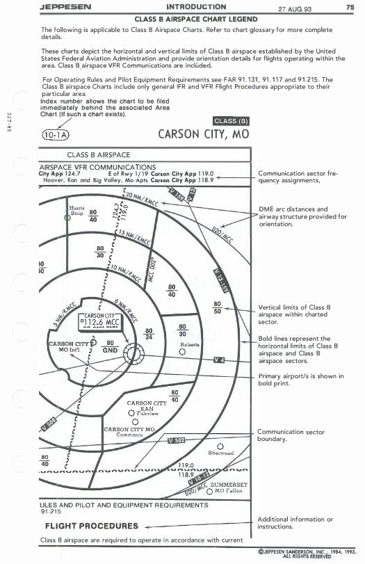
.JEPPESEN INTRODUCTION 27 AUG 93 75 CLASS B AIRSPACE CHART LEGEND
The following is applicable to Class B Airspace Charts. Refer to chart glossary for more complete details.
These charts depict the horizontal and vertical limits of Class B airspace established by the United States Federal Aviation Administration and provide orientation details for flights operating within the area. Class B .airspace VFR Communications are included.
For Operating Rules and Pilot Equipment Requirements see FAR 91 . 1 31 , 91 . 1 1 7 and 91.215. The Class B airspace Charts include only general IFR and VFR Flight Procedures appropriate to their particular area. Index number allows the chart to be filed immediately behind the associated Area Chart ( If such a chart exists).
/ ia,�sri-iWi (lO- l A) CARSON C ITY, MO
CLASS B AIRSPACE AIRSPACE VFR COMMUNICATIONS City App 1 24.7 E of Rwy 1 / 1 9 Carson City App 1 1 9.0 Communication sector fre-
Hoover, Kan and Big Valley, Mo Apts Carson City App 1 1 8.9 �---+ quency assignments,
DM E arc distances and airway structure provided for orientation.
Vertical limits of Class B airspace within charted sector.
Bold lines represent the horizontal limits of Class B airspace and Class B airspace sectors.
Primary airportls is shown in bold print.
�� .. �b::::d����:;�1LUffi�/t�����r Communication sector
_
boundary.
ULES AND PI LOT AND EQU IPMENT R EQUIR EMENTS 91 .21 5
FLIGHT PROCEDURES Class B airspace are required to operate in accordance with current
Additional information or instructions.

INTENTIONALl Y
LEFT
BLANK

INTRODUCTION 1 SEP 00
SID/DP AND STAR LEGEND The fol lowing legend is a p p l i ca b l e to Standard Instrument Departure ( S I D ) , Departure ( D P ) , Standard Terminal A r r i v a l ( S T A R ) and A r r i v a l Charts. R e f e r to the C h a r t G l ossary f o r more complete d e f i n i t ion of terms.
These charts are graphic i l l ustrat ions of the procedures prescri bed by the governing authority. A text desc r i p t i on may be prov ided, i n add i t ion to the graphic, when i t i s furnished by the governing autho r i t y . Not all i tems apply in all areas.
A l l charts meet FAA requirements for aeronautical charts. Al l a l t i tudes shown on SID/DP and STAR charts are MSl, unless otherwise spec i f ied.
COMMUNICATIONS AND ALTIMETER SETTING DATA Departure Control frequencies are Included w i t h SlDs/DPs. The f requencies a r e l i sted in the heading of the chart or when frequency sectors are speci f i e d they may be d i s p l ayed in the p l anvlew of the chart. \
HEADING I TERPS Departure (R) 1 26 . 9 \ \
PLAN V I E W \ \ sector boundary � \ symbol \ \
The ATiS frequency is provided on STARs i n the heading of the char t .
I ATIS 1 2 0 . 3
The Tran s i t ion Level and Transit ion A l t i tude a r e l i sted b e l ow the Communicat ions. For a complete explana t i on of Trans i t ion Level and Trans i t ion A l t i tude see Introduction page 103.
TRANS lEVel: Fl 1 40 TRANS Al T: 1 3000 '
CHART IDENTIFICATION STARS SIDS/DPa
@}) (1 0-2A) , etc. Index number Gffi (1 0-3A) , etc. Index number
� � Spec i a l chart issued to speC i a l coverages only. � � Contains mod i f i ed i nforma t i on for your company. IIDlI Standard Terminal Arrival
lID Standard Instrument Departure
",Ji'I",' A r r i v a l Procedure 1ImII 1.'I143.1,;I' Departure Procedure
ROUTE IDENTIF ICATION TYPICAL EXAMPLES USING COMPUTER LANGUAGE
STARS
MOORPARK FOUR ARRIVAL (FIM.MOOR4) l A r r i v a l Name A r r i val Code .J
FRESNO ( FAT.MOOR4) + +
Trans i t ion Name Trans i t i on Code SID/DP
MIllS (ROCKI l .MILlS) Transi t ion Name J Transi tion Code J
PI LOT NAV SID/DP VECTOR SID/DP
DENVER FIVE DEPARTURE (DEN5.DEN) (VECTOR)
8 1
DeRaotc�tON? DEPARTURE (ROCKI 1 .ROCKI) (PILOT NAV) Departure Code J t Pr imary Nav i g a t i on is by p i l o t , not radar
SID/DP where ATC provides radar nav i g a t i onal guidance to an assigned route o r to a fix depicted on the SID/DP. Vector S I DS/DPs indicate the fix or route to which the pi lot w i l l be vectored
TYPICAL EXAMPLES NOT USING COMPUTER LANGUAGE STARS SID lOP
ALPHA ARRIVAL (RWY 1 0) .., A r r i val Name J Spec i f i ed runway to be used
� RUNWAY 1 3 ARRIVAL
INDIA DEPARTURE f' Departure Name J
RUNWAY 1 3 DEPARTURE Database ident i f i e r are i nc l uded when d i f ferent than the name or computer code. The database iden t i f i e r i s enclosed in brackets.
POGO NORTH 7X DEPARTURE [POGN7Xj
© JEPPESEN SANDERSON, INC., 1984, 2000. ALL RIGHTS RESERVED.

8 2
RADIO SYMBOLS
(0 o o
..(()� �
F�.um--#//��� ��h«��
1 SEP 00 INTRODUCTION
SID/DP AND STAR LEGEND GRAPHIC
(Charts are not drawn a t a spec i f i c s c a l e )
VORTAC/vORDME
VOR (VHF Omn i d i r ect ional Range)
RADIO IDENTIFICATION
TACAN (Tac t ical A i r iPRACH'NBUR'l Navigat ion ) o r D M E ( D i s t - 201 PB ance Measur i ng E q u i pmen t ) • __ • _ •••
Navaid i de n t i f icat ion is g i ven i n shadow box w i t h f r equency, i den t i f i e r , Morse Code and l a t i tude & longi tude coor d i na t es. DME capa b i l i t y i s i nd i cated by a sma l l "D" p r eceding the VOR f r equency a t f r equency paired nava i d s . VOR and VORTAC f a c i l i ty operat ional ranges are ident i f ied (when known) w i t hi n t he navaid box. ( T ) represents Term i n a l ; (l) r e presents low A l t i tude; and ( H ) rep resents H i g h A l t i tude.
N D B (Nond i rect ional Rad i o Beacon)
LOC, LDA, or SDF F ront Course
lOC Back Course
locator w i t h Outer Marker (lOM)
Outer or Middle Marker ( O M ) ( M M )
N14 06.0 E l01 22.0
LOC local izer navaids are ident-
f](i8 7 1Mii$' i f i e d by a round cornered box. �'- -!!."?U Frequency ident i f i ca t i o n and
£DC (BACK CRS) 0890 1 09.7 1M EX (FRONT CRS 2690 )
Morse Code are provided. D M E is i nc l uded w h e n nava i d a n d DME are f r equency p a i r ed . loc a l izer back course faci l i ty boxes i n c l ude front course bearing for HSI s e t t i n g .
AIRSPACE FIXES
� {> X - Non-Compulsory A i rspace f i xes.
Il.. + - Compulsory A i r space f i xes.
@@@@@- F l y-over A i rspace f i xes.
VERTICAL NOISE ABATEMENT PROCEDURES
Ver t i c a l Noise Abatement Procedures ( V N A P ) . F o r explanation of procedures, s e e A i r Traf f i c Cont rol sect ion.
RESTRICTED AIRSPACE
PROHIBITED, RESTRICT E D , DANGER AREAS Proh i b i ted, Restr i cted & Danger Areas are charted when ref erenced i n SID/DP or STAR source, p l us any Proh i b i ted Area w i t h i n f i ve (5 ) naut i c a l mi les of route cente r l ine o r pr imary a i r por t .
DeS i g n a t i on (Type of a r e a can R · 27 ! � ---
be determined by P-Prohib ited, � ............ R-Res t r i cted, D-Dang e r . ) � Upper l i m i t loeOO.2200 � lower l i m i t
Mltl-SAr Hours act ive r�, Mm:' - Contro l l i ng Agency
ROUTE PORTRAYAL
S I D / DP and STAR Track
BOLES __ Transi t i on name
{REX.BOLES3, __ Route. i�ent i f i c a t i on code �---::::I"" +- Trans l t lon track I'1fO - M i n imum E n route A l t i tude (MEA) -- Segment m i l eage Cross at TL+ 1 0
and descend fO 3000'
SID/DP or STAR label of a par t i cu l a r r o u t e i n some coverage areas
uuuuUmllUUIUJllnmmU ,>Radar vec t o r i ng .. .. .. .. � -/ '��ns Q' ___ P r i mary a r r i v a l or departure a i r po r t .
V i sual f l ight track /7500 hrt -+--- F l ight path segment f lown � w i t h head i ng only .
© JEPPESEN SANDERSON, INC . , 1984, 2000. All RIGHTS RESERVED.
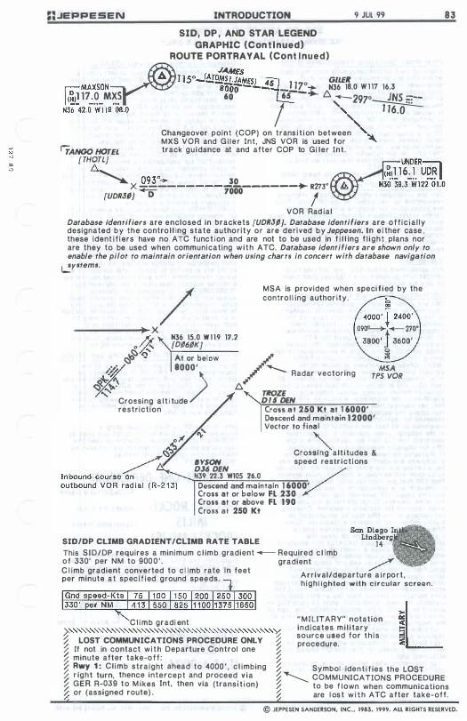
:;JEPPESEN INTRODUCTION 9 JUL 99
SID, DP , AND STAR LEGEND GRAPHIC (Con t i nued)
ROUTE PORTRAYAL (Cont i nued) �1150_(eo�1fi�SM � GILER �MAXSON aooo..!S1...!5 -DZ:- N36 18.0 Wll7 16.3 I (�� 17.0 MXS 60 65 '" /:::,. --2970 JNS :..�--N3r;-42.0·wi1S·OS.0
I" � "
Changeover point (COP) on trans i t ion between ',,-
MXS VOR and Gi ler Int, JNS VOR is used for ,
IrANGO HOTEL track guidance at and after COP to Gi ler Inl. [THOTL)
/:::,. � X .Q.�,r:�· ______ J'!!" ______ � R273°
[UDRJI} ..., 7000 /
VOR Rad ial Database identifiers are enclosed in brackets [UDRJ/}. Database identifiers are off ic ia l ly designated by the contro l l ing state author ity or are derived by Jeppesen. In e i ther case , these ident i f iers have no ATC func t i on and are not to be used in f i l l ing f l ight plans nor are they to be used when communicating w i t h ATC. Database identifiers are shown only to enable the pilot to maintain orientation when using charts in concert with database navigation �ystems.
/ MSA is provided when specif ied by the contro l l ing author i ty .
-----.... X Jf.. N36 IS.0 W119 17.2
o {f:. [D/6/K} f::l� Q' At or below
.'�' 1000' .;;�z ) � .".� ,"-'
/� Radar vectoring
/:::,. TROZE 0'5 DEN
MSA TPS VOR
Crossing a l t i tude restr ict ion Cross at 250 Kt at 1 6000'
Descend and maintain 1 2000' Vector to f ina l
" Crossing alt i tudes &
BYSON speed restr ict ions 036 DEN
V
N39 22.3 Wl0S 26.0 Descend and maintain t 6000' Cross at or below Fl 230 Cross at or above Fl 1 90 Cross at 250 Kt
SID/DP CLIMB GRADIENT/CLIMB RATE TABLE
This SID/DP requires a minimum c l imb gradient __ Required c l imb of 330' per NM to 900 0 ' . gradient /'" C l imb gradient converted to c l imb rate In feet per minute at spec i f ied ground speeds. Arr ival/departure a i r port ,
C I imb gradi ent >""""""""""""""""""""""""''Y � LOST COMMUNICATIONS PROCEDURE ONLY � % If not in contact w i t h Departure Control one %
highl ighted with c i r cular screen.
" M ILITARY" notation indicates m i l i tary source used for th is procedure.
� minute after take-off : � � Rwy 1 : Climb straight ahead to 4000 ' , c l imbing � Symbol iden t i f ies the LOST
83
� r ight turn, thenc.e intercept and. proceed. � ia �� COMMUNICATIONS PROCEDURE � GER R-.039 to M ikes Int, then via (transi t i on) � to be f lown when communications % or (aSSigned route) . � are l os t w i t h ATC after take-off.
© JEPPESEN SANDERSON, INC., 1983, 1999. ALL RIGHTS RESERVED.
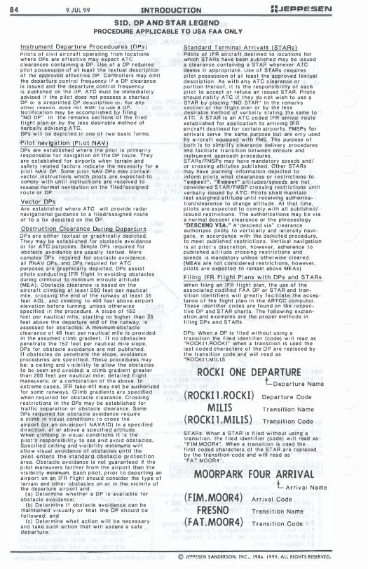
84 9 JUL 99 INTRODUCTION =:JEPPESEN
SID. DP AND STAR LEGEND PROCEDURE APPLICABLE TO USA FAA ONL Y
Instrument Departure Proceduures (DPs) P i l o t s of c i v i l a i r c r a f t operating f rom locations where CPs are e f f ective may expect ATe c l earances containing a OP. Use of a DP requires pi lot possession of at least t h e textual descript ion of the approved effective DP. Control l ers may ornit the departure control frequency i f a DP clearance is issued and the departure control frequency is published on tho OP. ATe must be immediatel y advised if the pi lot does not possess a charted DP or a preprinted DP description or. for any other reason, does not wish t o use a DP. Notif ication may be accomp l i shed by f i l ing " NO DP" in the remarks sec t i ons of the f i l ed f l ight plan or by the less desirable method of verbally advising ATC. DPs w i l l be depicted i n one of two basic forms.
P i lot navigation (P i l o t NAV) DPs are established where t h e pi lot is primar i l y responsible f o r navigation on t h e DP route. They are established for airports when terrain and safety related factors indicate the necessity for 8 p i l o t NAV DP. Some p i l o t NAV DPs may contain vector instructions which pilots are expected to comply w i t h unti l instructions are received to resume normal navigation on the f i l ed/assigned route or DP.
Vector DPs Are established where ATe will provide radar navigational guidance to a fi led/assigned route or to a fix depicted on the OP. Obstruction Clearance During Departure
D P s a r e either textual or graphica l l y depicted. They may be established for obstacle avoidance or for ATC purposes. Simple DPs required for obstacle avoidance are usually textual. More complex DPs required for obstacle avoidance, all ANAV DPs, and DPs required for ATC purposes are graphical l y depicted. DPs assist pilots conducting IFR flight in avoiding obstacles during cl imbout to minimum enroute a l t itude (MEA). Obstacle clearance i s based on t h e aircraH c l imbing at l e a s t 2 0 0 feet per nautical mile, crOSSing the end of the runway at least 35 feet AGL, and climbing to 400 feet above airport elevation before turning, unless otherwise specified in the procedure. A slope of 152 feet per nautical mile, starting no higher than 35 feet above the departure end of the runway, is assessed for obstacles. A minimum obstacle clearance of 48 feet per nautical mile is provided in the assumed c l imb gradient. I f no obstacles penetrate the 152 feet per nautical m i l e slope, OPs for obstacle avoidance are not published. I f obstacles do penetrate t h e slope, avoidance procedures are speCified. These procedures may be: a cei l ing and v i s i b i l i ty to al low the obstacles to be seen and avoided; a climb gradient greater than 200 feet per nautical mi le; deta i l ed f l ight maneuvers; or a combination of the above. In extreme cases, IFR take-aU may not b e authorized for some runways. Cl imb gradients are specified when required for obstacle c l earance. Crossing restrictions in the OPs may be established for traffic separation o r obstacle clearance. Some OPs required for obstacle avoidance require a cl imb in visual conditions t o cross the airport (or an on-airport NAVAIO) In a specif ied d i r ection, at or above a specif ied a l t i tude. When c l imbing in visual conditions i t Is the pi lot's responsi b i l i t y to see and avoi d obstacles. Specified ceiling and visibi l i tv minimums w i l l a l l o w visual avoidance of obstacles u n t i l the pilot enters the standard obstac le pr o tect ion area. Obstacle avoidance is not guaranteed if t h e p I lot maneuvers f a r t h e r f r o m the ai rport than t h e v i s i bi l i ty minimum. Each pilot, p r i o r t o departing an ai rport on an I F A f l ight should consider the type of terrain and other obstacles on or in the vicinity of the departure a i rport and:
( a ) Determine whether a DP i s avai l a b l e for obstacle avoidance;
(b) D e t e r m i n e I f obstacle avoidance can be maintained v i sual ly o r that the DP should b e f o l lowed; and
(c) Determine what action w i l l b e necessary and take such action that w i l l assure a safe departure.
Standard Terminal A r r i vals (STARs) Pilots of I F R aircraft destined to locations for which STARs have been published may be issued a clearance containing a STAR whenever ATC deems it appropriate. Use of STARs requires pi lot possession of a l least the approved teKlual description. As w i t h any ATC c l earance or portion thereof, i t Is the responsi b i l i ty o f each pi lot to accept or refuse an I ssued STAR. Pi lots should notify ATe i f they do not wish to use a STAR by placing "NO STAR" In t h e remarks section of the fl ight plan or by the less desirable method of verbal l y stating the same to ATe. A STAR is an ATe coded IFR arrival route Bstab l i shed for appl ication to arriving IFR aircraft destined f o r certain airports. FMSPs for arrivals serve the same purpose but are o n l y used by ai rcraft equipped with FMS. The purpose of both is to simp l i f y clearance delivery procedures and faci l ia t e transition between enroute and instrument approach procedures. STARs/FMSPs may havB mandatory speeds and! or crossing altitutes publ i shed. Other STARs may have planning information depicted to inform pi lots what cl earances or restrict ions to "expect". IJExpect" a l t i tudes/speeds are not considered STAR!FMSP crossing rest r i c t i ons until verba l l y issued by ATC. Pilots Sha.1I maintain last assigned a l t i tude un t i l receiving authorization/clearance to change al t itude. At that t ime, p i lots are expected to comply w i t h a l l published/ issued restrictions. The authorizations may b e via a normal descent clearance or the phraseOlogy "DESCEND VIA." A"descend via" c l earance authorizes pilots to vert ical ly and lateral ly navigate, in accordance with the depicted procedure, to meet published restrictions. Vertical navigation is at p i l o t ' s discretion, however, adherence to published a l t i t ude crossing restr ictions and speeds i s mandatory unless otherwise c l eared. (MEAs are not considered restrictions, however, p i lots are expected to remain above ME As)
F i l ing [FR F l ight P l ans w i t h DPs and STARs When filing an IFR f l ight plan, t h e use of the associated codified FAA DP or STAR and trans i tion identifiers w i l l greatl y f a c i l itate the acceptance o f the f l ight plan i n the ARTCC computer. These identifier codes are found on the respect i ve DP and STAR charts. The following explanation and examples are the proper methods in f i l i ng DPs and STAAs.
DPs: When a DP is f i l ed wi thout using 8 transition the f i led iden t i f i e r (code) w i l l read as "ROCK I 1 . ROCKI" When a transition is used the last coded characters of the D P are replaced by the transition code and will read as "AOCK l l .MILlS
ROCKI ONE DEPARTURE L Departure Name
(ROCKI 1 .ROCKI) Departure Code
MIllS Transition Name
(ROCKI l .MILIS) TranS i t i on Code
STARs: Whan a STAR is f i led w i thout using a transi t ion. t h e f i led ident i f i er (code) w i l l read as "FIM.MOOR4". When a transition is used the f i rst coded characters of the STAR are replaced by the transition code and w i l l read as "FAT.MOOA4".
MOORPARK FOUR ARRIVAL L A r r i v a l Name
( F IM.MOOR4) A r r i val Code
FRESNO Trans i t ion Name
( FAT.MOOR4) Trans i t i on Code
© JEPPESEN SANDERSON, INC" 198 •• 1999. ALL RIGHTS RESERVED.
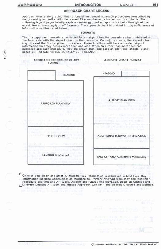
JEPPESEN INTRODUCTION 10 MAR 95 1 0 1
APPROACH CHART LEGEND
Approach charts are graphic i l l ustrat ions of instrument approach procedures prescr i bed by the governing author ity. A l l charts meet FAA requirements for aeronautical charts . The f o l l ow i ng legend pages br ief ly explain symbology used on approach charts throughout the wor ld. Not aI/ items apply to aI/ locations. The approach chart i s d i v i ded into specif ic areas of information as i l l ustrated below.
FORMATS
The f i rst approach procedure publ ished for an airport has the procedure chart published on the f ront s ide w i th the a i r port chart on the back s ide. On major a irports , the a i rport chart may proceed the f i rst approach procedure. These locat ions w i l l have expanded a i rport i nformat i on that may occupy more than one s ide. When an airport has more than one pub l ished approach procedure, they are shown front and back on add i t i onal sheets. B l ank pages wil l indicate "INTENTIONALLY LEFT BLAN K " .
APPROACH PROCEDURE CHART FORMAT
I HEADING
APPROACH PLAN VIEW
PROFILE VIEW
LANDING MINIMUMS
AIRPORT CHART FORMAT
HEADING I
AIRPORT PLAN VIEW
ADDITJONAL RUNWAY INFORMATION
TAKE-OFF AND ALTERNATE MINIMUMS
r-On charts dated on and after 10 MAR 95, key information is d i s p l ayed in bold type. Key information includes Communicat ion frequenc ies, Pr imary NAVAID frequency and ident i f ier , Procedure bearings and A l t i tudes, Ai rport and runway end e levation, Dec i s i on A l t itude and
l-M inimum Descent A l t i tude, and M issed Approach turn l im i t and d i rection, course and a l t i tude.
© JEPPESEN SANDERSON, INC., 1984, 1995. ALL RIGHTS RESERVED.
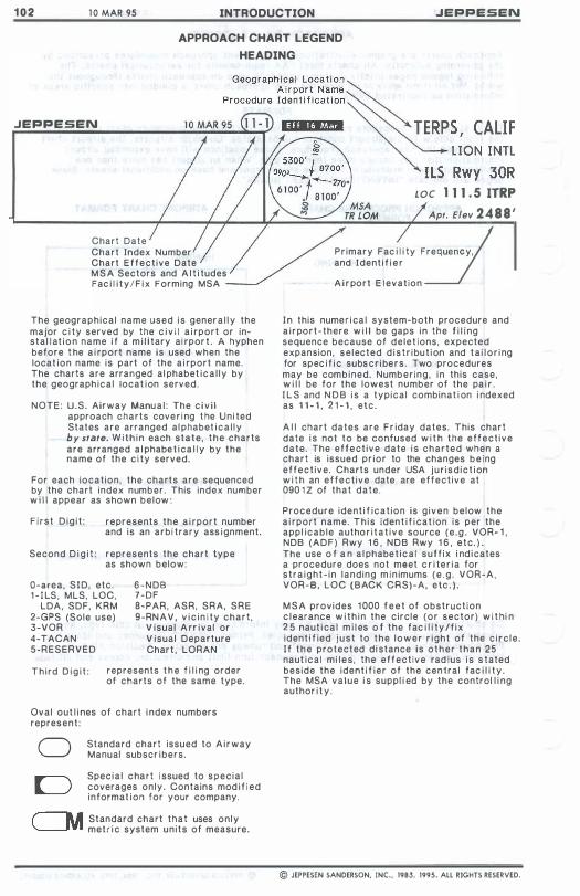
1 0 2 1 0 MAR 9S INTRODUCTION .JEPPESEN
APPROACH CHART LEGEND
HEADING
.JEPPESEN
LOC 1 1 1 . 5 ITRP Apt. Elev 2 4 8 8 '
Chart Date y � Chart Index Number P r imary Fac i l i ty Frequency, Chart E f fect ive Date and Ident i f i e r M S A Sectors and A l t i tudes Fac i l i t y / F i x Forming MSA A i r po r t E l evation
The geographical name used i s gener a l l y the major c i ty served by the c i v i l a i rport or instal l at i o n name i f a m i l i tary ai rpor t . A hyphen before t he a i rport name is used when the locat ion name is part of the a i rport name. The charts are arranged al phabet i c a l l y by the geograph ical locat i on served.
NOTE: U.S. Airway Manu a l : The c i v i l approach charts cove r i ng t he Uni ted States are arranged al phabet i c a l l y by state. W i t h i n each state, t h e charts are arranged a l phabe t i ca l l y by the name of the c i ty served.
For each location, the charts are sequenced by the chart index number. This index number w i l l appear as shown below :
F i r s t D i g i t : represents the a i rport number and is an arbi trary ass i gnment.
Second D i g i t : represents the chart type as shown below:
O-area, SID, etc. 1 - I LS , MLS, LOC,
LDA, SDF, KRM 2-GPS (Sale use) 3-VOR 4-TACAN 5-RESERVED
6-NDB 7-DF 8-PAR, ASR, SRA, S R E 9-RN A V . v i c i n i ty chart ,
V i sual A rr i val or V i sual Departure Char t , LORAN
T h i rd D i g i t : represents t h e f i l i ng order of charts of the same type.
Oval out l i nes of chart i ndex numbers repres ent :
o Standard chart issued to A i r way Manual subscr i bers .
Spec i a l c ha r t i ssued to specia l coverages only. Contains mod i f i ed informat ion for your company.
,-----.. Standard chart that uses only '---JYI mell i c system units of measure.
I n this nume r i ca l system-both procedure and a i r po r t -there w i l l be gaps i n the f i l i ng sequence because of d e l e t ions, expected expansion, s e l ected d i s t r i bu t i on and t a i l o r i ng for spec i f i c subs c r i be r s , Two procedures may be com b i ned. Numb e r i n g , i n this case, w i l l be for the lowest number of the pa i r . I L S and N D B i s a typical combinat i on i ndexed as 1 1 - 1 . 2 1 - 1 , etc.
A l l chart dates are F r iday dates. This chart date i s not to be confused w i t h the effect ive date. The effect ive date i s charted when a chart is issued p r i o r to the changes b e i ng effect ive . Charts under USA j u r i s d i c t i on w i t h an effect ive date are effect ive at 090 1 Z of that date.
Procedure ident i f icat ion is g i v e n below the a i rport name. T h i s iden t i f i cat ion is per the appl icable autho r i t a t i v e source ( e . g . VOR- l , NDB ( A D F ) Rwy 1 6 , N D B Rwy 1 6 , e t c . ) . The use o f a n a l phabe t i c a l s u f f i x i nd i cates a procedure does not meet c r i te r i a for s t r a i g h t - i n landing m i n imums ( e . g . VOR-A. VOR-B. LOC ( B ACK CRS)-A. etc . ) .
M S A provides 1 000 f e e t of obstruction c l earance w i t h i n the circle ( o r sector) w i t hi n 2 5 naut i ca l m i l es o f the fac i l i ty / f i x ident i f ied j u s t to t h e l o w e r r i ght of the c i r c l e . I f t h e protected di stance is o t h e r t h a n 25 naut ica l mi l e s , the effect ive rad i us i s s tated beside the ident i f i e r of the central fac i l i t y. The MSA value i s suppl i ed by the control l i ng author i t y .
© JEPPESEN SANDERSON, INC., 1983, 1995. ALL RIGHTS RESERVED.
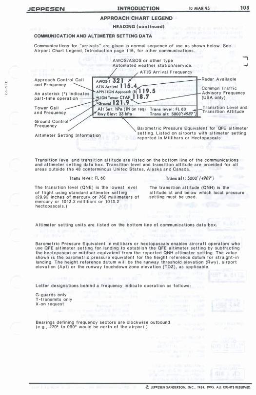
JEPPESEN INTRODUCTION 10 MAR 95 APPROACH CHART LEGEND
HEADING (conti nued)
COMMUNICATION AND ALTIMETER SETTING OAT A
Communications for "arr i va ls" are g i ven in normal sequence of use as shown below. See Airport Chart Legend, Introduction page 1 1 6 , for other communications.
AWOS/ ASOS or other type Automated weather station/service.
ATiS Arr i va l F requency
__ -------r Radar Availaole
103
Approach Control Ca l l and Frequency
An asterisk (0) indicates part-t ime operat ion
Common Traff ic Advisory Frequency (USA only)
Tower Ca l l and Frequency
Trans level : fL 60 Trans alt: 5000'(4987')
Trans i t ion Level and Trans i t ion Alt i tude
Ground Control Frequency
Alt imeter Sett ing Informat ion
Barometr ic Pressure Equivalent for QFE al timeter sett ing. L isted on a i rports with a l t imeter setting reported in M i l l i bars or Hectopascals .
Trans i t ion l evel and trans i t ion a l t i t ude are l i s ted on the bottom l ine of the communications and a l t imeter setting data box. Trans i t ion level and trans i t ion a l t i tude are provided for a l l areas outside the 48 conterminous Uni ted States, A laska and Canada.
Trans level : Fl 60
The trans i t ion level (QNE) is the lowest l evel of f l ight using standard a l t imeter sett ing (29.92 inches of mercury or 760 m i l l imeters of mercury or 1 0 1 3 . 2 m i l l i bars or 1 0 1 3 . 2 hectopascal s . )
Trans a l t : 5000' (4987')
The trans i t ion a l t i tude (QNH) is the a l t i tude at and below which local pressure set t ing must be used .
A l t i meter sett ing units are l isted on the bottom line of communicat ions data box.
Barometric Pressure Equivalent in mi l l i bars or hectopascals enables aircraft operators who use QFE a l t imeter setting for landing to establ i s h the QFE a l t imeter sett ing by subtracting the hectopascal or mi l l ibar equivalent from the reported QNH a l t imeter setting. The value shown i s the barometr ic pressure equivalent for the height reference datum for straight- in land ing. The height reference datum w i l l be the runway threshold elevat ion (Rwy) , a i rport e levat ion (Apt) or the runway touchdown zone e levat ion (TDZ) , as app l icable.
Letter designations behind a frequency indicate operat ion as fol lows :
G-guards only T-transmits only X-on request
Bear ings def in ing f requency sectors are clockwise outbound (e .g . , 270' to 090' would be north of the a i rpor ! . )
© JEPp�SEN SANDERSON, INC., 1984, 1995. All RIGHTS RESERVED.
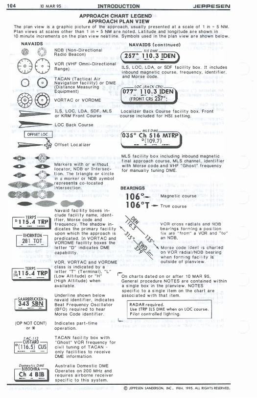
1 04 10 MAR 95 INTRODUCTION .JEPPESEN
APPROACH CHART LEGEND APPROACH PLAN VIEW
The p l an view is a graphic p i cture of the approach, usua l l y presented at a scale of 1 in = 5 N M . P l an v iews at sca l es other than 1 i n = 5 NM a r e noted. Lat i tude and long i t ude a r e shown i n 1 0 m i nute incremen ts o n t h e p l an v i e w nea t l ine . Symbols used i n t h e p l an v i ew a r e shown below.
NAVAIDS
e o
0 0 @ ©
E.t
NDB ( Non-Direct ional Radio Beacon)
VOR ( V H F Omn i - D i recl ional Range)
TACAN (Tac t ical A i r Navigat iolT fac i l i t y ) or D M E ( D i s t ance Measur ing Equipment)
VORT AC or VORDME
ILS, LOC, LDA, SOF, MLS or KRM Front Course
LOC Back Course
O f fset Loc,al izer
Markers w i t h or w i thout l ocator, N DB or [ntersec� 4(']. t i on. The t r i angle or c i rc l e
'�":'�' In a marke r or NDB symbol
!1§ffi--- .f''}.� eP T esen�s co-located ,� ,..,,�,/f I ntersectIon.
(��J. • • •
[THORNTON] 281 TOT - --- -
(OP NOT CaNT) or *
TAC· l ll �CUSTARD� 1��6.�2 C�
Domes tic DME nBIBOOHRA� f.� �. B!!
Navaid fac i l i t y boxes i n-c l ude fac i l i t y name, identi f i e r , Morse code and f r equency. The shadow ind i cates the pr imary fac i l i ty upon which t he approach is predicated. In VORTAC and VORDME fac i l i t y boxes the l e t t e r "0" i nd i cates OME capab i l i ty .
V O R , VORTAC a n d VORDME c l ass i s i nd i cated by a l e tter "T" (Termina l ) , " L " ( Low A l t i t ude) o r " H " ( H i g h A l t i t ude) when ava i l a b l e .
Under l i ne shown below navaid ident i f i e r , indicates Beat F requency Osci l I ator (BFO) requi red to hear Morse Code ident i f i e r .
Indi cates par t - t i m e operation.
TACAN faci l i ty box w i t h "Ghost" V O R f requency for c i v i l tuning of TACAN -only faci l i t i e s to receive OME information.
Austral i a Dome s t i c DME Operates on 200 MHz and requires a i r borne rece i v er spec i f i c to t h i s system.
NAVAIDS (con t i nued) ILS DME
em: 1J.O •. 3]>EN) [LS, LOC, LOA, or SOF faci l i ly box . [I includes i nbound magnetic course, frequency, ident i f i er , and Morse code.
Local izer Back Course fac i l i t y box. Front course i nc l uded for HS[ s e t t i ng .
MLS DME, ___ _
"-O"""'35-o-Ch 5 1 6 MTRP ° ( 109.7)
MLS fac i l i ty b o x i nc l ud i ng inbound magne t i c f inal approach course, M L S channe l , ident i f i er with Morse code and V H F "Ghost" f r equency for manua l l y tuning D M E .
BEARINGS
Magne t i C course
1 0601 -- True course
/,/. � VOR cross r ad I a I s and NDB � If '" 'J' be a r i ng s form ing a position iJ f i x are " from" a VOR and " to" -So /J'" an NOB
,I'; '" 0
�� X M o rse code I d e n t i s charted p ,� on V O R rad i a l lNDB bear ing '.'
when form i ng fac i l i t y is outside of p l anview.
r-On c h a r t s d a t e d o n or after 1 0 MAR 95, General procedure NOTES are contained w i th i n a s i n g l e box in t he p l anv i e w . NOTES spec i f i c to a s i n g l e i t em on the chart are assoc i ated w i t h that i tem.
RADAR required. Use ITRP IlS DME when on laC course. P i lot controlled l ight ing .
© JEPPESEN SANDERSON, INC .. 1984, 1995. All RIGHTS RESERVED.
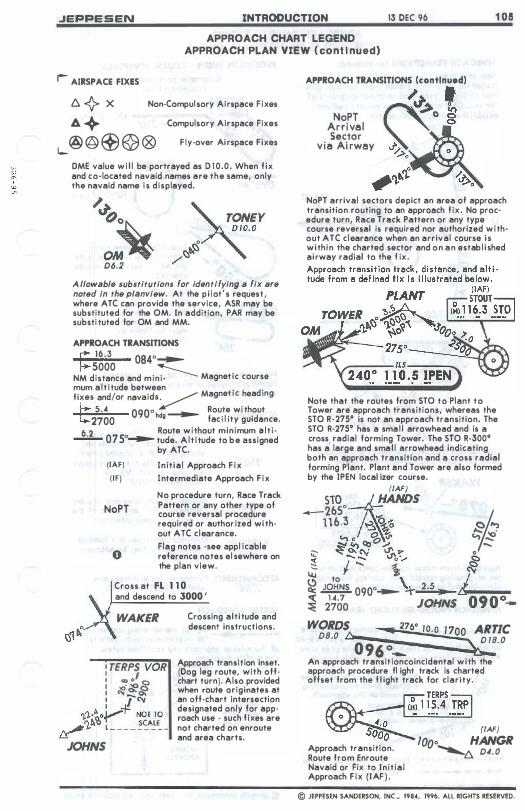
JEPPESEN INTRODUCTION 13 DEC 96 1 05 APPROACH CHART LEGEND
APPROACH PLAN VIEW ( cont i nued)
r- AIRSPACE FIXES
6. {> X Non·Compulsory Airspace Fixes
It. + Compulsory Airspace Fixes
i-@ @ � @ ® Fly·over Airspace Fixes
OME value w i l l be portrayed as 0 1 0.0. When f ix and co· located navaid names are the same, only the navaid name is displeyed.
/� ()�
OM� D6.2 /'
�ONEY D 10.0 ���
A llowable substitutions for identifying a fix are noted in the planview. At the p i lot 's request , where ATC can provide the service, ASR may be substituted for the OM. In addition, PAR may be substi tuted for OM and MM.
APPROACH TRANSITIONS � 16.3 0840� 5000 � . NM distance and mini· Magnet ic course mum a l t i tude between . . fixes and lor navaids� Magnet ic heading
� 5.4 0900 _ Route wi thout
2700 hdg fac i l ity gUidence.
6.2 0 Route without minimum a l t i · --- 075 � tude. A l t i tude to be assigned
by ATC.
(IAF)
(IF)
NoPT
o
Init ial Approach F ix Intermediate Approach F ix
No procedure turn, Race Track Pattern or any other type of course reversel procedure required or author ized wi th· out ATC clearance. Flag notes ·see appl icable reference notes el sewhere on the plan view.
Cross at FL 1 1 0 and descend to 3000 '
WAKER
I TERPS VOR I I : � � 8 I � o.. o. : I "'"
').').·kl ....... -f! NOT TO �').bi l _ _ _ _ �<::'.':�
JOHNS
Crossing alti tude and descent instructions.
Approach transition inset. (Dog leg route, with off· chart turn). Also provided wnen route originates at an off·chart intersection designated only for app· roach use · such fixes are not charted on enroute and area charts.
APPROACH TRANSITIONS (continued)
NoPT Arrival Sector
v ia Ai rwey
/ I
�. � ,,�o ...... � '').bi�� NoPT arrival sectors depict an erea of approach transition routing to an approech fix. No proc· edure turn, Race Track Pattern or any type course reversal is required nor authorized with· out ATC clearence when an arrival course is within the charted sector and on an estab l i shed airway radial to the f ix .
Note that the routes from STO to Plant to Tower are approach transitions, whereas the STO R·27So is not an approach transition. The STO R·27So has a smal l arrowhead and is a cross, radial forming Tower. The STO R·300o has a large and smal l arrowhead indicating both an approach transition and a cross radial forming Plant. Plent end Tower are also formed by the IPEN local izer course.
(IAF)
S10 ��NDS _2650
1 1 6.3 � �'O �fw) � 't, J.;;. •
"> 0 <& '" "> � ".,, � C!) ". _ ;;::- :t o.. CV -?" ... 0 �
I""""' ..... v 0'''''' � .... ...... � �
� to 2> 1" � � 0900_ \.��.&�� ......
� di;o JOHNS 090°-WORDS ........ 2760 10.0 1 700 ARTie D8.0 t:........ D 18. 0 0 96 °_ � An approach transit ioncoincidental with the approach procedure fl ight track is charted offset from the f l ight track for clarity.
Approach transition. Route from Enroute Navaid or Fix to Initial Approach F ix (IAF ) .
(IAF)
1000 HANGR � D4.0
© JEPPESEN SANDERSON, INC .• 1984, 1996. All RIGHTS RESERVED.
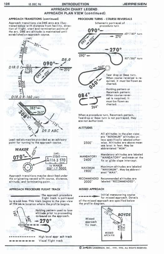
1 06 13 DEC 96 INTRODUCTION JEPPE SEN
APPROACH CHART LEGEND APPROACH PLAN V IEW ( cont Inued)
APPROACH TRANSITIONS (continued) Approach transit ions via DME arcs are i l lustrated below with distance from fac i l ity, direction of f l ight, start and termination points of the arc. DME arc alt i tude is maintained unt i l estab l i shed o n approach course.
(IAF) .( Jo, •
.... 8 -....... �� CO
05. 0 r' 090°- / D lB. O 6�11;:::O°:t::-O""-''''
NoPT --270·
Lead radl"ls may be provided as an advisory point for turning to the approach course.
Approach transitions may be described under the originating navaid with course, distance, a lt i tude, and terminating point.
APPROACH PROCEDURE FLIGHT TRACK
________ The approach procedure II ight track is portrayed
by a t.old line. This track begins in the plan view at the la, 1'4 location where the prol i le begins. ,..; [\ Holding pattern used to lose
� altitUde/,ior to proceeding
. \,'.; .... �. ':127 o� the "Pproach.
.......
• • • • • • • • • • • • • • • High level approach track ................ Visual f l ight track
PROCEDURE TURNS - COURSE REVERSALS
Schematic portrayal of procedure tUrn
090°--�----�� 45°/ 1 80° turn -- 270·
--210° ""!:0�9�0�O----
__ ---o.p "",,,"0 '"m
c:lTear drop or Base turn. .J When course reversal is re-�' qui red, it must be f lown as
� charted. � Holding pattern or
.. ° Racetrack pattern.
08� � When course rever-
e sal is required, i t must be flown as
• charted. 264
When a procedure turn, Racetrack pattern, Teardrop or Base turn is not portrayed, they are not author ized.
AlT"UDES
2300 '
MANDATORY 2400'
MAXIMUM 1 900'
Al l a lt i tudes in the plan view are "MINIMUM" a l t i tudes unless spec i f ica l ly labeled other· wise. Alt i tudes are above mean sea level in feet. May be abbreviated "MIM" .
Mandatory alt itudes are labeled "MANDATORY" and mean at the fix or gl ide slope intercept.
Maximum altitudes are labeled "MAXIMUM" . May be abbrevi · ated "MAX",
RECOMMENDED Recommended a l t itudes are 2000 ' labeled "RECOMMENDED".
MISSED APPROACH
� Init ial maneuvering course -----for missed approach. Details
of the missed approach are speci fied below the proll Ie diagram.
Missed approach f ix inset .
r__------, 1;/718 /<' /�OYOS J'o� ..... � V') :::E oo ..;
��S���x « r= @ JEP!,£SEN SANDERSON, INC . . 1991. 1996. ALL RIGHTS RESERVED.
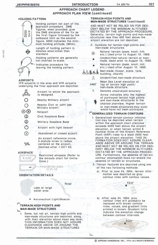
JEPPESEN I NTRODUCTION 2.01 JUN 9.01 1 0 7
APPROACH CHART LEGEND APPROACH PLAN VIEW ( cont i nued)
HOLDING PATTERN
8 Holding pattern not part of the approach procedure. DME f i gures, when provided, g i ve the DME distance of the f i x as the f i rst f i gure f o l l owed by the outbound l im i t as the second f igure. 3000 indicates the min imum holding a l t i tude, (MHA).
Length of holding pattern in minutes when other than standard.
"""- Indicates procedure for
Ir\1 leaving the holding pattern.
TERRAIN HIGH POINTS AND MAN-MADE STRUCTURES ( con t i nued)
AND MUST NOT BE RELIED ON FOR DESCENT BELOW THE MINIMUM ALTITUDES DICTATED BY THE APPROACH PROCEDURE. Genera l ly , terrain high pOints and man-made structures l ess than 400 feet above the ai rport elevat ion are not depicted.
2 . Symbols for terrain high points and man-made structures:
* Natural terrain (peak, kno l l , h i l l , etc . ) Used p r i o r t o August 1 2 , 1 988.
•
•
Unident i f ied natural terrain or manmade. Used prior to August 1 2, 1 988. Natura l terrain (peak, kno l l , h i l l , e t c . ) Used after August 1 2 , 1 988.
R
Holding patterns are genera l ly not charted to scale.
\1 A t � .Ii. & Man-made (tower, stack, tank, �®�e1� bui ld ing , church)
AIRPORTS I F R a i rports in the area and VFR a irports under ly ing the f inal approach are depicted.
A o o
® ® @ @ o ®
AIR SPACE
A i r port to which the approach is designed
Nearby M i l itary ai rport
Nearby Civi l or joint use M i l i tary ai rport
Hel iport
Civi l Seaplane Base
M i l i tary Seaplane Base
A i r port w i t h l i ght beacon
Abandoned or c losed ai rport
An a i r port reference c i rc le , S statute mi les i n radius , centered on the a irport . Omitted after 1 OCT 93.
W#4w///###� Restricted airspace (Refer to :'i R· 2402 h� the enroute chart for l im i ta�4w/w/';ff t ions . )
w/a< �Q#/#4/4.: � PROHIBITED AREA SC(P )-23 �/#.Q.'; 'Y.10" ...
ORIENTATION DETAILS
Lake or large water area
River
* Aeronautical L i g ht/Beacon
rTERRAIN HIGH POINTS AND
i-MAN-MADE STRUCTURES
1. Some, but not a l l , terrain high pOints and man-made structures are depicted, along with thei r e levation above mean sea leve l . T H I S I NFORMATION DOES NOT ASSURE CLEARANCE ABOVE OR AROUND THE TERRAIN OR MAN-MADE STRUCTURES
A Unident i f ied man-made structure
Mean Sea Level e levation at 4460' top of terrain high point!
man-made structure. ± Denotes unsurveyed accuracy
Arrow ind i cates only the highest of portrayed terrain h igh points
• and man-made structures in the � charted p lanview. H i g her terrain or man-made structures may exist which have not been portrayed.
rGENERALIZED TERRAIN CONTOURS
1 . Genera l ized terrain contour informa-t ion may be depicted when terrain w ithin the approach chart p lanview exceeds 4000 feet above the a i r port elevation, or when terrain w i thin 6 nautical m i l es of the Ai rport Reference Point (ARP) r ises to a least 2000 feet above the a i rport elevation. THIS I N FORMATION D O E S N O T ASSURE CLEARANCE ABOVE OR AROUND THE TERRAIN AND MUST NOT BE RELIED ON FOR DESCENT BELOW THE M I NIMUM ALTITUDES DICTATED BY THE APPROACH PROCEDURE. Furthermore, the absence of terrain contour information does not ensure the absence of terrain or structures.
2. Terrain features are depi cted us ing one of the two fol lowing methods: a) Prior to June 24, 1994, terrain infor
mation was depicted as gray contour l ines with contour values.
73 10 ' •
:'0(,0 .,,::.1 0 50,,0
b) After June 24, 1 994. g ray contour l i nes w i l l g radua l l y be replaced w i t h brown contour l ines, va lues, and grad ient t ints pr inted in brown. Gradient t ints indicate the e levat ion change between contour intervals.
© JEPPESEN SANDERSON, INC., 1 9 9 4 . A L L RIGHTS RESERVED.

1 0 8 2 4 JUN 94 INTRODUCTION .JEPPESEN
APPROACH CHART LEGEND PROFILE V IEW
The top of the profi Ie view on certain non-precision approaches contains a table of recommended a l t i t udes/heights at var ious DME f ixes to a l low a constant rate of descent. The a l t i tudes/heights are recommended only; m in imum a l t i t udes in the prof i le view app l y . T h e t a b l e is sequenced i n t h e same d i rect ion a s the prof i l e i s portrayed.
Notes pertain ing to cond i t i onal use of the procedure are shown at the top of the prof i le . T h e note " P i l ot cont rol led l i gh t i ng" indicates t h a t p i lot act ivat ion is requi red a s speci f ied on the a irport chart under Addi t i onal Runway Information.
The prof i l e view schemat ica l ly (not to sca le) portrays the approach procedure f l ight track as a vert ica l cross sect ion of the plan view.
NON-PRECISiON APPROACH PROFILE (LaC, VOR, VORTAC, NDB, e t c . ) M symbol representing the non-precis ion missed approach p o i n t (MAP) , a s shown below, i s used on charts dated on or after 5 FEB 93. This symbol is omitted when more than one non-precision approach track i s depicted.
Procedure turn m in imum M i n imum a l t i tude after
height above TDZE VOR pass ing STACK a l t i tude ( MS L ) , and7 pass ing VOR and unt i l
\ 800;1 \ ......- F I X format ions lI,�1 2�0:;:0::,.' ..... �_-- --'2 STA CK Appl icable M D A after / 1 0 NM '( 1 126') <1000 , ,t FAF D41 · 0 ITPaSSi ng STACK Procedure turn -- 1 000 � 10. D6 2 outbound l i m i t . � � 800'! \ - I '
MAP Turn to be M i n imum a l t i tude after . �v--�/ completed procedure turn compl e t i on 1 w i th in 10 NM. and unt i l pass ing VOR 4.0 2 .2 1 .8 TDZE 7 4 '
APT. 75 NM D i s tance to "0" point (Not inc luded at DME f i x )
/ 8.0 NM D i s tance between f ixes
V isual Descent Point
1 025 '
NON-PRECISiON APPROACH PROFILE ( LaC, VOR. VORTAC, NDB. etc . ) w i t h constant rate of descent
M i nimum a l t i tude unless otherwise spec i f ied .
VOR
Steady descending prof i l e l ine i nd icates procedure is des igned to be f lown with a constant rate of descent. The app l i cable rate of descent is found in the conversion table .
NON-PRECISION APPROACH PROFILE ( V I SUAL APPROACH)
0 1 0. 0
TDZE 1 2 1 3 ' APT. 1 2 16 '
05. 0 ..... 3500' 00. 5 I ........ O'l�o�o;cl 1 (2475') 1 I ........ I ' a ,nu 1 1 � ................ \Jislla ��_200 1 ................ 2500' on
1 .... .... h1ree""ay 1 ( 1475') 1 1 .... 1i:;al �ia ' e l l
4.5 5.0
V i sual f l ight track M i n i mum a l t i tude
unless otherwise spec i f i ed .
© JEPPESEN SANDERSON. INC., 1994. ALL RIGHTS RESERVED.
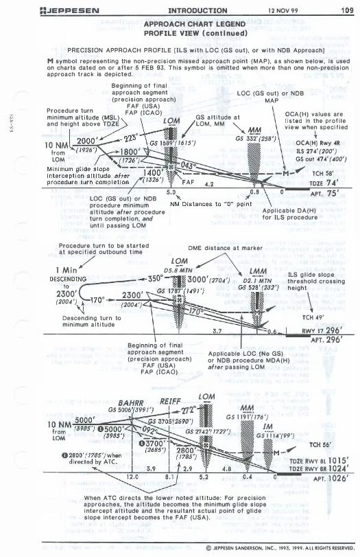
==.JEPPESEN INTRODUCTION
APPROACH CHART LEGEND PROFILE VIEW ( con t i nued)
1 2 NOV 99
PRECISION APPROACH PROFILE fiLS w i t h LOC (GS out), or w i t h NOB Approach]
1 0 9
M symbol representing the non-preci s i on missed approach point (MAP), a s shown below, is used on charts dated on or aiter 5 FEB 93. This symbol is omitted when more than one non-preci s i on approach trac k is depicted.
Beginning of f inal approach segment (precision approach)
LOC (GS out) or NOB MAP
FAF (USA) Procedure turn FAP (ICAO) minimum a l t i tude7,(MSL) L OM GS a l t i t ude at and height above TOZE -- /LOM , MM "" 1:!�
, GS 332' 1 0 NML-=��� 16 15') from LOM
OCA(H) values are l i sted in the prof i le v iew when speci f ied
\ OCA(H) Rwy .4R ILS 27.4' (200') GS out .47.4' (400') "���;:;::::;���Jt.;--M-....... TCH 58'
.4.2 TDZE 74 '
APT. 75 ' LaC (GS out) or NOB procedure minimum a l t i tude after procedure turn complet ion, and unt i l passing LOM
Appl icable OA(H) for ILS procedure
Procedure turn to be started DME distance at marker at spec i f i ed outbound t ime
1 Min / D5��:rN � LMM DESCENDING=-_---- -- 350o -. 3000' (2704') D2.-'·MTN
to
C GS ri87�( 1491 ') GS 5�8'(2J2')
ILS g l ide slope threshold crossing
2300' 0 2300' _ �81 �� (2004') ... + 170 -- (2004') ""''''''_ �I�..,..... '\l 1700 -----i,Ml-
height\
Descending turn to � "§ minimum a l t i tude � �
Beginning of f inal approach segment (precis ion approach)
FAF (USA) FAP (ICAD)
Applicable LaC (No GS) or NOB procedure MOA(H) after passing LOM
LOM
MM GS 1 19i"7i 176 ')
TCH .49'
� 1M I Gs'j'ii "" (99 ') � I� TCH 56' - M-""""
, TDZE RWY 8L 1 0 1 5 '
When ATC d i rects the lower noted a l t i tude: For precision approaches, the a l t i tude becomes the minimum g l ide s lope i ntercept a l t i tude and the resul tant actual point of g l ide s lope intercept becomes the FAF (USA).
TOZE RWY 8R 1 024 '
o APT. 1 026'
© JEPPESEN SANDERSON, INC., 1993, 1999. A L L RIGHTS RESERVED.
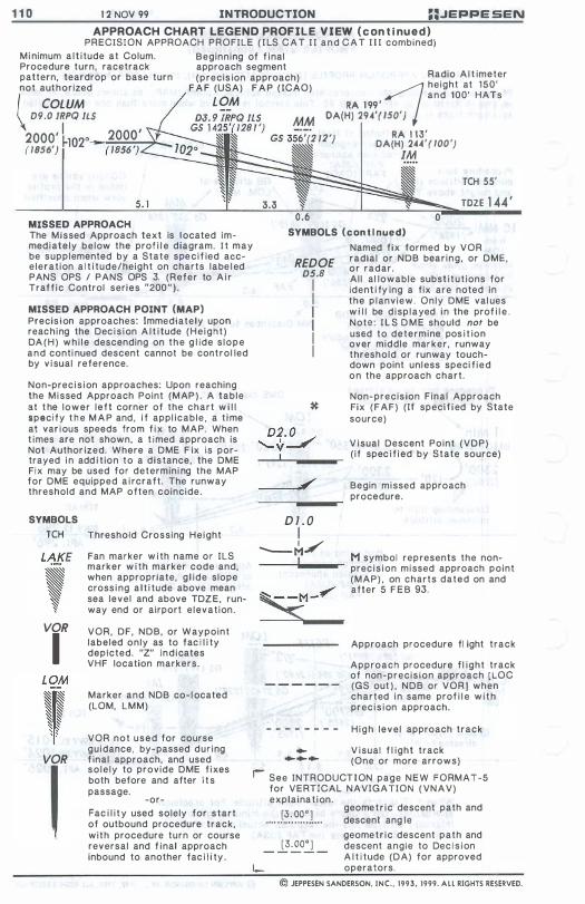
1 1 0 1 2 NOV 99 INTRODUCTION ::JEPPE SEN
APPROACH CHART LEGEND PROFILE VIEW ( c on t i nued) PRECISION APPROACH PROFILE ( I LS C A T I I a n d C A T I I I combined)
M i nimum a l t i tude at Colum. Procedure turn, racetrack pattern, teardrop or base turn not authorized
Beginning of f inal approach segment (precis ion approach) Radio A l t imeter ;;;; height at 150'
and 100' HATs RA 1 99 '
F A F (USA) F A P ( ICAO)
£ OM I COLUM \ D9.0 IRPQ ILS
2000' I ( /856') r1
. 1 MISSED APPROACH The Missed Approach text is located immediately below the prof i l e diagram. I t may be supplemented by a State spec i f ied accelerat ion a l t i tude/height on charts labe l ed PANS OPS / PANS OPS 3. (Refer to A i r Traff i c Control series "200 " ) .
MISSED APPROACH POINT (MAP) Precis i on approaches: immediately upon reaching the Dec i s i on A l t i tude (He ight ) DA ( H ) wh i le descending on the g l ide s lope and conti nued descent cannot be control led by v i sual reference.
Non-prec i s i on approaches: Upon reaching the M i ssed Approach Point (MAP ) . A table at t he lower left corner of the chart w i l l specify t h e M A P and , i f appl icable, a t ime at var ious speeds from f i x to MAP. When t imes are not shown, a t imed approach is Not Author ized. Where a DME F ix is portrayed i n add i t ion to a distance, the DME Fix may be used for determini ng the MAP for DME equipped a i rcraft . The runway threshold and MAP often coincide.
SYMBOLS
TCH
VOR
I
VOR
,
Threshold Crossing Height
Fan marker w i th name or ILS marker w i th marker code and, when appropriate, g l ide slope cross i ng a l t i tude above mean sea level and above TDZE, runway end or airport e levat ion.
VOR, DF, NDB, or Waypoint labeled only as to fac i l i ty depicted. "Z" ind icates VHF location markers.
Marker and NDB co- l ocated (LOM, LMM)
VOR not used for course guidance, by-passed dur ing f inal approach, and used sole ly to provide DME f ixes both before and after i t s passage.
-or-Fac i l i t y used solely for start of outbound procedure track, with procedure turn or course reversal and f inal approach inbound to another fac i l i ty .
OA(H) 294'( /50')
, RA 1 13' /2 ) OA{H) 244'( 100') 1M
TCH 55'
TOZE 1 44 '
SYMBOLS (con t i nued)
REDOE D5.8
I I I I I I
D2, 0 � """'-- V-
---"
D l . 0 I
-M/ I
Named f ix formed by VOR radial or NOB bear ing, or DME, or radar. Al l al lowable subst i tut ions for ident i fy ing a fix are noted in the p lanview. Only DME val ues w i l l be d isp layed in the prof i l e . Note: I L S D M E should nof be used to determine pos i t ion over middle marker , runway threshold or runway touchdown pOint unless speci f ied on the approach chart .
Non-precis ion F inal Approach Fix (FAF) (If specif i ed by State source)
V isual Descent Point (VDP) ( i f spec i f i ed by State source)
Begin missed approach procedure.
M symbol represents the nonprec i s i on missed approach point (MAP) , on charts dated on and after 5 F E B 93.
Approach procedure fl ight track
Approach procedure f l ight track of non-precis ion approach [LOC
- - - - - - (GS out ) , NDB or VORl when charted i n same prof i l e w i t h prec i s i on approach.
- - - - - - - - H i g h level approach track
.. V isual f l ight track ...... (One or more arrows)
I' See INTRODUCT I ON page NEW FORMAT-5 for VERTICAL NAVIGATION ( VNAV) explaina t i on.
geomet r ic descent path and .... J�:.??:).... descent ang le
geometr ic descent path and
_ £3�0.1 _ descent angle to Dec i s i on A l t i tude (DA) for approved
1- operators.
tel JEPPESEN SANDERSON, INC. , 1993, 1999. ALL RIGHTS RESERVED.
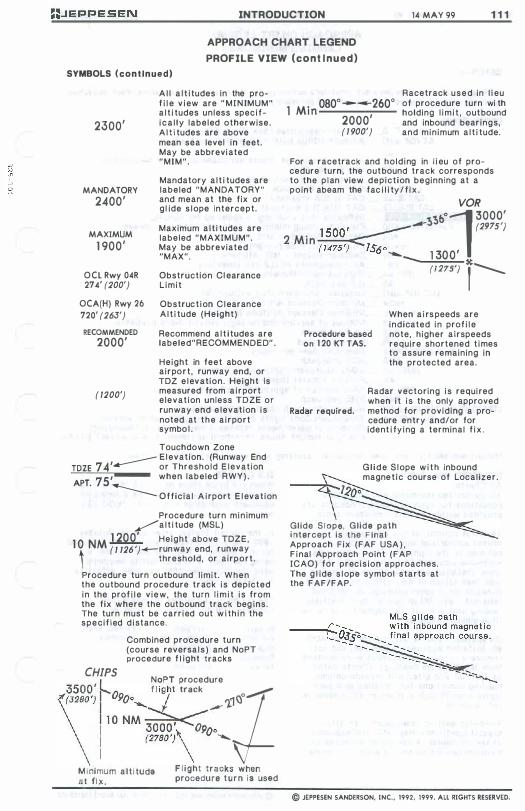
INTRODUCTION 14 MAY 99 1 1 1
APPROACH CHART LEGEND
PROFILE VIEW (cont i nued)
SYMBOLS (continued)
2300'
MANDATORY 2400'
MAXIMUM 1 900'
OCL Rwy 04R 274' (200')
OCA(H) Rwy 26 720' (263')
RECOMMENDED
2000'
( /200')
A l l a l t i tudes in the prof i l e v i ew are " MI N IMUM" a l t i tudes unless spec i f i c a l l y labeled otherwise. A l t i tudes are above mean sea level in feet. May be abbreviated "MIM".
Mandatory a l t i tudes are labeled "MANDATORY" and mean at the fix or g l ide s lope intercept.
Maximum alt i tudes are labeled "MAXIMUM". May be abbreviated "MAX".
Obstruction Cl earance L imit
Obstruct ion C l earance A l t i tude (Height)
Recommend a l t i tudes are labeled"RECOMMENDED" .
Height in feet above airport , runway end, or TDZ e levation. Height is measured from a i rport elevation unless TDZE or runway end e levation is noted at the a i rport symbo l .
Touchdown Zone __ E l evation. (Runway End TOZE 74' or Threshold E levation
APT. 75' when labeled RWY) .
------ Offic ia l A i rport E l evat ion
Procedure turn min imum �a l t i tude (MSL)
1 0 NM 1 200' Height above TDZE, i ( 1 126 ')_rUnway end, runway threshold, or airport.
Procedure turn outbound l imit . When the outbound procedure track is depicted in the prof i l e v iew, the turn l i m i t is from the fix where the outbound track beg ins. The turn must be carr ied out w i th i n the specif ied d istance.
Combined procedure turn (course reversa ls ) and NoPT procedure f l ight tracks
CHIPS I NoPT procedure \����; t0900_ m/, ", .. -'1 1 1 0 NM �
o ! (2780 ')\ '0 .......
M i nimum alt i tude F l ight tracks when at f ix . procedure t u r n I s used
. 080°----260° 1 M i n 2000'
Racetrack used in l i eu of procedure turn wi th holding l i m i t , outbound and inbound bear ings, and minimum a l t i tude. ( / 900')
For a racetrack and holding in l i eu of procedure turn, the outbound track corresponds to the plan view depiction beginning at a point abeam the fac i l i ty / f i x .
VOR ��bOJ 3000'
. 1 500' _____ - (2975')
2 M l n �� ( 1475 ) 156 ° .......
__ 1 30 0 ' � (1275') , ____
When a i rs peeds are indicated in prof i l e
Procedure based note, higher a irspeeds on 1 20 KT lAS. require shortened t imes
to assure remaining in the protected area.
Radar vectoring is required when i t is the only approved
Radar required. method for providing a procedure entry and/or for ident i fy ing a terminal f i x .
G l i d e S lope w i t h inbound magnet ic course of Local izer.
Glide S l ope, Glide path i ntercept is the F inal Approach Fix (FAF USA ) . F inal Approach Point (FAP ICAO) for precis ion approaches. The g l ide s lope symbol starts at the FAF/FAP.
© JEPPESEN SANDERSON, INC., 1992, 1999. All RIGHTS RESERVED.
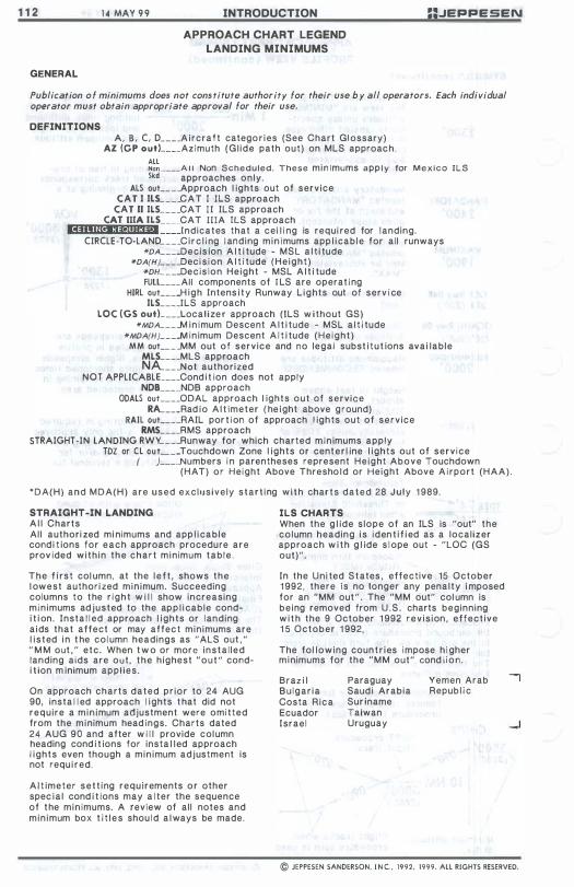
1 1 2
GENERAL
1 4 MAY 9 9 INTRODUCTION
APPROACH CHART LEGEND LANDING MINIMUMS
==JEPPESEN
Publication o f minimums does not constitute authority for their use b y all operators. Each individual operator must obtain appropriate approval for their use.
DEFINITIONS A, S , C, D ____ A ircraft catego r i es (See Chart Gl ossary)
AI (CP outL ___ Azimuth (Gl ide path out) on MLS approach. ALL Non ____ A I I Non Scheduled. These min imums app l y for M e x i c o ILS Skd approaches only .
ALS ouL _ _ _ Approach l ights out of service CAT I ILS _ _ _ _ CAT I lLS approach
CAT II ILS _ _ _ _ CAT I I ILS approach CAT iliA ILS CAT llIA ILS approach
.4,.lIn"'1_1I10H Indicates that a cei l i ng is requi red for landing. CIRCLE-TO-LAND _ _ _ _ C i r c l i ng l anding min imums app l i cable for al l runways
*DA ___ .Decis ion A l t i tude - MSL a l t i tude *DA(H} _ _ _ _ Deci s i on A l t i tude (He ight) *DH _ _ _ .Decis ion Height - MSL A l t i tude
FUlL ___ AII components of I LS are operat i ng HIRL ouL _ _ ..H igh Intens i t y Runway L ights out of serv i ce
ILS ____ ILS approach LOC (CS outL ___ Local ize r approach (ILS w ithout GS)
*MDA _ _ _ _ M in imum Descent A l t i tude - MSL a l t i tude *MDA(H} _ _ _ jA in imum Descent A l t i tude (Height)
M M ouL _ _ _ MM out of service and no legal subst i tut ions ava i lable MLS ____ MLS approach NA _ _ _ Not authorized
NOT APPLlCABLE.. ___ Cond i t ion does not apply NDB ___ ..NDB approach
ODALS ouL _ _ _ ODAL approach l ights out of service RA... ___ Rad io A l t imeter ( he ight above ground)
RAIL ouL ___ RAIL por t ion of approach l ights out of service RMS ____ RMS approach
STRAIGHT-IN LANDING RWY _ _ _ _ Runway for which charted min imums apply TDZ or CL oUL _ _ _ Touchdown Zone l ights or center l ine l ights out of serv ice
( ) ___ ..Numbers i n parentheses represent Height Above Touchdown (HAT) or Height Above Thresho l d or Height Above A i rport (HAA) .
"DA(H) and MDA(H) are used exclusively start ing with charts dated 28 July 1 989.
STRAIGHT-IN LANDING A l l Charts All authori zed mi nimums and app l i cable cond i t ions for each approach procedure are prov ided with in the chart minimum table .
The f i rst col umn, at the l e f t , shows the l owest authori zed min imum. Succeeding columns to the r ight w i l l show increasing minimums adjusted to the app l i cable condi t i on. Insta l l ed approach l ights or landing a ids that affect or may affect min imums are l i sted i n t he col umn headings as "ALS out , " " M M out , " etc. When t w o or more insta l led landing aids are out , the h ighest "out" condi t ion m inimum appl ies.
On approach charts dated pr ior to 24 AUG 90, insta l l ed approach l ights t hat did not require a min imum adjustment were omitted from the minimum head ings, Charts dated 24 AUG 90 and after w i l l provide column heading cond i t ions for insta l led approach l ights even though a min imum adjustment is not requ i red.
A l t imeter sett ing requirements or other spec ia l cond i t ions may a l ter the sequence of the min imums, A review of all notes and min imum box t i t l e s shou l d a l ways be made.
ILS CHARTS When the g l ide s lope of an ILS is "out" the column heading i s iden t i f i ed as a localizer approach w i th g l ide s l ope out - "LOC (GS out)".
In the Uni ted States , effective 15 October 1 992, there is no longer any penalty i mposed for an "MM out" . The "MM out" col umn is being removed from U.S . charts beginning w i t h the 9 October 1 992 rev is ion , effect ive 1 5 October 1 992,
The fol lowing countr ies I mpose hi gher minimums for the "MM out" cond i ion .
Braz i l Bu lgar ia Costa Rica Ecuador Israel
Paraguay Saud i Arabia Sur iname Taiwan Uruguay
Yemen Arab Repub l i c
© JEPPESEN SANDERSON. I N C . • 1992. 1999. ALL RIGHTS RESERVED.

JEPPESEN INTRODUCTION 9 OCT 92 1 1 3
APPROACH CHART LEGEND LANDING MINIMUMS (con t i nued)
USA FORMAT - Pr ior to 1 5 October 1 992 E f fect ive da te. STRAIGHT-IN LANDING RWY 36L CIRCLE-TO-LAND
ILS LOC (GS out) DA(H) 2 1 2' (200') DA(H) 262'(250') MDA(H) 400' (388')
FULL TO' or CL out ALS out MM out ALS out x
Kts I--MDA(H)_ � 90
560' (533')- 1 I--,!. RVR 24 0r Y2 RVR 24 or Y2 RVR 50 or 1 120
RVR 1 8 RVR 24 RVR 40 C or Y2 or Y2 or % 140 560 '(533')- 1 Y2 '-D RVR 400r % RVR 400r % RVR 60 or lY4 165 580' (553')-2
r- USA FORMAT '" Effect ive 15 October 1 99 2 and a l l succ"ed lng rev is ions -STRAIGHT-IN LANDING RWY 36L CIRCLE-TO-LAND
ILS LOC (GS out) DA(H) 2 1 2 ' (200') MDA(H) 400' (388')
FULL TDZ or CL out ALS out ALS out Kts �MDA(H) ___
� 90 560' (533')- 1 I--
� RVR 24 or Y2 RVR 50 or 1 120
C RVR 1 8 or Y2 RVR 24 or Y2 RVR 400r % 140 560 '(533')- 1 Y2 I-D RVR 400r % RVR 60 0rlY4 165 580' (553')- 2
WORLD-WIDE FORMAT STRAIGHT-IN LANDING RWY 36L CIRCLE-TO-LAND
ILS LOC (GS out) DA(H) 2 1 2 ' (200') MDA(H) 400' (388')
FULL TDZ or CL out ALS out ALS out ax
Kts I--MDA(H) � 100
560 '(533') - 1600m RVR 720m RVR 1500m -,!. 135
RVR 550m RVR 720m VIS 800m VIS 1600m C VIS 800m VIS 800m 1200m 180 630'(603') -2800m ,.... D 1200m RVR 1800m
205 730' (703') -3600m VIS 2000m
SIDESTEP INOPERATIVE COMPONENTS For a runway identified as sidestep, such as SIDESTEP RWY 24L:
Inoperative l ight components shown in Rwy 24L column are those for the l i ghts instal led on Rwy 24L, not the I ights for Rwy 24R.
CIRCLE-TO- LAND Starting with charts dated July 28, 1 989, maximum aircraft speeds for circl ing are shown in l ieu of Aircraft Approach Categories. The maximum i ndicated a i rspeeds are shown in knots (k i lometers per hour on Metric Edit ion charts) .
U.S. STANDARD FOR TERMINAL INSTRUMENT APPROACH PROCEDURES
(TERPS)
CIRCLE-TO-LAND
��:�MDA(H) 90
560' (533')- 1 f--120
140 560' (533')- 1 Y2
165 580' (553')-2
Known deviations to the above speeds are charted. For the few countries that have not published maximum circl ing speeds, aircraft approach categories A,B,C and D will continue to be shown. Aircraft Approach Categories in the straightin minimum column can be read across the chart from left to r ight for referencing the ci rcle-to-Iand information. The fact that straight-in-mlnimums are not
NEW INTERNATIONAL CIVIL AVIATION ORGANIZATION
( ICAO) FLIGHT PROCEDURES
CIRCLE-TO- LAND
�:I--MDA(H) � 560 ' (533') - 1600m
135
180 630' (603') -2800m
205 730'(703') -3600m
published does not prec l ude the p i lot from landing straight-in, using published circ l ing minimums, i f he has the straight-in runway in sight in sufficient time to make a normal approach for landing. Under isuch condit ions, and when Air Traffic Control has cleared him for landing on that runway, he is not expected to circle even though straight-in minimums are not publ ished. I f he desires to ci rcle, he should advise ATC.
© JEPPESEN SANDERSON, INC., 1992. ALL RIGHTS RESERVED
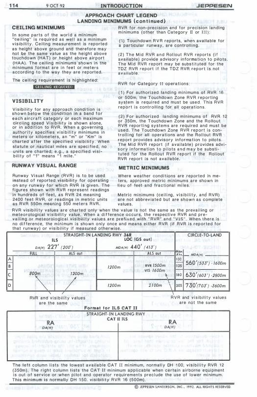
1 1 4 9 OCT 92 INTRODUCTION JEPPESEN
� B I-C
I-D
APPROACH CHART LEGEND LANDING MINIMUMS (con t i nued)
CEILING MINIMUMS
In some parts of the wor l d a m i n imum "ce i l i ng" is required as we l l as a min imum v i s i b i l i ty . Cei l ing measurement is reported as height above ground and therefore may not be the same value as the height above touchdown (HAT) or height above airport (HAA). The cei l ing minimums shown in the minimums format are i n feet or meters according to the way they are reported.
The cei l ing requirement is h igh l ighted:
··"'Ma:'."c'.-
VISIBILITY
Vis ibi l i t y for any approach condi t ion is shown be low the condi t ion i n a band for each a i rcraft category or each maximum circl ing speed V i s i b i l i t y is shown a l one, or in add i t ion to RVR. When a governing author i ty specifies v i s i b i l i t y minimums in meters or k i l ometers, an "m" or "Km" is charted after the specif ied v is ib i l i t y . When statute or nautical miles are spec i f ied, no units are charted; e , g . , a speci f ied v is ib i l i ty of "1" means "1 mile ."
RUNWA Y VISUAL RANGE
Runway Visua l Range (RVR) is to be used instead of reported visibi l i ty for operating on any runway for which RVR is g iven. The f igures shown with RVR represent readings in hundreds of feet, as RVR 24 meaning 2400 feet RVR, or readings i n metric units as RVR 550m meaning 550 meters RVR.
RVR for non-precision and for precision landing minimums (other than Category II or I l l ) : ( 1 ) Touchdown R V R reports, when avai lable for a particular runway, are control l ing .
( 2 ) The Mid RVR and Rol lout RVR reports ( i f available) provicJe advisory information to pilots. The Mid RVR report may be subst i tuted for the TDZ RVR report i f the TDZ RVR report is not avai lable .
RVR for Category I I operat ions:
( 1 ) For authorized land ing min imums of RVR 1 6 or 500m, the Touchdown Zone RVR reporting system is requi red and must be used. This RVR report is contro l l ing for al l operat ions.
( 2 ) For authori zed landing minimums of RVR 1 2 or 350m, the Touchdown Zone and the Rol lout RVR report i ng systems are required and must be used. The Touchdown Zone RVR report is control l i ng for all operations and the Rol lout RVR report provides advisory informat ion to pilots. The Mid RVR report (if avai lable) provides adv i s o r y i nformat ion t o pi lots a n d m a y b e substituted for the Rol lout RVR report if the Rol lout RVR report is not avai lable.
METRIC MINIMUMS
Where weather condi t ions are reported in meters, approved metric minimums are shown in l ieu of feet and fractional mi les.
Metr ic min imums (ce i l i ng , v i s i b i l i t y , and RVR) are not abbrev iated but are shown as complete values.
RVR v is ib i l i ty values are charted only when the va lue I s not the same as the preva i l ing or meteorological v i s i b i l i t y value. When a d i f ference occurs, the respect ive RVR and preva i l ing or meteorological v is ibi l i ty values are prefixed with " RVR" and "VIS". When there is no d i f ference, the min imum is shown only once and means ei ther RVR (if RVR is reported for that runway) or v i s i b i l i t y if measured otherwise
STRAIGHT· IN LANDING RWY 36R
OA(H) FULL
80\ ILS
227' (200') ALS out
Jom
"-RVR and v i s i b i l i t y v a lues
are the same
LOC (GS out)
MOA(H) 440' (413') ALS out
1200m RVR 1500m VIS 1600m �
1200m 1100m
Format f o r ILS CAT II
STRAIGHT· IN LANDING RWY
RA CAT II ILS
CIRCLE· TO·LAND
ax KI, f- MOA(H} � 560 '(533') . 1600m 135
180 630 '(603 ') ·2800m
\ 205 730'(703') ·3600m \ RVR and v is ibi l i t y values
are not the same
RA DA(H) DA(H)
The left column l i sts the lowest avai lab le CAT I I mi nimum, normal l y DH 1 00, v is ibi l i t y RVR 1 2 (350m) . The r ight column l ists the CAT I I minimum appl icable when certain a irborne equipment is out of service or when pi lot and operator requirements prec l ude the use of lower mi nimum.
This minimum is normally DH 1 50, v is ibi l i t y RVR 16 (500m).
© JEPPESEN SANDERSON, INC., 1992. AlL RIGHTS RESERVED.
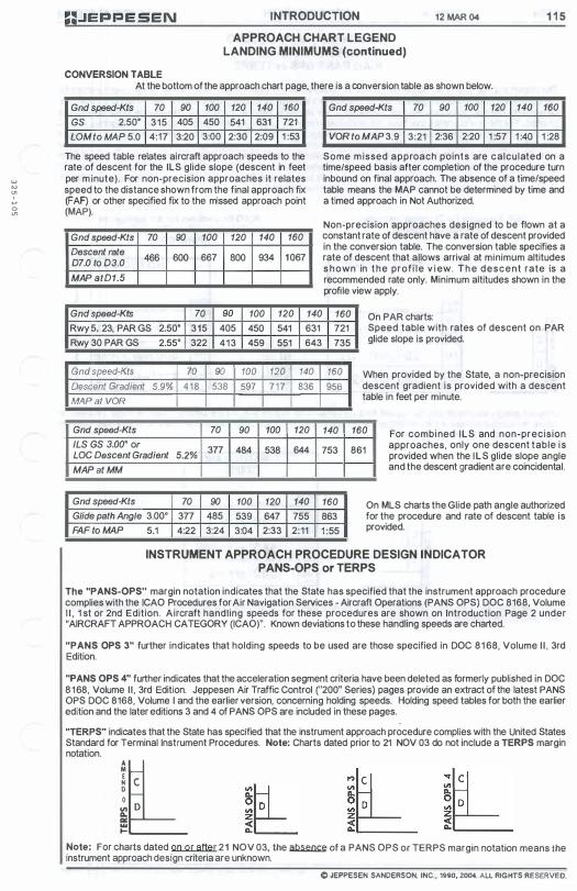
w w '" , .... o "'
;;.JEPPESEN INTRODUCTION 12 MAR 04 1 1 5
APPROACH CHART LEGEND LANDING MINIMUMS (continued)
CONVERSION TABLE At the bottom of the approach chart page, there is a conversion table as shown below.
Gnd speed-Kts 70 90 100 120 140 160
GS 2.50· 315 405 450 541 631 721
LaM to MAP 5.0 4:17 3:20 3:00 2:30 2:09 1 :53
The speed table relates aircraft approach speeds to the rate of descent for the ILS glide slope (descent in feet per m inute). For non-precision approaches it relates speed to the distance shown from the final approach fix (FAF) or other specified fix to the missed approach point (MAP).
Gnd speed-Kts 70 90 100 120 140 160
Descent rate 466 600 667 800 934 1067
07.0 to 03.0
MAP atD1.5
Gnd speed-Kts 70 90 100 120 140 160
VOR to MAP 3.9 3:21 2:36 2:20 1 :57 1 :40 1 :28
Some m issed approach points are calculated on a time/speed basis after completion of the procedure turn inbound on final approach. The absence of a time/speed table means the MAP cannot be determined by time and a timed approach in Not Authorized.
Non-precision approaches designed to be flown at a constant rate of descent have a rate of descent provided in the conversion table. The conversion table specifies a rate of descent that allows arrival at minimum altitudes s hown in the profi le v i ew. T h e descent rate is a recommended rate only. Minimum altitudes shown in the profile view apply.
Gnd speed-Kts 70 90 100 120 140 160 On PAR charts: Rwy 5, 23, PAR GS 2.50· 315 405 450 541
Rwy 30 PAR GS 2.55· 322 413 459 551
Gnd speed-Kts 70 90 100 120 Descent Gradient 5.9% 418 538 597 7 17 MAP a/ VOR
Gnd speed-Kts 70 90 100
/LS GS 3.00· or 377 484 538
LaC Descent Gradient 5.2%
MAP at MM
Gnd speed-Kts 70 90 100 120
Glide path Angle 3.00· 377 485 539 647
FAF to MAP 5.1 4:22 3:24 3:04 2:33
631
643
140 836
120
644
140
755
2:11
721
735
160 956
140
753
160
863
1 :55
Speed table with rates of descent on PAR glide slope is provided.
When provided by the State, a non-precision descent gradient is provided with a descent table in feet per minute.
160 For combined ILS and non-precision approaches, only one descent table is provided when the ILS glide slope angle and the descent gradient are coincidental.
861
On MLS charts the Glide path angle authorized for the procedure and rate of descent table is provided.
INSTRUMENT APPROACH PROCEDURE DESIGN INDICATOR PANS-OPS or TERPS
The "PANS-OPS" margin notation indicates that the State has specified that the instrument approach procedure complies with the ICAO Procedures for Air Navigation Services - Aircraft Operations (PANS OPS) DOC 8168, Volume I I , 1 st or 2nd Edition. Aircraft handling speeds for these procedures are shown on Introduction Page 2 under "AIRCRAFT APPROACH CATEGORY (ICAO)". Known deviations to these handling speeds are charted.
"PANS OPS 3" further indicates that holding speeds to be used are those specified in DOC 81 68, Volume I I , 3rd Edition.
"PANS OPS 4" further indicates that the acceleration segment criteria have been deleted as formerly published in DOC 8168, Volume II , 3rd Edition. Jeppesen Air Traffic Control ("200" Series) pages provide an extract of the latest PANS OPS DOC 8168, Volume I and the earlier version, concerning holding speeds. Holding speed tables for both the earlier edition and the later editions 3 and 4 of PANS OPS are included in these pages.
"TERPS" indicates that the State has specified that the instrument approach procedure complies with the United States Standard for Terminal Instrument Procedures. Note: Charts dated prior to 21 NOV 03 do not include a TERPS margin notation. 'l en 0 Do. '" ... ....
Note: For charts dated on or after 21 NOV 03, the � of a PANS DPS or TERPS margin notation means the instrument approach design criteria are unknown.
C JEPPESEN SANDERSON, INC., '.90, 2004. All RIGHTS RESERVED.

I I vii 12 MAR 04 IN I RODUCTION
APPROACH CHART LEGEND
CIRCLE-TO-LAND
ICAO PANS OPS or TERPS
�:JEPPE SEN
The Instrument Approach Procedure margin also indicates whether PANS OPS or TERPS criteria have been applied for the construction of the circling area. Maximum aircraft speeds for circling are shown in l ieu of ai rcraft approach categories. The maximum indicated airspeeds (lAS) are shown in knots and any known deviations to the speeds are charted. For the few countries that have not published maximum circling speeds, aircraft approach categories A, B, C and D will continue to be shown, Aircraft approach categories in the straight-in column can be read across the chart from left to right for referencing the circle-to-Iand information. The fact that straight-in minimums are not published does not preclude the pilot from landing straight-in, using published circling minimums, if the straight-in runway is in sight with sufficient time to make a normal approach for landing. Under such conditions, and when Air Traffic Control has provided clearance to land on that runway, the pilot is not expected to circle even though straight-in minimums are not published. However, if a circling maneuver is desired, the pilot should advise ATC.
U.S. Standard for Terminal Instrument Procedures (TERPS)
CIRCLE· TO-LAND
Max Kt, � MDA(H)
;l '" D
� III I-
90
560 '(553 ') - 1 -1 20
140 560'(553') - l Y2
105 5 8 0 '(573 ') - 2
ICAO Procedures for Air Navigation Services - Aircraft Operations
(PANS OPS)
CIRCLE· TO-LAND
Max Kh I-- MDA(H) 1 00
560 '(553 '). 1600m f--135 ISO 630 '(603')-2800m
205 730 '(703 ')-3600m
D ifferent design standards may be applied for the approach procedure than for the circling areas. In those exceptional cases, an additional label in the heading of the circling minimums box will indicate the criteria which have been applied for the construction of the circling area.
CIRCLE-TO-LAND (TERPS)
Max Kts �MDA(H)
� 560 '(55J') - 1 120
140 560 '(553 ') - l Y2
165 5 8 0 '(573 ') - 2
In this example, the instrument approach procedure complies with ICAO PANS OPS criteria, whereas the circling areas are constructed based on TERPS criteria.
© JEPPESEN SANDERSON. INC., 1990. 2004. ALL RIGHTS RESERVED.
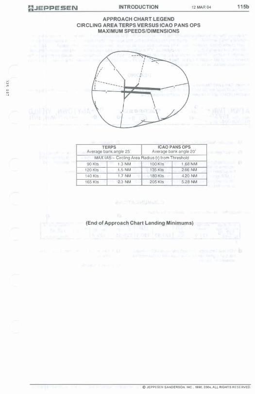
INTRODUCTION 1 2 MAR 04
APPROACH CHART LEGEND CIRCLING AREA TERPS VERSUS ICAO PANS OPS
MAXIMUM SPEEDS/DIMENSIONS
TERPS ICAO PANS OPS Average bank angle 25' Average bank angle 20'
MAX lAS - Circling Area Radius (r) from Threshold
90 Kts 1 .3 NM 1 00 Kts 1 .68 N M
1 20 Kts 1 .5 NM 1 35 Kts 2.66 NM
1 40 Kts 1 .7 NM 1 80 Kts 4.20 NM
1 65 Kts 2.3 NM 205 Kts 5.28 NM
(End of Approach Chart Landing Minimums)
1 1 5b
© JEPPESEN SANDERSON. INC .. ,99(). �OO4. ALL RIGHTS RESERVED.

1 1 6 1 2 MAR 04 INTRODUCTION
APPROACH CHART LEGEND AIRPORT CHART FORMAT
==.JEPPE SEN
The airport chart is typically printed o n the reverse side o f the first approach chart i n the series. At many airports, especially large terminals, the airport chart will precede the first approach chart and contain an enlarged diagram. Airport charts depict communications frequencies as well as runway, taxiway and ramp information. Additionally, approach and runway lighting, declared distances, IFR and obstacle departure procedures, and take-off and alternate minimums are shown. In the example of a chart with an enlarged diagram, this information will usually be printed on the reverse side of the ai rport diagram. Separate charts may be included that depict detailed ramp areas and parking positions as well as low visibility taxi routes.
HEADING
Airport, Ramp and Taxiway charts At the top of page are the location and airport names, the airport's elevation and latitude and longitude, the Jeppesen NavData (ICAO) and lATA identifiers, and the revision date.
ATWN!TWN� Apf Elev 1 57 5 ' - � N40 00.0 W 1 04 5 1 .0 """'---- -
0. ::JEPPESEN -.......... OATE QI).....-e
O--ANYTOWN" WORLD
o Jeppesen NavData (ICAO) and lATA identifiers.
o Airport elevation.
o Geogra p h i c latitude and l o n g i tu d e coordinates i n degrees, minutes, a n d tenths of minutes, representing the location of the airport reference point (ARP) when an ARP symbol is shown. On charts where the ARP is not shown, coordinates represent the airport location as provided by the controlling authority.
o . ANYTuWN, INTL
o Revison date.
o Index (page) number (same as approach chart when the a irport is printed on the reverse side of the first approach chart).
o Geographic location name.
o Airport name.
COMMUNICATIONS
Communications for departure are listed in order of normal use.
*ANYTOWN Ooparluro(Rj 1 26 . 55 1 25 . 5
o A n a s t e r i s k ( * ) i n d i cates p a rt-t i m e operation.
o Radar is available
© JEPPESEN SANDERSON, INC., 1990, 2004. ALL RIGHTS RESERVED.

� .. .c a w
JEPPESEN INTRODUCTION 1 1 JUL 97 1 1 7 APPROACH CHART LEGEND
AIRPORT PLAN VIEW
SYMBOLS
Physical feature symbols used on the a irport chart are i l l ustrated below.
- @
- GD 267"
=:::J (27W)
===::::J
II * II
Runway number is magnetic unless fo l lowed by T for t rue in the far north.
Runway number and (when known) magnetic d i rection, unless fol l owed by T for true in the far north .
Seaplane operat ing area , or water runway.
Paved runway
Unpaved runway
Pi erced steel p l anking (PSP)
Seaplane operating area or water runway. Dash l ines ind icate operating area.
Displaced threshold
Designated stop bar or designated holding posi t ion.
Category I I / I I I holding pos i t ion.
Approach l ights extending to d isp laced threshold
5 Unidi rectional Arrester Gear
===::::i
Bid i rectional Arrester Gear
Jet Barrier
C losed runway. Temporary c losed runways w i l l retain l ength and runway numbers.
Stopway or overrun
Area under construct ion
Runway shoulder (when read i l y noticeable)
No d i fferentiation between types of surface for ramps, taxiways, closed runways, c losed tax i ways, runway shoulders, and areas other than runways. Stopways and overruns are shown regardless of surface, w i t h the length, when known. Stopway and overrun l engths are not included in runway lengths.
ADDITIONAL INFORMATION
Runway end e levations are shown on the a irport d iagram if source is avai l able .
Approach l ights and beacons are the only l ig ht ing symbo l i zed on the ai rport d iag r am. Approach l ights are normal l y shown to scale in a recognizable form. For approach I ight symbols see page 1 2 1 .
A representat ive selection o f reference pOints known to Jeppesen is depicted. The elevation of reference pOints depicted is above mean sea level (MSL).
Lat itude and long i tude t icks at tenths of a minute interval are charted around most p lanview neatl ines.
X X X x X
o Lib. $ ARP
VOR <;)
- T - r
"{-
.' ..Tt ""'J .'
��-. ("�� ... t ... ) -'
f' '"
�
I • .. ��
Taxiway and apron
Permanent ly closed taxi way
Authori zed Landing Area
He l icopter landing pad
Ai rport Reference Point. Offrunway. Center of cross posit ioned at exact location.
Ai rport Reference Point. Located on runway center l ine. Arrow points to exact location.
RVR measuring site, may have ident ify ing letter or number.
A i rport/ Aerodrome/ Ident i f ication beacon.
On-airport navaid - VOR, NDB or LCTR ( l ocators, other than locators associated wi th ILS) . Depicted on charts dated on and after 5 FEB 93.
Rai l road
Pole l i ne
Lighted Pole
Road
B luff
Trees
Cone
Tee
Tetrahedron
Bui ld ings
Large bui Id ing
Foot 0 1000 2000 3000 4000 5000 " .' ',t , 'I' \ I " ',' '. ! I 'I' \' � ',' I',' Metors 0 500 1000 1500
Bar Sca l e
© JEPPESEN SANDERSON, INC . . 199 1 , 1997. All RIGHTS RESERVED.
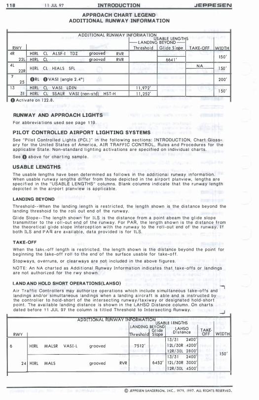
1 1 8 1 1 JUL 97 INTRODUCTION .JEPPESEN
RWY
APPROACH CHART LEGEND ADDITIONAL RUNWAY INFORMATION
ADDITIONAL RUNWAY INFORMATION USABLE LENGTHS
I-- LANDING BEYOND -Threshold Gl ide S lape TAKE-OFF WIDTH
4R HIRL CL ALSF-I TOZ grooved RVR 22L HIRL CL �grooved RVR 664 1 '
150'
4L HIRL CL NA 1 50 ' 22R HIALS SFL
7 ORL O VASI (angle 2 . 4°) 200' 25
1 3 HIRL CL VASI LO IN 1 1 ,972' 1 50' 31 HIRL CL SSALR VASI (non-std) HST-H 1 1 252'
O Act ivate on 1 22 .8 .
6
RUNWAY AND APPROACH LIGHTS
For abbrev iat ions used see page 1 1 9 .
PILOT CONTROLLED AIRPORT LIGHTING SYSTEMS
See "Pi lot Contro l led l ights (PCl)"' i n the fol lowing sections: I NTRODUCTION, Chart Glossary for the United States of Amer ica, A I R TRAFFIC CONTROL, Rules and Procedures for the appl icable State. Non-standard l i ght ing activat ions are specif i ed on i ndiv idual charts.
See 0 above for chart ing sampl e .
USABLE LENGTHS
The usable lengths have been determined as fol l ows in the add i t ional runway information. When usable runway lengths di ffer from those depicted i n t he a irport planview, lengths are spec i f i ed in the "USABLE lENGTHS" columns. B lank co lumns i nd icate that the runway length depicted in the ai rport planv iew i s appl i cable .
LANDING BEYOND
Threshold--When the land i ng length is restr i cted, the length shown is the d istance beyond the landing threshold to the rol l out end of the runway.
Gl ide Siope--The length shown for I lS is the d istance from a point abeam the g l ide s lope transmitter to t he r o l l -out end of the runway. For PAR, the length shown i s the di stance f rom the theoret ical g l Ide s lope intercept ion w i t h the runway to the rol l-out end of the runway. I f both IlS and P A R are avai l abl e, data prov ided i s for IlS.
TAKE-OFF
When the takt roff l ength is restr icted. the length shown is the d istance beyond the point for beginning the take-off ro l l to the end of the surface usable for take-off .
Stopways, overruns, or c lear ways are not inc luded i n the above f i gures.
NOTE: An NA charted as Add i t i onal Runway Information indicates that take-off s or landings are not authori zed for the rwy shown.
LAND AND HOLD SHORT OPERATlONS(LAHSO) "I A i r Traff ic Control lers may author ize operat ions which inc lude s i multaneous take-olfs and land ings and/or s imul taneous land ings when a land i ng a i rcraft is ab le and is instructed by the contro l ler to hold-short of the intersecting runway/taxiway or designated hold-short paint. The ava i lable landing d istance is shown i n the lAHSO Distance column. On charts dated before 1 1 JUl 97 the column is t i t l ed Threshold to Intersecting Runway.
ADDIIIONAL RUNWAY II i�OKMA IIUNUSABLE LENGTHS LANDING BEYOND LAHSO G l ide TAKE-RWY Threshold Slope D istance OFF
1 3/3 1 2400' HIRL MALSR VASI-L grooved 75 1 2 ' 1 2L/30R 4200'
1 2R/30L 2800' 1 3/3 1 2400'
24 HIRL MALS grooved RVR 6452' 1 2 L/30R 3000' 1 2R/30L 4500'
WIDTH
1 50 '
© JEPPESEN SANDERSON. INC.. 1979, 1997. ALL RIGHTS RESERVW.
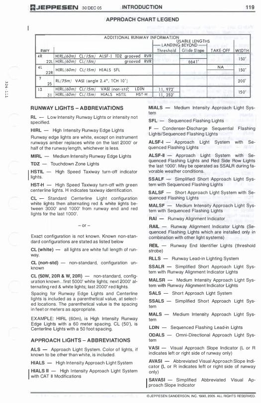
RJEPPESEN 30 DEC 05 INTRODUCTION 1 1 9
APPROACH CHART LEGEND
ADDITIONAL RUNWAY INFORMATION USABLE lENGTHS � lANDING BEYOND -
RWY Threshold G l i de S lope TAKE-OFF WIDTH 4R HIRl(60m) Cl( 15m} AlSF - I TDZ grooved RVR
1 50' 22l HIRl (60m) Cl( 15m) grooved RVR 664 1 ' 4 l HIRl (60m) Cli ISm) HIAlS SFl NA
1 50' 22R 7 Rl(7Sm) VASI (angle 2_40, TCH 1 0 ' ) 200'
25 1 3 HIRL (60m) Cli ISm) VASI (non-std) lOIN 1 1 , 972'
3 1 HIRL (60m) CLI ISm) HIAlS HSTll HST-H 1 1 252' 150'
RUNWAY LIGHTS - ABBREVIATIONS
RL - Low Intensity Runway Lights or intensity not specified. HIRL - High I ntensity Runway Edge Lights Runway edge lights are white, except on instrument runways amber replaces white on the last 2000' or half of the runway length, whichever is less. MIRL - Medium Intensity Runway Edge Lights TOZ - Touchdown Zone Lights
I HSTIL - High Speed Taxiway turn-off indicator lights. HST-H - High Speed Taxiway turn-off with green centerline lights. H indicates taxiway identification. CL - Standard Centerline Light configuration white lights then alternating red & white lights between 3000' and 1 000' from runway end and red lights for the last 1 000'.
- or -
Exact configuration is not known. Known non-standard configurations are stated as listed below CL (white) - all lights are white full length of runway. CL (non-std) - non-standard, configuration unknown CL (50W, 20R & W, 20R) - non-standard, configuration known .. .first 5000' white lights; next 2000' alternating red & white lights; last 2000' red lights. Spacing for Runway Edge Lights and Centerline lights is included as a parenthetical value, at selected locations. The parenthetical value is the spacing in feet or meters as appropriate.
EXAMPLE: HIRL (60m), is High Intensity Runway Edge Lights with a 60 meter spacing. CL (50'), is Centerline Lights with a 50 foot spacing.
APPROACH LIGHTS - ABBREVIATIONS
ALS - Approach Light System. Color of lights, if known to be other than white, is included. HIALS - High Intensity Approach Light System
I HIALS II - High I ntensity Approach Light System with CAT II Modifications
MIALS - Medium Intensity Approach Light System SFL - Sequenced Flashing Lights F - Condenser-Discharge Sequential Flashing Lights/Sequenced Flashing Lights ALSF-I - Approach Light System with Sequenced Flashing Lights ALSF-II - Approach Light System with Sequenced Flashing Lights and Red Side Row Lights the last 1 000'. May be operated as SSALR during favorable weather conditions. SSALF - Simplified Short Approach Light System with Sequenced Flashing Lights SALSF - Short Approach Light System with Sequenced Flashing Lights MALSF - Medium Intensity Approach Light System with Sequenced Flashing Lights RAI - Runway Alignment Indicator RAIL - Runway Alignment Indicator Lights (Sequenced Flashing Lights which are installed only in combination with other light systems) REIL - Runway End Identifier Lights (threshold strobe) RLLS - Runway Lead-in Lighting System SSALR - Simplified Short Approach Light System with Runway Alignment Indicator Lights MALSR - Medium IntenSity Approach Light System with Runway Alignment Indicator Lights SALS - Short Approach Light System SSALS - Simplified Short Approach Light System MALS - Medium IntenSity Approach Light System LOIN - Sequenced Flashing Lead-in Lights OOALS - Omni-Directional Approach Light System VASI - Visual Approach Slope Indicator (L or R indicates left or right side of runway only) AVASI - Abbreviated Visual Approach Slope Indicator (l or R indicates left or right side of runway only)
I SAVAS I - Simplified Abbreviated Visual Approach Slope Indicator
©JEPPESEN SANDERSON, INC. 1990, 2005. ALL RIGHTS RESERVED.

1 20 INTRODUCTION
APPROACH CHART LEGEND
VASI (3 bar) - Visual Approach Slope Indicator for high cockpit aircraft (L or R indicates left or right side of runway only). T-VASI - Tee Visual Approach Slope Indicator. AT-VASI - Abbreviated Tee Visual Approach Slope Indicator (L or R indicates left or right side of runway only). VASI (non-sId) - Visual Approach Slope Indicator when known to be non-standard.
VASI - VASI/AVASI/NON-STD angels are shown when known to be less than 2.5° or more than 3.00 • T-VASI/AT-VASI angles are shown at all times. VASI (3 bar) descent angles are shown when other than upwind angle 3.25° , downwind angle 3.00° .
I
APAPI - Abbreviated Precision Approach Path I ndicator (L or R indicates left or right side of the runway only) PAPI - Precision Approach Path Indicator (L or R indicates left or right side of runway only).
I PASI - Passive Approach Slope I ndicator PLASI - Pulsating Visual Approach Slope Indicator, normally a single light unit projecting two colors. (L or R indicates left or right side of runway only). TRev - Tri-Color Visual Approach Slope Indicator, normally a single light unit projecting three colors. (L or R indicates left or right side of runway only). TCH - Threshold Crossing Height. Height of the effective visual glide path over the threshold. MEHT - Minimum Eye Height over Threshold. Lowest height over the threshold of the visual on glide path indication. M EHT or TCH is shown (when known) when less than 60' for the upwind bar of a VASI (3 bar) system or less than 25' for all other systems including PAP! .
30 DEC 05 nJEPPESEN
© JEPPESEN SANDERSON. INC. 1990. 2005. ALL RIGHTS RESERVED.
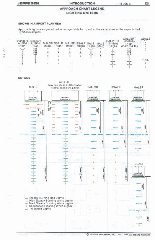
w OJ ". ,... ::;
JEPPESEN INTRODUCTION
APPROACH CHART LEGEND
LIGHTING SYSTEMS
SHOWN IN AIRPORT PLANVIEW
13 JUN 97 1 21
Approach l ights are symbolized in recognizable form, and at the same scale as the airport chart. Typical examples:
Standard Standard ALSF-I ALSF- I I MALSR SSALR MALSF SSALF (H igh) (High) (Med) (H igh) (Med) (H igh)
-
- -
DETAILS
ALSF- I I ALSF-I May operate as a SSALR when
weather conditions permit.
::::: l·�.f ..... T-I
I LANblNG
THRESHOLD It················· .. ·· . . ·
I ... ..... . ..
�f"'"
... � ... ��::. • .. , . , • .. . .. • ..... • ... .. • .....
� ..... · ..... • ..... • ..... • ..... � · .....
• 0
.. ... g •
..... ;: • ..... •
••• Steady Burning Red Lights • • • High Steady Burning White Lights ••• Med. Steady Burning White Lights
Sequenced Flashing White Lights ... Threshold Lights
I f
!
CALVERT SALS MALS (British) (High) (Med) (H igh)
- -
-
-
MALSR SSALR
:::::�t
..... . .. .. . ... .
._.
, ,
I f
�
CALVERT GDALS (British) (H i�h)
(CAT I & 1 1 1 )
i l!
!
RAIL
-
MALSF
.. ... ..... . .... . •
. .... •
. .... •
SSALF
:::::�I
..... ..... •
C JEPPESEN SANO<RSON, INC .. 1983, 1997. ALL RIGHTS RESERVED.
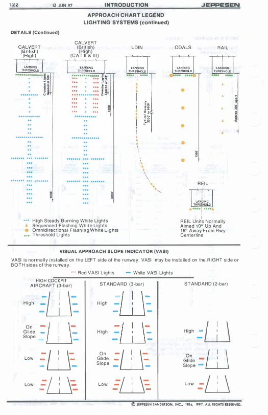
13 JUN 91 I NTRODUCTION
APPROACH CHART LEGEND
LIGHTING SYSTEMS (continued)
DETAILS (Conllnued)
·······:······ �i � � h � l "
...........
..............
... .......
....... ... .. . ....
CALVERT (British) (H igh)
(CAT I I & 1 1 1 )
High Steady Burning White Lights Sequenced Flashing White Lights Omnidirectional Flashing White Lights Threshold Lights
LDIN
1 10 ;. \ \ •
\ \
"
VISUAL APPROACH SLOPE INDICATOR (VASI)
.JEPPESEN
ODALS RAIL
• A
• A
• •
� •
REIL
I REIL Un its Normally Aimed 1 0° Up And 1 5° Away From Rwy Centerline
� ! <
VASI is normally i nstalled on the LEFT side of the runway. VASI may be installed on the R IGHT side or BOTH sides of the runway.
= Red VASI Lights - White VASI Lights HIGH COCKP IT
AIRCRAFT (3-bar)
H igh
On Gl ide Slope
Low
Low
ill: - --ill - I _
= -
-W-
- I _
= -
-0-- I _ - -
STANDARD (3-bar)
H igh
H igh
On Glide Slope
Low
-ill - I -- -
-ill - I _
- -
-w-- I _
- -
-1Jj-- I _ - -
STANDARD (2-bar)
""" =w G��e :WI Slope
Low =0 © JEPPESEN SANDERSON, INC., 198�, 1991. ALL RIGHTS RESERVED.

JEPPE!5EN INTRODUCTION MAR 1 - 9 1 1 23
Fly Down Lights
Fly Up Lights
APPROACH C HART LEGEND
LI G HTING SYSTEMS (continued)
PRECISION APPROACH PATH IN OICATOR (PAPI)
PAPI is normally inslalled on the LEFT side 01 the runway.
_ Red PAPI Lights _ White PAPI Lights
= = = =� ----� High Slightly High �' On
__ � "'" G l id e Slope
- = � �� - - - -� Slightly Low Low
VISUAL APPROACH SLOPE INDICATOR (T-VASI)
T-VASI may be i n stalled on the LEFT, RIGHT or BOTH sides of the ru nway. _ _ Red T-VASI Lights
- I _ .W· 1 \ Very High
-WI -• •
Slightly Low
_ White T-VASI Lig hts
• • - I _ w High
-w-On Glide Path
_WI -• • • •
Low
-w-• I • • •
• •
Wel l Below Glide Path
- I _ ·W Slightly High
_WI -• • • •
• • Very Low
For a3.000 glide slope the nominal Bye height over the runway threshold is 49' (1 5m). If an increase in eye height oVBrthB runway threshold is requi red to provide adequate wheel clearance, then the approach may be flown with one or more fly down I ights visible.
C JEPPESEN $A/IIOEISOII, IIIC., 198�, J99 J . ALL �IGliTS I!ESERV£D
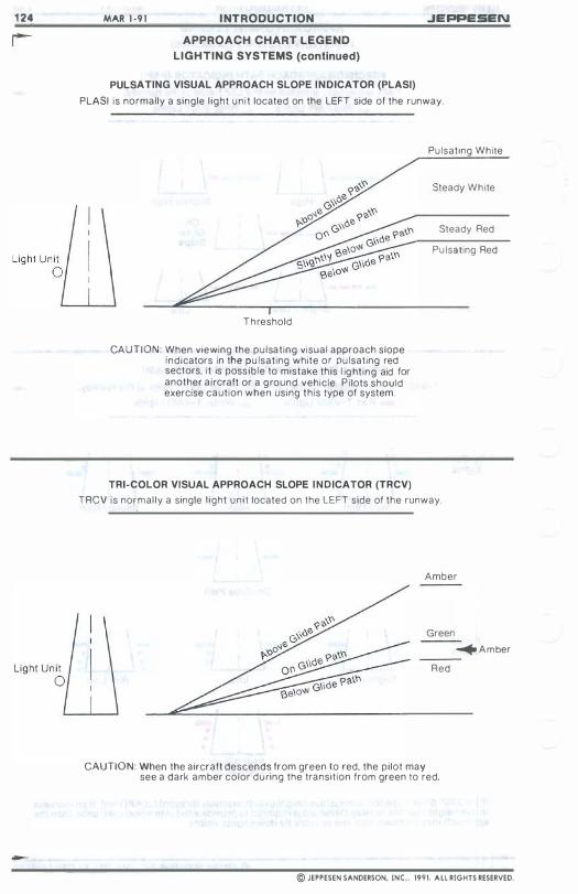
1 24
-
MAR 1 ·9 1 I NTRODUCTION
APPROACH CHART LEGEND
LIGHTING SYSTEMS (continued)
JEPPESEN
PULSATING VISUAL APPROACH SLOPE INDICATOR (PLASI)
PLASI is normally a single l ight u n i t located on the LEFT side of the runway.
T h reshold
CA UTION: When viewing the pulsat ing visual approach slope indicators in the pu lsating white or pu lsating red sectors, it is possib le to mistake this l ig ht ing aid for another aircraft or a g round vehicle P i lots should exercise caut ion when using th is type of system.
Pu lsating White
Steady White
Steady Red
Pu Isating Red
TRI-COLOR VISUAL APPROACH SLOPE INDICATOR (TRCV)
TRCV is normal ly a single l ight u n i t located on the LEFT side of the runway.
Amber
Green
� A m ber
Red
CAUTION: When the aircraft descends from green to red, the pilot may see a dark amber color d u ring the transit ion from green to red,
© JEPPESEN SANDERSON, INC., 1991. All RIGHTS RESERVED.
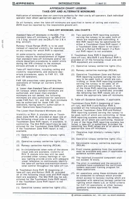
::JEPPESEN INTRODUCTION 1 1 MAY 0 1 1 25
APPROACH CHART LEGEND TAKE-OFF AND ALTERNATE MINIMUMS
Publication of minimums does not constitute authority for their use by all operators. Each individual operator must obtain appropriate approval for their use.
On a l l formats , when the take-off m inimums are spec i f i ed in terms of cei l i ng and v i s i b i l i t y , 80TH m u s t b e reported by t h e respons ib le ground un i t .
TAKE-OFF MINIMUMS, USA CHARTS
Standard Take-off Minimums in the USA: The standard take-off m in imums i s RVR 50 0,] for 1 & 2 Eng. ai rcraft and RVR 24 0r Y2 for 3 & 4 Eng. aircraft .
Runway V isual Range (RVR) is to be used i nstead of reported v i s i b i l i t y for operating on any runway for which RVR is reported.
At some a i r ports, obstruc t i ons or other factors req u i re the establ ishment of h igher than standard take-off m in imums and/or obstacle departure procedures to assist p i lots during the IFR c l i mbout to the min imum enroute a l t i tude or cruis ing a l t i tude.
Take-off restr ict ions, inc luding ce i l ing and v i s i b i l i ty requirements, and obstac l e departure procedures, apply to FAR 1 2 1 , 129 and 1 35 operators.
FAR 1 29 prescri bes rules governing the operations of fore i gn air carriers w i t h i n t h e USA.
A. Lower- than-Standard Take-off MinImums: On runways where standard min imums are authorized , and lower-than-standard min imums are not denied, the fol lowing minimums are also authorized for operators under FAR Part 1 2 1 . and 1 29. Such min imums may be autho r i zed for those FAR 135 operators, hav i ng spec i f i c autho r i zat ion in their Operat ions Spec i f i cat ions.
The lower-than-Standard M i n imums are:
V i s i b i l i t y or RVV Y. statute mile or Touchdown Zone RVR 1 6, provided at least one of the fol l ow ing v isual a ids is ava i lable. The Touchdown Zone RVR report, if ava i l ab le , is contro l l ing. The M i d RVR report may be subs t i tuted for the Touchdown Zone RVR report if the Touchdown Zone RVR report is not avai lable.
( 1 ) Operat ive h igh intenSity runway l ights ( HIRl)
(2) Operat ive runway center l ine l ights (Cl) .
(3) Runway center l ine mark i ng (RClM) .
(4) In c i rcumstances when none of t h e above v isual a ids are ava i lable , v i s i b i l i ty or RVV Y. statute m i l e may s t i l l be used , provided other runway mar k i ngs or runway l ight ing provide p i lots w i t h adequate visual reference to cont inuously ident i fy the take-off surface and mainta in d i rectional control throughout the take-off run.
B. Touchdown Zone RVR 10 (beginning of take-off run) and Rol lout RVR 10, provided all of the fol lowing v isual a ids and RVR equipment are ava i lab le . The Mid RVR may be subst i tuted for the Touchdown Zone RVR report i f the Touchdown Zone RVR report I s not avai lable.
( 1 ) Opera t i ve runway centerl ine l ights (Cl).
(2) Two operative RVR report ing systems serving the runway to be used, both of which are required and control l ing . A M i d RVR report may be subst i tuted for ei ther a Touchdown Zone RVR report i f a Touchdown Zone report i s not ava i l a b l e or a Rol l out R V R report i f a Rol lout RVR report i s not avai lab le .
C. Touchdown Zone RVR 5 (beg inning of take-off run ) , M i d RVR 5 and Rol lout RVR 5 , provided a l l of the fol l owing v isual a ids and RVR equipment are avai lab le .
( 1 ) Opera t i ve runway center l ine l ights (Cl) .
( 2 ) Runway centerl ine markings (RClM ) .
( 3 ) Operat ive Touchdown Zone and Rol l out RVR report i ng systems serving the runway to be used , both of which are contro l l ing, or three RVR report ing systems serving the runway to be used , all of which are control l ing. However, i f one of the three RVR report i ng systems has fa i led , a take-off i s author i zed, provided the remain ing two RVR values are at or above the appropr iate take-off min imums.
D. Take-off Guidance System, i f appl i cable.
Touchdown Zone RVR 3 (beginning of take-off run) , M i d RVR 3 and Rol lout RVR 3 , provided a l l t h e fol lowing a i d s a r e ava i lable. Opera t i ve Touchdown Zone RVR and Rol lout RVR report ing systems serving the runway to be used, both of which are contrO l l ing , or three RVR report i ng systems serv i ng the runway to be used, al l of which are control l ing. However if one of the three RVR report i ng systems has fai l ed , a take-off i s author ized, provided the remain ing two RVR val ues are at or above the appropr iate take-off m in imums.
( 1 ) Operative h igh intens i t y runway l ights ( HIRl)
( 2 ) Operat ive runway center l ine l ights (Cl).
(3) Serviceable runway center l i ne mark ings (RCl M ) .
(4) Front course guidance from t h e loca l i zer must be avai lable and used ( i f appl icable to gu idance system used) .
(5) The reported crosswind component shal l not exceed 10 knots.
(6) The p i lot i n command and the second in command have completed the cert i f i cate holders approved train ing program for these operati ons.
(7) A l l operations us ing these min imums shal l be conducted to runways which provide d i rect access to taxiway routing which are equi pped with opera t i ve taxiway center l i ne l ight ing which meets U .S . or ICAO c r i ter ia for CAT I I I operations; or other taxiway guidance systems approved for these operations.
© JEPPESEN SANDERSON, INC., 199 1 , 2001 . ALL RIGHTS RESERVED.
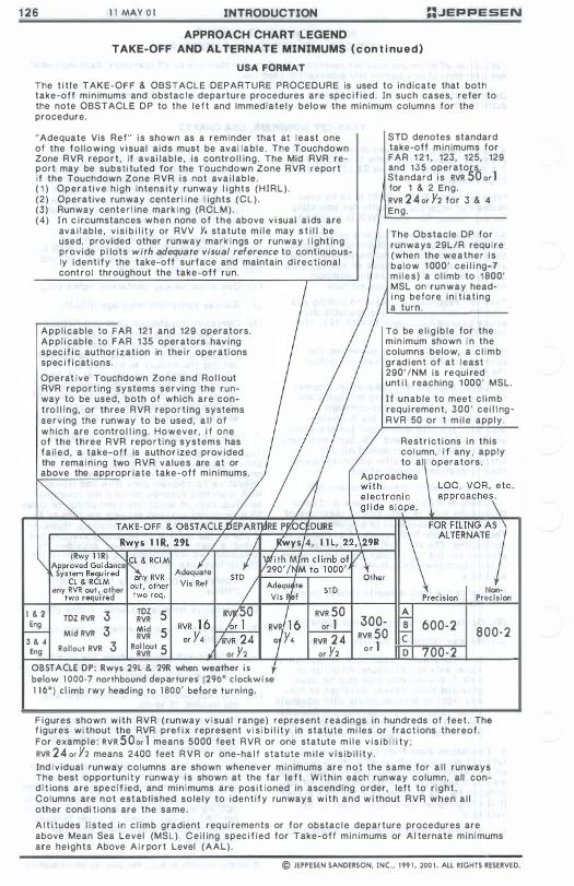
1 26 1 1 MAY 0 1 INTRODUCTION ::JEPPESEN
APPROACH CHART LEGEND TAKE-OFF AND ALTERNATE MINIMUMS ( c on t i nued)
USA FORMAT
The t i t le TAKE-OFF & OBSTACLE DEPARTURE PROCEDURE is used to indicate that both take-off min imums and obstac le departure procedures are spec i f ied. In such cases, refer to the note OBSTACLE DP to the left and Immediate ly below the min imum columns for the procedure.
"Adequate Vis Ref" i s shown as a reminder that at l east one of the fo l lowing v isual aids must be avai lab le . The Touchdown Zone RVR report , if avai lab le , is contro l l ing. The Mid RVR report may be substi tuted for the Touchdown Zone RVR report if the Touchdown Zone RVR i s not ava i l ab le . ( 1 ) Operat ive h igh intens ity runway l ights (HIRL) . (2) Operative runway center l ine l ights (CL) . (3) Runway cente r l ine mark i ng (RCL M ) . (4) I n c i rcumstances w h e n none of t h e above v i sual a i ds are
ava i l ab le , v i s i b i l i ty or RVV Y. statute m i l e may s t i l l be used, provided other runway mark ings or runway l ight ing provide p i lots with adequate visual reference to continuously ident ify the take-off surface and maintain d i rect ional control throughout the take-off run.
App l icable to FAR 121 and 129 operators. App l i cable to FAR 1 35 operators hav i ng spec i f i c author izat ion in the i r operations spec i f i cat ions.
Ope rat ive Touchdown Zone and Ro l l out RVR report ing systems serving the runway to be used, both of which are contro l l ing, or three RVR repor t ing systems serving the runway to be used , a l l of which are contro l l ing. However, i f one of the three RVR report ing systems has fa i led , a take-off is author ized prov ided the rema i n i ng two RVR values are at or above the appropr iate take-off min imums.
1 & 2 3 TOZ 5 TOZ RVR RVR Eng Mid Mid RVR 3 RVR 5 3 & 4 Rollout RVR 3 Eng R'II��ut 5 or Y2
OBSTACLE DP: Rwys 29L & 29R when weather i s below 1 000-7 northbound departures (296' c lockwi se 1 1 6') c l imb rwy heading to 1 800' before turning.
RVR 50 or 1
RVR 2 4 or Y2
STD denotes standard take-off m i n imums for FAR 1 2 1 , 123, 125, 129 and 1 3 5 operators. Standard i s RVR 50 or 1 for 1 & 2 Eng. RVR 2 4 0r Y2 for 3 & 4 Eng.
The Obstacle DP for runways 29L/R requ ire (when the weather I s be low 1 000' cei l i ng-7 m i l e s ) a c l imb to 1 800' MSL on runway headi ng before in i t iat ing a turn.
To be e l i g i b l e for the min imum shown i n the columns below, a c l imb grad i ent of at l east 290' INM is requi red unt i l reaching 1 000' MSL.
I f unable to meet c l imb requi rement , 300' cei l l ngRVR 50 or 1 m i l e apply.
Restr ict ions i n this col umn, i f any , apply to al l operators.
A 300- B 600-2 RVR 50 C 800-2
o r 1 D 700-2
F igures shown w i t h RVR ( runway v isual range) represent readings in hundreds of feet . The f igures wi thout the RVR pref i x represent v i s i b i l i ty in statute mi les or fract ions thereof. For exampl e : RVR 5 0 0r 1 means 5000 feet RVR or one statute m i l e v i s i b i l i ty ; RVR 24 0r Y2 means 2400 feet R V R or one-ha l f statute m i l e v i s i b i l i ty . Ind i v idual runway co lumns are shown whenever m i n imums are not the same for a l l runways The best opportun i ty runway i s shown at the far le f t . Wi th in each runway column, all cond i t ions are spec if ied, and min imums are pos i t ioned in ascending order, left to r ight . Columns are not estab l ished sole ly to ident ify runways with and w i thout RVR when a l l other condi t ions are the same.
A l t i tudes l i s ted in c l imb gradient req u i rements or for obstac l e departure procedures are above Mean Sea Level (MSL). C e i l ing spec i f i ed for Take-off min imums or A l ternate min imums are heights Above A i r port Level (AAL) .
© JEPPESEN SANDERSON, INC., 199 1 , 200 1 . All RIGHTS RESERVED.

:;.JEPPESEN INTRODUCTION 1 1 MAY 0 1 1 27
APPROACH CHART LEGEND TAKE-OFF AND ALTERNATE MINIMUMS (con t i nued)
TAKE-OFF MINIMUMS, WORLDWIDE CHARTS Publication of minimums does not constitute authority for their use by all operators. Each individual operator must obtain appropriate approval for their use. On a l l formats, when the take-off m i nimums are speci f i ed in terms of cei l ing and v i s i b i l i ty, both values must be reported by the respon s i b l e ground u n i t .
The take-off minimums pub l ished under t h e t i t le A I R CARRIER a r e based o n Joint Aviation Regu lation Operations Subpart E . On charts dated prior to 12 Nov 99, the take-off minimums are published based on ICAO/ ECAC guidance mater i a l supported by adopted practice.
Take-off minimums pub l i shed under the t it le AIR CARRIER (FAR 1 2 1 ) are based on U.S. Operations Specifications.
The appl ication of these take-off min imums may be l imi ted by the obstacle envi ronment i n the takeoff and departure area. The RVR/VIS mi nimums are determined to ensure the v i sual guidance of the a i rcraft dur i ng the take-off run phase. The subsequent cl earance o f obstacles is the respon s i b i l i ty of t h e operator.
RVR and v i s i b l i ty values are shown i n measuring units as reported by the governing agency.
The t i t l e TAKE-OFF & DEPARTURE PROCEDURE i s used to indicate that both take-off minimums and departure procedures are spec i f i ed . In such cases, refer to the note DEPARTURE PROCEDURE to the left and immediately below the m i nimum colums for the procedure.
WORLDWIDE FORMAT FOR NON-FAA OR JAA MEMBER
STATES ON CHARTS DATED ON OR AFTER I I MAY 0 1 .
TAKE-OFF
AIR CARRIER AIR CARRIER (FAR 1 2 1 )
LVP must b .. i n Fore .. Rwys 07, 08, 25,26 Rwys 07, 08, 25,26 ALL Rwys ALL Rwys CL & RCLM
RL & CL RCLM (DAY on ly) or RL RCLM (DAY on ly)
or RL any RVR out, other two reQ. As�q�::e
Rwys 02L, 20R
A�r;�:le A 2 TDZ RVR 150m rs i-=- 200m ( 150m) 25fm C " .OOm 0 250m (200m) r--..... Jojm /"
These minimums are provided for operators not applying take-off minimums as speci f i ed under Air Carr ier (FAR 1 2 1 ) . RVR/VIS i n parentheses apply only if TDZ RVR i s supp lemented by RVR reports at mid runway and/or r o l l -out end. The TDZ R V R can be determined by the p i l ot from the take-off pos i t i on and is considered f o r the app l i cat ion o f these m i n i mums. Therefore, R V R / V I S m i n i mums appropr i ate to TDZ RVR may be charted, even though the RVR may not be i nstal led. Take-off m i n i mums wi thout spec i f i c runway centerl ine markings (day only) should be at least SOOm. A low Vis i b i l i ty Take-off w i t h RVRIVIS below 400m requires the ver i f i cation that low Vis ib i l ity Procedures (lVPs) have been established and are in force (all CAT II/III approved aerodromes ) . The fol lowing guidance has been estab l ished for aerodromes not approved for CAT II/III operations.
Unt i l such time that the concept for lVPs is also established for such aerodromes, the commander must satisfy himself w i t h A i r Traffic Services, or the Aerodrome Operator, that for a low Vis ib i l i ty Take-off only one aircraft at a time i s on the maneuvering area, and that vehicle traffic on the maneuvering area i s controlled and restr icted to the absolute m i n i mum.
Eng RVR 500m RVR 500m - Mid RVR 150m 3 & 4 VIS ., VIS .OOm Eng �oll out RVR 150m / Author i zed lower-than-standard take-off m i n i mums o f RVR 500m VIS 400m must be increased to the standard RVR 1500m or VIS 1600m for 1 & 2 eng. a i rcraft and to RVR 720m or VIS 800m for 3 & 4 eng. aircraft, unless one of the followi ng visual aids is ava i lab le .
"Adequate Vis Ref" i s shown as a reminder that at least one of the fol lowing visual aids must be avai lab le . The Touchdown Zone RVR report, i f avai l a b l e , i s cantral l ing. The M i d R V R report may b e subs t i tuted f o r t h e Touchdown Zone RVR report i f the Touchdown Zone RVR report i s not avai lab le . ( 1 ) Operat i ve h igh intenSity runway l ights
(HIRl). (2) Operative runway centerl i ne l i ghts (Cl) . (3) Runway center l ine marking (RClM). (4) In c i r cumstances when none o f the above v isual a ids are ava i l ab le , 400m v i s i b i l i ty [RVR SOOm V i s 400m ( R V R 16 o r Y, ) ] may s t i l l b e u s e d , p r o v i d e d o t h e r runway m a r k i n g s o r runway l i g h t i ng p r o v i d e p i lots with adequate visual reference t o cont i nuous l y i d e n t i f y t h e take-off surface and maintain d i rectional control throughout the take-off run.
© JEPPESEN SANDERSON, INC., 1989, 200 1 . All RIGHTS RESERVED.
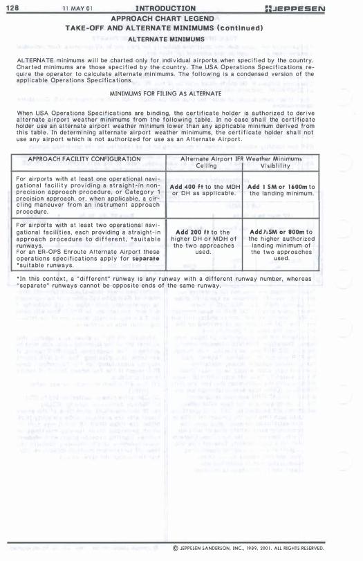
1 2 8 1 1 MAY O I I NTRODUCTION =:.JEPPESEN APPROACH CHART LEGEND
TAKE -OFF AND ALTERNATE MINIMUMS (cont i nued)
ALTERNATE MINIMUMS
ALTERNATE minimums w i l l be charted only for ind iv idual a i rports when spec i f ied by the country. Charted minimums are those spec i f i ed by the country. The USA Operations Spec i f i cat ions require the operator to ca lculate a lternate mi nimums. The fol lowing is a condensed version of the app l icable Operations Specif icat ions.
MINIMUMS FOR FILING AS ALTERNATE
When USA Operations Spec i f icat ions are binding, the cert i f icate holder is authorized to der ive a l ternate a i rport weather min imums from the fol lowing table . In no case sha l l the cert i f icate holder use an al ternate ai rport weather minimum lower than any app l i cable m in imum derived from th is table. In determi n i ng al ternate ai rport weather m i n imums, the cert i f i cate holder sha l l not use any a i rport which is not authorized for use as an A lternate Ai rport.
APPROACH FACILITY CONFIGURATION Alternate Airport IFR Weather Min imums Cei l ing Vis ib l i l ity
For ai rports with at least one operational nav i -gat iona l fac i l i t y prov i d i ng a stra ight- In non- Add 400 ft to the MDH Add 1 5M or 1 600m to precis ion approach procedure , or Category 1 or DH as appl icable . the landing mi nimum. precision approach, or , when applicable, a cir-c l i ng maneuver from an i nstrument approach procedure.
For airports with at least two operational nav i -gational fac i l i t i es, each providing a straight- in Add 200 ft to the Add Y,5M or 800m to approach procedure to d i f f ere n t , ' s u i t a b l e higher D H o r M D H o f the h igher authorized runways. the two approaches landing m i n imum of For an ER-OPS Enroute Alternate Airport these used. the two approaches operations spec i f i cat ions app l y for separate used. 'suitable runways.
' In this context , a "di fferent" runway Is any runway with a d ifferent runway number, whereas "separate" runways cannot be oppos ite ends of the same runway.
© JEPPESEN SANDERSON, INC., 1989, 200 1 . ALL RIGHTS RESERVED.
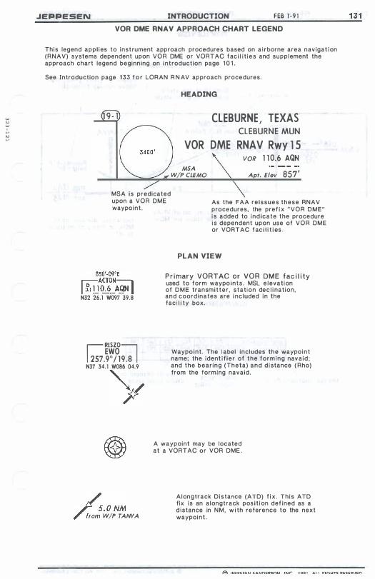
w t;
, >-' N >-'
.JEPPESEN INTRODUCTION FEB 1 -9 1 VOR DME RNA V APPROACH CHART LEGEND
This legend appl ies to instrument approach procedures based on airborne area navigat ion (RNAV) systems dependent upon VOR DME or VORTAC fac i l i t ies and supplement the approach chart legend beginning on introduction page 1 0 1 . See Introduction page 133 f o r LORAN R N A V approach procedures.
HEADING
CLEBURNE, TEXAS G.400'
CLEBURNE MUN
VOR DME RNA V Rwy 1 5
MSA W/P CLEMO
VOR 1 1 0.6 AQN Apt. Elev 857'
MSA is predicated upon a VOR DME waypoint.
As the FAA reissues these RNA V procedures, the pref i x "VOR DME" is added to indicate the procedure is dependent upon use of VOR DME or VORTAC fac i l i t i es .
850'-09°E r;;-:-: ACTON:=:l I I�) U 1l.:E._ A.9N I N32 26.1 W097 39.8
�RISZO� EWO
257.9° / 19.8 N37 34.1 W086 04.9
Y
/..O NM /".0'; W/P TANYA
PLAN VIEW
Pr imary VORTAC o r VOR DME fac i l i ty used to form waypoints. MSL e levation of DME transmitter , station dec l i nation, and coordinates are included in the faci l i ty box.
Waypoint . The l abel includes the waypoint name; the ident i f ier of the forming navaid; and the bearing (Theta) and d istance ( Rho) from the forming navaid.
A waypoint may be located at a VORTAC or VOR DME .
Alongtrack Distance (ATD) f i x . This ATD fix is an alongtrack pos i t ion def ined as a distance in NM, w i th reference to the next waypoint .
1 3 1

1 3 2 FEB 1 · 9 1
A!ongtrack Fix
RISZO
INTRODUCTION JEPPESEN
PROFILE VIEW
Missed Approach Point
Height of VNAV g l ide slope above runway threshold
046� -- 226° 4 NM
2500 ' ( 17J2')
I
5.0 3.9
Intersection of VNAV g l ide s lope and MDA
TOZE 768 ' APT. 775'
Horizontal distance from MDA on VNAV g l ide slope to MAP
CONVERSION TABLE
Gnd s ed·Kts GS Sett; 3 . 17°
AP at W P TANYA
140 160 797 9 1 1
Mi ssed Approach Point VNAV g l ide slope setting
Rates of descent on VNAV g l ide slope
© JEPPESEN SANDERSON, INC" 1 99 1 . ALL RIGHTS RESERVED.
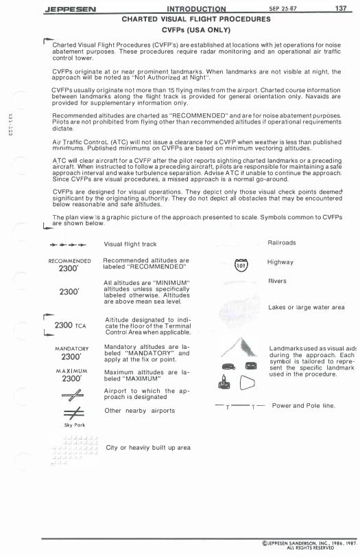
.JEPPESEN INTRODUCTION SEP 25-87
CHARTED VISUAL FLIGHT PROCEDURES
CVFPs (USA ONLY)
1 37
�Charted Visual Fl ight Procedures (CVFP's) are established at locations with jet operations for noise abatement purposes. These procedures require radar monitoring and an operational air traffic control tower.
CVFPs originate at or near prominent landmarks. When landmarks are not visible at n ight, the approach will be noted as "Not Authorized at Night".
CVFPs usually or iginate not more than 15 flying mi les from the ai rport. Charted course information between landmarks along the flight track is provided for general orientation only. Navaids are provided for supplementary information only.
Recommended altitudes are charted as "RECOMM EN DED" and are for noise abatement purposes. Pilots are not prohibited from flying other than recommended altitudes if operational requ i rements d ictate.
A i r Traffic Control (ATC) wi l l not issue a clearance for a CVFP when weather is less than published min imums. Published min imums on CVFPs are based on min imum vectoring altitudes.
ATC will clear ai rcraft for a CVFP after the pi lot reports sighting charted landmarks or a preced i ng aircraft. When instructed to follow a preceding ai rcraft, p i lots are responsible for maintaining a safe approach i nterval and wake turbulence separation. Advise ATC if unable to continue the approach. Since CVFPs are visual procedures, a missed approach is a normal go-around.
CVFPs are designed for visual operations. They depict only those visual check points deemedsign ificant by the origi nating authority. They do not depict all obstacles that may be encountered below reasonable and safe altitudes.
The plan view is a g raphic picture of the approach presented to scale. Symbols common to CVFPs l--are shown below.
RECOMMENDED 2300'
2300'
r-2300 TCA
l--MANDATORY
2300' M A X I MUM
2300'
Sky Park
Visual f l ight track
Recommended altitudes are labeled "RECO M M ENDED"
Al l altitudes are " M I N I M U M" altitudes u nless specifically labeled otherwise. Altitudes are above mean sea level.
Altitude designated to indicate the f loor of the Terminal Control Area when applicable.
Mandatory altitudes are labeled "MANDATORY" and apply at the fix or point.
Maximum altitudes are labeled " MAXIMUM" A i rport to wh ich the approach is designated
Other nearby ai rports
City or heavily bui l t up area
- .
� D
Rail roads
H ighway
Rivers
lakes or large water area
landmarks used as visual aid! dur ing the approach. Each symbol is tailored to represent the specific landmark
- used in the procedure.
- T -- T - Power and Pole line.
©JEPPESEN SANDERSON, INC., 1986, 1987. All RIGHTS RESERVED

INTENTIONALL Y
LEFT
BLANK

.JEPPESEN I NTRODUCTION 13 DEC 96 APPROACH CHART LEGEND
GPS APPROACH CHARTS This GPS Approach Chart Legend supplements the standard approach chart legend beginning on Introduction Page 101 . Equipment requirements, database requirements, and requirement or non-requirement for monitoring conventional navaids are not addressed in this legend-Refer to Jeppesen Air Traffic Control (ATC) pages for this information. [For the United States, refer to the Jeppesen Navigation Aids pages of the A irman's Information Manual.]
STAND ALONE GPS APPROACH. Procedure i s included in Jeppesen's NavData Service. GPS APPROACH, over l ies an establ ished
conventional nav igat ion non-prec i s ion approach. Procedure i s included in Jeppesen' s NavData Service.
1 47
� FREDERICK, MD �EDERICK MUN
GPS Rwy 5
� OAKLEY, KAN � OAKLEY MUN
NOB or GPS Rwy 34 �KFDK Apt. Elev 304'
/ 1 NDB 3 8 0 OEL � KOEL Apt. Elev 3044' I A i rport ident i f ier to ass ist in select ing the
appropriate a i rport informat ion f rom the database.
GPS OVERLAY, over l i es an establ i shed conventional nav igat ion non-precis i on GENEVA, SWITZERLAND approach. Note that GPS is not part of instrument approach procedure t i t le. COINTRIN (GPS) indicates G P S approach informat ion has been a�pl.ied to th� approach chart. GV A VORDME Rwy 23 Procedure IS Included In Jeppesen's -----.::..:.:. NavData Service. (GPS) VOR 1 1 4 . 6 GVA
A i r port ident i f ier to assist in select ing the _____ LSGG Apt. Elev 1 4 1 1 ' approp r i ate a i rport information from the database.
I
Jeppesen database identifiers are always shown in italic type. They are enclosed within square brackets, as [D255G], or prior to October 1994 within parentheses, as (D255G).
For Stand A l one GPS approaches, four corner waypoint symbols are used for most f i xes.
MYRTA [RW{J5]
'" [RW{J5] - Missed approach i s at Runway 5 threshold.
2. 5 NM tO BAKEE �
2.5 to BAKEE - A l ong track d istance.
© JEPPESEN SANDERSON, INC., 1995, 1996. All RIGHTS RESERVED.

1 4 8 1 3 DEC 96 INTRODUCTION JEPPESEN
APPROACH CHART LEGEND GPS APPROACH CHARTS ( cont i nued)
F o r " N O B or GPS" type approaches and for GPS overl ays , waYPoint symbol is used most ly for f i xes that would otherwise be shown as pos i t ion f i xes w i t h no t r i ang le f i x symbol or for added database f i xes not part of the convent ional non-precis ion navigation approach.
Turn points where headings or courses intersect courses between IAF and FAF.
1 "" � -Ut o- -;" o � .., (IAF) 0 \0
LAHAB NORWA " _DI6'O!\'� 076" D'�."
--26 J O 2.3 • t-2500 to NORWA � 0 D20 26 1 0 7. 8 '" � t\ 2500 [SL/B]
'" [SL/7] .j>. 0
Jj$
[RWJ5Rj
*
(IAF)
[D26.o1PJ IAFs def ined by radia ls on DME arc procedures.
�D 17.2 DEN 2.5 NM to MAP
2.5 NM to MAP - For t i med approaches, di stance from stepdown f i x to MAP i s inc luded.
Sensor FAFs 0 on No-FAF procedures.
\ NDB --�'!JS0:l 2400' 5 1 0 NM �(2 145') 058 0 [FF� }
from __ � �B M'
Sensor FAF p lacement in prof i l e v iew for n o F A F procedures. D i stance to MAP i s i nc luded.
TOZE 2 5 5 '
o Def in i t ion: A Sensor FAF i s a f ina l approach waypoint created and added t o the database sequence of waypoints to support GPS navigation of a pub l i shed, no FAF, non-prec is ion approach. The Sensor FAF i s inc luded in Jeppesen's NavData waypoint sequence and inc luded in the p lan and prof i l e v iews of no FAF non-prec i s i on approach charts. In some cases, a s tep down f ix , recogn ized by a charted database ident i f ie r , may serve as the Sensor FAF.
r AIRSPACE FIXES
l-
t:,. <} X - Non-Compulsory A irspace f i xes.
1;,. -+ - Compulsory A i rspace f i xes.
@@@@@- F l y-over A i rspace f ixes .
© JEPPESEN SANDERSON, INC., 1995, 1996. ALL RIGHTS RESERVED.
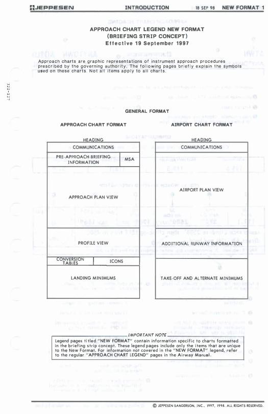
::JEPPESEN INTRODUCTION 18 SEP 98 NEW FORMAT 1
APPROACH CHART LEGEND NEW FORMAT (BRIEF ING STR IP CONCEPT )
E f f e c t i ve 1 9 Sept ember 1 9 9 7
Approach charts are graphic representat ions of instrument approach procedures prescr i bed by the governing author i t y . The fo l lowing pages b r i ef l y expla in t he symbol s used o n these charts . N o t a l l i tems a p p l y to a l l charts .
GENERAL FORMAT
APPROACH CHART FORMAT AIRPORT CHART FORMAT
HEADING HEADING
COMMUNICATIONS COMMUNICATIONS
PRE·APPROACH BRIEFING I MSA I NFORMATION
AIRPORT PLAN VIEW
APPROACH PLAN VIEW
PROFILE VIEW ADD ITIONAL RUNWAY INFORMATION
CONVERSION I ICONS TABLES
LANDING MINIMUMS TAKE-OFF AND AL TERNATE MINIMUMS
,-________________________ IMPORTANT NOTE ________________________ -, Legend pages ti tled "NEW FORMAT" contain information spec i f i c to charts formatted in the br ief ing str ip concept. These legend pages include on ly the i tems that are unique to the New Format. For inform"tion not covered in the "NEW FORMAT" legend, refer to the regular " APPROACH CHART LEGEND" pages in the Airway Manual .
© JEPPESEN SANDERSON, INC . . 1997, 1998. All RIGHTS RESERVED.
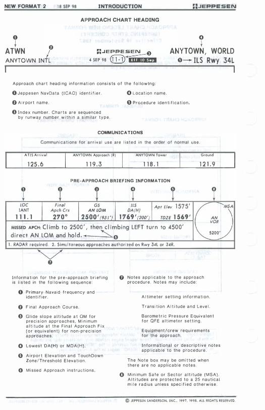
NEW FORMAT 2 1 e SEP 98 INTRODUCTION ::.JEPPESEN
APPROACH CHART HEADING
o o t
ATWN f) I
t ANYTOWN, WORLD
ANYTOWN INTL 0---+- ILS Rwy 34L
A pproach c h a r t head i ng i n f o r m a t ion cons i s ts o f t h e f o l l o w 1 n g :
o J e p p e s e n NavData ( I C A O ) iden t i f i e r . o Locat ion name.
f) A i r po r t name. o Procedure ide n t i f i c a t i o n .
o I n d e x numb e r . C h a r t s a r e sequenced by runway numbe r w i t h i n a s i m i l a r t y p e .
COMMUNICA TIONS Commun i c a t i ons for a r r i v a l use are I i s t e d i n the order of normal u s e .
A T i S ArrivBI ANYTOWN Approach (R) ANYTOWN Tower Ground
1 25 . 6 1 1 9 . 3 1 1 8 . 1 1 2 1 . 9
PRE-APPROACH BRIEFING INFORMATION
T
o
LOC IANT
1 1 1 . 1 2700 2500 '(93 1 ') 1 76 9 ' (200 ') TDZE 1 569 ' AN VOR
Final GS ILS Ap.t flev 1 575' I ( ....... MSA
Apch Crs AN LOM DA (H)
) MISSED APCH: C I imb to 2500 ' , then c I imbing L EFT turn to 4500' , d i rect AN LOM and ho ld . ... '" (} 5200
1 . RADAR required. 2. Simu l taneous approaches authori zed on Rwy 3�l or 34R.
Info rma t i on for the p r e - approach b r i ef i ng is l i s ted in the f o l l o w i n g sequence:
o P r imary Navaid f r equency and i d e nt i f i e r .
f) F i nal A pproach C o u r s e .
o G l id e s l o p e a l t i tude a t OM f o r p re c i s i o n approaches, M i n i mum a l t i t u d e a t t h e F i n a l A p proach F i x ( o r equ i v a l e n t ) f o r non-pr e c i s i on a p proaches.
o Lowest D A ( H } or M D A ( H } .
o A i rp or t E l e v a t i on a n d TouchDown ZonefThreshold E l ev a t i on .
(} M i ssed A pproach i n s t r u c t i ons.
o Notes a p p l i c a b l e to t h e approach procedur e . N o t e s may i n c l u d e :
A l t i m e t e r s e t t i n g i n f o r m a t i o n .
T r ans i t i o n A l t i tude a n d Leve l .
Barome t r i c P r e s s u r e Equi v a l en t f o r Q F E a l t i m e t e r s e t t i n g .
E q u i pment / c r e w requi rements for t h e approach.
I n formational Of descr i p t i v e notes a p p l i c a b l e to the procedure.
T h e N o t e box may be omi t ted when t here a r e no a p p l i c a b l e n o t e s .
o M i n i mum S a f e or Sector a l t i t ude ( M S A ) . A l t i tudes are p r o t e c t e d to a 25 n a u t i c a l m i l e r a d i u s u n l es s spec i f i ed o t h er w i s e .
© JEPPESEN SANDERSON. INC., 1997, 1998. All RIGHTS RESERVED.
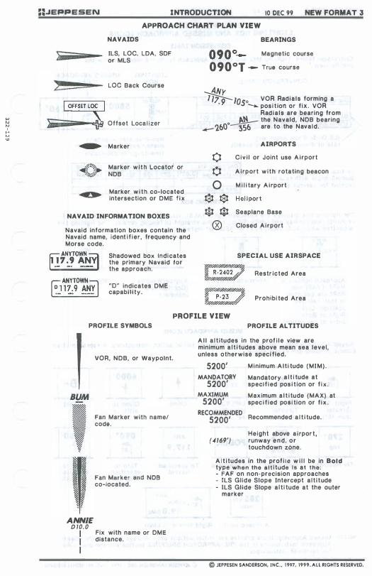
==.JEPPESEN INTRODUCTION 10 DEC 99 NEW FORMAT J
APPROACH CHART PLAN VIEW
NAVAIDS
ILS, LOC, LOA, SOF or MLS
Loe Back Course
}jli_iiiiiiiil-"'� Offset Local izer
� Marker
�t�' Marker· with Locator or �J� NOB
Marker with co-located intersection or OME f ix
NAVAID INFORMATION BOXES
Navaid information boxes contain the Navaid name, ident i f ier , frequency and Morse code.
f!ANYTOW� 1 7 . 9 A
.- _. -.
Shadowed box Indicates the primary Navaid for the approach.
"0" indicates OME capabi lity.
BEARINGS
Magnetic course
090°1 - True course
ANy � 10so VOR Radials forming a • __ posi t ion or f ix. VOR
Radials are bearing from � the Navald, NOB bearing
_ 2&0° 35& are to the Navald.
AIRPORTS
o Civ i l or Joint use Airport
¢ A irport with rotating beacon
o M i l i tary Airport
'�H' �H .... � Hel i port
$ ¢1 Seaplane Base
® Closed Airport
SPECIAL USE AIRSPACE
W"///////////h:l0W/� � P·23 � �$$/////ff
Restr icted Area
PrOhibi ted Area
PROFILE VIEW PROFILE SYMBOLS
,
ANNIE D 10. 0 I I I
VOR, NOB, or Waypolnt.
Fan Marker with name I code.
Fan M.arker and NOB co-located.
Fix with name or OME distance.
PROFILE ALTITUDES
A l l a l t itudes in the prof i l e view are minimum a l t i tudes above mean sea level , unless otherwise speci fied.
5200' Minimum Alt i tude (MIM) .
MANDATORY Mandatory a l t i tude at 5200' specif i ed pos i t ion or f i x .
MAXIMUM Maximum a l t i tude (MAX) at 5200' speci f i ed pOSi tion or f ix .
RECOMMENDED 5200' Recommended a l t i tude.
(-4169') Height above a i rport , runway end, or touchdown zOne.
A l t i tudes in the prof i l e w i l l be in Bold type when the alt i tude I s at the: - FAF on non-precision approaches - ILS Gl ide Slope Intercept a l t i tude - lLS Gl ide Slope a lt i tude at the outer
marker
© JEPPESEN SANDERSON, INC., 1 997, 1999. All RIGHTS RESERVED.

NEW FORMAT 4 1 0 OEC 99 INTRODUCTION ::.JEPPESEN
CONVERSION TABLES LIGHTING BOX AND MISSED APPROACH ICONS
CONVERSION TABLE
Conversion tables. L ight ing Box and M issed Approach Icons are located below the prof i le v iew.
CONVERSION TABLE
Gnd speed-Kts 70 90 100 120 140 160
GS 3.00· 377 484 538 645 753 86 1 �M to MAP 5 . 1 4:22 3:24 3:04 2:33 2: 1 1 1:55 r... IlS Gl ide Slope Ang le w i t h r a t e of descent a t var ious speeds.
Gnd speed-Kts
L I GHTING BOX
MISSED APPROACH ICONS
t t AlSF·1I 5800' 8000' -PAPllli
i t m ; �Non-precis ion Approach
missed approach point with t i me-to-go as appl icable.
70 90 100 120 140 160
2600 hdg
Vert ical Navigation (VNAV) descent angle with rate of descent for var ious speeds
� Descent angle [3.00"] 372 478 53 1 637 743 849
MAP at NOB LIGHTING BOX
The l ight i ng box d isp lays the approach l ights (ALS). v i sual approach s lope l ight ing (VASI or PAPI) . and runway end l ights (REIl) for the stra ight - in land ing runway. The l ight ing box i s omi tted when AlS. VASI. PAPI or REIl not insta l l ed.
ALSF·! �
VASI T T
Approach l i g hts and V ASI . (V ASI and PAPI are depicted i n their re lat ive pos i t ion; Left . Right or Both s ides of . center l ine) .
ITJ"·u
IH
T !
Approach l ights. Approach l i ghts . (Conf igurat ion unknown)
r:I.
L:l
REIl and VASI.
MISSED APPROACH ICONS
M i ssed Approach Icons i nclude a wide variety of in i t ia l act ion instruct ions. A representative sample of Icons are shown below;
0 EI 8J DJ 1 6°rl EI Right Turn left Turn Left Turn C l imb Climb to D i rect (greater (greater ( less than alt itude than 45") than 45") 45")
@] ANY IPOOOCI § I£I 1'···'1 1 1 1 .9 hdg R-210 1 1 1 _9 rrr m
Fly Headi ng Track Radia l To spe c i f i ed To spec i f i ed Turn to Turn to F ix Navaid specif ied spec i f i ed
Course Att i tude
285 kls I ANY
� wl ihin max : 9 .0 DME
Airspeed l imit Right turn with Limit
NOTE: M issed Approach Icons provide for i n i t i a l act ions only. A lways refer to the Missed Approach instruc t i ons i n the PRE-APPROACH BRIEFING section and the p lan v iew for complete instructions.
© JEPPESEN SANDERSON. INC . • 1997. 1999. ALL RIGHTS RESERVED.

U.JEPPESEN INTRODUCTION 10 OEC 99 NEW FORMAT 5
VERTICAL NAVIGATION (VNAV)
Vertical Navigation (VNAV) descent information w i l l appear in the prof i l e view of selected non-precis ion approaches beginning w i t h charts dated 3 Dec 1999. The VNAV Information appearing in the profile I l l ustrates the geometric descent path with a descent angie from the F i nal Approach Fix (FAF) to the ThreshOld Crossing Height (TCH) at the approach end of the runway.
The VNAV descent path, depicted with a screened l ine, Is based on the same descent angie coded into the Jeppesen NavData database. U5e of this descent angle by certif ied VNAV-capable avionics equipment w i l l ensure a stable, constant rate of descent that w i l l clear a l l Intervening a l t itude restrict ions. Some approach procedures may require a delay of the start of descent beyond the FAF, unt i l the VNAV descent path is I ntercepted. The prof i l e v iew w i l l depict this level segment of f l ight as required.
The VNAV descent angle appears In brackets along the VNAV descent path and is repeated in the conversion table. Addit ionally, the conversion table provides a recommended rate of descent relative to the VNAV angle and groundspeed.
The inclusion of the VNAV descent angle does not change or modify ex ist ing non-precision approach requirements. usage of the Minimum Descent Alt i tude (MDA), as wel l as the Missed Approach PoInt (MAP), remains unchanged. In accordance with Federal Aviation Regulat ions (FARs) and ICAO PANS OPS criteria, do not descend below the MDA until attain ing the required vi sual reference. Add i t iona l ly , do not i n i t iate the prescribed m i ssed approach procedure prior to reaching the published missed approach pOint. Note: Operators may obtain permission trom their contro l l i ng authority to use Decision A l t itude (OA) operational techniques when making a VNAV descent. This approval is specif ic to the operator and to the approach.
VNAV descent is optional. Use of any VNAV approach technique is dependent on operator approva l , cert i f ied VNAV-capable equipment availabi l i ty, and crew training.
(VNAV angle and database descent path)
" VCR RIVER
2700,1 (2068', r-004, 1 ..... 1 I
- 1: 1'��8�' +"�;;�yJ'J (RjJ6J
I ... . ... M/ [TCH 50'} 10.0 Gnd ,_·KII 70 90 100 120 "'.e«rl MIll. 3.23' �OO 5 � )7 686
,rOEIt 'o M""'- 5.0 � : 17 3:20 3:00 2:30
5.0
140 160 800 9U
2:08 1 :52
i I······ ·:l· roz.632 ' 5.0 0 1 1200' 12800'1 1 + l � -f)+- GINER
VNAV descent information from FAF to runway with TCH of 50' .
(VNAV angle and database descent path)
ESKAtO
9.8 16.8 7.0
Gnd , ·K.. 70 90 100 120 140 160 D.".", I. 3,50' �35 559 621 745 870 994
MA ... , .W"
s.o
OOnly aUlhorlzed operators may u • • VNAV DA(H) In lI.u 01 MDA(H).
VNAV descent Infor"",t lon from FAF to runway with TCH of �5' . Note that the VNAV path requires maintenance of level f l ight after the FAF, prior to intercepting the VNAV descent path of 3.50·, In order to cross the 2.0 NM to RW29 stepdown fix at or above 1390'. For approved operators, use of DA(H) operational technique on this approach Is Indicated by the ballflag note as well as by the dashed VNAV descent track in the prof i le v iew .
© JEPPESEN SANDERSON. INC., 1997, 1999. All RIGHTS RESERVED.
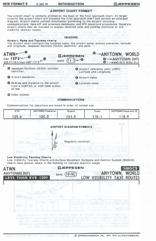
NEW FORMAT 6 10 DEC 99 INTRODUCTION ::.JEPPESEN
AIRPORT CHART FORMAT
The a i rport chart Is norma l l y printed on the back of the f i r s t approach cha r t . At larger a i r ports the a i r port chart w i l l preceed the f i rst approach chart and contain an enlarged d iagram. Ai rport charts contain information pertaining to the airport inc luding communications, take-off and a l ternate minimums, and IFR departure procedures. Separate a irport charts may be included to display deta i l ed ramp and parking pos i t i ons or low v is ib i l i ty taxiway routes.
HEADING Airpor t , Ramp and Taxiway charts The A i rport chart contains the location name, the ai rport name. a i rport e levat ion, l a t i tude and longitude, Jeppesen NavData ( ICAO) Iden t i f i er , and date.
ATWN--O Elev 1 515,.....--0 � 225,0°/ 13 ,0 from ANY 1 1 7.9
U.JEPPESEN
DATE QIJ) __ O O--ANYTOWN, WORLD
O-+ANYTOWN INTL O-N40 00,0 W104 5 1 .0
o Jeppesen NavData ( ICAO) location ident i f ier .
o A irport elevat ion,
€) Bearing and di stance to the airport from a VORTAC or VOR DME w ithin 40 NM.
o Index number.
° Ai rport reference point (ARP) Lat i tude and Longitude.
o Airport name,
o Location name.
COMMUNICATIONS
Communications f or departure are l isted In order of normal use.
ATiS ANYTOWN Clearance Ground Tower ANYTOWN Departure (R)
1 25 . 6 1 20 , 3 1 2 1 . 9 1 1 8 . 1 1 1 8 . 9
AIRPORT DIAGRAM SYMBOLS
Magnet ic var iat ion .
Low Visibi l i t y Taxiway Cha r t s Low Vis ibi l i ty Taxi way Charts a n d Surface Movement Guidance and Control System (SMGCS) charts have special labels in the heading t o indi cate spec i f i c usage.
ATWN ANYTOWN INTL
::.JEPPESEN 11ft@iJ ANYTOWN, WORLD
LOW VISIBILITY TAXI ROUTES DATE 00-9C)
© JEPPESEN SANDERSON, INC., 1997, 1999. ALL RIGHTS RESERVED .

n.JEPPESEN INTRODUCTION 1 6 AUG 02
SID/DP&STAR CHART LEGEND NEW FOR M AT
Effective 16 August 2002
NEW FORMAT 7
IMPORTANT NOTE _____________ --,
Legend pages titled "NEW FORMAT SID/DP/STAR" contain information specific to charts formatted in the new SID/DP/STAR chart concept. These legend pages include only those items that are unique to the NEW SID/DP/STAR FORMAT. For information not covered in the NEW FORMAT SID/DP/STAR chart legend, refer to the regular SID/DP/STAR chart legend pages in the Airway Manual.
SID/DP& STAR charts are graphic illustrations of the procedures prescribed by the governing authority. A text description may be provided, in addition to the graphic, when it is furnished by the governing authority. Not all items apply to all charts.
SID/DP/STAR CHART HEADING
e EDDF/FRA 0 �=.JEPPESEN FRANKFURT/MAIN GERMANY 0 I f) (lO-3H) lilll •• 11 o FRANKFURT/MAIN 21 JUN 02 lIB
FRANKFURT. Departure (R) Apt Elev TrIOn. level: By ATC Trena all: 5000' I . Contact FRANKFURT
0 1 20.42 364' f)
Departure immedi"tely "Iter take-off. 2. SID, are "Iso noi.e abatement "rocedurea (refer to. 10-4). Strict adherence within the e the limits of aircraft performace is mandatory. :
SID/DP/STAR chart heading consists of the following:
o City/Location and State/Country names. e Chart type identifier.
e CD G
Jeppesen NavDatalICAO/IATA airport identifier. 0 Airport name.
Revision date, index number and effective date. 0 Communication frequency.
Airport elevation. €) Common placement of notes applicable to the procedure.
SID/DP/STAR CHART PLAN VIEW PROCEDURE TITLE Navaids, intersections or waypoints identified in the procedure title (e.g., starting point of a STAR or end point of a SID/DP) are shown prominently for better identification. Navaid boxes will include a shadowed outline, intersection or waypoint names will be shown in larger text size.
Navaid rDINKnS8UHL� 1 1 7.8 DKS _ . . - _ ...
NoI9 08.6 E010 14.3
SPEED RESTRICTIONS
DINKELSBUL Departure
SKEBR
Intersection
SKEBR ONE Arrival
Speed restrictions that apply to the entire procedure are shown below the procedure title.
SYMBOLS fUn.' MAX 250 KT BELOW 10000'
RADIALS
VOR Radials forming a position or fix. VOR Radials are bearings from the Navaid. NDB bearings are to the Navaid.
AIRPORTS
o Civil or Joint use Airport
Airport with rotating beacon
o Military Airport
@ JEPPESEN SANDERSON. INC., 2002, ALL RIGHTS RESERVED.
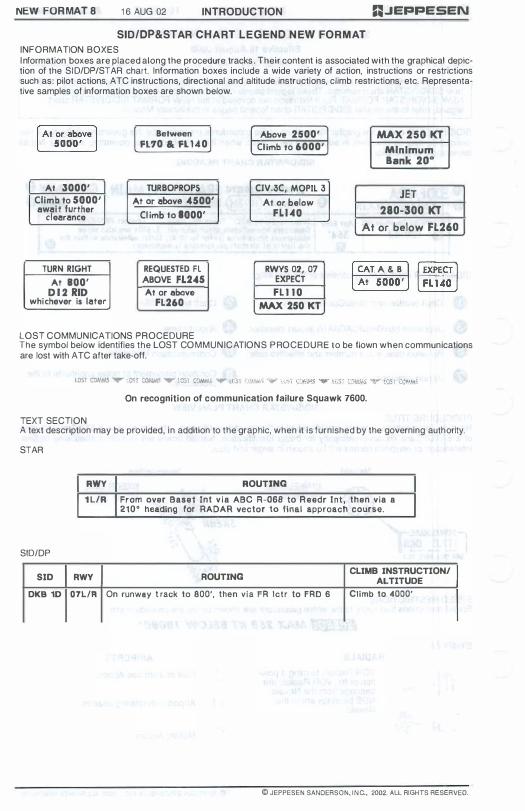
NEW FORMAT 8 1 6 AUG 02 INTRODUCTION R.JEPPESEN
SID/DP&STAR CHART LEGEND N EW FORMAT
INFORMATION BOXES I nformation boxes are placed along the procedure tracks. Their content is associated with the graphical depiction of the SID/DP/STAR chart. Information boxes include a wide variety of action, instructions or restrictions such as: pilot actions, ATC instructions, directional and altitude instructions, climb restrictions, etc. Representative samples of information boxes are shown below.
At 3000'
Climb. to 5000' Ilw8 it further
cle8r8nce
TURN RIGHT
At BOO' D I 2 RID
whichever is 18ter
Between FL70 & FL 140
TURBOPROPS
At or 8bove 4500'
Cl imb to 8000'
REQUESTED FL ABOVE FL245
At or above
FL260
Above 2500'
Cl imb. to 6000'
CIV.3C,. MOPIL 3
At or below
FLUO
RWYS 02, 07 EXPECT
FL I I O
MAX 250 KT
MAX 250 KT Minimum Bank 20°
JET
280-300 KT
At or. below FL260
LOST COMMUNICATIONS PROCEDURE The symbol below identifies the LOST COMMUNICATIONS PROCEDURE to be flown when communications are lost with ATC after take-off.
On recognition of communication failure Squawk 7600.
TEXT SECTION A text description may be provided, in addition to the graphic, when it is furnished by the governing authority.
STAR
RWY ROUTING
1 L/R From over Basel Int v ia ABC R-OS8 to Reedr Int, then via a 210· heading for RADAR vector 10 final approach course.
SID/DP
SID RWY ROUTING CLIMB INSTRUCTION!
ALTITUDE
DKB 10 07L/R On runway t rack to 800', then via FR Ictr to FRO 6 Climb to 4000'
© JEPPESEN SANDERSON. INC .• 2002. ALL RIGHTS RESERVED.

=:.IEPPESEN INTRODUCTION 21 NOV 97 1 51 UNITED STATES AIRPORT SIGN SYSTEMS
MANDATORY SIGNS
Mandatory signs have a red background with a white inscription. They are used to denote an entrance to a runway
or critical area and areas where an aircraft is prohibited from entering.
TAXIWAY/RUNWAY AND RUNWAY/RUNWAY HOLDING
T h i s s i g n is l o cated at the h o l d i n g p o s i t i o n o n taxiways that intersect a runway or o n runways that intersect other runways. The inscription on the sign contains the designation of the intersecting runway. The runway n u mbers on the s ign are arranged to
c o r r e s p o n d to t h e r e s p e ct ive runway threshold . For example , " 1 5-33" indicates that the threshold for Runway 1 5 is to the left and the threshold for Runway 33 is to the
right. A runway holding position sign on a taxiway will be installed adjacent to holding position markings on the taxiway pavement. On runways, holding position m a r k i n g s w i l l be l oc a t e d o n l y on t h e r u n w a y p avement adjacent to t h e s i g n , if the runway i s normal ly used by a ir traffic control for "Land, Hold Short" operations or as a taxiway.
"jiiiiIJjiiijjiJ On taxiways that intersect the beginning of I I the takeoff runway, only the designation of ,_ .... _'., the takeoff runway may appear on the sign,
Ii!!!!!!�� while al l other signs wi l l have the desig-nation of both runway directions.
When a sign is located on a taxiway that intersects the intersection of two runways, the designations for both runways wil l be shown on the sign along with arrows showing the approximate alignment of each runway. In addit ion to showing the a p p roximate runway alignment, the arrow indicates the direction to the threshold of the runway whose designation is immediately next to the arrow.
ILS CRITICAL AREA HOLDING
At some airports, when the instrument landing system is being used, it is necessary to hold an aircraft on a
taxiway at a location other than the III gl n o r m a l h o l d i n g p o s i t i o n . I n these . situations the holding position sign for these operations will have the inscrip-tion "ILS" and be located adjacent to
the holding position marking on the taxiway.
RUNWAY APPROACH AREA HOLDING
NO ENTRY � Prohibits an aircraft from entering an area Typically, this sign would be located on E taxiway intended to be used in only one
= direction or at the intersection of vehicle roadways w i t h r u n w a y s , tax iways 0 1
a p rons where t h e roadway m ay be mistaken as E taxiway or other aircraft movement surface.
LOCATION SIGNS
Location signs are used to identify either a taxiway or runway on which the aircraft is located. Other location sign! provide a visual cue to pilots to assist them in determining when they have exited an area. The various locatior signs are described below.
Taxiway Location Signs have a black background with a yellow inscription and yellow border. The inscription is the designation of the taxiway on which the aircraft is located. These signs are installee along taxiways either by themselves or in conjunction with direction signs or runway holding positior signs.
Runway Location Signs have a black background with a yellow inscription and yellow border. ThE inscription is the designation of the runway on which the aircraft is located. These signs are intended te complement the information available to pilots through their magnetic compass and typically are installee where the proximity of two or more runways to one another could cause pilots to be confused as to whict runway they are on.
Runway Boundary Signs have a yellow background with a black inscription with a graphic B depicting the pavement holding position marking. This sign, which faces the runway and il
= = visible to the pilot exiting the runway, is located adjacent to the holding position marking on thE pavement. The sign IS Intended to proVide pilots with another visual cue which they can use as , guide in deciding when they are "clear of the runway."
© JEPPESEN SANDERSON. INC" 1992. 1997. ALL RIGHTS RESERVEC
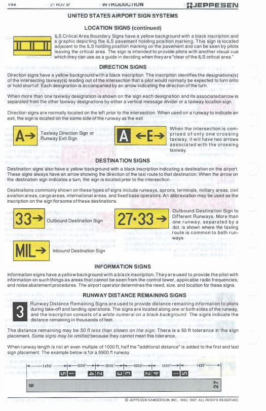
<11 NUV 97 IN I KUUUI,; l iON :PEPPESEN
U NITED STATES AIRPORT SIGN SYSTEMS
LOCATION SIGNS (continued)
ILS Critical Area Boundary Signs have a yellow background with a black inscription and a graphic depicting the ILS pavement holding position marking. This sign is located adjacent to the ILS holding position marking on the pavement and can be seen by pilots leaving the critical area. The sign is intended to provide pilots with another visual cue which they can use as a guide in deciding when they are "clear of the ILS critical area."
DIRECTION SIGNS
Direction signs have a yellow background with a black inscription. The inscription identifies the designations(s) of the intersecting taxiway(s) leading out of the intersection that a pilot would normally be expected to turn onto or hold short of. Each designation is accompanied by an arrow indicating the direction of the turn.
When more than one taxiway designation is shown on the sign each designation and its associated arrow is separated from the other taxiway designations by either a vertical message divider or a taxiway location sign.
Direction signs are normally located on the left prior to the intersection. When used on a runway to indicate an exit, the sign is located on the same side of the runway as the exit.
I A� I Taxiway Direction Sign or Runway Exit Sign
DESTINATION SIGNS
When the i ntersection is comp r i s e d o f o n l y o n e c r o s s i n g taxiway, it wi l l have two arrows associated wi th the cross ing taxiway.
Destination signs also have a yellow background with a black inscription indicating a destination on the airport. These signs always have an arrow showing the direction of the taxi route to that destination. When the arrow on the destination sign indicates a turn, the sign is located prior to the i ntersection.
Destinations commonly shown on these types of signs include runways, aprons, terminals, military areas, civil aviation areas, cargo areas, international areas, and fixed base operators. An abbreviation may be used as the inscription on the sign for some of these destinations. 13 3 � 1 Outbound Destination Sign
Outbound Destination Sign to Different Runways. More than one runwa y , se parated by a dot, is shown where the taxiing route is common to both runways. 1 MIL � 1 Inbound Destination Sign
INFORMATION SIGNS
Information signs have a yel low background with a black inscription. They are used to provide the pi lot with information on such things as areas that cannot be seen from the control tower, applicable radio frequencies, and noise abatement procedures. The airport operator determines the need, size, and location for these signs.
RUNWAY DISTANCE REMAINING SIGNS
Runway Distance Remaining Signs are used to provide distance remaining information to pilots during take-off and landing operations. The signs are located along one or both sides of the runway, and the inscription consists of a white numeral on a black background. The signs indicate the distance remaining in thousands of feet.
The distance remain ing may be 50 ft less than shown on the sign. There is a 50 It tolerance in the s ign placement. Some signs may be omitted because they cannot meet this tolerance.
When runway length is not an even multiple of 1 000 ft, half the "additional distance" is added to the first and last sign placement. The example below is for a 6900 ft runway.
1 1 450' 'I" 1000'-r--1000'-r--1000'-r-- IOOO' 'I" mll� elm! mJ&1 lam 111151
1 450'1
ICD � I
© JEPPESEN SANDERSON, INC .. 1992, 1997. ALL RIGHTS RESERVED.

INTRODUCTION JUl 1 7·92
UNITED STATES AIRPORT SIGN SYSTEMS EXAMPLES
Note: Genera l ly , s i gns w i l l be l i ghted i f the runway or taxiway on which they are i nsta l led i s l ighted. Holding pos i t ion s igns and any col located l ocat ion s igns w i l l be l ighted i f the runway for which they are insta l led i s l ighted even i f the taxiway on which they are instal led is unl ig hted.
I I I I I I I I I I I I I I
APPLICATION EXAMPLES FOR HOLDING POSITION SIGNS
1 5
os G> ..( I os I " I -: 0 I (J) I ...J I
-
1/ I I I I
J o-fImh �11 � � �--r
I I
I I
I I I «
/�-g I to I 0
I Q. I Q. I «
I I
\ \ ,
1 5 3
© JEPPESEN SANDERSON, INC., 1 992. AL L RIGHTS RESERVED.

1 5 4 JUL 17-92 INTRODUCTION
UNITED STATES AIRPORT SIGN SYSTEMS
EXAMPLES (cont inued)
nJEPPESEN
TAXIWAY ENTRANCE AT INTERSECTION OF TWO RUNWAYS
TAXIWAY ENTRANCE AT INTERSECTION OF TWO RUNWAY ENDS
mCDl" I'" gg
HOLDING POSITION SIGNS AT RUNWAY INTERSECTIONS
200' wide runway
Runway 27 used for land and hold short operations or used as a taxiway. Note holdline markings across runway for e i ther o f these t wo cases.
1 50 ' w iJe runway
A
STANDARD 4-WAY TAXIWAY INTERSECTION
STRAIGHT AHEAD TAXIWAY HAS DIRECTION CHANGE GREATER THAN 25°
Stra ight ahead Tax i w ay
NOTE: Or ientat ion of s i gns are f rom left to r ight in a c lockwise manner . Left turn signs are on the l e f t s ide of the locat ion s ign and r ight turn s igns are on the r ight s ide of the location sign.
AL --C----------J C c c
A
E xample of locat ion s ign shown on far s ide of intersect ion
l+-ctaAl'lc-+1 A l t ernate array of s igns shown to I CIAl'lC I+--+-__ i l l ustrate s ign +- -+ A or ientat ion when l ocat ion s ign not instal l ed
© JEPPESEN SANDERSON, INC., 1992. ALL RIGHTS RESERVED_

U.JEPPESEN
NOTE: Due to space l im i tations on th is drawing, some s igns may not be in the i r exact locations re lat ive to the runway or taxiway.
INTRODUCTION JUL 17·92
UNITED STATES AIRPORT SIGN SYSTEMS
EXAMPLES ( c on t i nued)
SIGNING EXAMPLES FOR A COMPLEX AIRPORT
9
" " c
ILS Cri t ical Area
_ _ _ _ _ _ _ _ _ _ L _ _
B
B
Apron
1+-3-+111 IINTLtl � c
Taxiway hold l ine mark ings instal led only where there is an operational need
1 55
© JEPPESEN SANDERSON, INC., 1992. ALL RIGHTS RESERVED.

1 56 JUL 1 7-92 INTRODUCTION JEPPESEN
UNITED STATES INSTRUMENT RUNWAY MARKINGS
Runway markings are white. Markings, exc l uding hold l ines and the runway des ignator mark i ng PRECISION INSTRUMENT RUNWAY (the runway number) are descr ibed below.
THRESHOLD MARKING
E ight longitud i nal s t r ipes of uniform dimensions arranged symmetrical l y about the runway center l ine. They are always 1 S0' long.
RUNWA Y CENTERLINE MARKINGS
A l ine of uniformly spaced str ipes and gaps located on the centerl ine of the runway. Str i pes are 1 20 ' l ong, gaps 80' long.
RUNWAY TOUCHDOWN ZONE MARKINGS AND FIXED DISTANCE MARKINGS
D i s t ance f rom approach end of runway to beg i n ning of t he mark i ngs
SOO'
1000'
1 500'
2000'
2S00'
3000'
Touchdown Zone. Three bars 7S' long on each side of the centerl ine. They are the beg i nning of the f ixed d istance markers. F ixed d istance markers are posit ioned SOO' apart.
Thousand Foot F i xed Distance Marker. One "heavy" bar on each side of the center l ine, 1 S0' long and 30' wide.
Two bars, 7S' long, on each s ide of the center l ine. Two bars, 75' long, on each s ide of the center l ine.
One bar, 7S' l ong, on each s ide of the center l ine. One bar, 7S' long, on each s ide of the center l ine .
SIDE STRIPE MARKING
Continuous str i pes located along each side of the runway to provide contrast w i t h the surrounding terrain and/or to de l ineate the ful l strength runway pavement areas. Maximum distance between the str ipes is 200'. Side stripe markings are normally provided only on preCision instrument rvnways.
For nonprecision instrument runways: TDZ markers are not provided. Fixed distance markers are provided only on runways 4000' or longer used by jet aircraft.
(!) t; � II: « :::;: w () z « � en o o w X u:
II: W � II: « :::;: w Z o N Z :;: o o :r: () :) o �
II: W � II: « :::;: o ..J o :r: en w II: :r: �
I I
w z �/ l-Z w ()
2 D
L
III
w c.. a: I-en w 0
Co 0 '"
© JEPPESEN SANDERSON, INC., 1992. ALL RIGHTS RESERVED.
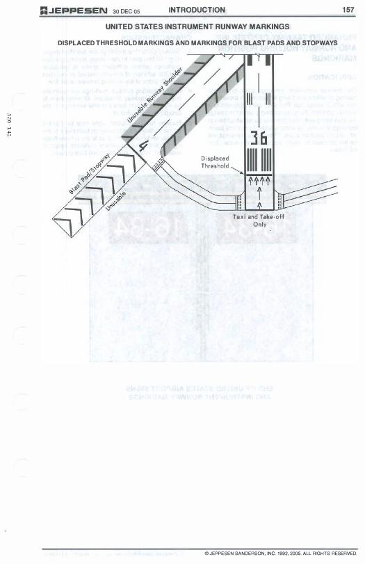
"..JEPPESEN 30 DEC 05 INTRODUCTION
UNITED STATES INSTRUMENT RUNWAY MARKINGS
DISPLACED THRESHOLD MARKINGS AND MARKINGS FOR BLAST PADS AND STOPWAYS
D i splaced Threshold
III I I�
1
] & 1111 1111 Taxi and Take-oil
Only
1 57
© JEPPESEN SANDERSON, INC. 1992, 2005. ALL RIGHTS RESERVED.

1 58 INTRODUCTION 30 DEC 05 G..JEPPESEN U NITED STATES INSTRUMENT RUNWAY MARKINGS
ENHANCED TAXIWAY CENTERLINE CHARACTERISTICS
AND RUNWAY HOLDING POSITION
MAR KINGS
APPLICATION
The taxiway centerline markings prior to runway holding positions are being enhanced to provide pilots with a visual cue that they are approaching a holding position. Runway holding position markings are also being extended onto the paved shoulders of taxiways and may be accompanied by surface painted holding position signs. These new markings will be the standard for many major airports in the United States.
a. Taxiway centerline markings are modified beginning 1 50 feet prior to the runway holding position markings (where sufficient space is available) with the addition of parallel dashed yellow lines on both sides of the existing taxiway centerline.
b. Existing holding position markings are extended onto paved taxiway shoulders allowing them to be visible to pilots from the side windows of the cockpit for many aircraft.
c. Runway holding position signs may be painted on the surface of the taxiway on both sides of the taxiway centerline leading up to the runway holding pOSition marking (where sufficient space is available), white numbers on red background.
- - - - - - - - - - - - -- - - - - - - - - - - - -
1 6-34 1 6-34
END OF UNITED STATES AIRPORT SIGNS AND INSTRUMENT RUNWAY MARKINGS
@JEPPESEN SANDERSON, INC. 2005. ALL RIGHTS RESERVED.
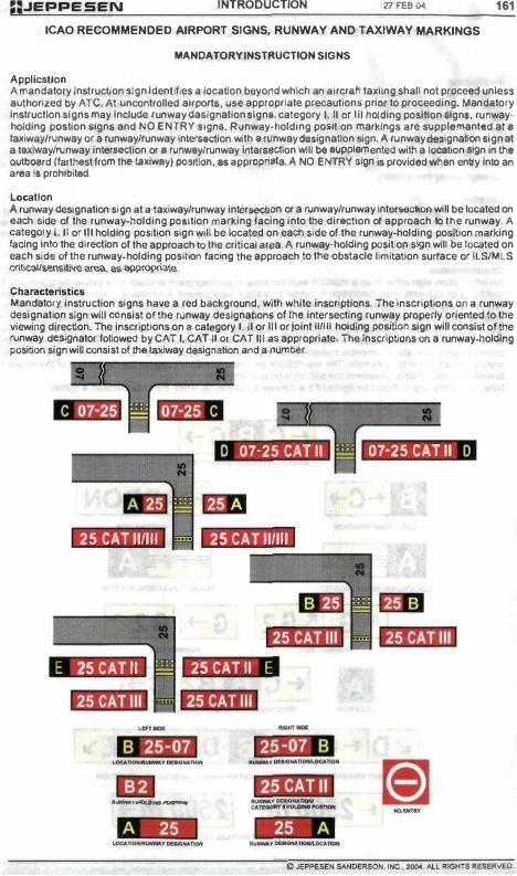
:PEPPESEN INTRODUCTION 21 FEB Col 16'
ICAO RECOMMENDED AIRPORT SIGNS, RUNWAY AND TAXIWAY MARKINGS
MANDATORY INSTRUCTION SIGNS
Application A mandatory Inatruction algn Identifies a locallon bayond which an aircr.ft taxiing shall not proceed unlen authorized by ATe. At uncontrolled airport., ua. appropriate precaution, prior to prOCeeding. Mand.tory Inltructlon signs may Include runway da,lgnation Ilgnf, category I, II Of IIll"Iolding position algn., ruoway· holding pOllion Ilgn. and NO ENTRY IIgn •. Runway-holding pOlltion markings are supplemanted al. la�iwaY/l1.Inway or a runway/runway inlerMclion with II runway ctetlgnallon aign. A runway �gnalion aign at a l8J(!waylNnway inlerMCtion or • fIM"IW.ylrunway IntarNclion will De aupplemenled willl a location ""n WI the outboard (farthest from thfllaxiway) potltion," appropriata. A NO ENTRY sign '- provlded....man entry InlO an area 1$ prOhibited.
Location A runway designation sign at a taxiway/runway inlersectiOn or a runway/runway intarHCtion wi� be located on uch lide of tile runway-holding pOlitlon marking facing into the direction of approach to tile runway. A category I. II or III holding position lign will be located on each side of the runway-holding position marking facing Into the direction 01 the approach to the critical area. A runway-holding position sign will bfllocated on each lidll of the runway-holding position facing the approach to the obatacle limitation surface or IlSlMlS criti-calIs.ensil.ive area, at; appropriatll.
Char.tlctaristic.s Mandatory instruction signs have a red b<ickground, with white inscriptions. The inscriptions OIl a runway designation sign will C(Inlist of the runway deSignation, of !tie Intersecting runway properly oriented to the viewing directlon. The inscriptions on II catagory I, II or III or joint 111111 holding polltion sign will consist of the runway designator lollowed by CAT I, CAT II Of CAT III a5 appl"opriate. The inscriptions on a runway-holding position sign will conaisl of the taxiway designation and a OWIber.
o 07-25 CAT II 07-25CATII D
25 CAT 11/111 25 CAT 11/111
.tm.1I1 ,tjd·iil E 25 CAT II 25CATII E
fjOjlti.1I1 .jOKi.1I1
-,.--- --
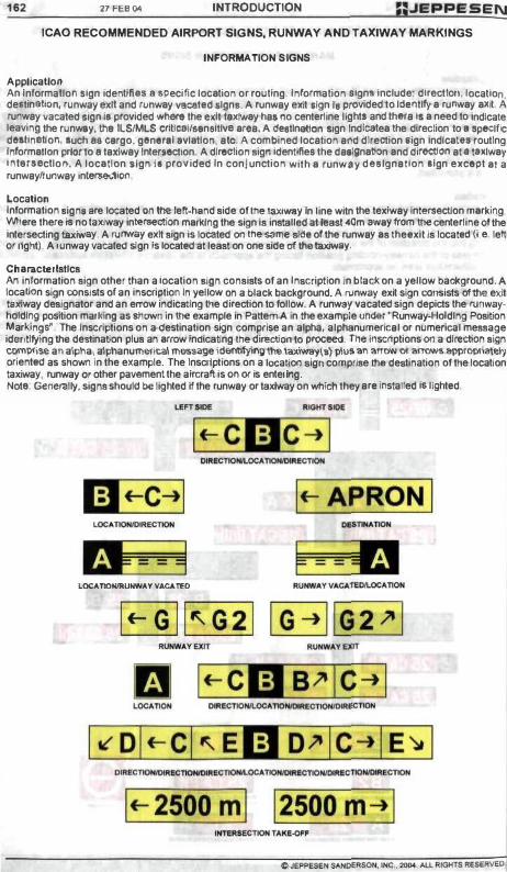
162 27 FEB 001 INTRODUCTION :;JEPPESEN ICAQ RECOMMENDED AIRPORT SIGNS, RUNWAY AND TAXIWAY MARKINGS
INFORMATION SIGNS
Application An Informallol'l Ilgn Identifl" I .pecillc loe.tion or routing. Informalion algn, Include: dlrectlori,locatlon, de.tinllilon, runway exll and n.mw.y Yl'Cllted Ilgnl. A runway exit .Ign I, provided to ldefltlfy. runw.y .�it, A runway �acated 11gn II provided where !he ult texiw.y hat no centerline Ughts and !hefa l,. need to Indicate leaving the runway, the IlSIMLS Ct1llcaIfHn.ltlv, .r.a. A tIe,tln.1ion ,Ign Ind�le.lhe direction to I 'pe<:lfic dlllln,lloll, luch •• c.ergo. glna'II,vl.tlon, atc. A combined location atld direction lign Indlc.t •• routing Inform.tlon prior to • taldway Inter,ectlon A direclion sign ldenllflea the daa!gn.11on .nd direetlon al' tII�lw.y ,oll,,,,cllo,,. A loc.llon .Ign I, provided In conjunction with . runw'y dnlgnatlon ,Ign except .Ia runwaylrunway Int8f'Mdiot1
Location Information lign •• re located 00 the left·hlnd side of the taxiway In line witn the texiway Intersection m.rking Vomere there is no taxiway inlerteCtion m.r1dng the sign is installed at ieaSl ",om ....... y from the centerline 01 the Intersecting taxiway. A runway exit sign Is located on the same si<le ofthe runway.s theexil is located (i.e. left 0( right). A runway vacated sign is located at least on one aide of the taJeiwlt)'.
Ch.racterlstlcs An information sign other than a location lign consists of an Inacription In black on a yellow background. A location sign consists of an inscriptioo in yellow on a black background. A runway exit sign COMists of the exit tllXiway designator and an errow indicating the direction to follow. A runw&)' vacated sign depicts the runway· holding position marlling as shown in the example in Pattem A in the example under "Runway·HoIdlng Position Marldngs'. The inscriptions on a destination sign comprise an alpha, alphanumerical or numerical message idl!lltifying the destination plus an .rrow indicating the direction to proceed. The II1scnplions 00 a direction sign C01TI):rIi\e an alpha, alphanument.a\ mnugeldentitylng the laxlway\.) plus an '!l'1)'H 1)1 BlT'lmll appropria\e\'j oriented as shown In the example. The inscriptions on a location ailJll comprise the deatination of the location laxtwaV, runway Of other pavement the aircraft Is 00 or Is entering. Notl: Generally, signs should be lighted if the runway or taxiway on whlch they are "'slaUed lalighted
If-APRONI
LOCATIONIItUIfWAV VAc.o. TEO
1f-2500 ml
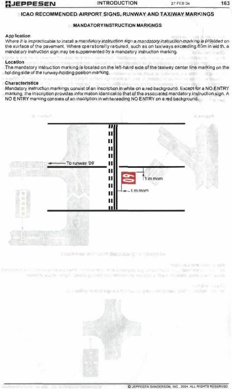
;;.JEPPESEN INTRODUCTION 21 FEB ()oI 163
ICAO RECOMMENDED AIRPORT SIGNS, RUNWAY AND TAXIWAY MARKINGS
MANDATORY INSTRUCTION MARKINGS
Application 'M'Iere it iJ: lll'lptJlct;e.bh! /0 JnsIalJ II mandalot)' lnsIruction tipi! II m.9!>OalOfY lm/rudioI'l mlil'king .. p«Nkled on the lurlace of tN! pavement. 'Nhere oper at ionally raquired, luch as on t.u:iwayl uceeding 80m In width. 8 mandato ry Inltruction sign may be wpplemented by II mandatory Inllruction marldng.
location The mantlatory inllrvctlon mart(ing II located on the left·ha.nct ,Ide 01 the 1I1dw.y centa! lloe matl(lng on the holding aI<Ie of 1M runway-holding potitloo mlOting.
ChaflilctertatlU M.ndatory inetn.lctlon mar1dn1j. contiS! of an Inscription in white on. red bIIckgroonc:l. Except lor a NO ENTRY metl(ing.ihe inSCription Pfovidaslnformation Idamicallo that oftha "$Socialed mandatory Inltrucllon l!gn. A NO ENTRY manung con s ilii. 01 an Inscription In white reading NO ENTRY on a red background.
" " " "
_To runway '09' " " :::J " t'mmnm
" " _lmmnm
"

21 FES 001 INTRODUCTION :;.JEPPESEN ICAO RECOMMENDED AIRPORT SIGNS, RUNWAY AND TAXIWAY MARKINGS
RUNWAY-HOLOING POsmON MARKINGS
Applle.tlon .nd LOCldon Rtif'I\IOIaY-hoiding position marking' .re located al runway holding position"
Charact.rlltlci At an Interllctlon of a ttJ.lway and iii non-precillon, non-In.lrl,lment or take-off runway or wh.r. a lingle Nnway-hoIdlr,g potItion Is prOVided at an Interllldion of a taxiway and a PflCltIon approach �tegOf)' I,ll, or III rl,lnwlY, Th. rlJf1way-holdlng po.�lon mlrkl� will bl llihown 1110'1 pattern A. Wher. two orthr .. rl,lnway· holding po.ltIOl1. Ire provid.d It .l,Ich an Intersection, the runway·holellng po.ITlon marking closer to the rl,lnway will bill shown IS In pattern A, atld the marklrlg.larther from Iha runway 1110'1 pattern B, Where a pattern B Nf'I'/O'.y·l'IoIdlng position marking exceed, 80m In length, the term CAT II orCAT Illes epp!'OSlri'" win btl mlrllad on th. 'I,Irtle. at the ands of the I\Jnway·holdlng position mal1ling. The runway-holding po.lI1on marking disptayed .t a runwayirul"lWlly Intersection will be perpendicular to tne CMllfline of the runway forming pari ollhe slandard taxiroute. The runway-holding position matldng wi� be IhOwn as in pattern B.
p.ttem A Pattern B
INTERMEDIATE HOLDING POSmON MARKINGS
AppllCltlon .nd Loutlon AIl intennediate holding poaiIion marking is displayed at an Intersection 01 two paved taxiways. II ia positioned acros.s the taJUWay ooincidllr"ll with a stop bar or intermediate holding position ligllts. where provided.
Characteristics An Intermediate holding position m8l1Ung consist. of a single brok8ll yellow line.
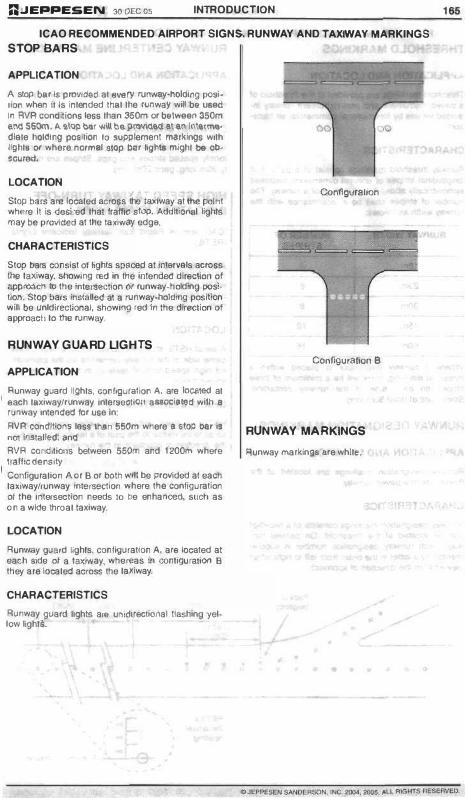
GJEPPE&EN 300ECOS INTRODUCTION
ICAO RECOMMENDED AIRPORT SIGNS. RUNWAY AND TAXIWAY MARKINGS STOP BARS
APPLICATION
A stop bar it provided at _rv runway-llokijng positioo when II Is Intended tnat the .ooway wiM � UIIed trl AVA conditioos less than 350m or �Iweeo 350m aM sSOrn.'" al':lp bl!.! w\l bep�a\ 111\ 1!1\i1r\M' dlate hokjjng poft�iOn to IJUpPlemenl mllr�jngs wIth 19htB or where normal Slop IlIIr �gtU might be ab· � ....
LOCATION
Slop hars are located a<:ross the Ia.-/way at lhfI poin t where II is OOSIted thai lralllC slop. AddrtiOl'l8I lights may he proviOOd at the laxiw(l)' edge.
CHARACTERISTICS
Stop hars consist of �ghts sPlIced at intervals across the taxiway. sOOwrng led in the inlended directioo of approoctllO the inte'sacllon or runway-holding posi· tloo. Stop hars ,"stalled at a runway-ho�ng posifioo will be unldiractlonat. showIng ,ed fn the dlraction 01 approacil to the runway.
RUNWAY GUARD LIGHTS
APPLICATION
Runway guard �ghts. configuration A. ale located at each taxiway/runway IntersectiOf1 auoclllted with a runway Intended lor use In:
RVR condI!lons las. than 550m where II stop btl. it not IMtalJe.d: lind
AVR COndrtlOflS between 55Dm and t200m where tmftic density IS madium or low.
Coo1iguration A or B or both Will he provided at each taxIway/runway interseclion where the configuration 01 the Intersection needs 10 be enhanced. sl/ct1 as o n a wkle throat taxiway.
LOCATION
Runway gua.d Hghts. configuration A. ale located at ea<:h side of a taJCiway. wher!!as In oonl19ulall00 B they are klcated across the taKiway.
CHARACTERISTICS
Runway guard �ghts al(l uflldlrectiOl1alllashing yel· low lights.
00
Configuration A
ConfigurallOf1 B
RUNWAY MARKINGS
Runway marlcingt .. re white.
•
16.

'" INTRODUCTION 300ECO!l AJI!!PPI!!IiEN
ICAO RECOMMENDED AIRPORT SIGNS, RUNWAY AND TAXIWAY MARKINGS
THRESHOLD MARKINGS RUNWAY CENTERLINE MARKINGS
APPLICATION AND L.OCATION
Thrashold marl(lngs are proYicl&d at tile threshold 01 a paved Inltrl,lment and !'Ion·llIstruman! runway In· tel'lClod lor U811 by mtllrna�o!'\81 commercial air trans· P""
CHARACTERISTICS
Runway threshold marklngs consist 01 a paltern 01 long�udll\Bl strIPIIS of undorm dlmallslona disposed symmetrically abouIlhe �llIar1ine 0111 runway. The numoor of stripes maa 00 In accordarICe with the ,lIflway width 8S follows:
RUNWAY WIOTH NUMBER OF STRIPES
'6m ,
23m ,
"'" ,
<om "
""" "
Wher, a runway de5lgrl81Of Is piKed within a threshold mllri<.,"\!, the'a w�1 be II minimum althree &Uipe5 OIl e.i;h stete 01 the runway centerline. Stripes are alleast 30m long .
RUNWAY DESIGNATION MARKINGS
APPLICATION AND LOCATION
RurtWay des�natiOn markIngs are located a! the thresholds 01 a pave<! runway,
CHARACTERISTICS
Aunway deSIgnation markings consists of a two-<;ligit number tocated at the threshold. On parallel run· ways eact1 runway designation number is supple· mented by a letter In the order from lell to righl when viewed from the direction of approach.
• •
• •
• • • • • •
• •
•
PoonlO! '''''''''''
S • .\ • • •
•
• •
APPUCATION AND LOCATION
A I1.IIIWlIY �1,"1irM11 marklllg 18 pro.,.;Qe.d 01'1 II P/IVed runway IIlnrIG tile centeriine.
CHARACTERISTICS
Runway centarina ma,1ungs consist at. line of uoi. Iorml)l spaced .tnpes and gap •. Strlpea ere normat· Iy 30m to"9, gaps 20m long.
HIGH SPEED TAXIWAY TURN�OFF INDICATOR LIGHTS (HSTIL)
ICAO term Is AapKl Exil Taxiway Indicator Ligh,s (RElIL)
APPUCATION
HSTIL should be puwided on a runway inl(!mla<j lor use 11'1 AVR eonditiorls less ItuUl 350m and/or wher'! traffic d&nsily is tt&avy.
LOCATION
A sel of HSTIL shall be located on Itle rurtWay on ttll! same side olille runway centerline as the assoclat· ed high speed turn·oll ta�1wilY. In the configullItioo ahown below
CHARACTERISTICS
HSTIL ille II�ed unidirectional yellow lights, aligned so as 10 be visible to the pilol Of a landIng ",plane 11'1 tha dIrection 01 approach to the runway.
(328') "0,,,
�) •
I , : RET'LI 2m lateral �-
(328') (328') , ""'" ""'"
1 -' , ,
, , • • • • 0 , �o�/ ---
- - --, /- - - . ' - j' , . ... ' ,
, " , ... , .
, , , -
, ' ,
" 0 I"",.l' Ru"""'Yc&""'�"'"
•

;;JEPPESEN IN I RODUCTION 21 FEB I)( ltH
ICAO RECOMMENDED AIRPORT SIGNS. RUNWAY AND TAXIWAY MARKINGS
RUNWAY TOUCHDOWN ZONE MARKINGS
A.pp/lC�lflon A touchdowl1 zone mal1<.1ng II provided III Ihe toUChdown zone of a peved precision eppwoch runway and and non.precislon approaeh runway or non· Instrument runway wherl! additional Identification of the touchdown lOOf! Is required
LOCitlon and Ch.rutan,tlet A touchdown zone marking shall conlill of pell. 01 re<:timgular marking. Iymmetrically disposed abOut the runway eente�l� �th the number 01 palr, relaled 10 the landlflg distance ava�able (lOA) A 100000000wn lOl'lfl markirlg ,hall conform to "ther 01 the two Noway panernl $hown below
RUNWAY AIMING POINT MARKINGS
Application An alml11g point marking Will be provided at eaCh approach end 01 a paved Instrument or non·lnstrument runway
LOClllon and Ch,rattan,tlc, An IJiming poim marlrmg eon.!i.!l.! of IWO eon8pic�S stl/pIS Inconformity with/he dimen.!ion.! shewn for the ruoway palle,.,s in !tie example shown uncler "Ruflway Touchdown Zone and Aiming POint Markings"
C jEPPfSEN SMloE�SON, I NC :10)< ,.ll RIGH TS �ESE"""O
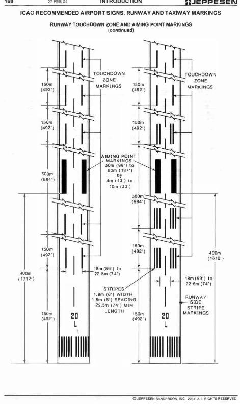
". 21 FEll 0" INTRODUCTION ,PEPPESEN ICAQ RECOMMENDED AIRPORT SIGNS, RUNWAY AND TAXIWAY MARKINGS
"OOm ( 1312')
RUNWAY TOUCHOQWN ZONE AND AIMING POINT MARKINGS (contlnu&d)
-
.J. (492')
150m (492')
",. (1184')
I-
" . (492')
150m (492')
.... ,
I
I I
r
,J UCHDOWN
ZONE
RKINGS r "'
r
-1::���;JL;TOUCHOOWN ZONE
MARKIHOS
IMINO PO'N.�,t-:::;r��;dl
IV MARKINGS 30m (9S') 10
60m11S7')
" 411\ (13') 10
10m (33')
I ; I
I 20 L I
1111111111
r
r-�8m ( 22.5
59') 10 m(H')
1.8m 1.5m
(8') WIDTH
(5') SPACING
m (74') MIM
LENGTH 22.5
150m (492') 20
L
RUNWAY
4DOm (1312')
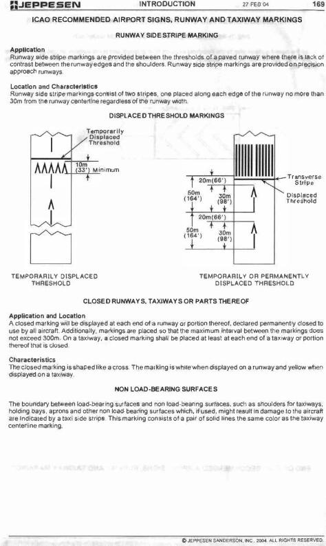
n.JEPPESEN INTRODUCTION 27FE8 � 169
ICAO RECOMMENDED AIRPORT SIGNS, RUNWAY AND TAXIWAY MARKINGS
RUNWAY SIDE STRIPE MARKING
AppUeatlon Runway &ide stripe markings are provided between Ihe Ihresholds ola paved runwa� Wher, Iher, I. lad<. of contrast be1ween the runway edges and !he IIhoolde,., Runway � wipe markings are provided on ptecltlon approaeh runways,
LoeatJon and Ch.l1Ieterlltlel Runway Side stripe marlungl coneist 01 two '!ripes, one placed alongald1 edge 01 the f\lnwuy no more Ihan 30m from the runway cenllf1lne regardleas 0I1t1e runway widtti
� T.m
I l/P"
",
• AAAAA )g:r Mi
I +
A I
o TEMPORARILY DISPLACED
THRESHOLD
DISPLACED THRESHOLD MARKINGS
nimum Transversa
Stripe
Dlsplacld Thrnhoold
TEMPORARILY OR PERMANENTLV DISPLACED THRESHOLD
CLOSED RUNWAYS, TAXIWAYS OR PARTS THEREOF
Applieatlon and Location A closed marking will be displayed at each end 01. runway 1)1" portion thereol, declared permanently dosed to use by all aircraft. AddItionally. marl<.ings are placed &0 thatlhe maximum int&fYal between the marl<.ings does not exceed 300m. On a taxiway. a elosed marking shall be placed at least at each end 01 a taxiway or portion tl1ereolihat is closed.
Charaeteristies The closed marl<.ing is shaped like a cross. The marking is wMe when displayed on a runway and yellow when displayed on a taxiway
NON LOAD-BEARING SURFACES
The boundary between load-bearing r;urfaees and non load-bearing surfaces. sud"i as shoulders for taxiways. holding bays, aprons and other non !o.ad·bearing surfaces which, II used, might rellUlt In damage to Ihti aircraft Ine lndicated by a taxi side stripe_ This marking conlist. of a pair of solid lines the same color as the taxiway centertine marking.

170 17 FEB ()oI INTRODUCTION :;.JEPPESEN ICAO RECOMMENDED AIRPORT SIGNS, RUNWAY AND TAXIWAY MARKINGS
PRE·THRESHOLD AREA MARKING (CHEVRON MARKING)
When the pa�ad wrtace prior to the thrHhold uceeds SOm in length and Is not luililble few UN by aircraft, the IIntlre length will btl marlled with. chevron mal'lling (preferably yellow) pointing In the dirflCtion olllle runway thre&hoid.
THRESHOLD
- PRE·THRESHOLDAR EA -
) )
( > RUNWAY CENTERLlNI:
END OF ICAO RECOMMENDED AIRPORT SIGNS, RUNWAY AND TAXIWAY MARKINGS
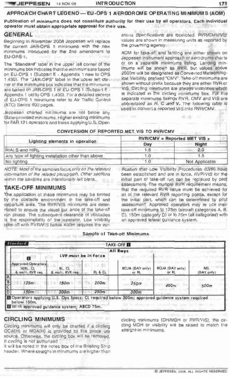
""'!'I!IIJJEPPESEN 1 4NCl'I08 INTRODUCTION 171 APPROACH CHART LEGE ND -EU-OPS 1 AERODROME OPERATING MINIMUMS (AOM)
PubH,,"tlon 01 mi n imum. doe. not con.lltut. a uthor ity lor their u ... by .U op er ator •. E .. ch Individual op era lor mu.t obt .. ln .pproprlilt .. epprov .. llor their u ••.
GENERAL Beginning irI NOvember 2008 Jeppesel1 wm rep l_ IhI! current JAR-oPS I min imums wrth tne new mlnlmuma Introduoe<l bY the 2nd amendmeot to EU·OPS I. Tne -SI"nd,rd" label In !he upper kill corner ot the minimums DOX in<Ucatea thallt1e mlmmumsare ba&e<:l 00 EU'OPS I (Subpart E - Appendix 1 n_ lo OPS I .30). The -JAA·OPS· la bel In the upper lell corner of the mon,mums bOx Indicates that ttle mln,murns we based O<l JAR-OPS 1 Of EU-OPS 1 (Su bpa,t e -Appendix I old to OPS 1.430). for a delai !ed excerpt 01 EU·OPS t mlmmums refer to Air Trallic Cootrol (ATC) Series 600 pages.
.)(!ppeserl charted rnlrllmums 8'0 nO! below arly Stale-provided minimum s. Higher existing minimums lor FAR 12t Gp(!ralOrs and thos6 appl ying u.s. Oper-
(I!lOrlS Specif�110<l8 are IoolrloloO. RVAlCMVNtS valuo5 alo $hOwn In mee5urlng Url�S as reported by the OOll6rnlng egoney.
AOM lor lake-olf end lafl<llng ere ellhe. shown on Jeppesen 10Slrument Elpptoacn or aerodrome challs Of on a Mp arale minimums IIstlog. Landrog min· Imums win be showo as RVR, but valves above 2000m will be deslgoalod as COIWetled MeleorologIr;aJ Vis�lIily. prel/ll;ed "eMV'". Take-olt minimums are ShOwn without prellx because they are either RVA or VtS ClrcHng mln ..... ums are always v;5IOilJtles-whlctl Is lndK:aled in the circling minimums box. For lt1e separate minimums Ustlfl\ls AVA. CMV and VIS are ilWev;III6(/ liS R. C /lfId V. 7116 /allowing IlItIIe i$ used 10 convert a reperled VIS into RVRlCMV .
CONVERSION Of REPORTED MET VIS TO RVR/CMV
Lighting elements In operation
HIAlS and HI�L
A al ii h\l
No r h �n Installation o1t\er than IIbtwtI
NOTE. Mesr 01 r/le samples locus 0fII)' Ctl the rel6Vllnt mol:)rmaoon of rIIfl relared paragrupfl. Odter sectJbns wlrhm Ihe S8mP/e. life intentionally left Ol8rtk. TAKE-OFF MINIMUMS The appIlcallon 01 these mlnlm�ms may be limked Ill' ttle obstacle envlrCtlmet"lt iO tile ta�,,·otf and (l&paflur. afes. The RVANIS minimums a,1I deter· mlneol to ensu'e the visual guidance 01 lhe take-ott run phase. The subsequent clearance at ObStllCIeG ill the responsibility 01 the operator. Low visi bility take-olt" with AVRNIS below 400m requires the vel-
RVRI CMV . Re o . .. '0 '0
orted M ET VIS x Nt ht
'.0 "
Not A licable
IfIcaUOn tIlal Low VI/iH)ll lty Procedures (LVP) have been established anOafll In fofce. R'/RNIS IrX IhtI Inillal part 01 IIIkG-olI run can � replaced by Plio! assessment. The multiple AVA requlremem means, that lhe required RVA vakle mwt be IIChkMld 101 aU 01 Ihe ,elevant RVR repor llng poInt8. except lor the In�,al pan, wnlch can be delermll'led by pilot assessment. Approved operators may re dllCB their taka·ol1 minimums 10 125m (alreral! categori&s A, B, C). 150m (CIl.I89OI"Y 0) or 10 75m (all categories) with an appfoved lateral guklal"\ce syslem.
Sample 01 Teke-oll Minimum.
LV' Must be In f"r�.
""" , .... ,,""
CIRCLING MINIMUMS Clrcnng minimum. WI. only be ehartad II II cfrcllng OCA(H) or M()A(H) I. provlOed by lt1e procedure lOurce. 0\1"18"""". tne circling box wiU be remoV8d. It circ�n g III noIlutnorll.ed by the procedule source. � will be noted In the notllS box of lI1e Briefing Strip headef Where atralghHn mlnomumlare higher lI1an
,,,,.,, "'''' ""'.,,
elrcling minimums (OHIMOH or RVRNIS). the elrcling MOH or vl8lbH�y will be raised 10 malch lI1e Inra�hHn ml!1imums.

172 INTRODUCTION 14 NC1\! OIl �JEPPESEN
APPROACH CHART LEGEND - EU-OPS 1 AE RODROME OPERATING MINIMUMS (AOM)
NON·PRECISION APPROACH MINIMUMS AND CHART PROFILE VIEW Aecortll!'IQ 10 me EU-OPS Iltqllll'amerl!l. aU r\Q(l-PrueiSkln BpprOllC/'les shall !)e llown ulliflg the continuous (laKIn! tln., approaCh (CDFA) technlClll8 with decillion altltude (height), and the missed approach shall be executed wheo reachlog the D"lH) or the missed approach point (MAP). whicheverOCCUIS 11111.
The IIIleflll parI of !he missed approach procedure must be l\own Via the MAP unless lItatod olherwise lf1 the procedure. N{lrmal'V only COFA minimums afe snown. These are klenti!ied by !he vee 01 II OA(M), JePP9Mtl does not include an add� when pubhhlrlg II CA(H) lor a COFA non-p.ecia/on approact\ Non-CDFA mlnlm\Jms are 6hown if1 ex�1orIa1 cises 81'1(1 k:lenl,lie(l DY an MDA(Hj.
Sample of Non-precision Minimums (eOFA)
SfflAIGtfl· ! N l ANDING f/;WY 07
'>A{", 680'1419') • M f- -A
• !I'I� 1500m 11'/. /50Om
C 1M! 16� 1M! '000...
,
snAI�f- IN LANDING �W'f O '
o"'f",680'(4'':'''' ""'III"! 680'(419") At our
A
• IIVl 1:50am 'VII 1:50Om IIVl 1800m
C .VII /6oOm 1W'J()(J0m ..... ,000m
,
Thl! pro!He dapoclion will be modifoed \0 show the conIInIiOUS de9Cflflt on final approach. Soure.,..pubIished mimmum altitudf!s will be shown as SIIgmenl mini· mum altitudas in Iha profile {grey shadad bo�). These minimum attau des are Iypically provided lor obstacle cleamroca and mUSI nor b!I 00101100 10 remain clear of obstacles 0( terrain.
If nor published by \he procedure $OU"', a table depicting DME vs altitude, dislar1C$ vs altiludtt. o r liming va all,jU(!e will b G calculat(ld by Jewesen and shown above Ihe prof tie view The liming table lflclu<IQs Ii1e �I angle, the FAF and Ille allilude 81thll FAF. AIllludes a.e calcUIaIl:ld lor 20. 40, 60. 80 and 1008 f.om FAF and ale based on o;p8eds Of 90, 120, 140. 160 and 180kl. Only a!tiludes ab<:I...e !he dedalon allilude are provided
• . , f- -CM�'J1OOm
CM�UOOm
Sample 01 timing vs altitude table
lG lctr: 5000'
]_60� 20, <0, ", BO, 100s 90 kr -4.10' "620' 4430 ' "2-40' 4050'
120 kr 4150' 4490' 42"0' 398O' 313O'
1-(0 kr "'10' "410' "110' 3120' 3520'
160 kr 466O' <1320' 3980' 3650'
lao kr 4620' 4240' 3160'
Where COFA m ..... imums '"8 Iihown, the prolile w�\ be modified 10 deplc' ttle OO(l1\nuouS delleenl. The mined approact1 pull·up alrow � shown alma pOlril where the decision nelghl Is raact'led. There Is no level segment deplclO<l prior to the MAP, and me MAP Is shown as putlhshed by,he procedure source

-."... JEP PESEN 14 NCN 118 INTRODucnON 173 APPROACH CHART LEGEND _ EU-oPS 1 AERODROME OPERATING MINIMUMS (AOM)
INJOAoll ALtIlU)£
A r 2930'
'.0 3620
[TCH SO"
' .0 3940'
05.0 I �
...... � .•...
In exceplional cases it may be necessary 10 IllChide CDFA and non-COFA mtnimums. Wh8fe Itlis OC¢UfS, a level segmem is shown prior 10 lhe miss.ed approach poir1l and 1h6 pull·up afTOW Is shown allhe MAP.
' .0 ' .0
��:r�� __ S:9�O;O� ' �������J:�-"��
(TCH 52'1 - -
CAT' PRECISION AND APV APPROACH MINIMUMS All AVA of less man 150m may tie used under 1!"Ie eond�lons 8. 10 d. sllown below (Full COlumn). 0111· e!Wlse lhe AVA Is timiled 10 750m Of above (limited COlumn).
a. CAT I operations 10 runways wilh FALS and TOZ and CL and with deetsion heighl 01 200ft or
b. CAT I operaHons!O runways with FALS oot without TOZ and/or CL when using an approved HUOLS or an equlvalenl approved system or
c. CAT I operations 10 runways with FALS but with
oul TOZ and/Of CL when condu-clli'lg a coupled or Ilighl·dlreclor·llown approach to a decision height not less than 200tI Dr
d. APV to runways with FALS and TOZ and CL when USWlg an approved HUD. but 'lOt below AVA 600m.
10.0
2 Min
2 Min
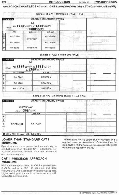
174 INTAODUCTION l Uo O\l08 �JEPPE5EN
APPROACH CHART lEGEND - EU·OPS 1 AERODROME OPERATING MINIMUMS (ADM)
SlImp ls of CAT t Minimum. {FALS .. ell -
'"
a"IH} A,,·I2S8'(200', C 'I� � U'(260') D , 138"��o'
• • - --•
""�$$Om IIY� 1200m • .".1 150m
, 1M1600m IMIISOOm -
0 IMIBOOm IMIBOCm 1M1150i1m
Sample 01 CAT I Minimums (IALS)
'"
"",H, As:1258'(200'} C:1318'(260') 0: 138a'(.J�o·1
-A • .>n75Om lV_,Mam
, ""�8(JOm IMIIJOOm
0 IVI 1100m IIVt/SOOrn
SlImple 01 APV MInimum. {FALS .. TOZ .. ell
.-"
lNAV/VNAY 1M/",1308'/150'}
• • , ."'75OmB iI'I.,JOOm
0 DWI," T01, (1 ""oS HUD: IIVR b OOm
LOWER THAN STANDARD CAT I MINIMUMS Operators must be approved by their aulhorlty t o conduct lowe, than standard CAT I operabOlls. For approved operators. lallo<ed charts will DEI created on customer reqUil5t.
CAT II PRECISION APPROACH MINIMUMS Minimums 11111 IIppUcllOIe to EU,OPS approved oper· atol1l 11$ weM 85 to FAR t2t operators lind those IIPPlylng U.S OP6ratlons Sp!H:lfications (OpsSpecs). Higher II�lstlng minimums 1(1 accordance with U S. OpsSpeee ere footnol&d.
-
Tile minimum AVA Is 300m. But lor category 0 it IS required tocol'lduct an autoland. Otherwise, the m,nImum AVR is 350m: how_r, tfIls Yaloo;s not charted on standard Jeppesen charts.

� JEPPESEN 14N0108 INTRODUCTION 175
APPROACH CHART LEGEND _ EU-OPS 1 AERODROME OPERATING MINIMUMS (AOM)
Sample 0' CAT 11 Minlmuml
nRAIGWT,lN lANDING R WV 04 (AT If IlS
AICD t ... CH RA 141' RA 184'
D.o(HJ 855'(loo') D.o(HI817' 111'
�V1! JOOm D 11V11400m
D ep..atoro applVlng U,S. Op. $p«.: ... utol ...... or HGS 'M\Ulr..! below RVR 350m,
OTHER THAN STANDARD CAT I I PRECISION APPROACH MINIMUMS These minimums will only be publishe<j ij the proce· dure i$ approv&d lor their use by the aeroorome's Civil Aviation Aulhorrty. Charling is similar 10 slandard CAT
n minimums but IflCIudes COlumns for condijions with and wllhoutllghts. An RVR 01 400m or below C9J1 only be used !I CL are availablo. Whero the higher value 01 450m is shown iI1lho oox. the lower value, which '&qulres Cl. is added as foolnote.
Sample of Other Thlln Standard CAT II Mlnlmuml (FALS + CL)
STR ... IGHT · IN lANDING RWY 04 ABCD
CAT IIILS lACH
RA 141' RA 184' o,oIH}855'OOO'} {)A1"1871'Olr
,
1IVIt450ma M700m 1I;Y.450m M700m
a Will'! (L: CAT A , B & ( RVR 3$Om, CAT 0 RVR .0Om
Sample 01 Other Than Standard CAT II Mlnlmuml (IALS)
STRAIGHT- IN LANDI NG RWY 04 AICD
CAT II ILS LACFT RA 1.41' RA 184'
0"(H,855 '(lDO') ""(H/811'(I12'
M450m 1M 700m
CAT III PRECISION APPROACH / MINIMUMS CAT III minimums Ire only Charted on 13,Iorlld char's or on m, .. ..rllne Chari $&fle$ (CAO) Tfle (leplcllon d&pands on the customer's approved fTllnlmums (a"CflIIt category or alrcratllype).
" ,
!1V11500m 1M! 700m
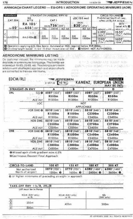
176 INTRODUCTION �JEPPESEN
APPROACH CHART LEGEND - EU'()PS 1 AERODROME OPERATING MINIMUMS (AOM)
STRAIGHT -IN LANDING RWY 16 CJfI.CLE.1O. l AN��_ '" tOC (GS 0",1 Prohibit"! South 01 . ", y ,
CAT IUA CA," CAn wlwn tFllj_IIA ..:1ive
RA 105' ,. ,. WI. 1/.0 .. 756" 1)( r 830'12' , ",,50' o .. r�! 656 �loo· � . local "TS II
,-, • �, " , ,,, MA4j�) _VIJ_ ""' .. (H,_VII_ '" 1 1 90' 1530' c ('�4') �NOOm (9'14'/ Uoo..,
IVI200", .... �JOOma � �, � � � "'m "Om ' ''''''' ,- ,,- 1290' 1600' , '" (7J4,)J600m (I044'l6(X)m
D Ope ••• o," applyl l'lO u.s. Opl Sp.CI: ...... 'ollO'ld 0( I1GS • ...,. 1,.., below 1IV11 3SOm. o Circling .... Ight D.,.d on ,wy 10 dllpl th, .... . Iev of 556'. II NIGHT: 001 AUHIOlllztO.
AERODROME MINIMUMS LISTING On customer request the mif1lmums may be made available on a minimums liSting page. The listings are irldexed as 10-9S. 2(HIS. elc. This listing is an k1lerim SQiulX>n until al! afflK;ted approach alld aifport chints are OOfMlrted 10 the new minimums.
EDCM/RLI �JEF"F"E5EN
2 1 � ' OS [@]]) KAMENZ,
" OContil'>UOUi Descent Flna! ApprO&Ct.
0 0' hlgt..r ml"lmum, precedlnv ",eight-I" approach
TAKE.OfF RWY I ILIR 29l/R
250m AOOm "'m

-=>!I!I!!III'JEPPESEN l ' l¥:N 011 INTRODUCTION
APPROACH CHART LEGEND - EU·OPS 1 AERODROME OPERATING MINIMUMS (AOM)
DEPICTION OF EU-OPS AOM IN CASE OF EXISTING STATE MINIMUMS It Sliue minimums aflll oHieial� publlthed, the depic· Hon ot AOM may dittuf from 1h4' Slar-dard depiclion where all values are e�pressed as AVA or eMV.
II. II AVRlCMV and VIS are charted tog&tMr, the AVA vatue � compulSOry. Ii no AVA Is reported. the VIS hilS to be uS&d wlll"tOul CO<1verslOO.
b No prefiJ Is charted II AVRlCMV andVIS is Ide ... •
tlcal. The reported AVR Is compulsory. If no RVA Is reported. lI"te VIS hils 10 be used witl"l· oul OOl'lVlllrsion.
c. II only VIS is charled, !hili VIS has to be used wllhout conversion.
I
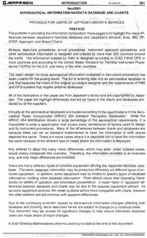
:;JI!PPI!SEN INTRODUCTION 22 JUN () l 2., Nav2OQ1
AERONAUTICAL INFORMATION NAVDATA DATABASE AND CHARTS
PROVIDED FOR USERS OF JEPPESEN NAVDATA SERVICES
PREFACE The purpose: In providing ttle information contained In ttlese pages Is to highlight the major dif· ferences between Jeppesen's NavDala database and Jeppesen's Enroote, Area, SIO, DP, STAR, Approach, and Airport Charts.
Airways, departure procedures. arrival procedures, Instrum&nt approach procedures, and other aeronautical information is designed and created by more than 220 countries around the wOrid. The information created by them is designed according to ICAO PANS OPS in most countries and according to the United States Standard for Terminal Instrument Proce· dures (TERPs) for the U.S. Bnd many 01 the other countries.
The basic design for most aeronautical information contained in instrument procedures has been created for the analog world. The art of entering data Into an aeronautical database is one that balances the intent 01 the original procedure designer and the requirements 01 FMS and GPS systems that require airborne databases.
All of the illustrations in this paper are from Jeppesen's library and are copyrighted by Jeppesen. The paper wiff highlighf differences that wiU be found in Ihe charts and databases produced by all the suppliers.
Virtually all the aeronautical databases afe loaded according 10 the sp$Cifications In the Aeronautical Radio, Incorporated (ARINC) 424 standard "Navigation Databases.' While the ARINC 424 �Iflcation covers a large percentage of the aeronaullcal requirements, II Is Impossible 10 write a specification that covers every combination of factors used to design and fly instrument procedures. Many 01 the differences between charts and databases are because there can be no standard implemented to have the Information In both places depicted the same. There ara some cases where It Is desirable not to have the information the same because of the different type of media where the information Is displayed.
Any attempt to detail the many minor differences, which may arise under Isolated cases, would unduly complicate this overview. Therefore, the information provided Is an overview only, and only major differences are included.
There are many dffferent types of avionics equipment utifizing the Jeppesen NavData database. The same database information may be presented differently on different types of airborne equipment In addition, some equipment may be limited to specific types of database information, omitting other database information. Pilots should check their Operating Handbooks for details of operation and information presentation. A major factor In "apparent" differences between database and charts may be due to the avionics equipment utilized. As avionics equipment evolves, th8 newer systems will be more compatible with charts, however the older systems will still continue with apparent diffefeflCBs.
Due to the continuing evolution caused by 8eronautlcal information changes affecting both database and charting, items described herein are subjeCt to change on a continual basis. this document may be revised tor significant changes to help ensure Interested database users are made aware ot major changes.
A brief Glossary/Abbreviations oflerm5 used Is provided at the end of this document.
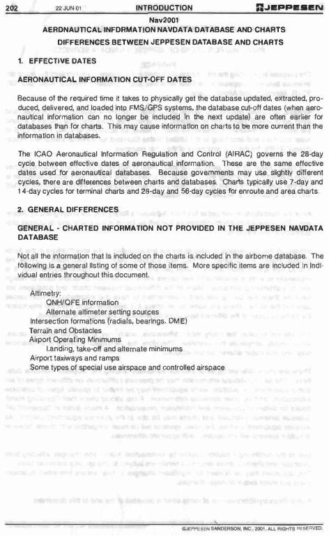
202 22 JON 01 INTRODUCTION R.JBPPB.I!N
N.v2001 AERDNAUnCAl.. lNFDRMATlON NAVDATA DATABASE AND CHARTS
DIFFERENCES BETWEEN JEPPESEN DATABASE AND CHARTS
1. EFFECTIVE OATES
AERONAUTICAL INFORMATION CUT-OFF DATES
Because 01 the required lime II takes to physically get the database updated, extracted, produced, delivered, and loaded Inlo FMS/GPS systems. the database cut-off dales (when aeronautical Information can no longer be Included In the next update) are often earlier for databases than for charts. This may cause information on charts to be more current than the information In databases.
The ICAO Aeronautical Informalion Regulation and Control (AI RAG) governs the 28-day cycle between effective dales of aeronautical information. These are the same effective datas used for aeronautical databases. Because governments may use slightly different cycles, there afe differences between charts and databases. Charts typically use 7-day and 1 4-day cycles for terminal charts and 2S-day and 56-day cycles for enroute and area charts.
2. GENERAL. DIFFERENCES
GENERAL. - CHARTED INFORMATION NOT PROVIDED IN THE JEPPESEN NAVDATA DATABASE
Not all the Information that Is Included on the charts Is Included In the aIrborne database. The fOllowing Is a general llsllng of some of those items. More specific Items are Included In Indl· viduel entries throughout this document,
Altimetry: QNHlQFE Information Alternate altimeter setting sources
Intersection formations (radials, bearings, OM E) Terrain and Obstacles Airport Operating Minimums
landing. lake-off and alternate minimums Airport taXiways and ramps Some types of special use airspace and controlled airspace
> IlJEPPESEN SAHOERSON . He .• 200 , . AU AlGt<TS AESERV!;[) .

n.JEPPESEN INTROOUCTION 22 JUN 0 1 2.3 Nav2001
AERONAUTICAL INFORMATION NAVDATA DATABASE AND CHARTS
2. GENERAL DIFFERENCES (Cont)
MAGNETIC COURSES, DISTANCES Because of dllferenl magnetic mOdels used In airborne syS1ems, a magnetic course read on the altbotne system may dJlfer tram the charted magnetic course. Avlonk:s computed dis· tances may disagree with charte(! distances. DiHerences may appear on airways on Enroute Charts, and on Illght procedures included on SID, OP. STAR, Approach, and Airport charts. In addition, when the database requires a specilk: course to be nown from "A" to "B", the dillerences In magnetic variation or VOA station declination may resuH In a "jog" between the two liKes In lieu 01 a direct tracle
REFERENCE DATUM Not all States (countries) have complied with the ICAO Annex that specifies the use of the WG5-84 reference datum. OJlferences in relerence datums can cause significant "accuracy bla�" In the fla�iga\\on guidance provided by a'lloflics systems. � lisling 01 the Stales thaI have published their coordinates In WGS-84 can be foond on Jeppesen's web s�e at wwwjeppesen comlonljneoubstwQs-84,ohtml.
3, NAVAtDS
COMPLETENESS· Because 01 the duplication of identifiers end other lactors, not all charted navalds are Included In the database.
NOB AND LOCATOR IDENTIFIERS As an example 01 the differences between the display lrom one avionics system to anolher, some avionics systems will display the Foley NOB as -FPV":
Some avionics systems !nclude a sunix �NB· after the NOB ldent!liers and will display Ihe Foley NOB as "FPYNB'. For NOBs and locators with duplicate Morse code identifiers that are located within the same State (country), they may only be available using the airport Identifier lor access.

204 nJUN01 INTRODUCTION n�EPPE.I!N
Nav2001 AERONAUTICAl.. INFORMATION NAVDATA DATABASE AND CHARTS
3. NAVAIOS (Cont)
LOCATOR IDENTIFIERS Most loCators In \tie United Stales have unique five·jetter names, but most Intematlonal locatOfS have names that do nol have five letters.
Some systems may display U.S. locators as 'CASSE', Some systems may display U.S. locators as °AP',
DUPLICATE NAVAIO IDENTIFIERS There are numerous duplicates in the database. Refer to your avionics handbook for the proper procedure 10 access navaids when duplicate identifiers are involved.
Not all navaids in the database are accessible by their identifier. Some navalds, tor reasons such as duplication within terminal areas or lack of complete Information about the navaid, ale in the waypoint liIe and aTe accessible by their name or a'obnwla\ad name.
4. WAYPOINTS
WAYPOINT DATA8ASE IDENTIFIERS 'Database Identifiers' relers to Identifiers used only In avionICS systems utilizing databases. The identifiers are no\ for use In flight plans or ATC communications; however, they are also Included In computer flight planning systems. They may be designated by the State (country) as 'Computer Navigation Fixes' (CNFs). or designated by Jeppesen. To facilitate tha use 01 airborne avionics systems, the identifiers are being added to Jeppesen's charts. Both the CNFs created by States and the Jeppesen·created database Identifiers are enclosed within square brackets and In italics.
Jeppesen's ultimate goal is 10 Include aJi database identifiers lor all waypoints/fixes on the charts.
Enroute charts include the five·character Identifier lor unnamed reporting points, DME fixes, mileage breaks, end for any reporting point with a name that has more than live characters.
SID, DP and STAR charts are baing modified to Include all identifiers.
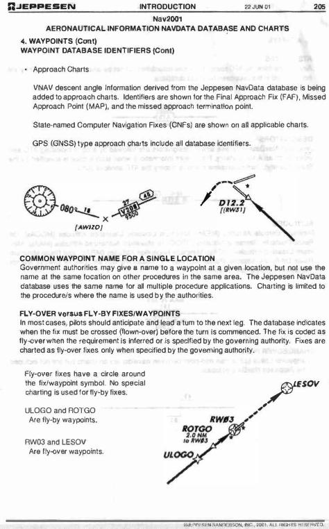
n.JEPPESEN INTRODUCTION 22JUN 01
Nav2001 AERONAUTICAL INFORMATION NAVDATA DATABASE AND CHARTS
4. WAYPOINTS (Cant) WAYPOINT DATABASE IDENTIFIERS (Cont)
Approach Charts
205
VNAV descent angle Information derived from the Jeppesen NayData database is being added to approach charts. Identillers are shown tor the Final Approach Fix (FAF), Missed Approach Point (MAP), and the missed approach termination point.
State-named Computer Nayigation Fixes (CNFs) are show!"! on aD applicable charts.
GPS (GNSS) type approach charts include aU database identifiers.
� J �080t....!!... X
� (AWIZO/
,-... � , .
I
COMMON WAYPOIHT NAME FOR A SINGLE LOCATION Goyernment authorities may give 8 !"I8me to a waypol!"!t at a give!"! location, but not use the name at the same location on other procedures In the same area. The Jeppesen Nay Data database uses the same name tor alt multiple procedure applications. Charting is limited to the procedureJs where the name Is used by the authorities.
FLY-OVER versus FLY-BY FIXESIWAYPOINTS In most cases, pilots should anticipate and lead a tum to the next leg. The database indicates when the li)[ must be crossed (liown-oyer) before the turn Is commenced. The fi)[ is coded as fly-over when the requirement Is Inferred or is speclfled by the governing authority. Fi)[es are charted as Ily-oyer fixes only when specified by the governing authority.
Fly-over lixes have a circle around the fi)[J'waypoint symbol. No special charting is used lor Ily-by lixes.
UlOGO and ROTGO Are fly-by waypoints.
RW03 and lESOV Are fly-oYSr waypolnts.
" ,
?fESOV ,-
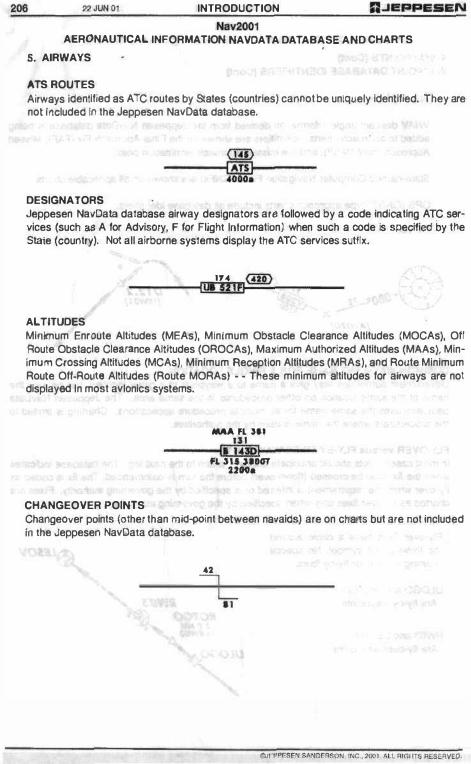
206 22 JUN 01 INTRODUCTION
Nav2001 AERONAUTICAL INFORMATION NAVOATA DATABASE AND CHARTS
5. AIRWAYS
"TS ROUTES Airways Identified as ATC routes by States (countries) cannot be uniquely identified. They are not Included 11'1 the Jeppesen NavDsls database.
DESIGNATORS
OID ------���------
Jeppesen NavData database airway designators are lollowed by a code Indicating ATC services (such as A for AdviSOry, F for Flight Information) when such a code is specified by the State (country). Not all airborne systems display the ATC services sutlhf.
ALTITUDES
I'" G!D I ... 511fl
Minimum Enroute Altitudes (MEAs), Minimum Obstacle Clearance Altitudes (MOCAs), Off Aoule Obstade Clearance Altitudes (OROCAsj. Mallimum Authorized Altitudes (MAAs), MinImum Crossing Altitudes (MCAs), Minimum Aect'lpllon Altitudes (MAAs), and Route Minimum Route Off·RoLlIS Altitudes (Roule MORAs) • • These minimum altitudes for airways are not displayed In most avIOnics systems.
CHANGEOVER POINTS
MAA FL JlI ---- '" '---li:illQl-No ,) .. ,IOOT
UoeI.
Changeover points (other than mld;Xlint between navaids) are on charts but are not Included in the Jeppesen NavData database.
" , L
"

:J.JEPPESEN INTRODUCTION 22 JUN 01
Nav2001 AERONAUTICAL INFORMATION NAVDATA DATABASE AND CHARTS
6. ARRIVALS AND DEPARTURES
PROCEDURES NOT IN THE DATABASE
207
Jeppesen publishes some officially designated departure procedures that include only text on IFA airport charts beneath the take-off minImums. They may be labeled 'Departure Proce· dure', 'IFA Departure Procedure", or "Obstacle DP'. Most 01 these are U.S. and Canadian procedures, although there Is a scattering 01 them throughout the world. Any waypoinVllx mentioned in the text Is in the Jeppesen NavData dataoase. However. these lexl-only depar· ture procedures ere not in the database.
T""E-QFF " OaSl.4.ClE DEI'AATURE I'ROCEDIJRf hy 1'1 1 .. , 35
,. VI ••• 1 .W , " 1 ... V, iT; NA ... V, oaSTACLE DP; Itwy 11, Climbing rlgitt tvrn ta �OOO· via heading 200' and m R·180 ta NaIwnt 020.0, befar. ptoc .. dlnl1 on cour .. 0.- AS OEARfO av ATC.
Some States publish narrative descriptions of their arrivals, and depict them on their enroute charts. They are unnamed, nol ldentilied as arrival routes, and are nOl lnclude(l in the Jeppe· sen NavData database. Some States publish 'DME or GPS Arrivals', and because they are otherwise unnamed, they are nOI included In the database.
PAOCEDURE TITLES Procedure Identifiers lor routes such as STARs, DPs and SIOs are In airtxlme databases but are limited to not more than sil( alpha/numeric characters. The database generally uses the charted computer code (shown enclosed within parentheses on the chart) lor the procedure title, as
CHART: DATABASE
Cyote Four Oeparture(CYOTE.CYOTE4) becomes CYOTE4.
When no computer code Is assigned, the name is truncated to not more than sil( characters. The database procedure Identifier is created according to the ARINC 424 speclficatiQns.
Database procedure identifiers are charted in most cases. They are the same as the assigned computer code (charted within parentheses) or are being added [enclosed within square brackets). Do not conruse the bracketed database Identifier with the official procedure name (which will be used by ATC) or the otlicial computer code (which Is used in flight plan rilIng).
4GO-FOOT CLIMBS Virtually all departures In the database Include a climb to 400 leet above the airport prior to turning because 01 requirements In State regulations and recommendations. The 400-loot climb Is not depicted on most charts. When States specify a height other than 400 feel, it will be in the Jeppesen NavData dataoase.
0JEt"PE8EN �RSON. INC .• 2OO . . .... l RlGHTS RESEIIVEa.

208 22 J lIN 01 INTRODUCTION A.JEPPI!SEN
Nav2001 AERONAUTICAL INFORMATION NAVDATA DATABASE AND CHARTS
6. ARRIVALS ANDllEPARTURES (Cont)
TAKE·OFF MINIMUMS AND CLIMB GRADIENTS The take-otl minimums and climb gradients that are depicted on the chaf'!9 /lie nOl lneluded In the database.
TN. SID r'qyl," a cliling and vi.ibllil� ot 1'100-3 IlnO a clImb gIlO\Wl\ 01 1\0'/1>11<0\ III 6000' . QIICI '�"O· I<II 75 ,eo 1500 200 250 300 4 1 0 ' p., N hI 513 &13 lOiS 1357 n08 2050
"EXPECT" and "CONDITIONAL" INSTRUCTtoNS Altitudes depicted on charts as ·E�pect· instructions, as "Expect to etDSS at 1 1 ,000'" are not included in the Jeppesen NavOsta database. When ·Conditlonal" statements such as "Straight ahead to ABC 8 DME 0( 600', whlche ... er is laler", are included on the charts, only one condition can be Included In the database.
ALTITUDES
D«II Ill. 11.7 WQI5 ,U iq>Kl 10 crl)l'
8, 1 1000'
Databases Include charted crossing altitudes at waypolntslflxes. Chart«l Minimum Enroute Altitudes (MEAs) and Minimum Obstacle Clearance Altitudes (MOCAs) are not included. The 5,()()()-loot altitude at AIANO Is included in the database. The MEAs between SURVE and the twO VORs are not Included.
STAR OVERLAPPING SEGMENTS STAAs normally terminate at a lix where the approach begins or at a Ilx where radar vectoring wUt begIn. When STAR termination points extend beyond the �lnnlng 01 the approach, some avionics equipment may display a route discontinuity at the end of the STAR and the first apPrOach nx.
A.JEPPEJiEN INTRODUCTION 22 JUN OI
Nav2001 AERONAUTICAL INFORMATION NAVDATA DATABASE AND CHARTS
7. APPROACH PROCEDURE (TITLES and OMITTED PROCEDURES)
209
ICAD PANS OPS approach procedure titles are officially labeled with the navald(s) uS&d tor the approach and are different than approach procedure t1Ues labeled according to the TEAPs criteria, which are labeled only with navalds required fO!' tha final approach segment. Because 01 the limited number 01 characters that are available IOf the procedure title, the name displayed 00 the avionics equipment may not be the same as the offICial name shown 0f1 the approach chart.
The Jeppesen NavOata database, In accordance with AAINC 424 specifications, codes Ihe approach procedure according (0 procedure type and runway number. 'Simifar'" Iype approaches to the same runway may be combined under one procedure litle, as ILS Rwy 1 6 and NOB VOA ILS Rwy t 6 may read as ILS Rwy 16. The actual avionics readout for the procedure litle varies from manufacturer to manufacturer.
Some avionics systems cannot display VOA and VOA DME (or NOB and NOB OME) approaches to the same runway, and the approach dIsplayed will usualty be Ihe one aSS()Ciated wilh OME.
Currentl}l: Generally. most Cat I, II, and III ILS approaches 10 the same runway are the same basic procedure, and the Cal l procedure is In the database. However, In Isolated cases, the Cat I and Cal 111111 missed approach procedures are different, and only the Cal l missed approach will be in the database.
Additionally, there may be ILS and Converging tLS approaches to the same runway. While the converging ILS approaches are not currently In the database, they may be at some later date.
Some Stales are usmg the phonetic alphabet to indicate more man one 'same type, same runway' approach, such as ILS Z Awy 23 and IlS Y Awy 23. The phonetic alphabet starts are the end of the alphabet to ensure there is flO possIbility of conniel with circling only approaches, such as VOR A.
In isolated cases, proceduras are intentionally omitted from the database. This occurs primarily when navaidlWaypoint coordinates provided by the authorities in an undeveloped area are Inaccurate. and no resolution can be obtained. Additionally, the AAINC 424 specifications governing navigation databases may occasionally prohibit the Inclusion of an approach procedure.
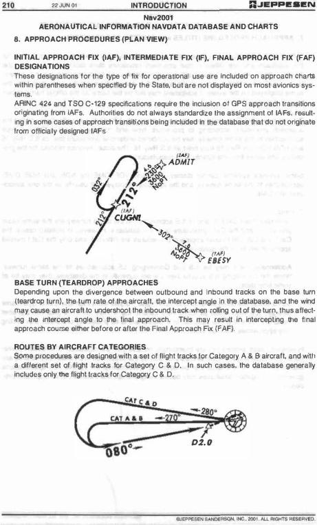
210 22 JUN 0 1 INTRODUCTION RJepPI!.I!N
Nav2001 AERONAUTICAl lNFORMATtON NAVOATA DATABASE AND CHARTS
8. APPROACH PROCEDURES (PLAN VieW)
INITIAL APPROACH FIX (IAF), INTERMEDIATE FIX (IF). FINAL APPROACH FIX (FAF) DESIGNATIONS These designations lot the type of fix 101' operallOnal use are Included on approaCh Charts within parentheses when specffled by the Stale, but are not displayed on most avionics systems. ARINC 424 and 150 C-129 specifications require the inclusion 01 GPS approach transitions originating from IAFs. Authorities do not always standardize the assignment 01 IAFs, resulting In some cases of approach transitions being Included In the database that do not Originate from officially designed IAFs
""'! CUGN!" JO<,�,
(I"'�) lYO..or EBESY
BASE TURN (TEARDROP) APPROACHES Depending upon the divergence between outbound and Inbound tracks on the base turn (teardrop turn), the tum rate 01 the aircraft, Ule Intercept angle In the database, and the wind may cause an aircraft to undershoot the Inbound track when rolling oot of the turn, thus affecting Ine intercept angle to the final approach. This may result in intercepting Ine final approach course either before or atter the Final Approach FIX (FAF).
ROUTES BY AIRCRAFT CATEGORIES Some procedures ere designed with a sel 01 flight tracks lor Category A & B aircraft, and with a different set of flight tracks for Category C & D. In such cases, the database generally includes only the flight tracks for Category C & D.
CAT A & . -
--"0--800- oz. 0
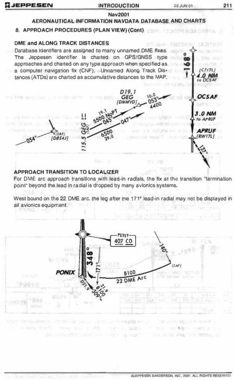
:;.JEPPESEN INTRODUCTION 22.RJNOI
Nav2001 AERONAUTICAL INFORMATION NAVDATA DATABASE AND CHARTS
8. APPROACH PROCEDURES (PLAN VIEW) (Cont)
OME and ALONG TRACK DISTANCES
Database IOentiflers are assigned to many unnamed DME IbeBs. The Jeppesen identifier is charted on GPSlGNSS type approaches and charted on any type approach when specified as a computer navigation lix (CNF). Unnamed Along Track Dis· tances (ATDs) are charted as accumtJlative distances to the MAP.
APPROACH TRANSITION TO LOCALIZER
0 .. ... -t [CFf7Lj
�.O NNI 'co OCSAF
OCSAF
J.O NNI 'co Af'Rf}f'
APRUF [RW/7!]
, {" , � , . \
211
For DME arc approach transitions with lead-in radials. the Ilx al the transition 'termination point" beyond the lead In radial is dropped by many avloolcs systems.
West bound on the 22 DME arc. the leg after the 171" lead-in radial may nOI be displayed In ail avionics equipment.
�.r'--_1. PETEY 407 CO
(1""/
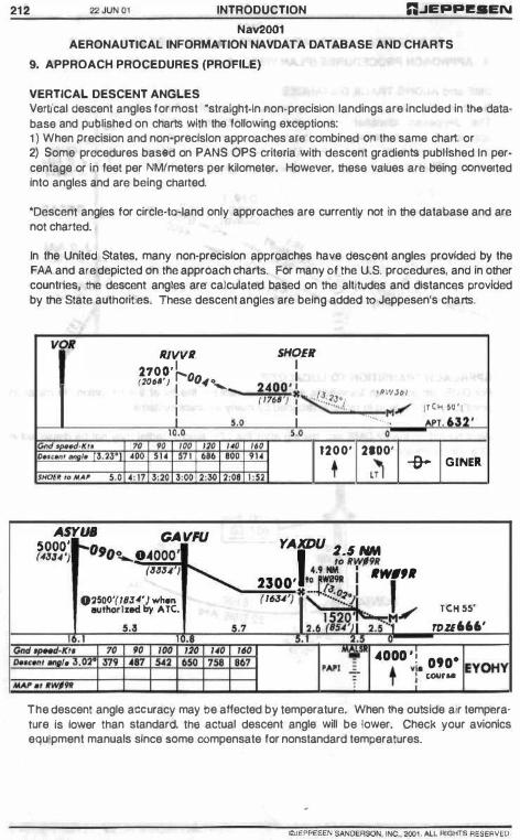
22 JVN II I INTRODUCTION G.J�ppe.EN
Nav2001 AERONAUTICAL INFORMATION NAVDATA DATABASE AND CHARTS
9. APPROACH PROCEDURES (PROFilE)
VERTICAL DESCENT ANGLES Vertical descent angles lor most ·stralghl·ln non· precision landings are Included in the data· base and publish&d on charts with the following exceptions: 1) When precision and non·preclslon approaches ate combined on the same chart or 2) Some procedures bas&d on PANS OPS criteria with descent gradients published In per· centage or in feet per NMimeters per kilometer. However, these values afe being converted Into angles and are being charted.
'Descenl angles tor circle·ta-Iand only approaches are currently nol ln the database and are not charted.
In the United States, many non·precislon approaches have descent angles provided by the FAA and afe depicted on the approach charts. For many 01 the U.S. procedures, and In other countries, the descent angles are calculated based on the altitudes and distances provided by the State authorities. These descent angles are being added to Jeppesen's charts.
yo.t IlIVVIl
2700, 1 (Xl"') r--OO,,\o...
1 � 1 1
10.0
"" · K " " " ,� '" _ .. ", • • •
JHOI' .. "A� . , ' : 11 3:20 3:00 2:3(1
ASYlJI! 5000' r-( GA VFU (4JUj O'O�O4000'
("J"4 )
02S00'(J1J4') wt..n •• ,nhorlled &, ATe.
••• " " '" '" '"
'"
1:08
M '"
SHOEIl 1 1
a�9r ' " 6d I �"' • .:�U::':t '"
1 ..
.. , 1200'
'�WJ¢I ,- 1'('" �', ... � ... !:' . . '" ,
2.00' • t ,71 -&- GINER
1 : 52
YAXDU �.S "" , toftWl"
2300' � I 1tW#,. ( 16J4'! 3� ' TCH 55' 1529 . M/
2.6 ,,u"l)1 'u ::: f{ rou666' �K" o..c ... , I • . ." .., '" '" ". �. ." .�, , 4000 ' ! 090-�YOHY t ", lUI,. . , .WlN ' cou, ..
The descent angle aCClJracy may be affected by temperature. When Ih8 outside air tempera· lure Is lower than standard, tha actual descent angle will be lower. Check your avionics equipment manuals since 80me compensate lOf nonstandard temperatures.
OJEPPESEI< SN<OE'ISON , INC.. 200 1. AU. R U,lH1'S RESERVED .
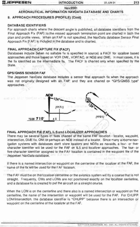
RJEPPESEN INTRODUCTION 22JUNOl
Nav2001 AERONAUTICAL INFORMATION NAVDATA DATABASE ANO CHARTS
g. APPROACH PROCEDURES (PROFIL.E) (Cont)
DATABASE IDENTIFIERS For approach charts where the descent angle Is published, all database identifiers from the Final Approach Fix (FAF) to the missed approach termination point are charted in both the plan and prolile views. When an FAF Is not specilled, the NavData database Sensor Final Approach Flit (FAFl ls Included In the database and Is chart&d.
FINAL. APPROACH CAPTURE FIX (FACF) Databases Include (when no suitable tlx is specified In source) a FACf tor localizer based approaches and those based on VOR OME, VORTAC. or NOB and OME. In most cases, it Is the fix Identified as the intermediate fix. The FACF Is charted Ollly when specHled by the State.
GPSlGNSS SENSOR FAF The Jeppesen NavData database Includes a sensor tinal approach fix when the approach was not originally designed with an FAF, and they are charted on "GPSlGNSS type" approaches.
NOB r-124° ___ {FFJIJ
TOZE 1 . O' 4.0
FINAL. APPROACH FIX (FAF), ILS and LOCAL.lZER APPROACHES There may be several types 01 fixes charted at the same FAF location - locator, waypolnt, intersection, DIv1E lix, OM, or perhaps an NOB Instead of a locator. Since many airborne nav· Igation systems with databases don't store locators and NOBs as navalds, a lour- or fivecharacter Identifier will be used lor the FAF on ILS and localizer approaches. The four- or five-character Identifier assigned to the FAF location is contained in the waypoint OJe 01 the Jeppesen NavOata database.
II there is a named intersection or waypoint on the centerline of the localizer at the FAF, the name ol lhe lix will be used tor the FAF loca tion.
The FAF must be on the localizer centerline or the avionics system will fly a course that is not straight. Frequently, OMs and lOMs are not positioned exactly on the localizer centerline, and a database lix is created to put the aircraft on a streight course.
When the LOM is on the centerline and there also Is a named Intersection or waypolnt on the centerline, the name of the Intersect ion or waypolnt will be used for the FAF. For CHUPP LOMllntersection, the database Identifier is ·CHUPP� beCause there Is an Intersection or waypolnt on the centerline 01 the localizer at the FAF.
�PPES Hi SAIIOiO/lSON. 1 N C . ,001 �L1."'G/"s ,...�n w r. o
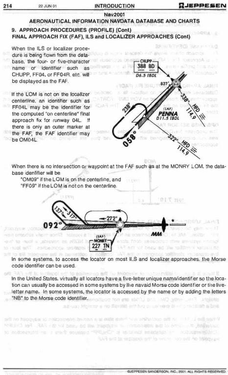
214 22 JUN 01 INTRODUCTION n.JI!'PPE5EN
Nav2001 AERONAUTICAL INFORMATION NAVDATA DATABASE AND CHARTS
9. APPROACH PROCEDURES (PROfiLE) (Cont) FINAL APPROACH FIX (FAF), ILS and LOCALIZER APPROACHES (Coni)
When the ILS or localizer proce· dure Is beIng IIown from the data· base. the four- or IIve-characler name or identifier such as CHUPP, FF04, or FF04A, elc. will be displayed as the FAF.
II the LOM Is not on the localizer centenine, an Identifier such as FF04L may be the Identifier lor the computed "OIl center1ine" final approach fix for runway 04l. If there Is only an ouler marker al the FAF, the FAF identifier may be OMQ4L.
When there Is no Intersectlon or waypolnt at the FAF such as al the MONAY LQM, the database ldenUfler will be
'OM09' if the LDM Is on the centerline, and "FF09' II the LOM is not on the centerline.
In some systems, to access the locator on most ILS and localizer approaches, tile Morse
code Identifier can be used.
In the United States, virtually all locators have a five-letter unique name{ldentifier so lIle location can usually be accessed In some systems by lIle navaid Morse code identifier or lIle liveletter name, In some systems, lila locator is accessed by the name or by adding the letters °NB' to !he Morse code Identifier.

RJEPPESEN INTRODUCTION 22JUNOI
Nav2001 AERONAUTICAL INFORMATION NAVDATA DATABASE AND CHARTS
9. APPROACH PROCEDURES (PROFILE) (Cont)
215
NAMED and UN·NAMED STEPDDWN FIXES, FINAL APPROACH FIX (FAF) to MISSED APPROACH POINT (MAP) Named and un·named stepdown fixes between the F,6.F and MAP are currently not Included In the databases, but will be added In the future. They are allen OME fixes. and in those cases, can be identified by OME. The distance 10 go to the MAP may be labeled on some GPSlGNSS type charts and VOR DME RNAV charts. Proper identification of these displayed fixes is necessary to clear all stepdoWn fix crossing altitudes.
DA(H) In _OM
MDA{H). 2.' "" JUZAN
RWJ' fg flW;J1 ,;", .... 1
ILS AND RUNWAY ALIGNMENT
5500' AVAIH.
Differences in government specified values for localizer and airport variation may cause apparent non·alignment of the kx:alizer and the runway. These differences are gradually being resolved, and whell8ver possible the airport variation is used for the localizer variation.
10. APPROACH PROCEDURES (MISSED APPROACH)
MISSED APPROACH POINT (MAP) For non'precision approaches, when the MAP Is other than a naveid, there will be a database MAP waypoint with a unique identifier. If the MAP is a waypoint and is at or within 0.14 NM of the threshold the MAP identifier will be the runway number, as "RW04" fOl'" Awy 4 threshold. If the MAP is not at the runway, there witl either be an official name lor the MAP, or an identifier is provided. GPSlGNSS type approaches, and charts with descent angles, include the data· base identifier of the MAP.
... ...... � ,-l
DIJ� I fWU} \.
__ SEN SAI«lERSON . INC. , 200 " IoU- RIGHTS f<ESERV£D .
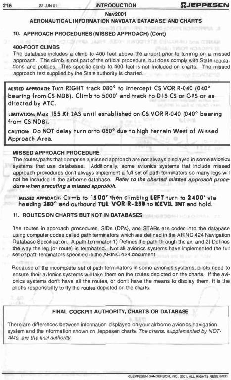
216 22JUN Ol INTRODUCTION n.JEPPI!IiEN
Nav2001 AERONAunCAliNFORMAT10N NAVDATA DATABASE AND CHARTS
10. APPROACH PROCEDURES (MISSED APPROACH) (Cont)
400-FOOT CLIMBS The database Includes a climb to 400 leet above the airport prior to turning on a missed approach. This climb Is no1 part 01 the official procedure, but does comply with Stale regulations and policies. This specific climb to 400 leet Is not included on charts. The missed approach text supplied by the State authority Is charted.
MlSSlD AI'I'ftOACH, Turn RIGHT track 0800 to intercept CS VOR R·040 (040" bearing 'rom CS NOB). Climb to 5000' and track to D 1 5 CS or GPS or 8S directed by ATC.
UMITATIOH: Max 185 Kt lAS until establ ished on CS VOR R·040 (040" bearing from CS NOB).
CAUTION, Do NOT delay turn onto 080" due to high terrain West of Missed Approach Area.
MISSED APPROACH PROCEDURE The routes/paths that comprise a. missed approach are not always displayed in some avionics systems that use databases. Additionally, some avionics systems that Include missed approach procedures don't always Implement a full set of path terminators so many tegs wilt not be Included In the airborne database, Refer to thfJ charted ml.-ed approach procedure when executing a ml ... d tlpprCHICh.
MI'SID -"'"OACH, Climb to 1500' then climbing UfT turn to 2400' .... ia needing 210· and outbound rul VOR R-231 to KEVIL INT and hold,
11. ROUTES ON CHARTS BUT NOT IN DATABASES
The routes In approach procedures, SIOs (OPs), and STARs are coded into the database using computer codes called path terminators which are delined in the ARINC 424 Navigation Database Specification. A path terminator 1 ) Defines the path through the air, and 2) Defines the way the leg (or route) is terminated. Not all avionics systems have Implemented the full set 01 path terminators specified in the ARINC 424 document.
Because 01 the incomplete set of path terminators in some avionics systems, pilots need to ensure their avionics systems will take them on the routes depicted on the charts. li the avionics systems don1 have all the routes, or don' have the means to display them, it is the pllofs responsibility to fly the routes depicted on the charts.
FINAL COCKPIT AUTHORITY, CHARTS OR DATABASE
There are differences between Information displayed on your airborne avionics navigation system and the Information shown on Jeppesen charts. The charTS, supplemented by NOTAMs, are the final authority.

A.JEPPESEN INTRODUCTION 22 JUNO l 217
Nav2001 AERONAUTICAL INFORMATION NAVDATA DATABASE AND CHARTS
GLOSSARY/ABBREVIATIONS
AIRAC • Aeronautical InlormatiOn Regulation and ContrOl. Designates the revision cycle apecilled by ICAO, normally 28 days.
ARINC • Aeronautical Radio, Inc
ATD · Along Track Distance. as "3 NM to RW24".
ATS Route· Officially designated route. No designator assigned.
CNF • Computer NavigatiOn Fix
DATABASE IDENTIFIER · Avionics system use only. not lor flight plans or ATC communications. Identifies a waypoint or lix.
DP - Departl..lre Procedure
FAA· Federal Aviation Administration
FACF - Final Approach Capture Fix. Database includes (usually as an intermedlata fix) when no suitable fix Is specilied in source.
FAF • Final Approach Fix
FLY·BY FIX · Waypolnl allows use 01 tum anticipation to avoid overshoOt 01 the nexllllght segment.
FLY-OVER FIX · Waypoint precludes any tum unlil the fix is over Mown and is fOllowed by an Intercept maneuver 01 the next flight segment.
FMS • Flight Management System
GNSS · Global Navigation Satellite System
GPS - Global Positioning System
GPSlGNSS SENSOR FAF - Database fix that changes sensitivity of the Course Deviation Indicator (COl) on linal approach.
GPSlGNSS TYPE APPROACHES · Any approach that can be llown with GPSlGNSS as the only source 01 navigation.
ICAO· International Civil Aviation Organization
IAF · Initial Approach Fix
IF • Intermediate Approach Fix
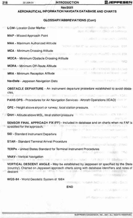
21B Z2 JVN OI INTRODUCTION
Nav2001 AERONAUTICAL INFORMATION HAVDATA DATABASE AND CHARTS
GLOSSARY/ABBREVIATIONS (Cont)
LOM· Locator Outer MClrkor
MAP · Missed Approach Point
M.A.A • Maximum Authorized Altitude
MeA - Minimum Crossing Altitude
MOCA - Minimum Obstacle Crossing Altitude
MORA - Minimum Off-Route Altitude
MRA - Minimum Reception Altitude
NavData • Jeppesen Navigation Data
OBSTACLE DEPARTURE - An instrument departure procedure BstabHshed to avoid obstacles.
PANS OPS - Procedures lor Air Navigation Services - Alrcralt Operations (ICAO)
OFE - Height above airport or runway, local station pressure.
QNH - Altitude above MSL. lOCal station pressure
SENSOR FINAL APPROACH FIX (FF) - Included In database and on charts when no FAF Is
specified for the approach.
SID - Standard Instrument Departure
STAR - Standard Terminal Arrival Procedure
TERPs • United States Standard for Terminal Instrument Procedures
VNAV · Vertical Navigation
VERTICAL DESCENT ANGLE · May be established by Jeppesen or specified by the State (country). Charted on Jeppesen approach charts along with database identifiers and rates 01 descent
WGS·84 · World Geodetlc System 01 1984
END


