
Japanese Advanced Meteorological Imager (JAMI): Design, Characterization and Expected On-Orbit Performance
Jeffery J. Puschell*, Howard A. Lowe, James Jeter, Steven Kus, Roderic Osgood,
W. Todd Hurt, David Gilman, David Rogers, Roger Hoelter Raytheon Space and Airborne Systems, Santa Barbara Remote Sensing
Ahmed Kamel Space Systems/Loral
ABSTRACT
The Japanese Advanced Meteorological Imager (JAMI) was developed by Raytheon and delivered to Space Systems/Loral as the Imager Subsystem for the Japanese MTSAT-1R system. Detailed characterization tests show JAMI meets all MTSAT-1R requirements with margin. JAMI introduces the next generation of operational weather imagers in geosynchronous Earth orbit (GEO) and provides much improved spatial sampling, radiometric sensitivity, Earth coverage and 24-hour observation capability compared with current GEO imagers.
Keywords: remote sensing, advanced technology, meteorological imaging, geosynchronous orbit
* Correspondence: Jeffery J. Puschell, Raytheon Space and Airborne Systems, Santa Barbara Remote Sensing, 75 Coromar Drive, B32/15, Goleta, CA 93117 USA; e-mail: [email protected].
Figure 1. JAMI is prepared for thermal-vacuum and calibration testing, in advance of its delivery on 2003 June 17.

1. INTRODUCTION
Raytheon Santa Barbara Remote Sensing built the Japanese Advanced Meteorological Imager (JAMI) for Space Systems/Loral as the Imager Subsystem for Japan’s MTSAT-1R multifunctional satellite system. MTSAT fulfills a meteorological mission by providing timely, high quality full-disk multispectral imagery for operational weather needs in Japan, East Asia and Australia along with a civil aviation mission by relaying digitized voice data and other data for aircraft along with radio navigation signals. MTSAT-1R is a replacement satellite for MTSAT-1, which was destroyed at launch on 1999 November 15. Due to Japan’s urgent need to replace MTSAT-1, JAMI was developed on a challenging schedule that began with the Japanese request for proposal on 2000 January 11 and resulted in instrument delivery on 2003 June 17, roughly three and half years later. Raytheon’s success in responding to the needs of MTSAT-1R and delivering an excellent operational GEO imager was enabled by an elegant instrument architecture and use of newer but proven technology that simplified design, assembly and test of the Imager while simultaneously supplying superior performance. A dedicated and talented management and test team (cf. Figure 1) characterized performance of this innovative, advanced technology design with unmatched efficiency. As shown below, JAMI breaks through limitations of earlier three-axis stabilized GEO instruments with significant improvements in many areas, including spatial sampling, radiometric sensitivity, calibration and performance around local midnight.
2. DESIGN
Puschell et al.1 described many of the design characteristics of JAMI. Figure 2 illustrates an isometric view of the imager. Table 1 compares general design and measured performance characteristics of JAMI with MTSAT-1R requirements.
Figure 2. JAMI provides data with unprecedented detail and fidelity by means of recently proven new technology such as active cooling that was implemented successfully in a compact, efficient design architecture.
ACE
DEWAR
ACTIVE COOLER
TELESCOPE
SCANMIRROR
ACE
DEWAR
ACTIVE COOLER
TELESCOPE
SCANMIRROR
Design features. JAMI covers the 0.55 µm to 12.5 µm spectral region using the required 4 infrared bands and 1 visible wavelength band that are listed in Table 1. JAMI’s thermal IR bands have fully redundant 84 element 1-d arrays that sample Earth with 2 km ground-projected instantaneous field of view (IFOV) at nadir. The visible band has 336 element 1-d arrays that sample Earth with 0.5 km ground-projected IFOV at nadir. These large format arrays enable faster full disk coverage rate with slower scan rate than current systems. Benefits of slower scan rate include better radiometric sensitivity, a longer life scanner and less impact on the spacecraft. JAMI covers the full Earth disk, including all required pointing verification and calibration scans, in ~24 minutes. An onboard calibration system for all bands is built into the imager. The imager provides a 21.4 deg (N-S) by 23.6 deg (E-W) full frame scan area that is centered at the projection of spacecraft nadir on Earth (Figure 3). After launch in 2004, JAMI will be stationed at the 140 E longitude orbital slot that has traditionally been reserved for operational weather imaging for Japan, East Asia and Australia. JAMI’s full frame includes a complete view of Earth as well as views of cold space for calibration and star sensing. Raytheon’s JAMI design is based on advanced imager technologies that have already been space-qualified and flown in research systems such as MODIS and MTI. The design addresses and mitigates limitations of existing operational GEO imagers with respect to performance around local midnight, spatial sampling, radiometric sensitivity, calibration and image navigation and registration. The heart of the design is a wide field-of-view, off axis telescope that enables an elegant two focal plane architecture while intrinsically mitigating effects of sunlight shining directly into the instrument aperture around local midnight, the single most challenging design issue for a GEO imager. The two focal plane design offers significant advantages with respect to other design approaches. These include separation of visible and infrared arrays to improve cooling performance of the infrared arrays, better throughput and a much simpler and easier to build optical layout than previous operational imagers. The off axis telescope offers better MTF performance and reacts less to solar heating than current system designs because no central secondary mirror with support spider is present to be heated by the Sun and distort optical performance, as in current operational imagers. This advanced MTSAT imager represents the best balance between heritage and newer space-qualified technology. Use of proven second-generation focal plane technology from MODIS, MTI and other Raytheon programs improves radiometric and calibration performance eliminates 1/f noise striping problems of current operational imagers while simplifying instrument integration and test. JAMI’s active cooler enables exceptional radiometric sensitivity performance over a long life using an approach flight
Parameter MTSAT-1R Requirement JAMI PerformanceSpectral Channels Visible: 0.55 µm to 0.75 - 0.90 µm
IR1: 10.3 µm to 11.3 µm IR2: 11.5 µm to 12.5 µm
IR3: 6.5 µm to 7.0 µm IR4: 3.5 - 3.8 µm to 4.0 µm
Visible: 0.55 µm to 0.90 µm IR1: 10.3 µm to 11.3 µm IR2: 11.5 µm to 12.5 µm
IR3: 6.5 µm to 7.0 µm IR4: 3.5 µm to 4.0 µm
Detector Sample Resolution at Nadir Design Dependent 0.5 km (visible), 2 km (infrared)HiRID Data Ground Resolution 1.25 km (visible), 5.0 km (infrared) 1.0 km (visible), 4.0 km (infrared)HRIT Data Ground Resolution 1.0 km (visible), 4.0 km (infrared) 1.0 (visible), 4.0 km (infrared)MTF(IR2) at 4473 rad-1(Observation Data) >0.25 >0.44Field of View Design Dependent 0.269 deg per swath
Image Frame 17.6 deg (N-S) by 17.6 deg (E-W) 21.4 deg (N-S) by 23.6 deg (E-W)Detector Array Lengths Design Dependent 336 (visible), 84 (infrared)Detector Operating Temperatures Design Dependent Ambient (visible), 75 K (IR)Full Disk Coverage Time <30 min <24 minCalibration Accuracy (One Observation) Analysis in progress on 2003 August 1
2.5% (visible) 0.21 K (IR at 300 K) 0.10 (IR at 220 K)
2.5% (visible) 0.08 - 0.16 K (IR at 300 K) 0.08 - 0.10 K (IR at 220 K)
Table 1. JAMI’s measured performance meets MTSAT-1R requirements with significant margin.

10.7 deg
10.7 deg
11.8 deg 11.8 deg
Full Frame Scan Area
12.5 deg
Vis Cal
Nadir
Figure 3. JAMI's full frame scan area accommodates full disk imaging, calibration and star sensing and exceeds MTSAT-1R requirements.

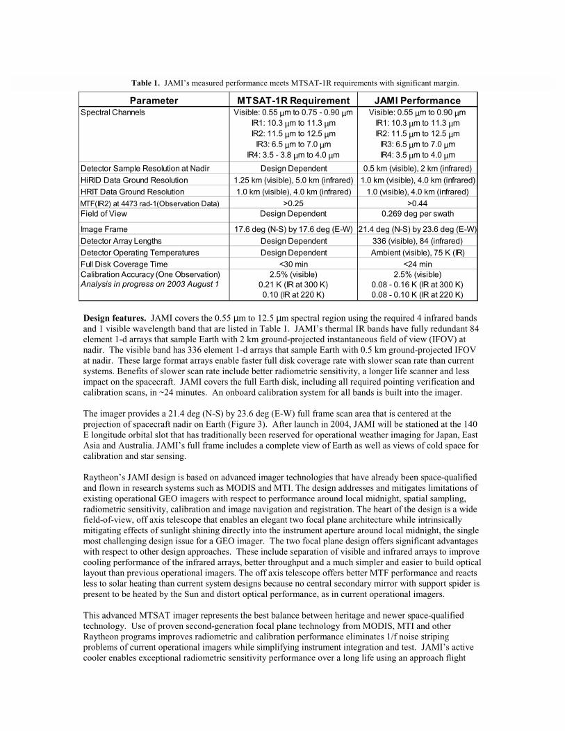
tested most recently in MTI and AIRS. The combination of focal plane technology, optical configuration and scan approach designed into JAMI provides spatial resolution, MTF and radiometric sensitivity performance that is superior to current operational GEO imagers, while also eliminating the “keep-out zones” and instrument down times caused by solar intrusion effects on current systems. Built-in modularity simplified imager system integration and facilitated selection and insertion of alternative subassemblies or component elements as dictated by cost, performance and schedule issues. JAMI embodies first use of all PV detector arrays for the infrared bands in an operational meteorological instrument, first use of second-generation focal plane technology in an operational meteorological instrument, first use of active cryogenic cooling of infrared focal plane arrays in an operational meteorological instrument and in GEO and first deliberate use of Nyquist sampling of pixels in an operational meteorological instrument. Design description. A gimbaled two-axis scan mirror relays input scene radiance to an off axis focal telescope. The scanner can be commanded to point outside this full frame scan area and provide views of onboard blackbody and albedo monitoring sources. The scan function for this imager is completely flexible. For example, regions of any size within the imager frame may be scanned. Scan mirror pointing can be adjusted during each scan by commands from the spacecraft that correct for pointing errors resulting from spacecraft attitude variations. Full disk coverage time for this imager, including all pointing verification and calibration source observations, is about 24 minutes. Half disk coverage time including verification and calibration measurements is about 13 minutes. A focal three-mirror off axis reflective telescope (cf. Figure 4) collects and focuses input radiance onto two focal planes which spatially sample Earth at the Nyquist rate for pixels with 4 km IR ground resolution and 1 km visible ground resolution. The re-imaged focal three-mirror anastigmat (TMA) telescope delivers diffraction-limited performance over a wide flat field, with superior stray light rejection to improve performance in all spectral bands, especially in the visible and IR4 (3.75-µm) bands. JAMI’s Nyquist spatial sampling improves radiometric accuracy of resampled and registered data compared with current operational systems that undersample the Earth scene. Furthermore, its higher spatial sampling rate enables improved image navigation and registration by providing better daytime and nighttime landmarking and better capability to determine non-static visible-infrared co-registration errors by viewing landmarks at high resolution. Detector arrays in both focal planes are completely redundant and contain monolithic detector arrays that use materials optimized to their spectral regions. As shown in Figure 5, two columns of detectors are fabricated for each infrared band. This provides a primary and an alternative detector element, individually selectable during focal plane subsystem integration and testing and even during flight operations in GEO to improve producibility of 100% operable arrays and provide an additional degree of redundancy to support long-life operation. Characterization testing showed that all of JAMI’s arrays are 100% operable, without making use of alternative detector selections. This second-generation Raytheon technology provides excellent sensitivity, low noise, very low power and simple electrical and mechanical interfaces. Each focal plane contains one set of arrays for each spectral band in that plane with individualized spectral filters over the arrays. The visible array is uncooled and uses technology already proven in a number of Raytheon programs, including EO-1. The infrared bands are contained in two sensor chip assemblies (SCAs), a design approach already proven on TRMM/VIRS, MODIS and MTI. The infrared focal plane operates at a temperature of 75 K. The manufacturing alignment tolerances of these arrays built with semiconductor device lithographic techniques provide deviations in relative detector sample locations that are far superior to misalignments associated with manual assembly processes. The combination of this advanced focal plane technology with the Nyquist sampling approach used by JAMI and the resampling of detector samples on the ground to create pixels enables unsurpassed band-to-band pixel registration. Signal processing electronics convert the Nyquist-sampled focal plane output to digital form, process and format the raw data for transmission to the JAMI Ground Processor. JAMI delivers 12-bit dynamic range data, which enables low light level visible band measurements that improve image navigation performance

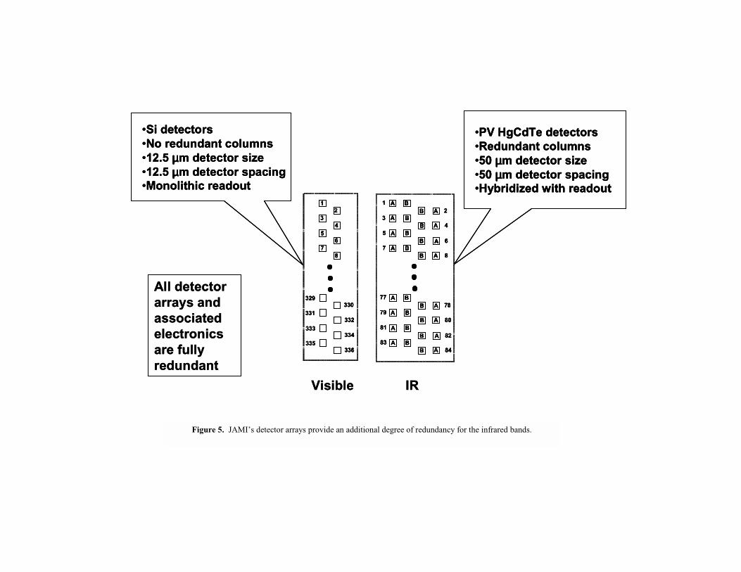
at night and provide forecasters with better data to discern fog and severe weather outflow boundaries earlier in the morning as well as later at night. JAMI transmits 2-km infrared data in normal operating modes and can provide 0.5-km visible band data on demand. Higher spatial resolution data improves cloud edge detection and tracking, which results in more accurate wind drift information, better capability to describe and forecast behavior of rapidly evolving weather systems and better typhoon tracking. Furthermore, JAMI will enable identification of smaller scale phenomena such as fog, cloud-top thermal gradients and outflow boundaries that are unresolved by current systems. The JAMI Ground Processor transforms JAMI data from its Tapered Elevation Scan (Figures 6 and 7) native format into a GOES-like fixed grid in scan angle space, calibrates and then transmits that data to the MTSAT Image Data Acquisition and Control System (IDACS). The better spatial sampling provided by JAMI improves data quality compared with existing systems. Calibration is provided through several mechanisms that are designed to work together to supply accurate, stable performance: space view and V-groove blackbody source (already flight-proven on TRMM/VIRS and MODIS) for the infrared bands and a reflective solar albedo monitor for the visible band. The albedo monitor design is derived from heritage approaches developed over decades of onboard visible wavelength calibration work with Landsat, TRMM/VIRS, SeaWiFS and MODIS.
3. CHARACTERIZATION
JAMI performance was characterized during a comprehensive series of subsystem and system-level tests. JAMI entered the thermal-vacuum chamber twice. The first test series was a 31-day run that was stopped just a few hours before planned completion by an electrical short in the redundant winding of the north-south scan motor. The final test series was a 17-day run that occurred shortly before instrument delivery. All aspects of required JAMI performance were tested and verified. For instance, measured Line of Sight (LOS) stability was measured to be 3-µrad versus the 6-µrad requirement. This higher level of performance enables much improved Image Navigation and Registration (INR) with respect to previous systems. LOS stability was not affected by the active cooler. This paper summarizes results from a few of the more important tests and associated analyses including:
1. End-to-end performance verification 2. Radiometric sensitivity (signal-to-noise ratio and NEDT) 3. Spectral response 4. Line spread function and MTF 5. Performance around local midnight.
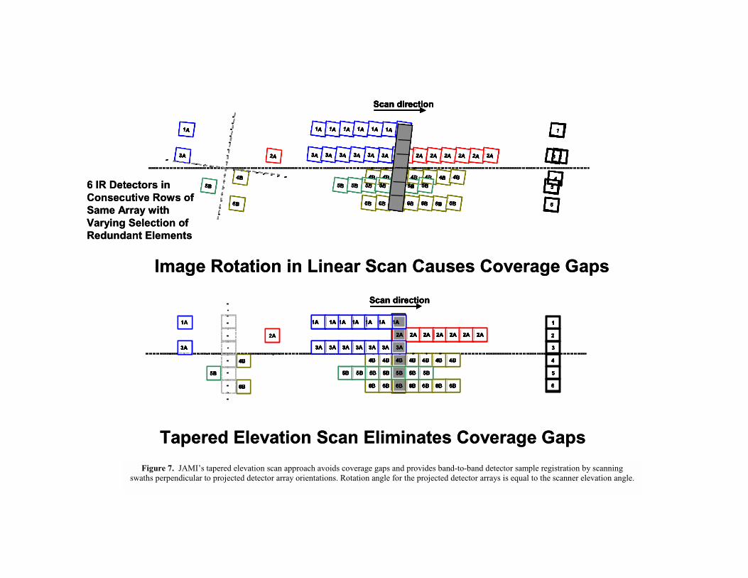
End-to-end performance verification. One of the earliest system-level tests verified JAMI’s end-to-end function and Earth coverage performance. Frames of JAMI data like that shown in Figure 8 were collected by scanning the instrument in full disk observation mode across a projected GOES-12 image. The projector, which was originally part of an airborne reconnaissance system, functioned as a very large format, wide field of view collimator for this application. The physical extent of the projected Earth image corresponds to the view from GEO. The end-to-end tests showed that JAMI meets requirements in a number of important performance areas including full disk coverage time, line-of-sight repeatability, pixel-to-pixel simultaneity and data latency. Radiometric sensitivity. JAMI’s radiometric sensitivity was measured in all spectral bands with both primary and secondary detector arrays. As shown in Table 2, measured JAMI performance meets sensitivity requirements with comfortable margin in all bands. Margin ranges from roughly a factor of three in the 12.0-µm band (IR2) up to about a factor of eight in the visible, IR1 and IR4 bands. Figure 9 shows that detector response to a uniform scene in the visible is very consistent across both arrays, especially for the primary (or A) array. SNR for one detector on the B side fell far below the others

DICHROIC BEAMSPLITTERREFLECTS VIS BAND AND TRANSMITS IRVIS FPA
IR FPA
PRIMARYMIRROR
SECONDARYMIRROR
TERTIARYMIRROR
2 AXIS SCAN MIRROR
DICHROIC BEAMSPLITTERREFLECTS VIS BAND AND TRANSMITS IRVIS FPA
IR FPA
PRIMARYMIRROR
SECONDARYMIRROR
TERTIARYMIRROR
2 AXIS SCAN MIRROR
DICHROIC BEAMSPLITTERREFLECTS VIS BAND AND TRANSMITS IRVIS FPA
IR FPA
PRIMARYMIRROR
SECONDARYMIRROR
TERTIARYMIRROR
2 AXIS SCAN MIRROR
Figure 4. JAMI’s straightforward optical layout is at the heart of this advanced technology instrument.
12
3
5
7
4
6
8
A BAB
ABA B
A B
AB
BA
A
B
78
80
82
84
A BAB
ABA B
A B
AB
BA
A
B
77
79
81
83
12
34
56
78
329330
331332
333334
335336
Visible IR
•Si detectors•No redundant columns•12.5 µµµµm detector size•12.5 µµµµm detector spacing•Monolithic readout
•PV HgCdTe detectors•Redundant columns•50 µµµµm detector size•50 µµµµm detector spacing•Hybridized with readout
All detector arrays and associated electronics are fully redundant
12
3
5
7
4
6
8
A BAB
ABA B
A B
AB
BA
A
B
78
80
82
84
A BAB
ABA B
A B
AB
BA
A
B
77
79
81
83
12
3
5
7
4
6
8
A BAB
ABA B
A B
AB
BA
A
B
78
80
82
84
A BAB
ABA B
A B
AB
BA
A
B
77
79
81
83
12
34
56
78
329330
331332
333334
335336
12
34
56
78
329330
331332
333334
335336
Visible IR
•Si detectors•No redundant columns•12.5 µµµµm detector size•12.5 µµµµm detector spacing•Monolithic readout
•Si detectors•No redundant columns•12.5 µµµµm detector size•12.5 µµµµm detector spacing•Monolithic readout
•PV HgCdTe detectors•Redundant columns•50 µµµµm detector size•50 µµµµm detector spacing•Hybridized with readout
•PV HgCdTe detectors•Redundant columns•50 µµµµm detector size•50 µµµµm detector spacing•Hybridized with readout
All detector arrays and associated electronics are fully redundant
Figure 5. JAMI’s detector arrays provide an additional degree of redundancy for the infrared bands.

Figure 6. JAMI scans the Earth with swaths whose elevation angle changes with East-West location.
1A
3A
5B
4B
6B
2A
1A
3A
5B
4B
6B
2A
1A
3A
5B
4B
6B
2A
1A
3A
5B
4B
6B
2A
1A
3A
5B
4B
6B
2A
1A
3A
5B
4B
6B
2A
1A
3A
5B
4B
6B
2A
1A
3A
5B
4B
6B
2A
6
1
23
4
5
Scan direction
Image Rotation in Linear Scan Causes Coverage Gaps
Tapered Elevation Scan Eliminates Coverage Gaps
1A
3A
5B
4B
6B
2A
1A
3A
5B
6B
2A
4B
1A
3A
5B
6B
2A
4B
1A
3A
5B
6B
2A
4B
1A
3A
5B
6B
2A
4B
1A
3A
5B
6B
2A
4B
1A
3A
5B
6B
2A
4B
1A
3A
5B
6B
2A
4B
6
5
4
3
2
1
Scan direction
6 IR Detectors in Consecutive Rows of Same Array with Varying Selection of Redundant Elements
1A
3A
5B
4B
6B
2A
1A
3A
5B
4B
6B
2A
1A
3A
5B
4B
6B
2A
1A
3A
5B
4B
6B
2A
1A
3A
5B
4B
6B
2A
1A
3A
5B
4B
6B
2A
1A
3A
5B
4B
6B
2A
1A
3A
5B
4B
6B
2A
6
1
23
4
5
Scan direction
1A
3A
5B
4B
6B
2A
1A
3A
5B
4B
6B
2A
1A
3A
5B
4B
6B
2A
1A
3A
5B
4B
6B
2A
1A
3A
5B
4B
6B
2A
1A
3A
5B
4B
6B
2A
1A
3A
5B
4B
6B
2A
1A
3A
5B
4B
6B
2A
6
1
23
4
5
Scan direction
1A
3A
5B
4B
6B
2A
1A
3A
5B
4B
6B
2A
1A
3A
5B
4B
6B
2A
1A
3A
5B
4B
6B
2A
1A
3A
5B
4B
6B
2A
1A
3A
5B
4B
6B
2A
1A
3A
5B
4B
6B
2A
1A
3A
5B
4B
6B
2A
1A
3A
5B
4B
6B
2A
1A
3A
5B
4B
6B
2A
1A
3A
5B
4B
6B
2A
1A
3A
5B
4B
6B
2A
1A
3A
5B
4B
6B
2A
1A
3A
5B
4B
6B
2A
1A
3A
5B
4B
6B
2A
1A
3A
5B
4B
6B
2A
1A
3A
5B
4B
6B
2A
1A
3A
5B
4B
6B
2A
1A
3A
5B
4B
6B
2A
1A
3A
5B
4B
6B
2A
1A
3A
5B
4B
6B
2A
1A
3A
5B
4B
6B
2A
1A
3A
5B
4B
6B
2A
6
1
23
4
5
6
11
2233
44
55
Scan directionScan direction
Image Rotation in Linear Scan Causes Coverage Gaps
Tapered Elevation Scan Eliminates Coverage Gaps
1A
3A
5B
4B
6B
2A
1A
3A
5B
6B
2A
4B
1A
3A
5B
6B
2A
4B
1A
3A
5B
6B
2A
4B
1A
3A
5B
6B
2A
4B
1A
3A
5B
6B
2A
4B
1A
3A
5B
6B
2A
4B
1A
3A
5B
6B
2A
4B
6
5
4
3
2
1
Scan direction
1A
3A
5B
4B
6B
2A
1A
3A
5B
6B
2A
4B
1A
3A
5B
6B
2A
4B
1A
3A
5B
6B
2A
4B
1A
3A
5B
6B
2A
4B
1A
3A
5B
6B
2A
4B
1A
3A
5B
6B
2A
4B
1A
3A
5B
6B
2A
4B
6
5
4
3
2
11A
3A
5B
4B
6B
2A
1A
3A
5B
4B
6B
2A
1A
3A
5B
6B
2A
4B
1A
3A
5B
6B
2A
4B
1A
3A
5B
6B
2A
4B
1A
3A
5B
6B
2A
4B
1A
3A
5B
6B
2A
4B
1A
3A
5B
6B
2A
4B
1A
3A
5B
6B
2A
4B
1A
3A
5B
6B
2A
4B
1A
3A
5B
6B
2A
4B
1A
3A
5B
6B
2A
4B
1A
3A
5B
6B
2A
4B
1A
3A
5B
6B
2A
4B
1A
3A
5B
6B
2A
4B
1A
3A
5B
6B
2A
4B
1A
3A
5B
6B
2A
4B
1A1A
3A3A
5B5B
6B6B
2A2A
4B4B
1A
3A
5B
6B
2A
4B
1A1A
3A3A
5B5B
6B6B
2A2A
4B4B
1A
3A
5B
6B
2A
4B
1A1A
3A3A
5B5B
6B6B
2A2A
4B4B
1A
3A
5B
6B
2A
4B
1A1A
3A3A
5B5B
6B6B
2A2A
4B4B
1A
3A
5B
6B
2A
4B
1A1A
3A3A
5B5B
6B6B
2A2A
4B4B
1A
3A
5B
6B
2A
4B
1A1A
3A3A
5B5B
6B6B
2A2A
4B4B
1A
3A
5B
6B
2A
4B
1A1A
3A3A
5B5B
6B6B
2A2A
4B4B
6
5
4
3
2
1
66
55
44
33
22
11
Scan directionScan direction
6 IR Detectors in Consecutive Rows of Same Array with Varying Selection of Redundant Elements
Figure 7. JAMI’s tapered elevation scan approach avoids coverage gaps and provides band-to-band detector sample registration by scanning swaths perpendicular to projected detector array orientations. Rotation angle for the projected detector arrays is equal to the scanner elevation angle.
Figure 8. End-to-End JAMI system operation was verified by this observation of a Full Disk Earth Image projected into the Imager.
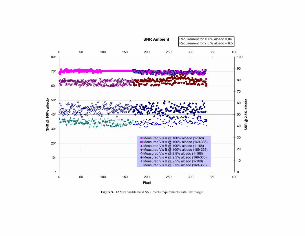
Figure 9. JAMI’s visible band SNR meets requirements with ~8x margin.
SNR Ambient
1
101
201
301
401
501
601
701
801
0 50 100 150 200 250 300 350 400
Pixel
SN
R @
100
% a
lbed
o
0
10
20
30
40
50
60
70
80
90
1000 50 100 150 200 250 300 350 400
SN
R @
2.5
% a
lbed
o
Measured Vis A @ 100% albedo (1-168)Measured Vis A @ 100% albedo (169-336)Measured Vis B @ 100% albedo (1-168)Measured Vis B @ 100% albedo (169-336)Measured Vis A @ 2.5% albedo (1-168)Measured Vis A @ 2.5% albedo (169-336)Measured Vis B @ 2.5% albedo (1-168)Measured Vis B @ 2.5% albedo (169-336)
Requirement for 100% albedo = 84Requirement for 2.5 % albedo = 6.5
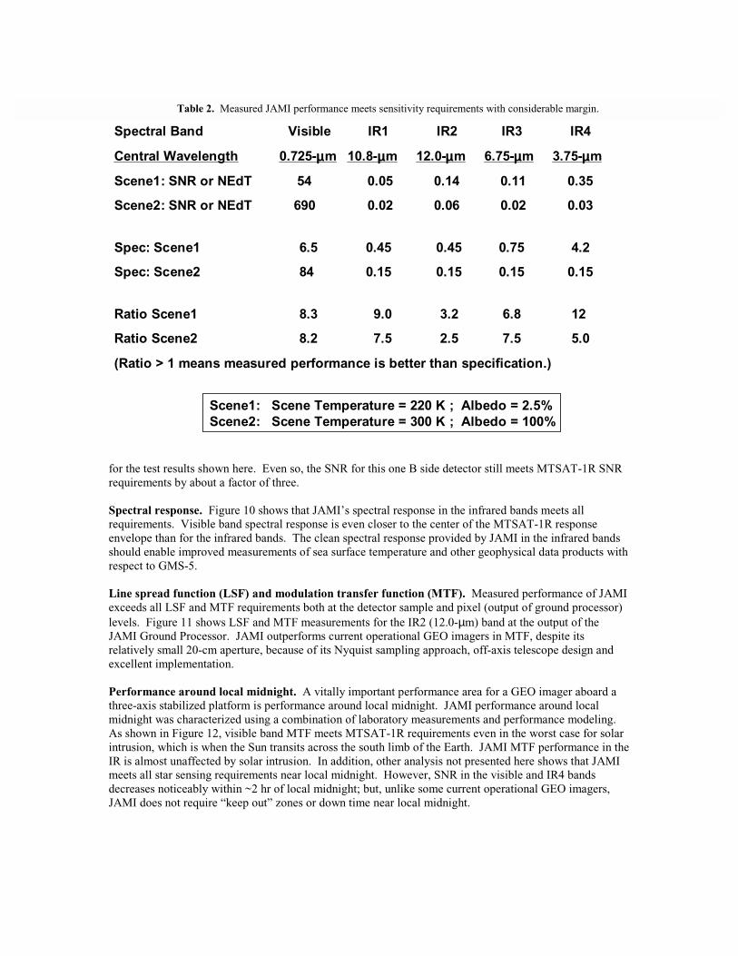
for the test results shown here. Even so, the SNR for this one B side detector still meets MTSAT-1R SNR requirements by about a factor of three. Spectral response. Figure 10 shows that JAMI’s spectral response in the infrared bands meets all requirements. Visible band spectral response is even closer to the center of the MTSAT-1R response envelope than for the infrared bands. The clean spectral response provided by JAMI in the infrared bands should enable improved measurements of sea surface temperature and other geophysical data products with respect to GMS-5. Line spread function (LSF) and modulation transfer function (MTF). Measured performance of JAMI exceeds all LSF and MTF requirements both at the detector sample and pixel (output of ground processor) levels. Figure 11 shows LSF and MTF measurements for the IR2 (12.0-µm) band at the output of the JAMI Ground Processor. JAMI outperforms current operational GEO imagers in MTF, despite its relatively small 20-cm aperture, because of its Nyquist sampling approach, off-axis telescope design and excellent implementation. Performance around local midnight. A vitally important performance area for a GEO imager aboard a three-axis stabilized platform is performance around local midnight. JAMI performance around local midnight was characterized using a combination of laboratory measurements and performance modeling. As shown in Figure 12, visible band MTF meets MTSAT-1R requirements even in the worst case for solar intrusion, which is when the Sun transits across the south limb of the Earth. JAMI MTF performance in the IR is almost unaffected by solar intrusion. In addition, other analysis not presented here shows that JAMI meets all star sensing requirements near local midnight. However, SNR in the visible and IR4 bands decreases noticeably within ~2 hr of local midnight; but, unlike some current operational GEO imagers, JAMI does not require “keep out” zones or down time near local midnight.
Table 2. Measured JAMI performance meets sensitivity requirements with considerable margin.
Spectral Band Visible IR1 IR2 IR3 IR4
Central Wavelength 0.725-µµµµm 10.8-µµµµm 12.0-µµµµm 6.75-µµµµm 3.75-µµµµm
Scene1: SNR or NEdT 54 0.05 0.14 0.11 0.35
Scene2: SNR or NEdT 690 0.02 0.06 0.02 0.03
Spec: Scene1 6.5 0.45 0.45 0.75 4.2
Spec: Scene2 84 0.15 0.15 0.15 0.15
Ratio Scene1 8.3 9.0 3.2 6.8 12
Ratio Scene2 8.2 7.5 2.5 7.5 5.0
(Ratio > 1 means measured performance is better than specification.)
Scene1: Scene Temperature = 220 K ; Albedo = 2.5%Scene2: Scene Temperature = 300 K ; Albedo = 100%

4. PROJECT STATUS
JAMI was delivered to Space Systems/Loral on 2003 June 17. It was installed and aligned on the spacecraft within 5 days of arrival. As of early 2003 August, detailed integration and testing of MTSAT-1R is ongoing and analysis of JAMI test results continues in a few areas, including radiometric calibration.
5. SUMMARY JAMI introduces the next generation of GEO meteorological imager and provides much improved spatial sampling, radiometric sensitivity, Earth coverage and 24-hour observation capability compared with current operational GEO imagers. JAMI was delivered to Space Systems/Loral on 2003 June 17 for integration into the MTSAT-1R system. The instrument was installed and aligned on the spacecraft within 5 days. JAMI reduces risk for future GEO imagers by early implementation of advanced instrument technologies in GEO.
REFERENCES 1. Jeffery J. Puschell, Howard A. Lowe, James W. Jeter, Steven M. Kus, W. Todd Hurt, David Gilman,
David L. Rogers, Roger L. Hoelter and Russ Ravella, “Japanese Advanced Meteorological Imager: a next generation GEO imager for MTSAT-1R,” SPIE Proceedings 4814, pp. 152-161, 2002.
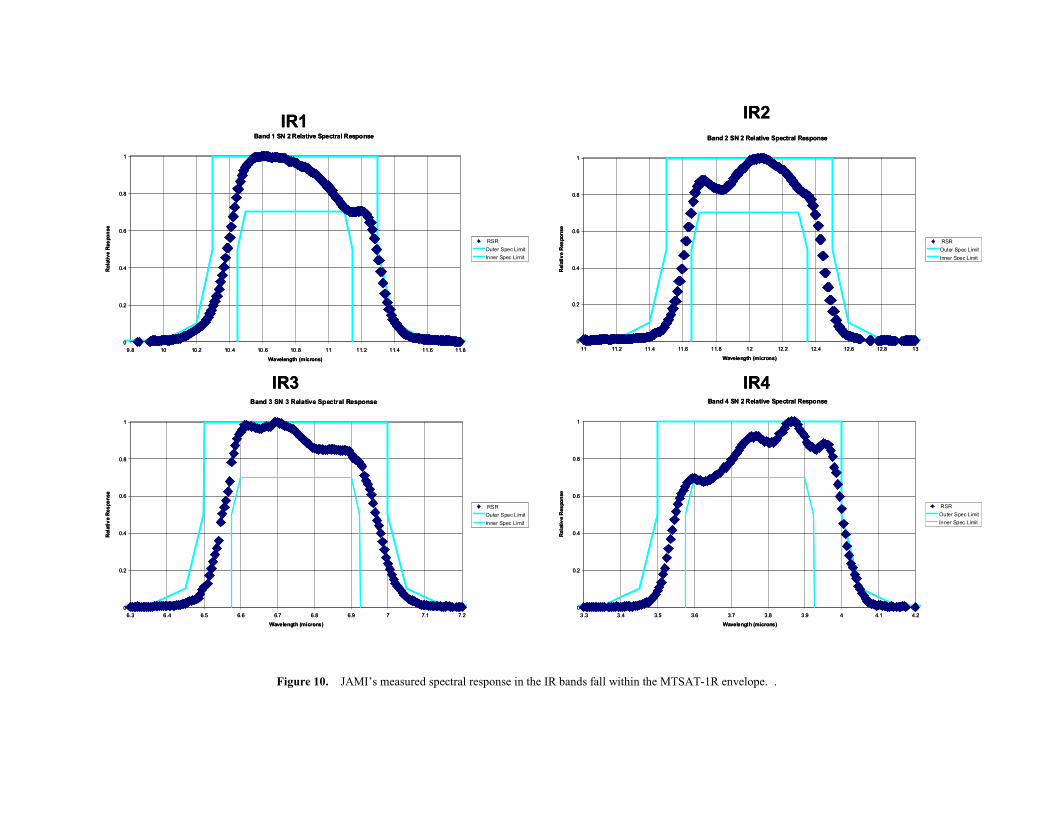
Figure 10. JAMI’s measured spectral response in the IR bands fall within the MTSAT-1R envelope. .
Band 1 SN 2 Relative Spectral Response
0
0.2
0.4
0.6
0.8
1
9.8 10 10.2 10.4 10.6 10.8 11 11.2 11.4 11.6 11.8
Wavelength (microns)
Rel
ativ
e R
espo
nse
RSR
Outer Spec Limit
Inner Spec Limit
IR1Band 2 SN 2 Relative Spectral Response
0
0.2
0.4
0.6
0.8
1
11 11.2 11.4 11.6 11.8 12 12.2 12.4 12.6 12.8 13
Wavelength (microns)
Rel
ativ
e R
espo
nse
RSR
Outer Spec Limit
Inner Spec Limit
IR2
Band 3 SN 3 Relative Spectral Response
0
0.2
0.4
0.6
0.8
1
6.3 6.4 6.5 6.6 6.7 6.8 6.9 7 7.1 7.2
Wavelength (microns)
Rel
ativ
e R
espo
nse
RSR
Outer Spec Limit
Inner Spec Limit
IR4IR3Band 4 SN 2 Relative Spectral Response
0
0.2
0.4
0.6
0.8
1
3.3 3.4 3.5 3.6 3.7 3.8 3.9 4 4.1 4.2
Wavelength (microns)
Rel
ativ
e R
espo
nse
RSR
Outer Spec Limit
Inner Spec Limit

Figure 11. Measured LSF and MTF performance for JAMI meets all MTSAT-1R requirements in all bands, including the IR2 band shown here.
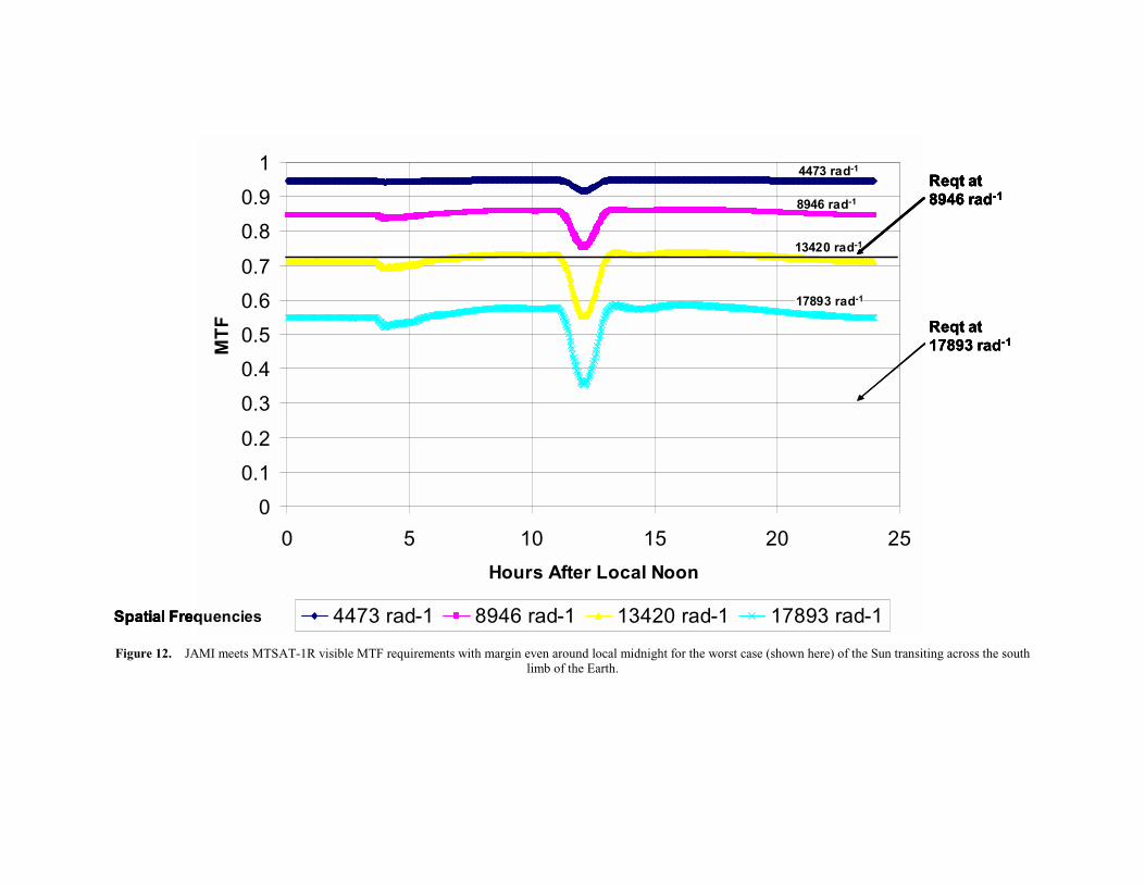
Figure 12. JAMI meets MTSAT-1R visible MTF requirements with margin even around local midnight for the worst case (shown here) of the Sun transiting across the south limb of the Earth.
0
0.1
0.2
0.3
0.4
0.5
0.6
0.7
0.8
0.9
1
0 5 10 15 20 25
Hours After Local Noon
MT
F
4473 rad-1 8946 rad-1 13420 rad-1 17893 rad-1Spatial Frequencies
Reqt at 17893 rad-1
Reqt at 8946 rad-1
13420 rad-1
4473 rad-1
8946 rad-1
17893 rad-1
0
0.1
0.2
0.3
0.4
0.5
0.6
0.7
0.8
0.9
1
0 5 10 15 20 25
Hours After Local Noon
MT
F
4473 rad-1 8946 rad-1 13420 rad-1 17893 rad-1Spatial Frequencies
Reqt at 17893 rad-1
Reqt at 8946 rad-1
0
0.1
0.2
0.3
0.4
0.5
0.6
0.7
0.8
0.9
1
0 5 10 15 20 25
Hours After Local Noon
MT
F
4473 rad-1 8946 rad-1 13420 rad-1 17893 rad-1Spatial Frequencies
Reqt at 17893 rad-1
Reqt at 8946 rad-1Reqt at 8946 rad-1
13420 rad-1
4473 rad-1
8946 rad-1
17893 rad-1


