
ISO 10077-2 validation of HEAT2 v7+v8, revised June 16, 2014
Thermal conductance L2D
, thermal transmittance Uf and linear thermal transmittance Ψ:
ISO 10077 HEAT2 Nodes CPU ISO 10077 HEAT2
Case L2D
W/(mK) L2D
W/(mK) Diff Uf
W/(m2K) U
f W/(m
2K) Diff
D1 0,550±0,007 0,5499
0,5511
47 000
524000
17s
30min
0% 3,22±0,06 3,218 0%
D2 0,263±0,001 0,2643
0,2644
62000
1E6
6s
30min
0,5% 1,44±0,03 1,457 1,2%
D3 0,424±0,006 0,4264 37000 3s 0,6% 2,07±0,06 2,096 1,2%
D4 0,346±0,001 0,3456 76000 3s 0% 1,36±0,01 1,361 0%
D5 0,408±0,007 0,4042 85000 10s 0,9% 2,08±0,08 2,047 -1,6%
D6 0,659±0,008
(***)
0,6588
0,6599
0,6563
61000
460000
98000
37s
22min
0%
0.1%
0.5%
4,67±0,09
4,673
4,647
0%
0.5%
D7 0,285±0,002
(***)
0,2830
0,2827
85000 4s 0,7%
0,8%
1,31±0,03 1,270
1.263
-3,0%
-3,6%
D8 0,181±0,003 0,1805 83000 6s 0% 1,03±0,02* 1,020 0%
D9 0,207±0,001 0,2067 59000 2s 0% 3,64±0,01** 3,627 0%
ISO 10077 HEAT2 Nodes CPU ISO 10077 HEAT2
Case L2D
W/(mK) L2D
W/(mK) Diff Ψ W/(mK)
Ψ W/(mK) Diff
D10 0,481±0,004 0,4854
0,4858
76 000
624000
4s
160s
0,9
%
0,084±0,004 0,0877 4,4
%
EN ISO 10077-2 states that the difference of L2D
should not be more than 3%. HEAT2 gives a
maximum difference of 0,9% and complies to the standard.
The HEAT2 calculations actually use more nodes than needed (according to EN ISO 10211:2007) in
order to get higher accuracy. In fact, about 2000 nodes are sufficient for case D1 to comply with
the EN ISO 10211-2 requirement for mesh sub-division (this will give L2D
= 0.540, i.e. about 2%
difference from 0.5511). Note that HEAT2 calculates each case within a few seconds even with a
large amount of nodes.
- “CPU” is the calculation time on a Intel Core 2 Duo 2,4 GHz.
- Values in blue are calculated using a special version of HEAT2 with 4 million nodes.
- (*) This value should probably be 1,02±0,02 (because 0,181/0,177=1,023).
- (**) This value should probably be 3,63±0,02 (because 0,207/0,057=3,632).

(***) Notes on sloping external boundaries:
We have a comment on how to treat sloping boundaries; see e.g. case D6 and D7.
There is a need to adjust the thermal resistance of a numerical cell lying at a boundary when a
sloping boundary is approximated by steps in order to simulate a boundary condition with a
temperature and a surface resistance, or a given heat flux, correctly. HEAT2 v8 is capable of
handling this automatically, see chapter 4.4 in
http://www.buildingphysics.com/manuals/HEAT2_8_update.pdf
Without this correction, the boundary resistances will be somewhat too low (leading to a somewhat
too high total heat flow. The surface temperatures will be too low on the cold side, and too high on
the warm side.
The difference for the total heat flow is only a few per-mille for the cases D6 and D7, so the
correction here is a bit academic. There could however be cases where the correction can lead to
many per cents difference of the total heat flow (and of course surface temperatures).
We have sent a note about this to the ISO committee.
See comments for cases D6 and D7 below.

Case D1
Input given in pre-processor:
Frame cavities are drawn using the item “Frame cavity” in the material list. Note that coherent
“Frame cavity” rectangles will produce a final cavity, see e.g. the three rectangles marked in red
below (rectangle marked “4, 9, 10” in figure further down). Also note that two points to open
boundary segments is placed here (to be able to give different boundary conditions with R=0.13
and R=0.20):

Generated frame cavity numbers (1-11) and boundary segments (1-12):
Boundary conditions (1-4) specified for boundary segments numbers (1-12):
Frame cavity options dialogue:

Calculated temperatures and isotherms:
Calculated heat flow intensities and equivalent thermal conductivities for the cavities:

Calculated heat flows:
The info log (F12) gives calculated equivalent thermal conductivity for the cavities:
The thermal conductance becomes using the heat flow through the external boundary (see above)
L2D
= 10,998/20=0,5499 W/(mK)
and the thermal transmittance becomes
Uf
= (L2D
-Upbp)/bf = (0,5499-1,030930,19)/0,11=3,218 W/(m2K)
where
Up =1/(0,13+0,04+0,028/0,035)=1,03093 W/(m2K)
To make this calculation please do as follows:
1. Open file ISO10077_D1.dat
2. Start the calculation (press F9)
3. Answer yes on the question “Cavity number 6 lies at a boundary. Do you want to use
twice the equivalent lambda?”. This is a slightly ventilated cavity, see standard.

Case D2
HEAT2 will recognize all 6 cavities, see numbers below. It is enough to draw two “Frame cavity”
rectangles in order to encapsulate cavity 1 and 2, respectively, see rectangles marked in red below.

Note that for the aluminum part with cavities 4 and 6 it is enough to draw one aluminum rectangle
plus 4 “Frame cavity” rectangles (in total 5 drawn rectangles):
These five rectangles added gives:
Alternatively, this could have been made with six drawn aluminum rectangles:

The thermal conductance becomes
L2D
= 5,2862/20=0,2643 W/(mK)
and the thermal transmittance becomes
Uf
= (L2D
-Upbp)/bf = (0,2643-0,547300,19)/0,11=1,457 W/(m2K)
where
Up =1/(0,13+0,04+0,058/0,035)=0,54730 W/(m2K)
To make this calculation please do as follows:
1. Open file ISO10077_D2.dat
2. Start the calculation (press F9)
3. Answer no on the question “Cavity number 2 lies at a boundary. Do you want to use twice
the equivalent lambda?”

Case D3
HEAT2 will recognize all 12 cavities. It is enough to draw one “Frame cavity” in order to
encapsulate cavity 1, see red rectangle below (this rectangle could also have filled the cavity area).

The thermal conductance becomes
L2D
= 8,5274/20=0,4264 W/(mK)
and the thermal transmittance becomes
Uf
= (L2D
-Upbp)/bf = (0,4264-1,030930,19)/0,11=2,096 W/(m2K)
where
Up =1/(0,13+0,04+0,028/0,035)=1,03093 W/(m2K)
To make this calculation please do as follows:
1. Open file ISO10077_D3.dat
2. Start the calculation (press F9)

Case D4
Input:
Generated cavities:

The thermal conductance becomes
L2D
= 6,9122/20=0,3456 W/(mK)
and the thermal transmittance becomes
Uf
= (L2D
-Upbp)/bf = (0,3456-1,030930,19)/0,11=1,361 W/(m2K)
where
Up =1/(0,13+0,04+0,028/0,035)=1,03093 W/(m2K)
To make this calculation please do as follows:
1. Open file ISO10077_D4.dat
2. Start the calculation (press F9)
3. Answer yes on the question “Cavity number 2 lies at a boundary. Do you want to use
twice the equivalent lambda?”

Case D5
Input in pre-processor:
Generated frame cavities:

In this case we have a heat flow mainly in the x-direction for cavity 1, and a heat flow mainly in the
y-direction for cavities 2, 4, 5. Since HEAT2 assumes the same direction for all cavities we need to
make two different calculations. In the first one we state that the heat flow is mainly in the x-
direction. This will give the equivalent thermal conductivity of cavity 1.
To make this calculation please do as follows:
1. Open file ISO10077_D5.dat
2. Start the calculation (press F9)
3.
4. Answer no on the question “Cavity number 1 lies at a boundary. Do you want to use twice
the equivalent lambda?” and yes for cavities 2 and 4.
The info log (press F12) shows that the calculated equivalent thermal conductivity of cavity 1 is
0.0691.
After this we make a new material in the material list with lambda=0.0691 and replaces the area
for cavity 1 with the new material:

This is available here:
1. Open file ISO10077_D5_equivalentTC.dat (this will use the material file
DEFAULT_ISO10077_D5.MTL. Make sure this file exists in the same folder as HEAT2.exe).
2. Start the calculation (press F9) with main direction of heat flow set to y-direction:
3.
4. Answer yes on the question “Cavity number 1 lies at a boundary. Do you want to use
twice the equivalent lambda?” and for cavity 3 (new cavity numbers are assigned).

The thermal conductance becomes
L2D
= 8,0836/20=0,4042 W/(mK)
and the thermal transmittance becomes
Uf
= (L2D
-Upbp)/bf = (0,4042-1,168610,19)/0,089=2,047 W/(m2K)
where
Up =1/(0,13+0,04+0,024/0,035)=1,16861 W/(m2K)

Case D6
Input:
Left: HEAT2 7. Right: HEAT2 8 using polygons.
Generated frame cavities:

Boundary conditions:
[HEAT2 Version 8): First, turn off “Do correction for sloped boundaries”):
The thermal conductance becomes
L2D
= 13,173/20=0,6587 W/(mK)
and the thermal transmittance becomes
Uf
= (L2D
-Upbp)/bf = (0,6587-1,130860,19)/0,095=4,673 W/(m2K)
where
Up =1/(0,13+0,04+0,025/0,035)=1,13086 W/(m2K)
To make this calculation please do as follows:
1. Open file ISO10077_D6.dat
2. Start the calculation (press F9)

(***) Notes on sloping external boundaries:
There is a need to adjust the thermal resistance of a numerical cell lying at a boundary when a
sloping boundary is approximated by steps in order to simulate a boundary condition with a
temperature and a surface resistance, or a given heat flux, correctly. HEAT2 v8 is capable of
handling this automatically, see chapter 4.4 in
http://www.buildingphysics.com/manuals/HEAT2_8_update.pdf
With the correction below (“Do correction for sloped boundaries”) we get the results below.
The thermal conductance becomes
L2D
= 13,126/20=0,6563 W/(mK) (0.4% off ISO 10077-2 value 0,659)
and the thermal transmittance becomes
Uf
= (L2D
-Upbp)/bf = (0,6563-1,130860,19)/0,095=4,647 W/(m2K)
So we get a thermal transmittance of U=4,647 which compared to the ISO value 4,67 differs by
0.5 %.

Case D7
Input:
Left: HEAT2 7. Right: HEAT2 8 using polygons.
Generated frame cavities:

Boundary conditions:
[HEAT2 Version 8): First, turn off “Do correction for sloped boundaries”):
The thermal conductance becomes
L2D
= 5,66/20=0,2830 W/(mK)
and the thermal transmittance becomes
Uf
= (L2D
-Upbp)/bf = (0,2830-1,168610,19)/0,048=1,270 W/(m2K)
where
Up =1/(0,13+0,04+0,024/0,035)=1,16861 W/(m2K)
To make this calculation please do as follows:
1. Open file ISO10077_D7.dat
2. Start the calculation (press F9)

3. Answer yes on the question “Cavity number 1 lies at a boundary. Do you want to use
twice the equivalent lambda?”
The calculated equivalent thermal conductivities for each cavity are shown below:
Cavity Tmax Tmin ha hr lambda
1 1.7388 0.6173 3.125 2.2591 0.0861
2 8.1271 1.9951 1.3362 2.4042 0.1175
3 12.834 7.0669 1.4973 3.1444 0.0775
4 18.127 12.558 1.2939 3.0094 0.1154
5 6.6104 0.4316 1.3395 2.7467 0.1087
6 15.524 13.411 3.9657 3.2042 0.0452
7 13.562 3.2534 1.5888 2.2387 0.1148
8 17.749 13.651 1.3158 2.8785 0.0797
The standard says that “when no other information is available, use Tm= 283 K”. If we change the
option from the default “4 Calculate temperatures iteratively in each cavity” to “2 Use Tmin= 5 and
Tmax=15” we get Tm=283.
Cavity Tmax Tmin ha hr lambda
1 1.7397 0.6177 3.125 2.4926 0.0899
2 8.1267 1.9959 1.57 2.5431 0.1292
3 12.833 7.0662 1.57 3.1566 0.0789
4 18.126 12.557 1.57 2.8548 0.1186
5 6.6098 0.4317 1.57 2.9542 0.1204
6 15.524 13.41 3.9657 3.0675 0.0443
7 13.561 3.2531 1.57 2.2846 0.1156
8 17.749 13.65 1.57 2.7205 0.0815
The thermal conductance becomes
L2D
= 5,6864/20=0,2843 W/(mK)
and the thermal transmittance becomes
Uf
= (L2D
-Upbp)/bf = (0,2843-1,168610,19)/0,048=1,298 W/(m2K)

(***) Notes on sloping external boundaries:
There is a need to adjust the thermal resistance of a numerical cell lying at a boundary when a
sloping boundary is approximated by steps in order to simulate a boundary condition with a
temperature and a surface resistance, or a given heat flux, correctly. HEAT2 v8 is capable of
handling this automatically, see chapter 4.4 in
http://www.buildingphysics.com/manuals/HEAT2_8_update.pdf
We need to make this correction for boundaries 2-273, see picture below. In this case, we cannot
use the automatic option “Do correction for sloped boundaries”, since HEAT2 v8 will identify sloping
boundaries for number 2-273 (which is correct) but also for number 278-281 (which is not correct).
(The automatically identified boundaries for correction are by the way shown in the log, menu
option F12 in HEAT2 v8.)
Therefore, we will make this correction by hand for boundaries 2-273 as described below.
The original boundary conditions are

The new corrected boundary conditions should be (see file ISO10077_D7_CorrectedBC.dat):
Here, we define a new BC type(5) and use the corrected boundary resistance which is calculated
using the total width (w=17 mm) and height (h=29 mm) of the steps 2-273. The correction factor is
(w+h) / = 1,368. The corrected boundary resistance is then 1,368x0.04=0.055.
The calculated thermal conductance becomes then
L2D
= 5,6535/20=0,2827 W/(mK) (0,8% off ISO 10077-2 value 0,285)
and the thermal transmittance becomes
Uf
= (L2D
-Upbp)/bf = (0,2827-1,168610,19)/0,048=1,263 W/(m2K)
So we get a thermal transmittance of U=1.263 which compared to the ISO value 1.31 differs by
3,6%.
Note: The difference for the heat flow using correction or not, is only about 0.1% (0,2830/0,2827) in
this case due to the low boundary resistance (0.04). However, if the thermal boundary resistance
increases, the difference will increase. If we e.g. would have change the external and internal
boundary conditions (using R=0.13 for the sloping boundaries), the difference of the heat flow
would have been 0.2-0.3% instead.

Case D8
Input:
Generated frame cavities:
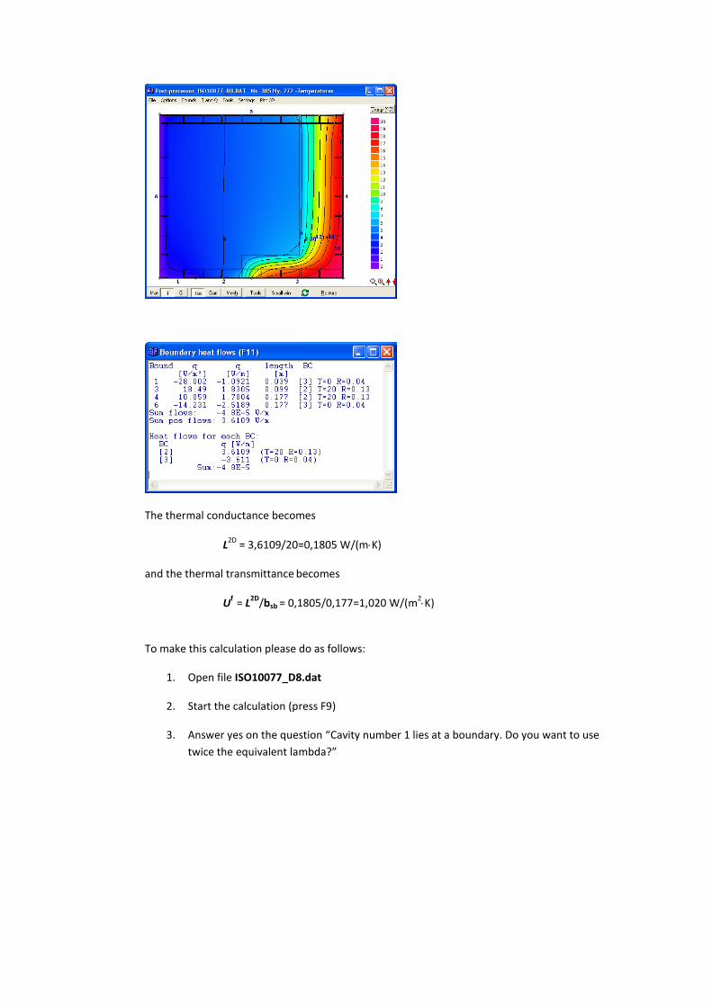
The thermal conductance becomes
L2D
= 3,6109/20=0,1805 W/(mK)
and the thermal transmittance becomes
Uf
= L2D
/bsb = 0,1805/0,177=1,020 W/(m2K)
To make this calculation please do as follows:
1. Open file ISO10077_D8.dat
2. Start the calculation (press F9)
3. Answer yes on the question “Cavity number 1 lies at a boundary. Do you want to use
twice the equivalent lambda?”

Case D9
Input:
Generated frame cavities:
Calculated heat flows:

The thermal conductance becomes
L2D
= 4,1347/20=0,2067 W/(mK)
and the thermal transmittance becomes
Uf
= L2D
/b = 0,2067/0,057=3,627 W/(m2K)
To make this calculation please do as follows:
1. Open file ISO10077_D9.dat
2. Start the calculation (press F9)

Case D10
Input:
Generated frame cavities:

The thermal conductance becomes
L Ψ 2D
= 9,7078/20=0,4854 W/(mK)
and the linear thermal transmittance Ψ becomes
Ψ = L Ψ
2D – Ufbf – Ugbg = 0,4854 - 1,3610.11-1,30510,19=0,0877 W/(mK)
where Uf is taken from case D4 and
Ug =1/(0,13+0,04+0,020/0,033+20,004/1)=1,3051 W/(m2K)
To make this calculation please do as follows:
1. Open file ISO10077_D10.dat
2. Start the calculation (press F9)
3. Answer yes on the question “Cavity number 2 lies at a boundary. Do you want to use
twice the equivalent lambda?”


