
RUGGEDCOM RS416
Installation Guide
06/2016
Preface
Introduction 1
Installing Device 2
Communication Ports 3
Technical Specifications 4
Dimension Drawings 5
Certification 6
RC1018-EN-04
RUGGEDCOM RS416Installation Guide
ii
Copyright © 2016 Siemens Canada Ltd.All rights reserved. Dissemination or reproduction of this document, or evaluation and communication of its contents, is not authorizedexcept where expressly permitted. Violations are liable for damages. All rights reserved, particularly for the purposes of patent application ortrademark registration.This document contains proprietary information, which is protected by copyright. All rights are reserved. No part of this document may bephotocopied, reproduced or translated to another language without the prior written consent of Siemens Canada Ltd..
Disclaimer Of LiabilitySiemens has verified the contents of this document against the hardware and/or software described. However, deviations between the productand the documentation may exist.Siemens shall not be liable for any errors or omissions contained herein or for consequential damages in connection with the furnishing,performance, or use of this material.The information given in this document is reviewed regularly and any necessary corrections will be included in subsequent editions. Weappreciate any suggested improvements. We reserve the right to make technical improvements without notice.
Registered TrademarksRUGGEDCOM™ and ROS™ are trademarks of Siemens Canada Ltd..Other designations in this manual might be trademarks whose use by third parties for their own purposes would infringe the rights of theowner.
Third Party CopyrightsSiemens recognizes the following third party copyrights:• Copyright © 2004 GoAhead Software, Inc. All Rights Reserved.
Security InformationSiemens provides products and solutions with industrial security functions that support the secure operation of plants, machines, equipmentand/or networks. They are important components in a holistic industrial security concept. With this in mind, Siemens' products and solutionsundergo continuous development. Siemens recommends strongly that you regularly check for product updates.For the secure operation of Siemens products and solutions, it is necessary to take suitable preventive action (e.g. cell protection concept) andintegrate each component into a holistic, state-of-the-art industrial security concept. Third-party products that may be in use should also beconsidered. For more information about industrial security, visit http://www.siemens.com/industrialsecurity.To stay informed about product updates as they occur, sign up for a product-specific newsletter. For more information, visit http://support.automation.siemens.com.
WarrantySiemens warrants this product for a period of five (5) years from the date of purchase, conditional upon the return to factory for maintenanceduring the warranty term. This product contains no user-serviceable parts. Attempted service by unauthorized personnel shall render allwarranties null and void. The warranties set forth in this article are exclusive and are in lieu of all other warranties, performance guaranteesand conditions whether written or oral, statutory, express or implied (including all warranties and conditions of merchantability and fitness fora particular purpose, and all warranties and conditions arising from course of dealing or usage or trade). Correction of nonconformities in themanner and for the period of time provided above shall constitute the Seller’s sole liability and the Customer’s exclusive remedy for defectiveor nonconforming goods or services whether claims of the Customer are based in contract (including fundamental breach), in tort (includingnegligence and strict liability) or otherwise.For warranty details, visit www.siemens.com/ruggedcom or contact a Siemens customer service representative.

RUGGEDCOM RS416Installation Guide
iii
Contacting SiemensAddress
Siemens Canada Ltd.Industry Sector300 Applewood CrescentConcord, OntarioCanada, L4K 5C7
Telephone
Toll-free: 1 888 264 0006Tel: +1 905 856 5288Fax: +1 905 856 1995
[email protected]/ruggedcom

RUGGEDCOM RS416Installation Guide
iv

RUGGEDCOM RS416Installation Guide
Table of Contents
v
Table of ContentsPreface ............................................................................................................ vii
Alerts ................................................................................................................................................ viiRelated Documents ............................................................................................................................. viiAccessing Documentation ................................................................................................................... viiTraining ............................................................................................................................................ viiiCustomer Support .............................................................................................................................. viii
Chapter 1Introduction ..................................................................................................... 1
1.1 Feature Highlights ........................................................................................................................ 11.2 Description ................................................................................................................................... 21.3 Precision Time Protocol (PTP) Support ............................................................................................ 4
1.3.1 Supported Time Synchronization Sources ............................................................................. 41.3.2 TTL Outputs ....................................................................................................................... 51.3.3 IEEE 1588 Support ............................................................................................................. 6
Chapter 2Installing Device ............................................................................................... 7
2.1 Mounting the Device .................................................................................................................... 72.1.1 Mounting the Device to a Rack ........................................................................................... 82.1.2 Mounting the Device on a DIN Rail ...................................................................................... 92.1.3 Mounting the Device to a Panel .......................................................................................... 9
2.2 Connecting Power ....................................................................................................................... 102.2.1 Connecting AC Power ....................................................................................................... 112.2.2 Connecting DC Power ....................................................................................................... 122.2.3 Wiring Examples .............................................................................................................. 14
2.3 Connecting the Failsafe Alarm Relay ............................................................................................. 162.4 Grounding the Device ................................................................................................................. 172.5 Connecting to the Device ............................................................................................................ 172.6 Cabling Recommendations .......................................................................................................... 18
Chapter 3Communication Ports ...................................................................................... 19
3.1 Copper Ethernet Ports ................................................................................................................. 193.2 Fiber Optic Ethernet Ports ........................................................................................................... 20

Table of Contents
RUGGEDCOM RS416Installation Guide
vi
3.3 Serial Ports ................................................................................................................................. 213.4 BNC Ports ................................................................................................................................... 243.5 Connecting Multiple RS485 Devices ............................................................................................. 25
Chapter 4Technical Specifications .................................................................................. 27
4.1 Power Supply Specifications ........................................................................................................ 274.2 Failsafe Relay Specifications ......................................................................................................... 274.3 Copper Ethernet Port Specifications .............................................................................................. 284.4 Fiber Optic Ethernet Port Specifications ........................................................................................ 28
4.4.1 10Base-FL Ethernet Optical Specifications .......................................................................... 284.4.2 Fast Ethernet (100 Mbps) Optical Specifications ................................................................. 28
4.5 Serial Port Specifications ............................................................................................................. 294.5.1 Copper Serial Port Specifications ....................................................................................... 294.5.2 Fiber Serial Port Specifications .......................................................................................... 30
4.6 IRIG-B Port Specifications ............................................................................................................. 304.7 Operating Environment ............................................................................................................... 304.8 Mechanical Specifications ............................................................................................................ 31
Chapter 5Dimension Drawings ....................................................................................... 33
Chapter 6Certification .................................................................................................... 37
6.1 Approvals ................................................................................................................................... 376.1.1 CSA ................................................................................................................................. 376.1.2 European Commission (EC) ............................................................................................... 386.1.3 FCC ................................................................................................................................. 386.1.4 FDA/CDRH ........................................................................................................................ 386.1.5 Industry Canada ............................................................................................................... 396.1.6 Other Approvals ............................................................................................................... 39
6.2 EMC and Environmental Type Tests .............................................................................................. 39

RUGGEDCOM RS416Installation Guide
Preface
Alerts vii
PrefaceThis guide describes the RUGGEDCOM RS416. It describes the major features of the device, installation,commissioning and important technical specifications.It is intended for use by network technical support personnel who are responsible for the installation,commissioning and maintenance of the device. It is also recommended for use by network and system planners,system programmers, and line technicians.
AlertsThe following types of alerts are used when necessary to highlight important information.
DANGER!DANGER alerts describe imminently hazardous situations that, if not avoided, will result in death orserious injury.
WARNING!WARNING alerts describe hazardous situations that, if not avoided, may result in serious injury and/orequipment damage.
CAUTION!CAUTION alerts describe hazardous situations that, if not avoided, may result in equipment damage.
IMPORTANT!IMPORTANT alerts provide important information that should be known before performing a procedureor step, or using a feature.
NOTENOTE alerts provide additional information, such as facts, tips and details.
Related DocumentsOther documents that may be of interest include:• ROS User Guide for the RS416
Accessing DocumentationThe latest user documentation for RUGGEDCOM RS416 v is available online at www.siemens.com/ruggedcom. Torequest or inquire about a user document, contact Siemens Customer Support.

Preface
RUGGEDCOM RS416Installation Guide
viii Training
TrainingSiemens offers a wide range of educational services ranging from in-house training of standard courses onnetworking, Ethernet switches and routers, to on-site customized courses tailored to the customer's needs,experience and application.Siemens' Educational Services team thrives on providing our customers with the essential practical skills to makesure users have the right knowledge and expertise to understand the various technologies associated with criticalcommunications network infrastructure technologies.Siemens' unique mix of IT/Telecommunications expertise combined with domain knowledge in the utility,transportation and industrial markets, allows Siemens to provide training specific to the customer's application.For more information about training services and course availability, visit www.siemens.com/ruggedcom orcontact a Siemens Sales representative.
Customer SupportCustomer support is available 24 hours, 7 days a week for all Siemens customers. For technical support or generalinformation, contact Siemens Customer Support through any of the following methods:
OnlineVisit http://www.siemens.com/automation/support-request to submit a Support Request (SR) or checkon the status of an existing SR.
TelephoneCall a local hotline center to submit a Support Request (SR). To locate a local hotline center, visit http://www.automation.siemens.com/mcms/aspa-db/en/automation-technology/Pages/default.aspx .
Mobile AppInstall the Industry Online Support app by Siemens AG on any Android, Apple iOS or Windows mobiledevice and be able to:• Access Siemens' extensive library of support documentation, including FAQs and manuals• Submit SRs or check on the status of an existing SR• Contact a local Siemens representative from Sales, Technical Support, Training, etc.• Ask questions or share knowledge with fellow Siemens customers and the support community

RUGGEDCOM RS416Installation Guide
Chapter 1Introduction
Feature Highlights 1
IntroductionThe RUGGEDCOM RS416 is an industrially hardened serial device server with an integrated, fully managed,Ethernet switch, designed to operate reliably in electrically harsh and climatically demanding environments.Featuring a modular design that can support IEEE 1588 and IRIG-B time synchronization, up to 16 serial ports andup to four Ethernet ports, the RS416 is able to interconnect and synchronize multiple types of intelligent electronicdevices (IEDs).The time source is provided via IEEE 1588 v2 and converted to IRIG-B for distribution to the IEDs via the serialports or dedicated IRIG-B cabling. Each serial port supports standard data communications plus an IRIG-B time-synchronization output. Using the RS416 results in fewer connectivity devices reducing overall system costs andextends the useful life of existing legacy IEDs minimizing capital expenditure for new equipment.The RS416 provides a high level of immunity to electromagnetic interference and heavy electrical surges typicalof environments found in electric utility substations, factory floors or in curb side traffic control cabinets. TheRS416 also features a wide operating temperature range of -40 to 85 °C (-40 to 185 °F) allowing it to be installedin virtually any location.The embedded Rugged Operating System (ROS®) within the RS416 provides advanced layer 2 and layer 3networking functions, advanced cyber security features, and a full array of intelligent functionality for highnetwork availability and manageability. Coupled with the ruggedized hardware design, the RS416 is ideal forcreating mission-critical, real-time, control applications in any harsh environment.
CONTENTS• Section 1.1, “Feature Highlights”• Section 1.2, “Description”• Section 1.3, “Precision Time Protocol (PTP) Support”
Section 1.1
Feature HighlightsSerial Device Server
• Modular design allows for 4, 8, 12, or 16 serial ports• Fully compliant EIA RS422/TIA RS485, RS422, RS232 serial ports (software selectable) with IRIG-B outputs• Serial fiber interface (ST)• Transmit serial data over an IP network• Support for Modbus TCP, DNP 3, TIN serial protocols• Baud rates up to 230 kbps• Raw socket mode allows conversion of any serial protocol• Point-to-point and multi-point modes• Converts Modbus RTU to Modbus• Supports multiple Modbus masters• Converts DNP3.0 to DNP over UDP/TCP
Chapter 1Introduction
RUGGEDCOM RS416Installation Guide
2 Description
Ethernet Ports
• Integrated Ethernet switch• Copper or fiber options• Supports IEEE 1588 v2• Non-blocking, store and forward switching
IRIG-B Option
• Conversion from IEEE 1588 v2• One IRIG-B PWM/PPS Output• One IRIG-B PWM Input• Supports TTL levels• BNC Connectors
IEEE 1588
• Internal clock is synchronized with IEEE 1588 version 2• 100μs time accuracy
Rated for Reliability in Harsh Environments
• Immunity to EMI and heavy electrical surges• Fully independent 2 kV (RMS) isolated serial ports• -40 to 85 °C (-40 to 185 °F) operating temperature (no fans)• 18 AWG galvanized steel enclosure
Universal Power Supply Options
• Fully integrated, dual-redundant (optional) power supplies• Universal high-voltage range: 88-300 VDC or 85-264 VAC• Popular low voltage ranges: 24 VDC (10-36 VDC), 48 VDC (36-59VDC)• Terminal blocks for reliable maintenance free connections• CSA/UL 60950-1 safety approved to 85 °C (185 °F)
Section 1.2
DescriptionThe RS416 features various ports, controls and indicator LEDs on the display panel for connecting, configuring andtroubleshooting the device. The display panel can be located on the rear, front or top of the device, depending onthe mounting configuration.
RUGGEDCOM RS416Installation Guide
Chapter 1Introduction
Description 3
2
5 831
4
7
6
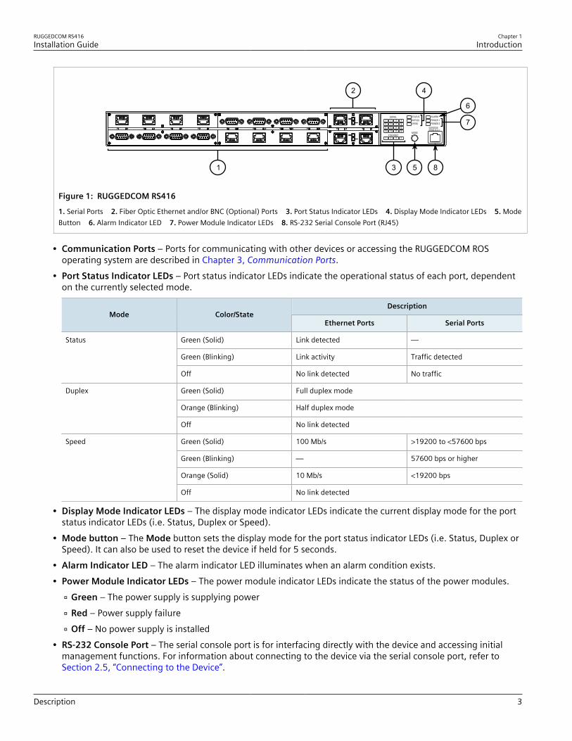
Figure 1: RUGGEDCOM RS416
1. Serial Ports 2. Fiber Optic Ethernet and/or BNC (Optional) Ports 3. Port Status Indicator LEDs 4. Display Mode Indicator LEDs 5. ModeButton 6. Alarm Indicator LED 7. Power Module Indicator LEDs 8. RS-232 Serial Console Port (RJ45)
• Communication Ports – Ports for communicating with other devices or accessing the RUGGEDCOM ROSoperating system are described in Chapter 3, Communication Ports.
• Port Status Indicator LEDs – Port status indicator LEDs indicate the operational status of each port, dependenton the currently selected mode.
DescriptionMode Color/State
Ethernet Ports Serial Ports
Green (Solid) Link detected —
Green (Blinking) Link activity Traffic detected
Status
Off No link detected No traffic
Green (Solid) Full duplex mode
Orange (Blinking) Half duplex mode
Duplex
Off No link detected
Green (Solid) 100 Mb/s >19200 to <57600 bps
Green (Blinking) — 57600 bps or higher
Orange (Solid) 10 Mb/s <19200 bps
Speed
Off No link detected
• Display Mode Indicator LEDs – The display mode indicator LEDs indicate the current display mode for the portstatus indicator LEDs (i.e. Status, Duplex or Speed).
• Mode button – The Mode button sets the display mode for the port status indicator LEDs (i.e. Status, Duplex orSpeed). It can also be used to reset the device if held for 5 seconds.
• Alarm Indicator LED – The alarm indicator LED illuminates when an alarm condition exists.• Power Module Indicator LEDs – The power module indicator LEDs indicate the status of the power modules.
Green – The power supply is supplying power Red – Power supply failure Off – No power supply is installed
• RS-232 Console Port – The serial console port is for interfacing directly with the device and accessing initialmanagement functions. For information about connecting to the device via the serial console port, refer toSection 2.5, “Connecting to the Device”.

Chapter 1Introduction
RUGGEDCOM RS416Installation Guide
4 Precision Time Protocol (PTP) Support
Section 1.3
Precision Time Protocol (PTP) SupportThe Precision Time Protocol (PTP) module adds the ability to provide time synchronization via Ethernet using thePrecision Time Protocol (PTP) and Network Time Protocol (NTP), and to synchronize with an external IRIG-B source.The PTP module features BNC ports for TTL IN and TTL OUT. It also includes an LED to indicate whensynchronization has been achieved.
NOTEThe PTP module can only be installed in slot 5. For more information, refer to Chapter 3,Communication Ports.
TTL
IN
TTL
OUT
1 2
Figure 2: PTP Module
1. TTL OUT Port 2. TTL IN Port
For more information about the BNC ports, refer to Section 3.4, “BNC Ports”.
CONTENTS• Section 1.3.1, “Supported Time Synchronization Sources”• Section 1.3.2, “TTL Outputs”• Section 1.3.3, “IEEE 1588 Support”
Section 1.3.1
Supported Time Synchronization SourcesThe following time synchronization sources are supported by the RS416, with or without the PTP card:
Synchronization Source Without PTP Card With PTP Card
NTP ü ü
IEEE 1588 v2 ü ü
IRIG-B PWM û ü
NTPNTP (Network Time Protocol) is the standard for synchronizing the clocks of computer systems throughout theInternet and is suitable for systems that require accuracies in the order of 1 ms.

RUGGEDCOM RS416Installation Guide
Chapter 1Introduction
TTL Outputs 5
IRIG-B PWMIRIG-B time synchronization is an even older, established, inter-device time synchronization mechanism providingaccuracy in sub-milliseconds.
IEEE 1588IEEE 1588 is designed to provide networked, packet-based time synchronization between different networkingnodes (PTP devices). The RS416 supports PTP v2, which is defined in the IEEE 1588-2008 standard. IEEE 1588 isdesigned to fill a niche not well served by either of the two older, dominant protocols, NTP and IRIG-B. IEEE 1588is also designed for applications that cannot bear the cost of a GPS receiver at each node or for which GPS signalsare inaccessible.The RS416 only supports ordinary clock mode. An ordinary clock can be configured as either a Grandmaster Clock(GM) or a Slave Clock (SC) within the master-slave hierarchy.Every Ethernet port on the RS416 supports IEEE 1588. For more information, refer to Section 1.3.3, “IEEE 1588Support”.
Section 1.3.2
TTL OutputsThe PTP card provides a TTL (Transistor-Transistor Logic) output.The TTL OUT port supports the IRIG-B PWM and PPS signal formats. Enabling/disabling the output port andselecting the signal format is controlled through the RUGGEDCOM ROS operating system.The number of devices that can be connected to the TTL Out port is dependent on the cabling type and length,as well as the input impedances of the devices. The following simplified circuit schematic shows the interfacebetween an IRIG-B source and connected devices.
VS
RS RC
RL/N
321
Figure 3: IRIG-B Simplified Circuit Schematic
1. Source 2. Cabling 3. Device
The maximum number of devices (N) that can be connected to the source is determined by checking if thesource current (IS) required to drive the connected devices is less than the maximum drive current the source canprovide, and verifying that the load voltage (VL) the connected devices see is greater than the minimum requiredvoltage.
Chapter 1Introduction
RUGGEDCOM RS416Installation Guide
6 IEEE 1588 Support
Section 1.3.3
IEEE 1588 SupportRUGGEDCOM RS416 supports various IEEE 1588 time synchronization capabilities and provides synchronization in2-step mode. This mode supports the following clock types:• End-to-End Slave Clock• End-to-End Master Clock• Peer-to-Peer Slave Clock• Peer-to-Peer Master Clock

RUGGEDCOM RS416Installation Guide
Chapter 2Installing Device
Mounting the Device 7
Installing DeviceThe following sections describe how to install the device, including mounting the device, installing/removingmodules, connecting power, and connecting the device to the network.
DANGER!Electrocution hazard – risk of serious personal injury and/or damage to equipment. Before performingany maintenance tasks, make sure all power to the device has been disconnected and waitapproximately two minutes for any remaining energy to dissipate.
WARNING!Radiation hazard – risk of serious personal injury. This product contains a laser system and is classifiedas a CLASS 1 LASER PRODUCT. Use of controls or adjustments or performance of procedures otherthan those specified herein may result in hazardous radiation exposure.
IMPORTANT!This product contains no user-serviceable parts. Attempted service by unauthorized personnel shallrender all warranties null and void.Changes or modifications not expressly approved by Siemens Canada Ltd. could invalidatespecifications, test results, and agency approvals, and void the user's authority to operate theequipment.
IMPORTANT!This product should be installed in a restricted access location where access can only be gained byauthorized personnel who have been informed of the restrictions and any precautions that must betaken. Access must only be possible through the use of a tool, lock and key, or other means of security,and controlled by the authority responsible for the location.
CONTENTS• Section 2.1, “Mounting the Device”• Section 2.2, “Connecting Power”• Section 2.3, “Connecting the Failsafe Alarm Relay”• Section 2.4, “Grounding the Device”• Section 2.5, “Connecting to the Device”• Section 2.6, “Cabling Recommendations”
Section 2.1
Mounting the DeviceThe RS416 is designed for maximum mounting and display flexibility. It can be equipped with connectors thatallow it to be installed in a 48 cm (19 in) rack, 35 mm (1.4 in) DIN rail, or directly on a panel.

Chapter 2Installing Device
RUGGEDCOM RS416Installation Guide
8 Mounting the Device to a Rack
NOTEFor detailed dimensions of the device with either rack, DIN rail or panel hardware installed, refer toChapter 5, Dimension Drawings.
CONTENTS• Section 2.1.1, “Mounting the Device to a Rack”• Section 2.1.2, “Mounting the Device on a DIN Rail”• Section 2.1.3, “Mounting the Device to a Panel”
Section 2.1.1
Mounting the Device to a RackFor rack mount installations, the RS416 can be equipped with rack mount adapters pre-installed at the front orrear of the chassis. Additional adapters are provided to further secure the device in high-vibration or seismicallyactive locations.To secure the device to a standard 48 cm (19 in) rack, do the following:
NOTEThe device can be ordered with the communication ports located at the front or rear of the device.Placing the ports at the rear allows all data and power cabling to be installed and connected at the rearof the rack.
1. Make sure the rack mount adapters are installed on the correct side of the chassis.
NOTEThe chassis features multiple mounting holes, allowing the rack mount adapters to be installed upto 25 mm (1 in) from the face of the device.
3 3
1 2
Figure 4: Rack Mount Adaptors
1. Rear 2. Front 3. Rack Mount Adaptor
2. If required, install adapters on the opposite side of the device to protect from vibrations.3. Insert the device into the rack.
NOTESince heat within the device is channelled to the enclosure, it is recommended that 1 rack-unitof space, or 44 mm (1.75 in), be kept empty above the device. This allows a small amount ofconvectional airflow.
RUGGEDCOM RS416Installation Guide
Chapter 2Installing Device
Mounting the Device on a DIN Rail 9
Forced airflow is not required. However, any increase in airflow will result in a reduction ofambient temperature and improve the long-term reliability of all equipment mounted in the rackspace.
4. Secure the adapters to the rack using the supplied hardware.
Section 2.1.2
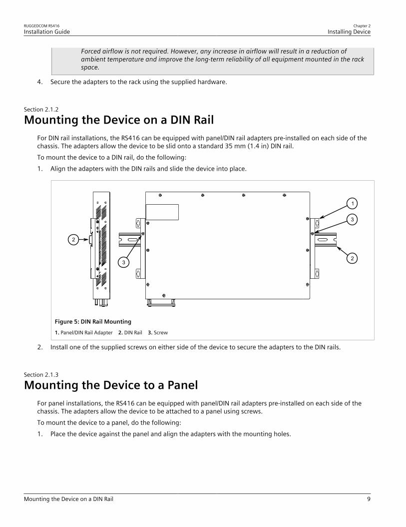
Mounting the Device on a DIN RailFor DIN rail installations, the RS416 can be equipped with panel/DIN rail adapters pre-installed on each side of thechassis. The adapters allow the device to be slid onto a standard 35 mm (1.4 in) DIN rail.To mount the device to a DIN rail, do the following:1. Align the adapters with the DIN rails and slide the device into place.
2
1
2
3
3
Figure 5: DIN Rail Mounting
1. Panel/DIN Rail Adapter 2. DIN Rail 3. Screw
2. Install one of the supplied screws on either side of the device to secure the adapters to the DIN rails.
Section 2.1.3
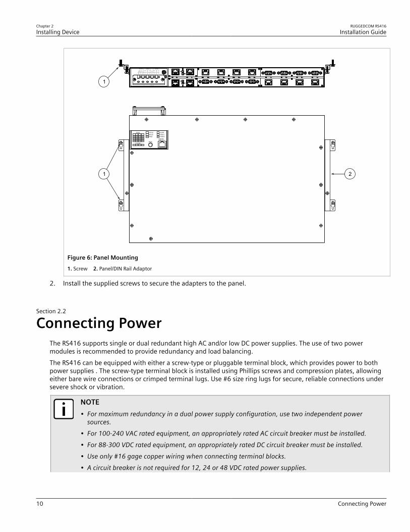
Mounting the Device to a PanelFor panel installations, the RS416 can be equipped with panel/DIN rail adapters pre-installed on each side of thechassis. The adapters allow the device to be attached to a panel using screws.To mount the device to a panel, do the following:1. Place the device against the panel and align the adapters with the mounting holes.
Chapter 2Installing Device
RUGGEDCOM RS416Installation Guide
10 Connecting Power
1
1
2
Figure 6: Panel Mounting
1. Screw 2. Panel/DIN Rail Adaptor
2. Install the supplied screws to secure the adapters to the panel.
Section 2.2
Connecting PowerThe RS416 supports single or dual redundant high AC and/or low DC power supplies. The use of two powermodules is recommended to provide redundancy and load balancing.The RS416 can be equipped with either a screw-type or pluggable terminal block, which provides power to bothpower supplies . The screw-type terminal block is installed using Phillips screws and compression plates, allowingeither bare wire connections or crimped terminal lugs. Use #6 size ring lugs for secure, reliable connections undersevere shock or vibration.
NOTE• For maximum redundancy in a dual power supply configuration, use two independent power
sources.• For 100-240 VAC rated equipment, an appropriately rated AC circuit breaker must be installed.• For 88-300 VDC rated equipment, an appropriately rated DC circuit breaker must be installed.• Use only #16 gage copper wiring when connecting terminal blocks.• A circuit breaker is not required for 12, 24 or 48 VDC rated power supplies.

RUGGEDCOM RS416Installation Guide
Chapter 2Installing Device
Connecting AC Power 11
• It is recommended to provide a separate circuit breaker for each power supply module.• Equipment must be installed according to applicable local wiring codes and standards.
CONTENTS• Section 2.2.1, “Connecting AC Power”• Section 2.2.2, “Connecting DC Power”• Section 2.2.3, “Wiring Examples”
Section 2.2.1
Connecting AC PowerTo connect a high AC power supply to the device, do the following:
CAUTION!Electrical hazard – risk of damage to equipment. Do not connect AC power cables to a DC power supplyterminal block. Damage to the power supply may occur.
CAUTION!Electrical hazard – risk of damage to equipment. Before testing the dielectric strength (HIPOT) in thefield, remove the metal jumper. This metal jumper connects transient suppression circuitry to chassisground and must be removed in order to avoid damage to transient suppression circuitry duringtesting.
NOTEThe terminal block is divided into separate terminals for each internal power supply. Make sure toconnect the external power supply to the appropriate terminals.
1. Remove the terminal block cover.2. If a screw-type terminal block is installed, remove the screws from the appropriate terminals. Use these
screws along with #6 ring lugs to secure the wires to the terminal block.3. Connect the positive wire from the power source to the positive/live (+/L) terminal on the terminal block. For
more information, refer to Section 2.2.3, “Wiring Examples”.

Chapter 2Installing Device
RUGGEDCOM RS416Installation Guide
12 Connecting DC Power
4
21
34
6
5
7
4
6
5
3
6
5
7
4
6
5
Figure 7: Terminal Block Wiring
1. Screw-Type Terminal Block 2. Pluggable Terminal Block 3. Jumper 4. Positive/Live (+/L) Terminal 5. Negative/Neutral (-/N)Terminal (-/N) 6. Surge Ground Terminal 7. Chassis Ground Terminal
4. Connect the negative wire from the power source to the negative/neutral (-/N) terminal on the terminal block.For more information, refer to Section 2.2.3, “Wiring Examples”.
5. Install the supplied metal jumper between terminals 2, 4 and 6 to connect the surge ground terminals tothe chassis ground terminal. The surge ground terminals are used as the ground conductor for all surge andtransient suppression circuitry internal to the unit.
6. Connect the ground terminal on the power source to the chassis ground terminal on the device. For moreinformation, refer to Section 2.4, “Grounding the Device”
DANGER!Electrocution hazard – risk of death, serious personal injury and/or damage to the device. Makesure the supplied terminal block cover is always installed before the device is powered.
7. Install the terminal block cover.
Section 2.2.2
Connecting DC PowerTo connect a single high or low DC power supply to the device, do the following:
CAUTION!Electrical hazard – risk of damage to equipment. Before testing the dielectric strength (HIPOT) in thefield, remove the metal jumper. This metal jumper connects transient suppression circuitry to chassisground and must be removed in order to avoid damage to transient suppression circuitry duringtesting.
RUGGEDCOM RS416Installation Guide
Chapter 2Installing Device
Connecting DC Power 13
NOTEThe screw-type terminal block is installed using Philips screws and compression plates, allowing eitherbare wire connections or crimped terminal lugs. Use #6 size ring lugs for secure, reliable screws, whichmust be removed to make connections.
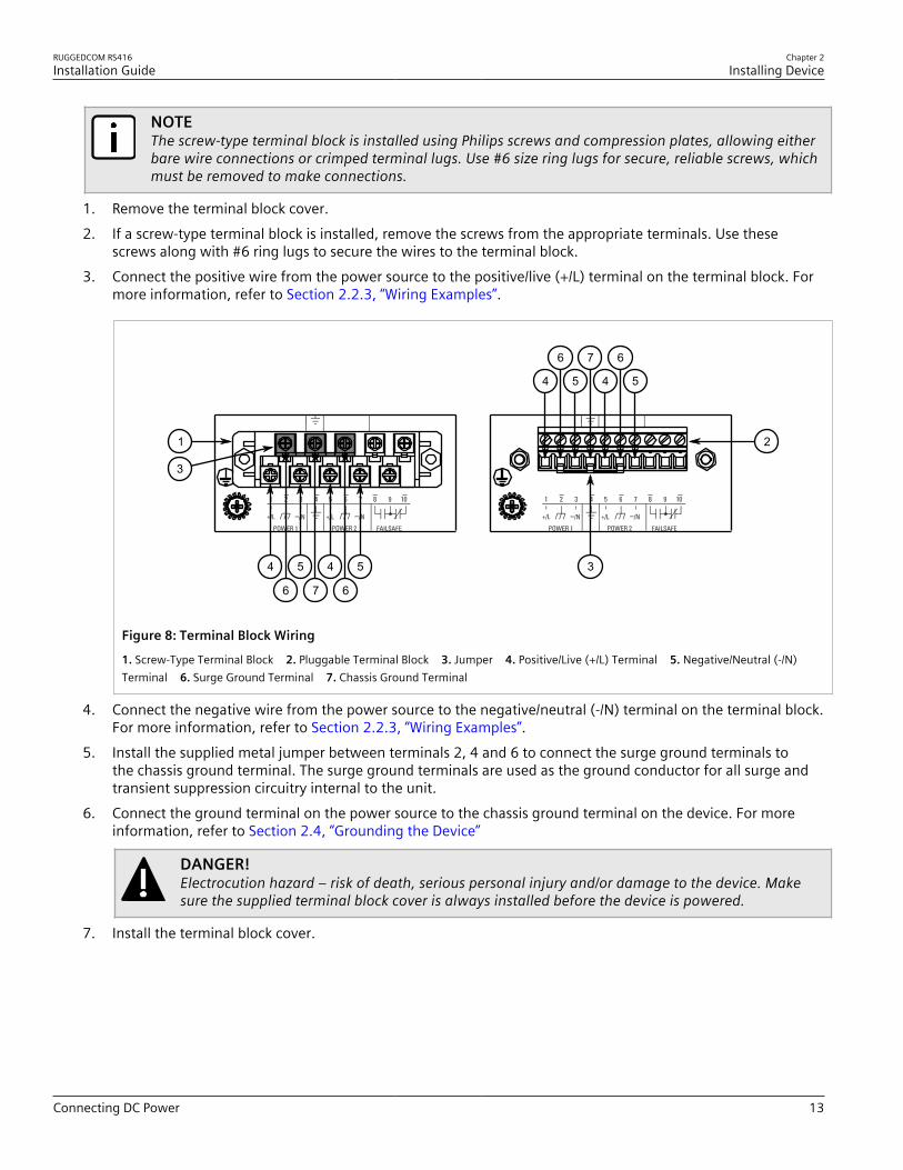
1. Remove the terminal block cover.2. If a screw-type terminal block is installed, remove the screws from the appropriate terminals. Use these
screws along with #6 ring lugs to secure the wires to the terminal block.3. Connect the positive wire from the power source to the positive/live (+/L) terminal on the terminal block. For
more information, refer to Section 2.2.3, “Wiring Examples”.
4
21
34
6
5
7
4
6
5
3
6
5
7
4
6
5
Figure 8: Terminal Block Wiring
1. Screw-Type Terminal Block 2. Pluggable Terminal Block 3. Jumper 4. Positive/Live (+/L) Terminal 5. Negative/Neutral (-/N)Terminal 6. Surge Ground Terminal 7. Chassis Ground Terminal
4. Connect the negative wire from the power source to the negative/neutral (-/N) terminal on the terminal block.For more information, refer to Section 2.2.3, “Wiring Examples”.
5. Install the supplied metal jumper between terminals 2, 4 and 6 to connect the surge ground terminals tothe chassis ground terminal. The surge ground terminals are used as the ground conductor for all surge andtransient suppression circuitry internal to the unit.
6. Connect the ground terminal on the power source to the chassis ground terminal on the device. For moreinformation, refer to Section 2.4, “Grounding the Device”
DANGER!Electrocution hazard – risk of death, serious personal injury and/or damage to the device. Makesure the supplied terminal block cover is always installed before the device is powered.
7. Install the terminal block cover.

Chapter 2Installing Device
RUGGEDCOM RS416Installation Guide
14 Wiring Examples
Section 2.2.3
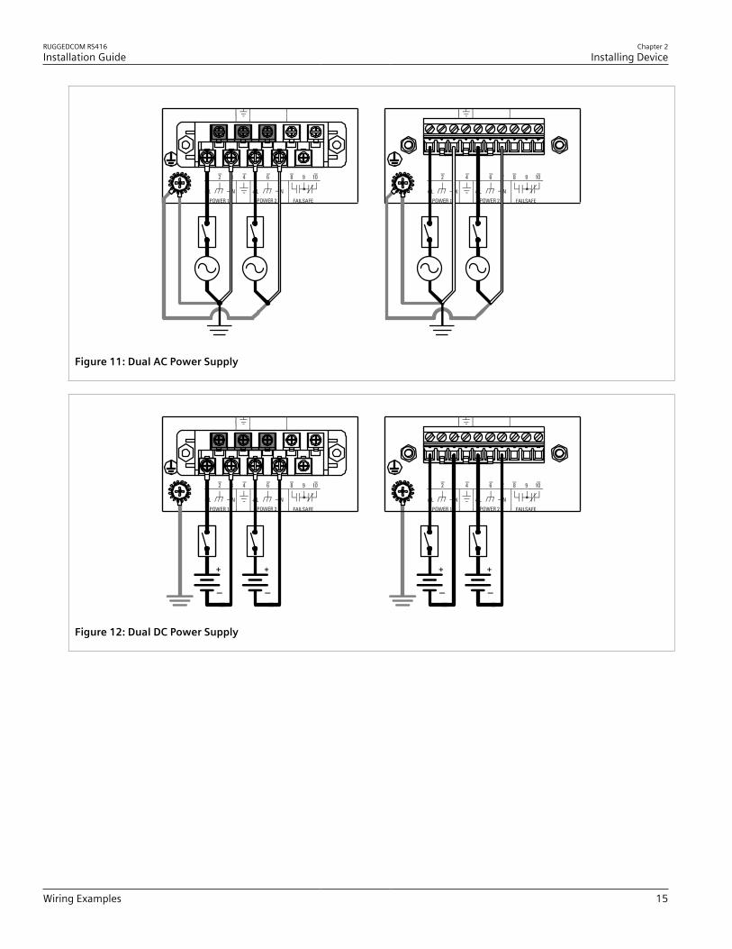
Wiring ExamplesThe following illustrate how to connect power to single and dual power supplies.
Figure 9: Single AC Power Supply
Figure 10: Single DC Power Supply
RUGGEDCOM RS416Installation Guide
Chapter 2Installing Device
Wiring Examples 15
Figure 11: Dual AC Power Supply
Figure 12: Dual DC Power Supply

Chapter 2Installing Device
RUGGEDCOM RS416Installation Guide
16 Connecting the Failsafe Alarm Relay
Figure 13: Dual AC/DC Power Supply
Section 2.3
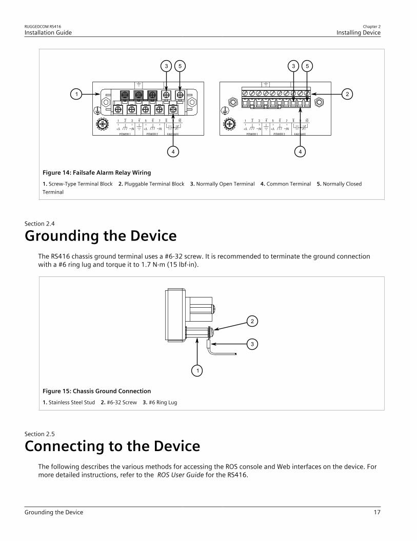
Connecting the Failsafe Alarm RelayThe failsafe relay can be configured to latch based on alarm conditions. The NO (Normally Open) contact is closedwhen the unit is powered and there are no active alarms. If the device is not powered or if an active alarm isconfigured, the relay opens the NO contact and closes the NC (Normally Closed) contact.
NOTEControl of the failsafe relay output is configurable through ROS. One common application for this relayis to signal an alarm if a power failure occurs. For more information, refer to the ROS User Guide forthe RS416.
The following shows the proper relay connections.
RUGGEDCOM RS416Installation Guide
Chapter 2Installing Device
Grounding the Device 17
53 5
21
4 4
3
Figure 14: Failsafe Alarm Relay Wiring
1. Screw-Type Terminal Block 2. Pluggable Terminal Block 3. Normally Open Terminal 4. Common Terminal 5. Normally ClosedTerminal
Section 2.4
Grounding the DeviceThe RS416 chassis ground terminal uses a #6-32 screw. It is recommended to terminate the ground connectionwith a #6 ring lug and torque it to 1.7 N·m (15 lbf·in).
2
1
3
Figure 15: Chassis Ground Connection
1. Stainless Steel Stud 2. #6-32 Screw 3. #6 Ring Lug
Section 2.5
Connecting to the DeviceThe following describes the various methods for accessing the ROS console and Web interfaces on the device. Formore detailed instructions, refer to the ROS User Guide for the RS416.
Chapter 2Installing Device
RUGGEDCOM RS416Installation Guide
18 Cabling Recommendations
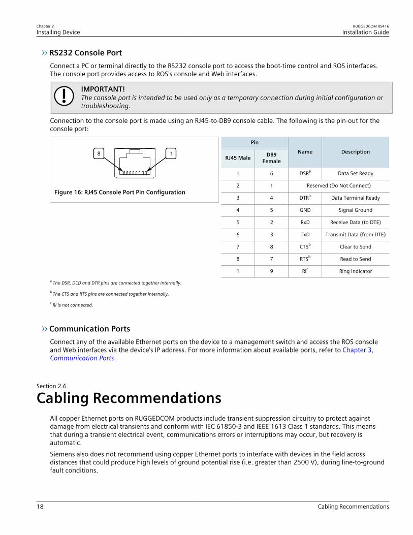
RS232 Console PortConnect a PC or terminal directly to the RS232 console port to access the boot-time control and ROS interfaces.The console port provides access to ROS's console and Web interfaces.
IMPORTANT!The console port is intended to be used only as a temporary connection during initial configuration ortroubleshooting.
Connection to the console port is made using an RJ45-to-DB9 console cable. The following is the pin-out for theconsole port:
8 1
Figure 16: RJ45 Console Port Pin Configuration
Pin
RJ45 Male DB9Female
Name Description
1 6 DSRa Data Set Ready
2 1 Reserved (Do Not Connect)
3 4 DTRa Data Terminal Ready
4 5 GND Signal Ground
5 2 RxD Receive Data (to DTE)
6 3 TxD Transmit Data (from DTE)
7 8 CTSb Clear to Send
8 7 RTSb Read to Send
1 9 RIc Ring Indicatora The DSR, DCD and DTR pins are connected together internally.
b The CTS and RTS pins are connected together internally.
c RI is not connected.
Communication PortsConnect any of the available Ethernet ports on the device to a management switch and access the ROS consoleand Web interfaces via the device's IP address. For more information about available ports, refer to Chapter 3,Communication Ports.
Section 2.6
Cabling RecommendationsAll copper Ethernet ports on RUGGEDCOM products include transient suppression circuitry to protect againstdamage from electrical transients and conform with IEC 61850-3 and IEEE 1613 Class 1 standards. This meansthat during a transient electrical event, communications errors or interruptions may occur, but recovery isautomatic.Siemens also does not recommend using copper Ethernet ports to interface with devices in the field acrossdistances that could produce high levels of ground potential rise (i.e. greater than 2500 V), during line-to-groundfault conditions.

RUGGEDCOM RS416Installation Guide
Chapter 3Communication Ports
Copper Ethernet Ports 19
Communication PortsThe RUGGEDCOM RS416 can be equipped with various types of communication ports to enhance its abilities andperformance.Each communication port type has a specific place in the RUGGEDCOM RS416 chassis.
1
2
3
4
5
6
Figure 17: Port Assignment1. Slot 1 2. Slot 2 3. Slot 3 4. Slot 4 5. Slot 5 6. Slot 6
Slot Type
1 to 4 Serial Ports
5 Fast Ethernet (10/100Base-TX, 10Base-FL or 10/100Base-FX) or IRIG-B BNC Ports
6 Fast Ethernet (10/100Base-TX, 10Base-FL or 10/100Base-FX)
CONTENTS• Section 3.1, “Copper Ethernet Ports”• Section 3.2, “Fiber Optic Ethernet Ports”• Section 3.3, “Serial Ports”• Section 3.4, “BNC Ports”• Section 3.5, “Connecting Multiple RS485 Devices”
Section 3.1
Copper Ethernet PortsThe RS416 supports several 10/100Base-TX Ethernet ports that allow connection to standard Category 5 (CAT-5)unshielded twisted-pair (UTP) cables with RJ45 male connectors. The RJ45 connectors are directly connected tothe chassis ground on the device and can accept CAT-5 shielded twisted-pair (STP) cables.
WARNING!Electric shock hazard – risk of serious personal injury and/or equipment interference. If shieldedcables are used, make sure the shielded cables do not form a ground loop via the shield wire and the
Chapter 3Communication Ports
RUGGEDCOM RS416Installation Guide
20 Fiber Optic Ethernet Ports
RJ45 receptacles at either end. Ground loops can cause excessive noise and interference, but moreimportantly, create a potential shock hazard that can result in serious injury.
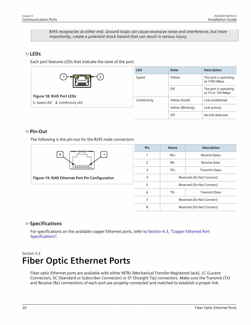
LEDsEach port features LEDs that indicate the state of the port.
1 2
Figure 18: RJ45 Port LEDs1. Speed LED 2. Link/Activity LED
LED State Description
Yellow The port is operatingat 1000 Mbps
Speed
Off The port is operatingat 10 or 100 Mbps
Yellow (Solid) Link established
Yellow (Blinking) Link activity
Link/Activity
Off No link detected
Pin-OutThe following is the pin-out for the RJ45 male connectors:
8 1
Figure 19: RJ45 Ethernet Port Pin Configuration
Pin Name Description
1 RX+ Receive Data+
2 RX- Receive Data-
3 TX+ Transmit Data+
4 Reserved (Do Not Connect)
5 Reserved (Do Not Connect)
6 TX- Transmit Data-
7 Reserved (Do Not Connect)
8 Reserved (Do Not Connect)
SpecificationsFor specifications on the available copper Ethernet ports, refer to Section 4.3, “Copper Ethernet PortSpecifications”.
Section 3.2
Fiber Optic Ethernet PortsFiber optic Ethernet ports are available with either MTRJ (Mechanical Transfer Registered Jack), LC (LucentConnector), SC (Standard or Subscriber Connector) or ST (Straight Tip) connectors. Make sure the Transmit (Tx)and Receive (Rx) connections of each port are properly connected and matched to establish a proper link.

RUGGEDCOM RS416Installation Guide
Chapter 3Communication Ports
Serial Ports 21
21
Figure 20: MTRJ Port1. Tx Connector 2. Rx Connector
21
Figure 21: LC Port1. Tx Connector 2. Rx Connector
21
Figure 22: SC Port1. Tx Connector 2. Rx Connector
21
Figure 23: ST Port1. Tx Connector 2. Rx Connector
For specifications on the available fiber optic Ethernet ports, refer to Section 4.4, “Fiber Optic Ethernet PortSpecifications”.
Section 3.3
Serial PortsThe RS416 supports serial cards with fiber serial ST (Straight Tip) connectors, RS232/RS485/RS422 DB9 serial portsor RS232/RS485/RS422 RJ45 serial ports.Serial DB9 and RJ45 ports can be run in RS232, RS485 or RS422 mode. They can also be ordered with IRIG-B timecode support.
NOTEOn power-up, all serial RJ45 ports default to RS485 mode. Each port can be individually set to RS232,RS485 or RS422 mode through ROS. For more information, refer to the ROS User Guide for the RS416.
NOTEFor information about how to connect devices configured to run in RS485 mode, refer to Section 3.5,“Connecting Multiple RS485 Devices”.
All serial ports feature an LED that indicates the current state of the port.
State Description
Green Link activity detected
Off No link detected
For specifications on serial ports, refer to Section 4.5, “Serial Port Specifications”.The following is the pin-out description for ST, DB9 and RJ45 serial ports:
Chapter 3Communication Ports
RUGGEDCOM RS416Installation Guide
22 Serial Ports
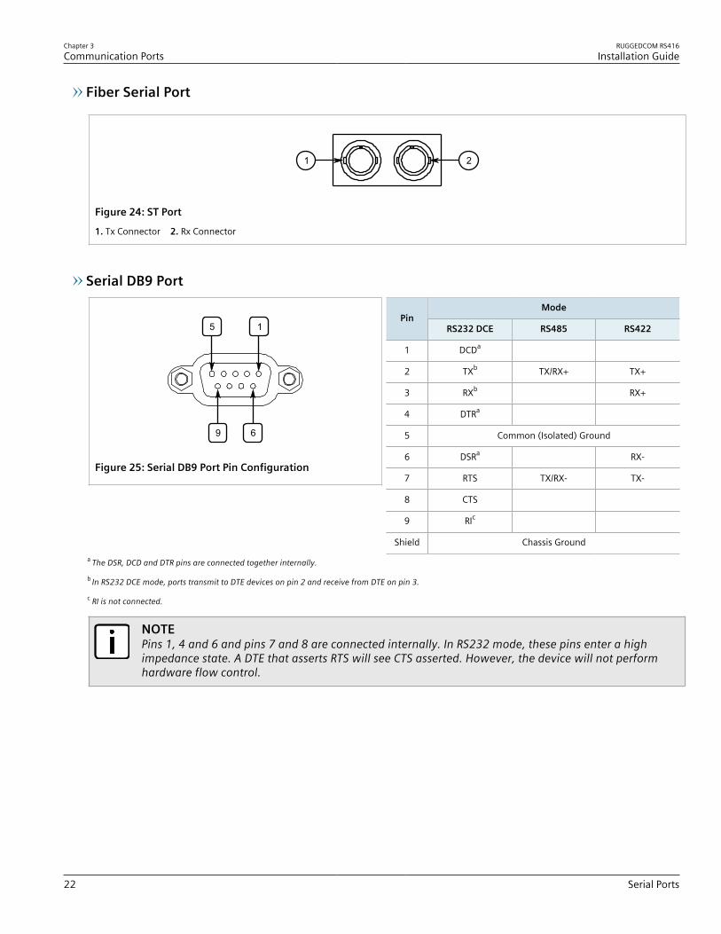
Fiber Serial Port
21
Figure 24: ST Port
1. Tx Connector 2. Rx Connector
Serial DB9 Port
69
5 1
Figure 25: Serial DB9 Port Pin Configuration
ModePin
RS232 DCE RS485 RS422
1 DCDa
2 TXb TX/RX+ TX+
3 RXb RX+
4 DTRa
5 Common (Isolated) Ground
6 DSRa RX-
7 RTS TX/RX- TX-
8 CTS
9 RIc
Shield Chassis Grounda The DSR, DCD and DTR pins are connected together internally.
b In RS232 DCE mode, ports transmit to DTE devices on pin 2 and receive from DTE on pin 3.
c RI is not connected.
NOTEPins 1, 4 and 6 and pins 7 and 8 are connected internally. In RS232 mode, these pins enter a highimpedance state. A DTE that asserts RTS will see CTS asserted. However, the device will not performhardware flow control.
RUGGEDCOM RS416Installation Guide
Chapter 3Communication Ports
Serial Ports 23
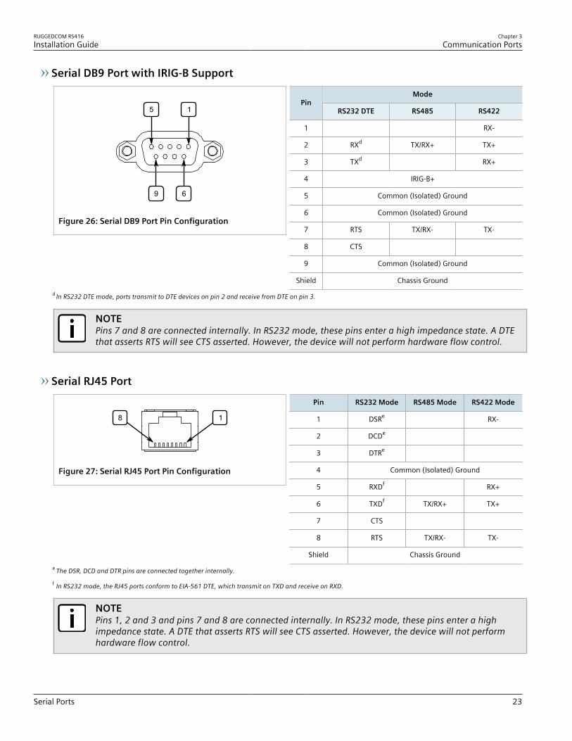
Serial DB9 Port with IRIG-B Support
69
5 1
Figure 26: Serial DB9 Port Pin Configuration
ModePin
RS232 DTE RS485 RS422
1 RX-
2 RXd TX/RX+ TX+
3 TXd RX+
4 IRIG-B+
5 Common (Isolated) Ground
6 Common (Isolated) Ground
7 RTS TX/RX- TX-
8 CTS
9 Common (Isolated) Ground
Shield Chassis Groundd In RS232 DTE mode, ports transmit to DTE devices on pin 2 and receive from DTE on pin 3.
NOTEPins 7 and 8 are connected internally. In RS232 mode, these pins enter a high impedance state. A DTEthat asserts RTS will see CTS asserted. However, the device will not perform hardware flow control.
Serial RJ45 Port
8 1
Figure 27: Serial RJ45 Port Pin Configuration
Pin RS232 Mode RS485 Mode RS422 Mode
1 DSRe RX-
2 DCDe
3 DTRe
4 Common (Isolated) Ground
5 RXDf RX+
6 TXDf TX/RX+ TX+
7 CTS
8 RTS TX/RX- TX-
Shield Chassis Grounde The DSR, DCD and DTR pins are connected together internally.
f In RS232 mode, the RJ45 ports conform to EIA-561 DTE, which transmit on TXD and receive on RXD.
NOTEPins 1, 2 and 3 and pins 7 and 8 are connected internally. In RS232 mode, these pins enter a highimpedance state. A DTE that asserts RTS will see CTS asserted. However, the device will not performhardware flow control.

Chapter 3Communication Ports
RUGGEDCOM RS416Installation Guide
24 BNC Ports
Serial RJ45 Port with IRIG-B Support
8 1
Figure 28: Serial RJ45 Port Pin Configuration
Pin RS232 Mode RS485 Mode RS422 Mode
1 RX-
2 +IRIG-B
3 Common (Isolated) Ground
4 Common (Isolated) Ground
5 RXDg RX+
6 TXDg TX/RX+ TX+
7 CTS
8 RTS TX/RX- TX-
Shield Chassis Groundg In RS232 mode, the RJ45 ports conform to EIA-561 DTE, which transmit on TXD and receive on RXD.
NOTEPins 7 and 8 are connected internally. In RS232 mode, these pins enter a high impedance state. A DTEthat asserts RTS will see CTS asserted. However, the device will not perform hardware flow control.
Section 3.4
BNC PortsThe following BNC ports are available on the PTP module:
TTL
IN
TTL
OUT
1 32
Figure 29: PTP Module1. TTL OUT Port 2. Sync LED 3. TTL IN Port
Port Function
TTL OUT IRIG-B PWM or 1 PPS signaloutput, software selectable
TTL IN TTL-level IRIG-B PWM signal input
Inputs are controlled by RUGGEDCOM ROS and only one can be active at any time. For information aboutactivating an input, refer to the RUGGEDCOM ROS User Guide for the RS416.The color of the Sync LED on the front panel of the PTP module indicates the status of the incoming timing signal:• Green – Signal locked• Amber/Yellow – Holdover (GPS lock has been achieved, but the receiver no longer sees the minimum number
of required satellites)• Red – Error• Off – No signal detected
RUGGEDCOM RS416Installation Guide
Chapter 3Communication Ports
Connecting Multiple RS485 Devices 25
Section 3.5
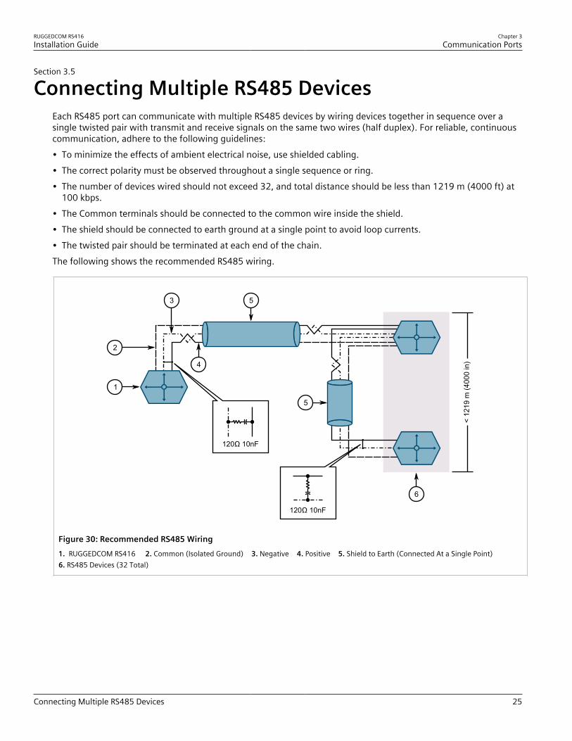
Connecting Multiple RS485 DevicesEach RS485 port can communicate with multiple RS485 devices by wiring devices together in sequence over asingle twisted pair with transmit and receive signals on the same two wires (half duplex). For reliable, continuouscommunication, adhere to the following guidelines:• To minimize the effects of ambient electrical noise, use shielded cabling.• The correct polarity must be observed throughout a single sequence or ring.• The number of devices wired should not exceed 32, and total distance should be less than 1219 m (4000 ft) at
100 kbps.• The Common terminals should be connected to the common wire inside the shield.• The shield should be connected to earth ground at a single point to avoid loop currents.• The twisted pair should be terminated at each end of the chain.The following shows the recommended RS485 wiring.
< 12
19 m
(40
00 in
)
120Ω 10nF
120Ω 10nF
1
2
3 5
5
6
4
Figure 30: Recommended RS485 Wiring1. RUGGEDCOM RS416 2. Common (Isolated Ground) 3. Negative 4. Positive 5. Shield to Earth (Connected At a Single Point) 6. RS485 Devices (32 Total)

RUGGEDCOM RS416Installation Guide
Chapter 3Communication Ports
Connecting Multiple RS485 Devices 26

RUGGEDCOM RS416Installation Guide
Chapter 4Technical Specifications
Power Supply Specifications 27
Technical SpecificationsThis section provides important technical specifications related to the device and available modules.
CONTENTS• Section 4.1, “Power Supply Specifications”• Section 4.2, “Failsafe Relay Specifications”• Section 4.3, “Copper Ethernet Port Specifications”• Section 4.4, “Fiber Optic Ethernet Port Specifications”• Section 4.5, “Serial Port Specifications”• Section 4.6, “IRIG-B Port Specifications”• Section 4.7, “Operating Environment”• Section 4.8, “Mechanical Specifications”
Section 4.1
Power Supply SpecificationsInput Range
Power Supply TypeMinimum Maximum
Internal FuseRatinga b Isolation Maximum Power
Consumptionc
12 VDC
24 VDC10 VDC 36 VDC 6.3 A(F)
48 VDC 36 VDC 59 VDC 3.15 A(T)
1.5 kVDC
HI (125/250 VDC)d 88 VDC 300 VDC
HI (110/230 VAC)d 85 VAC 264 VAC2 A(T) 4 kVAC, 5.5 kVDC
25 W
a (F) denotes fast-acting fuse
b (T) denotes time-delay fuse.
c Power consumption varies based on configuration. 10/100Base-TX ports consume roughly 1 W less than fiber optic ports.
d The HI power supply is the same power supply for both AC and DC.
Section 4.2
Failsafe Relay SpecificationsMaximum Switching Voltage Rated Switching Current
30 VAC 0.3 A, 1.0 A
80 VDC 0.3
Chapter 4Technical Specifications
RUGGEDCOM RS416Installation Guide
28 Copper Ethernet Port Specifications
Section 4.3
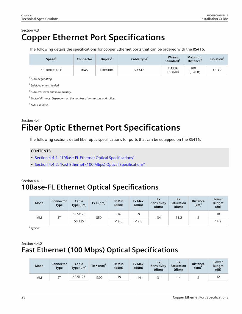
Copper Ethernet Port SpecificationsThe following details the specifications for copper Ethernet ports that can be ordered with the RS416.
Speede Connector Duplexe Cable Typef WiringStandardg
MaximumDistanceh Isolationi
10/100Base-TX RJ45 FDX/HDX > CAT-5 TIA/EIAT568A/B
100 m(328 ft) 1.5 kV
e Auto-negotiating.
f Shielded or unshielded.
g Auto-crossover and auto-polarity.
h Typical distance. Dependent on the number of connectors and splices.
i RMS 1 minute.
Section 4.4
Fiber Optic Ethernet Port SpecificationsThe following sections detail fiber optic specifications for ports that can be equipped on the RS416.
CONTENTS• Section 4.4.1, “10Base-FL Ethernet Optical Specifications”• Section 4.4.2, “Fast Ethernet (100 Mbps) Optical Specifications”
Section 4.4.1
10Base-FL Ethernet Optical Specifications
Mode ConnectorType
CableType (µm) Tx λ (nm)j Tx Min.
(dBm)Tx Max.(dBm)
RxSensitivity
(dBm)
RxSaturation
(dBm)
Distance(km)j
PowerBudget
(dB)
62.5/125 -16 -9 18MM ST
50/125850
-19.8 -12.8-34 -11.2 2
14.2j Typical.
Section 4.4.2
Fast Ethernet (100 Mbps) Optical Specifications
Mode ConnectorType
CableType (μm) Tx λ (nm)k Tx Min.
(dBm)Tx Max.(dBm)
RxSensitivity
(dBm)
RxSaturation
(dBm)
Distance(km)k
PowerBudget
(dB)
MM ST 62.5/125 1300 -19 -14 -31 -14 2 12

RUGGEDCOM RS416Installation Guide
Chapter 4Technical Specifications
Serial Port Specifications 29
Mode ConnectorType
CableType (μm) Tx λ (nm)k Tx Min.
(dBm)Tx Max.(dBm)
RxSensitivity
(dBm)
RxSaturation
(dBm)
Distance(km)k
PowerBudget
(dB)
50/125 -22.5 8.5
62.5/125 -19 12MM SC
50/1251300
-22.5-14 -31 -14 2
8.5
62.5/125 -19 12MM MTRJ
50/1251300
-22.5-14 -31 -14 2
8.5
SM ST 9/125 1300 -15 -8 -32 -3 20 17
SM SC 9/125 1300 -15 -8 -31 -7 20 16
SM LC 9/125 1300 -15 -8 -34 -7 20 19
SM LC 9/125 1300 -15 -8 -34 -7 20 19
SM SC 9/125 1300 -5 0 -34 -3 50 29
SM LC 9/125 1300 -5 0 -35 3 50 30
SM SC 9/125 1300 0 5 -37 0 90 37
SM LC 9/125 1300 0 5 -37 0 90 37
MTRJ 62.5/125 -19 12MM
LC 50/1251300
-22.5-14 -31 -14 2
8.5k Typical.
Section 4.5
Serial Port SpecificationsThis section details specifications for ports that can be equipped on the RS416.
CONTENTS• Section 4.5.1, “Copper Serial Port Specifications”• Section 4.5.2, “Fiber Serial Port Specifications”
Section 4.5.1
Copper Serial Port SpecificationsBaud Rate Connector Isolation
1200 to 230400 kbps DB9 2.5 kV
1200 to 230400 kbps RJ45 2.5 kV
1200 to 230400 kbps DB9 2.5 kV
1200 to 230400 kbps RJ45 2.5 kV
Chapter 4Technical Specifications
RUGGEDCOM RS416Installation Guide
30 Fiber Serial Port Specifications
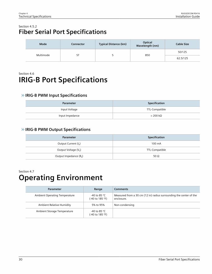
Section 4.5.2
Fiber Serial Port Specifications
Mode Connector Typical Distance (km) OpticalWavelength (nm) Cable Size
50/125Multimode ST 5 850
62.5/125
Section 4.6
IRIG-B Port Specifications
IRIG-B PWM Input Specifications
Parameter Specification
Input Voltage TTL-Compatible
Input Impedance > 200 kΩ
IRIG-B PWM Output Specifications
Parameter Specification
Output Current (Is) 100 mA
Output Voltage (Vs) TTL-Compatible
Output Impedance (Rs) 50 Ω
Section 4.7
Operating EnvironmentParameter Range Comments
Ambient Operating Temperature -40 to 85 °C(-40 to 185 °F)
Measured from a 30 cm (12 in) radius surrounding the center of theenclosure.
Ambient Relative Humidity 5% to 95% Non-condensing
Ambient Storage Temperature -40 to 85 °C(-40 to 185 °F)

RUGGEDCOM RS416Installation Guide
Chapter 4Technical Specifications
Mechanical Specifications 31
Section 4.8
Mechanical SpecificationsParameter Value
Dimensions Refer to Chapter 5, Dimension Drawings
Weight 4.5 kg (10 lbs)
Ingress Protection IP40 (1 mm or 0.04 in objects)
Enclosure 18 AWG Galvanized Steel

RUGGEDCOM RS416Installation Guide
Chapter 4Technical Specifications
Mechanical Specifications 32

RUGGEDCOM RS416Installation Guide
Chapter 5Dimension Drawings
33
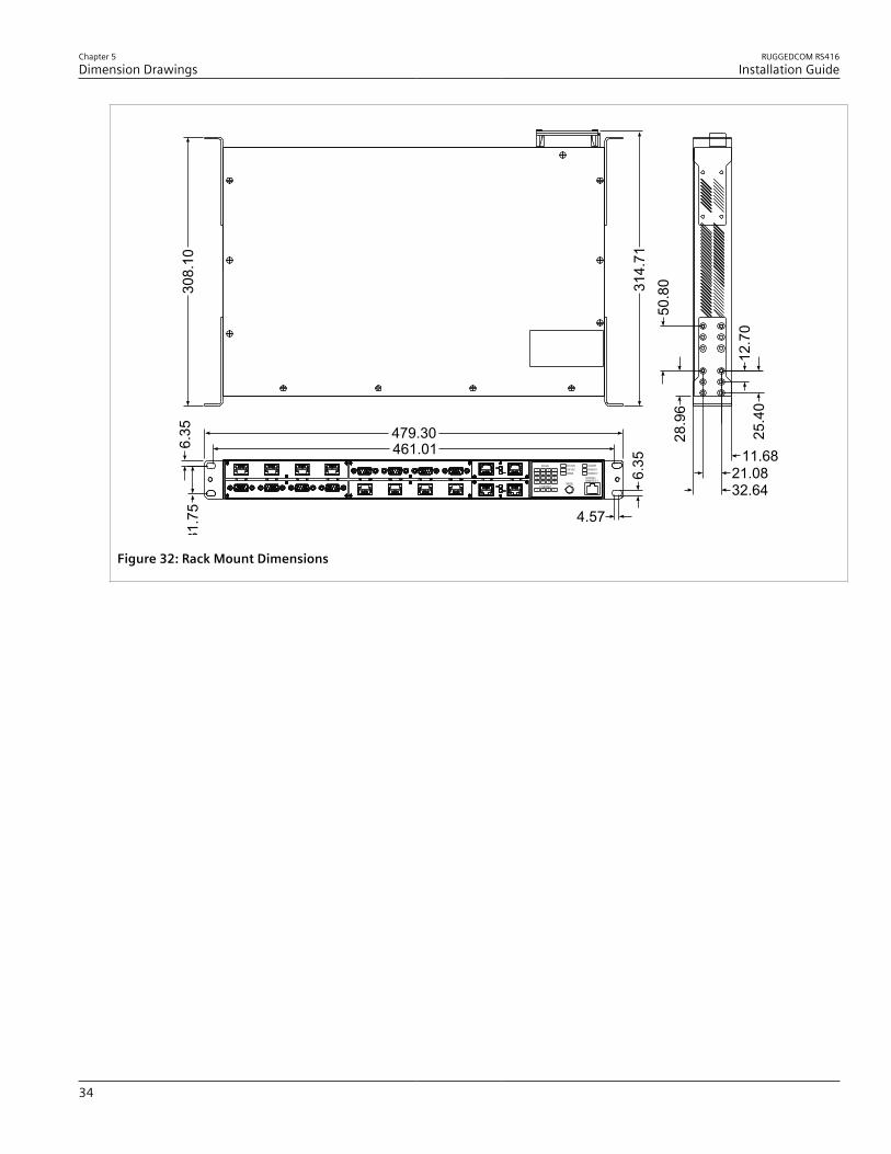
Dimension DrawingsNOTEAll dimensions are in millimeters, unless otherwise stated.
303.
28
44.4
528
5.24
438.15
Figure 31: Overall Dimensions
Chapter 5Dimension Drawings
RUGGEDCOM RS416Installation Guide
34
314.
71
28.9
6
11.6821.0832.64
25.4
0
50.8
0
12.7
0
479.30461.01
6.35
4.57
31.7
56.
3530
8.10
Figure 32: Rack Mount Dimensions

RUGGEDCOM RS416Installation Guide
Chapter 5Dimension Drawings
35
MODE
STATUS
SPEEDDUPLEX
ALARM
POWER2POWER1
57600-N-8-1CONSOLE
1234
5678
1112 910
1314151617181920212223242526272829303132
11.7
159.
812
5.5
80.0
158.
012
7.5
10.47.4
486.4476.3 38
.951
.6
285.
513
4.3
84.1
Figure 33: Panel and DIN Rail Mount Dimensions

RUGGEDCOM RS416Installation Guide
Chapter 5Dimension Drawings
36

RUGGEDCOM RS416Installation Guide
Chapter 6Certification
Approvals 37
CertificationThe RUGGEDCOM RS416 device has been thoroughly tested to guarantee its conformance with recognizedstandards and has received approval from recognized regulatory agencies.
CONTENTS• Section 6.1, “Approvals”• Section 6.2, “EMC and Environmental Type Tests”
Section 6.1
ApprovalsThis section details the standards to which the RUGGEDCOM RS416 complies.
CONTENTS• Section 6.1.1, “CSA”• Section 6.1.2, “European Commission (EC)”• Section 6.1.3, “FCC”• Section 6.1.4, “FDA/CDRH”• Section 6.1.5, “Industry Canada”• Section 6.1.6, “Other Approvals”
Section 6.1.1
CSAThis device meets the requirements of the following Canadian Standards Association (CSA) standards undercertificate 16.70023156:• CAN/CSA-C22.2 No. 60950-1
Information Technology Equipment - Safety - Part 1: General Requirements (Bi-National standard, with UL60950-1)
• UL 60950-1Information Technology Equipment - Safety - Part 1: General Requirements
The device is marked with a CSA symbol that indicates compliance with both Canadian and U.S. requirements.
C US

Chapter 6Certification
RUGGEDCOM RS416Installation Guide
38 European Commission (EC)
Section 6.1.2
European Commission (EC)This device is declared by Siemens Canada Ltd. to comply with essential requirements and other relevantprovisions of the following EC directives:• EN 60950-1
Information Technology Equipment – Safety – Part 1: General Requirements• EN 61000-6-2
Electromagnetic Compatibility (EMC) – Part 6-2: Generic Standards – Immunity for Industrial Environments• EN 55022
Information Technology Equipment - Radio Disturbance Characteristics - Limits and Methods of Measurement• EN 50581
Technical Documentation for the Assessment of Electrical and Electronic Products with Respect to the Restrictionof Hazardous Substances
• EN 60825-1Safety of Laser Products – Equipment Classification and Requirements
The device is marked with a CE symbol and can be used throughout the European community.
A copy of the CE Declaration of Conformity is available from Siemens Canada Ltd.. For contact information, referto the section called “Contacting Siemens ”.
Section 6.1.3
FCCThis device has been tested and found to comply with the limits for a Class A digital device pursuant to Part 15 ofthe FCC Rules. These limits are designed to provide reasonable protection against harmful interference when theequipment is operated in a commercial environment.This device generates, uses and can radiate radio frequency energy and, if not installed and used in accordancewith the instruction manual, may cause harmful interference to radio communications. Operation of thisequipment in a residential area is likely to cause harmful interference in which case the user will be required tocorrect the interference on his own expense.
Section 6.1.4
FDA/CDRHThis device meets the requirements of the following U.S. Food and Drug Administration (FDA) standard:• Title 21 Code of Federal Regulations (CFR) – Chapter I – Sub-chapter J – Radiological Health

RUGGEDCOM RS416Installation Guide
Chapter 6Certification
Industry Canada 39
Section 6.1.5
Industry CanadaThis device is declared by Siemens Canada Ltd. to meet the requirements of the following Industry Canadastandard:• CAN ICES-3 (A)/NMB-3 (A)
Section 6.1.6
Other ApprovalsThis device meets the requirements of the following additional standards:• IEEE 1613
IEEE Standard Environmental and Testing Requirements for Communications Networking Devices in ElectricPower Substations
• IEC 61850-3Communication Networks and Systems for Power Utility Automation - Part 3: General Requirements
• IEC 61000-6-2Electromagnetic Compatibility (EMC) – Part 6-2: Generic Standards – Immunity for Industrial Environments
Section 6.2
EMC and Environmental Type TestsThe RS416 has passed the following EMC and environmental tests.
IEC 61850-3 Type Tests
Test Description Test Levels Severity Levels
Enclosure Contact ± 8 kV 4IEC 61000-4-2 ESD
Enclosure Air ± 15 kV 4
IEC 61000-4-3 Radiated RFI Enclosure ports 20 V/m Notea
Signal ports ± 4 kV @ 2.5 kHz Notea
DC Power ports ± 4 kV 4
AC Power ports ± 4 kV 4
IEC 61000-4-4 Burst (Fast Transient)
Earthground ports
± 4 kV 4
Signal ports 2 kV 3
DC Power ports ± 2 kV line-to-earth, ± 1 kV line-to-line 3
IEC 61000-4-5 Surge
AC Power ports ± 4 kV line-to-earth, ± 2 kV line-to-line 4
Signal ports 10 V 3IEC 61000-4-6 Induced (Conducted) RFI
DC Power ports 10 V 3

Chapter 6Certification
RUGGEDCOM RS416Installation Guide
40 EMC and Environmental Type Tests
Test Description Test Levels Severity Levels
AC Power ports 10 V 3
Earthground ports
10 V 3
100 A/m NoteaIEC 61000-4-8 Magnetic Field Enclosure ports
1000 A/m for 3 s 5
DC Power ports 30% for 0.1 s, 100% for 0.05 sIEC 61000-4-29IEC 61000-4-11
Voltage Dips and Interrupts
AC Power ports 30% for 1 period, 100% for 5periods, 100% for 250 periods
Signal ports 2.5 kV common, 1 kVdifferential mode @ 1 MHz
3
DC Power ports 2.5 kV common, 1 kVdifferential mode @ 1 MHz
3
IEC 61000-4-12 Damped Oscillatory
AC Power ports 2.5 kV common, 1 kVdifferential mode @ 1 MHz
3
Signal ports 30 V Continuous, 300 V for 1 s 4IEC 61000-4-16 Mains Frequency Voltage
DC Power ports 30 V Continuous, 300 V for 1 s 4
IEC 61000-4-17 Ripple on DC Power Supply DC Power ports ± 15% 4
Signal ports 2 kVAC (Fail-Safe Relay output)
DC Power ports 1.5 kV
Dielectric Strength
AC Power ports 2 kV
Signal ports 5 kV (Fail-Safe Relay Output)
DC Power ports 5 kV
IEC 60255-5
HV Impulse
AC Power ports 5 kVa Siemens specified severity level.
IEEE 1613 EMC Immunity Type Tests
NOTEThe RS416 meets Class 2 requirements for an all-fiber configuration and Class 1 requirements forcopper ports.
Description Test Levels
Enclosure Contact ± 8 kVESD
Enclosure Air ± 15 kV
Radiated RFI Enclosure ports 35 V/m
Signal ports ± 4 kV @ 2.5 kHz
DC Power ports ± 4 kV
AC Power ports ± 4 kV
Fast Transient
Earth ground ports ± 4 kV

RUGGEDCOM RS416Installation Guide
Chapter 6Certification
EMC and Environmental Type Tests 41
Description Test Levels
Signal ports 2.5 kV common mode @ 1MHz
DC Power ports 2.5 kV common and differential mode @ 1MHz
Oscillatory
AC Power ports 2.5 kV common and differential mode @ 1MHz
Signal ports 5 kV (Failsafe Relay)
DC Power ports 5 kV
HV Impulse
AC Power ports 5 kV
Signal ports 2 kVAC (Failsafe Relay)
DC Power ports 1.5 kV
Dielectric Strength
AC Power ports 2 kV
Environmental Type Tests
Test Description Test Levels Severity Levels
IEC 60068-2-1 Cold Temperature Test Ad -40 °C (-40 °F), 16 Hours
IEC 60068-2-2 Dry Heat Test Bd 85 °C (185 °F), 16 Hours
IEC 60068-2-30 Humidity (DampHeat, Cyclic)
Test Db 95% (non-condensing),55 °C (131 °F), 96 hours
IEC 60068-2-6 Vibration 2 g @ 10-150 Hz Class 2
IEC 60068-2-27 Shock 30 g @ 11 ms Class 2

RUGGEDCOM RS416Installation Guide
Chapter 6Certification
EMC and Environmental Type Tests 42


