Download - Internet-based collaborative product design with assembly features and virtual design spaces
Internet-based collaborative product design with assembly features andvirtual design spaces
N. Shyamsundar*, Rajit Gadh
Department of Mechanical Engineering, University of Wisconsin, Madison, WI 53706, USA
Received 1 November 1999; revised 15 September 2000; accepted 15 October 2000
Abstract
Typically, during product design collaborating, designers share design data and assembly models. However, due to the limited bandwidth
of the Internet transfer of detailed CAD based assembly models is slow. Therefore, tools based on polygonized representations of assembly
models have been utilized during collaborative design. These models are primarily used for visualization, which is an important activity
during modeling. However, providing the designers with the ability to perform real-time geometric modi®cation, assembly constraints
speci®cation and concurrent design of different components/sub-assemblies will enable designers to collaborate effectively during design.
This paper presents a new geometric representation called the AREP and a prototypical system (cPAD) that uses this representation, which
implements the collaboration paradigm by supporting these activities. q 2001 Elsevier Science Ltd. All rights reserved.
Keywords: Collaboration design; Assembly models; Form features
1. Introduction
In a typical product design scenario, different components
or sub-assemblies of the product are designed by different
groups of designers at geographically different locations.
This is because, original equipment manufacturers (OEM)
are out-sourcing engineering activities performed internally
[1,2] to remain competitive. However, due to outsourcing of
the design activity speci®cation con¯icts can arise. By effec-
tively collaborating, these con¯icts can be resolved early in
the design stage thereby reducing the product development
lead-time and manufacturing cost to a large extent [3].
To accomplish this, a compact and comprehensive repre-
sentation that effectively disseminates product assembly
design knowledge, and a tool that provides an integrated
interface through which this knowledge can be accessed
and manipulated is required. Such a representation and
tool is the focus of this paper.
With the increasing availability of the Internet/Intranet,
tools that aid designers to share design data and models over
the Internet utilize a variety of Internet and web based utili-
ties such as e-mail, web pages, Internet-based conferencing
utilities and utilities for collaborative viewing of 3-D
product models. This indirect approach of integrating design
tools makes collaboration a tedious, unorganized and extre-
mely error-prone. Developing a representation scheme and
an internet-centric product assembly design tool based on
this representation is the focus of this paper. This tool
provides the ability to directly share assembly models and
design knowledge encapsulated in terms of features during
distributed design of a product assembly, thereby establish-
ing a seamless, integrated and collaborative design space.
The representation proposed in this research utilizes the
concept of features to minimize the size of the assembly
model and at the same time encapsulate assembly
constraints in the form of interface assembly features. The
use of interface assembly features provides the designers
with a new paradigm for collaboration, which can ensure
that the components and sub-assemblies designed by differ-
ent designers are compatible with each other.
A typical scenario for application of the direct approach is
when an auto-manufacturer out-sources both the design and
manufacturing of a sub-system, such as an engine. Prior to
outsourcing, the manufacturer typically would request a cost
estimate from the supplier. The manufacturer therefore
provides the supplier with an approximate shape of the
model (the virtual design space, a concept that will be
explained in detail later in the paper) that is produced before
the detailed model of an engine. In addition, the manufacturer
provides the speci®cations of `mating assembly features' or
Computer-Aided Design 33 (2001) 637±651
COMPUTER-AIDEDDESIGN
0010-4485/01/$ - see front matter q 2001 Elsevier Science Ltd. All rights reserved.
PII: S0010-4485(01)00069-0
www.elsevier.com/locate/cad
* Corresponding author. Tel.: 11-608-262-9058; fax: 11-608-265-2316.
E-mail addresses: [email protected] (N. Shyamsundar),
[email protected] (R. Gadh).
`hard' points (the interface assembly features, a concept that
will be explained in detail later in the paper) where the engine
is attached to the rest of the chassis of the automobile. The
virtual design space, which the supplier receives, is the
envelope within which the supplier must design the engine
such that the engine design satis®es the speci®cations of the
mating assembly features that interact with the rest of the
product.
2. Related research
This section reviews the previous work on collaborative
design as well as assembly representation. Research has
been performed to demonstrate the feasibility of collabora-
tive design and deduce the requirements for collaborative
design in the Madefast program [4]. The Madefast program
validated the Internet as an information infrastructure for
collaborative engineering. Based on a study conducted by
Cutkosky et al. [5] the authors conclude that in: (a) distrib-
uted design several groups communicate utilizing a prede-
®ned protocol and (b) during concurrent engineering
integration of multitude of models required for the complex
design process must be considered. The authors suggest a
¯exible representation scheme that can represent the
product in varying levels of detail. A review of current
practices and future trends in the development of a network
based computer aided design framework has been presented
by Regli [6]. The author presents two technologies that are
key to the development of network centric data: (a) CAD
browsers currently implemented based on the use of visua-
lization tools based on polygonized models and (b) Internet-
aware CAD data were hyper links to related design data are
embedded. Max®eld et al. [7] discuss a virtual environment
that allows real time collaboration between designers for
assembly modeling using constraints. In the research work
by Roy et al. [8], collaborating designers create concept
models of parts, and iterate until the part design is complete
prior to manufacturing analysis of the part.
Floriani et al. [9] and Requicha and Whalen [10] present
representations for modeling assemblies. Cutkosky et al.
[11], Shah and Rogers [12] and Fazio et al. [13] utilize
assembly representations that are based on ®xed dictionary
of assembly features. The results of their investigations indi-
cate that utilizing the assembly features for design can effec-
tively capture the information necessary for assembly tasks.
Wedeking [14] proposes that assembly design start with a
spatial envelope of the assembly, which is revised as the
iterative design process proceeds. Considerable work on
assembly representation for assembly sequencing [15,16],
and disassembly sequencing [17,18] has been done.
In summary, existing collaborative tools for assembly
modeling typically utilize polygonized models or detailed
CAD model of the assembly. Polygonized model support
only visualization and do not support activities like
geometric modi®cation and constraint speci®cation between
components. There are several existing boundary-based or
feature-based based assembly representation schemes,
which have the drawback that they are detailed representa-
tions and are therefore not compact enough for transmitting
over the limited bandwidth of the Internet during collabora-
tions. The representations utilized during assembly analysis
are typically optimized for the algorithm that analyzes the
assembly and cannot be directly utilized for collaborative
design. These representation schemes abstract out from the
detailed assembly model information required for assembly
analysis and store it in a suitable data structure and hence are
not suitable for collaborative design.
Therefore, this research utilizes an intelligent polygo-
nized format that maintains pointers to the corresponding
entities in the detailed CAD model of assembly. Previous
research has validated the Internet as the medium for colla-
borative engineering providing designers access to comput-
ing resources. Also a need for tools that will provide an
integrated interface for designers to access online engineer-
ing information and services is also reported in existing
literature.
3. Requirements for a representation to supportcollaborative product design
To enumerate the requirements for a representation
scheme to support collaborative assembly modeling, it is
necessary to examine the framework for a collaborative
assembly-modeling tool. Typically, collaboration requires
the sharing of programs and data between the designers
utilizing networked computers. Distributed architectures
have to address critical design issues that are not present
in stand-alone systems [19] like, locating programs and
data, establishing and maintaining inter program communi-
cation, coordinating and synchronizing distributed applica-
tions, and failure recovery and security. A model that
satis®es these requirements is a `client±server' model [19]
which is utilized in this research.
Currently the best medium to accomplish collaboration is
the Internet/Intranet. Due to the widespread availability of
the high bandwidth Internet design teams can communicate
design data. Though the available bandwidth of the Internet
may be in Megabits or in some cases Gigabits the effective
bandwidth [20] available is much lesser. During collabora-
tion several teams are working on different products and
utilize the same network that effectively reduces the avail-
able bandwidth. Also as the bandwidth increases, develop-
ment and use of Internet centric applications also increase
thereby reducing the effective bandwidth. Therefore, in
spite of development of high bandwidth networks the effec-
tive bandwidth available is limited and its usage needs to be
optimized.
Summarizing from the previous discussion, the product
assembly representation scheme should be: (a) compact, (b)
encapsulate the assembly design speci®c information and
N. Shyamsundar, R. Gadh / Computer-Aided Design 33 (2001) 637±651638
(c) provide a uni®ed approach to represent the product
model on the server as well as the client.
4. De®nitions and assembly representation
The assembly representation (AREP) consists of four
classes of information, namely: (a) a directed acyclic
graph, DAG (called an assembly hierarchy graph, AHG)
that speci®es the hierarchy in the assembly, (b) relational
graphs, (c) assembly level information and (d) information
related to an individual unit within an assembly (called an
Assembly Unit or AU which can be components or sub-
assemblies or envelopes).
From existing literature on assembly representations the
assembly hierarchy can be a ¯at relational representation
capturing the geometric and functional relations between
components or a hierarchical relational representation relat-
ing components and sub-assemblies or two sub-assemblies.
A hierarchical relational representation (HR) is more ef®-
cient for representing the assemblies as compared to a ¯at
representation.
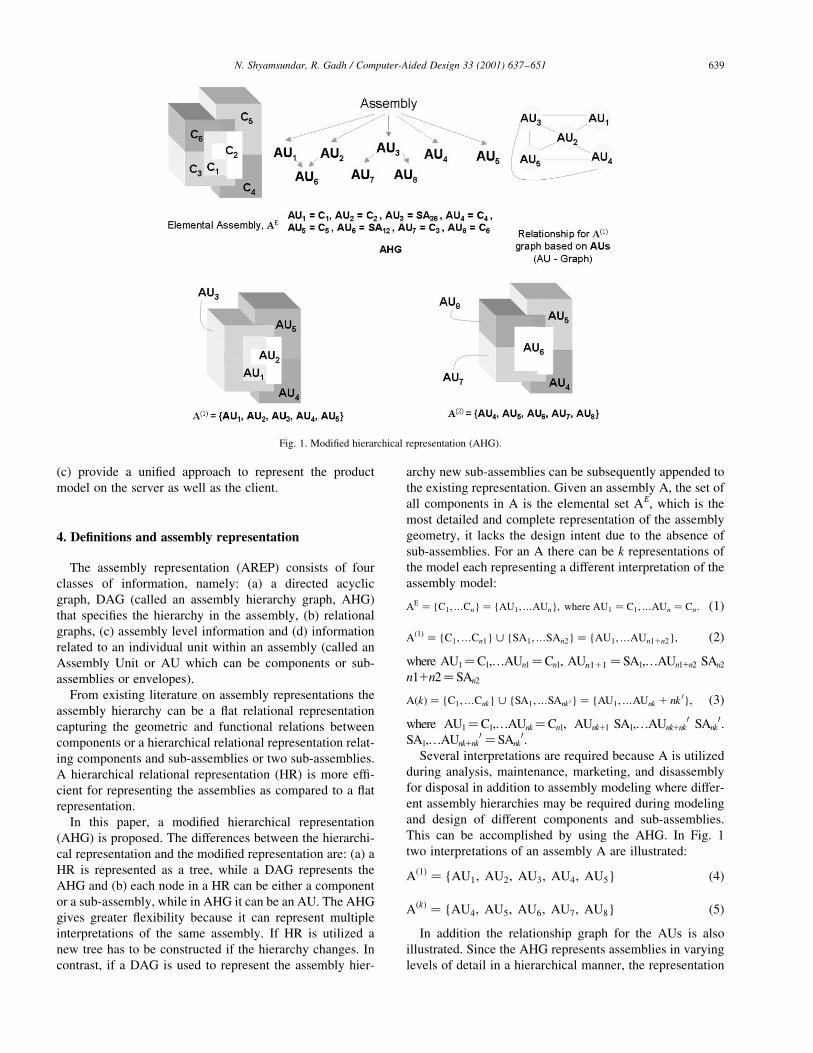
In this paper, a modi®ed hierarchical representation
(AHG) is proposed. The differences between the hierarchi-
cal representation and the modi®ed representation are: (a) a
HR is represented as a tree, while a DAG represents the
AHG and (b) each node in a HR can be either a component
or a sub-assembly, while in AHG it can be an AU. The AHG
gives greater ¯exibility because it can represent multiple
interpretations of the same assembly. If HR is utilized a
new tree has to be constructed if the hierarchy changes. In
contrast, if a DAG is used to represent the assembly hier-
archy new sub-assemblies can be subsequently appended to
the existing representation. Given an assembly A, the set of
all components in A is the elemental set AE, which is the
most detailed and complete representation of the assembly
geometry, it lacks the design intent due to the absence of
sub-assemblies. For an A there can be k representations of
the model each representing a different interpretation of the
assembly model:
AE � {C1;¼Cn} � {AU1;¼AUn}; where AU1 � C1;¼AUn � Cn: �1�
A�1� � {C1;¼Cn1} < {SA1;¼SAn2} � {AU1;¼AUn11n2}; �2�where AU1�C1,¼AUn1�Cn1, AUn111 � SA1,¼AUn11n2 SAn2
n11n2� SAn2
A�k� � {C1;¼Cnk} < {SA1;¼SAnk 0} � {AU1;¼AUnk 1 nk 0}; �3�where AU1�C1,¼AUnk�Cn1, AUnk11 SA1,¼AUnk1nk
0 SAnk0.
SA1,¼AUnk1nk0 � SAnk
0.Several interpretations are required because A is utilized
during analysis, maintenance, marketing, and disassembly
for disposal in addition to assembly modeling where differ-
ent assembly hierarchies may be required during modeling
and design of different components and sub-assemblies.
This can be accomplished by using the AHG. In Fig. 1
two interpretations of an assembly A are illustrated:
A�1� � {AU1; AU2; AU3; AU4; AU5} �4�
A�k� � {AU4; AU5; AU6; AU7; AU8} �5�In addition the relationship graph for the AUs is also
illustrated. Since the AHG represents assemblies in varying
levels of detail in a hierarchical manner, the representation
N. Shyamsundar, R. Gadh / Computer-Aided Design 33 (2001) 637±651 639
Fig. 1. Modi®ed hierarchical representation (AHG).
supports assemblies with a large number of components.
This makes the representation scalable.
Class 2 information consists of a graph in which the nodes
represent AU and the edges represent relationships between
AUs. The relation represented by the edge can be based on
geometric entities, like faces, or other higher-level abstrac-
tions, for example, form features consisting of relations
between AUs. Derivation of this graph is explained in detail
in the subsequent sections.
The assembly level information (Class 3) is the number of
AUs contained in the assembly, list of AU forming sub-
assemblies. The AU level information (Class 4) includes a
representation of AU and related information explained in
the subsequent section.The following section explains the
derivation of the AU graph (Class 2), which in this case is an
assembly feature relation graph (AFRG).
4.1. Assembly features
Shah and Mantyla [21] de®ne a component feature as a
property (for e.g. a blind hole) of a single component.
Some of the de®nitions of assembly features presented in
the literature are listed below.
² An assembly feature is an association between two form
features on different parts, i.e. geometry that belongs to
different parts, expressed in a canonical form [12].
² A feature is any geometric or non-geometric attribute of a
discrete part whose existence or whose dimensions are
relevant to the product's or part's function, manufacture,
engineering, analysis, use, etc. or whose availability as a
primitive or operation facilitates the design process. An
assembly feature is the elementary relation between
components extended with some assembly information
[13].
² Grouping of various feature types to de®ne assembly
relations, such as mating conditions, part relative position
and orientation, various kinds of ®ts and kinematic rela-
tions [21].
In this paper an assembly feature is de®ned as a property
of an AU with respect to (or in the context of) other compo-
nent(s), which provides assembly related information rele-
vant to the design, manufacture or function of the product
assembly. Assembly features can be classi®ed into rela-
tional assembly features and assembly form features. Rela-
tional features indicate a speci®c relation between two
geometric features (GF), which can be form features or
geometric entities like the axis or a surface of revolution.
For example, joints, spatial positioning of one component
with respect to the other and clearances are relation assem-
bly features. Also, certain shape features belonging to two
components can be joined together to form another shape
feature (for example, a peg or a hole) and these are called as
assembly form features. These are two basic types of assem-
bly features. These two features can be combined to form a
derived type called the combination features.
In this paper an assembly feature is denoted by AFri;j;k,
where AF is the rth assembly feature of AUi and AUj, AUk.
If AFri;j is a binary relational assembly feature, a feature
which relates the geometric feature GFui on AUi and GFv
j
on AUj by a relation C. If AF ki;j is a form assembly feature,
then the combination of the form features GFui on AUi and
GFvj on AUj have a speci®c geometric or topological prop-
erty. The same concept of relational and form features can
be generalized to relations involving more than two
geometric features. A feature that is a combination of a
form feature as well as a relational feature is a combination
feature.
4.2. Specifying assembly features
In this paper, an assembly feature de®nition language
(AFDL) is utilized to specify these constraints. The voca-
bulary of AFDL consists of geometric features (GFs), rela-
tional constraints, and form constraints. In this paper, a GF
is assumed to consist of a group of faces on an AU. The
relational constraints (denoted by C) include mating, align-
ment and offset of two faces which are typically used to
orient one AU with respect to another. The form constraints
(denoted by < #) involve speci®cation of relational con-
straints between two GFs to result in a speci®c shape or
form, typically used to satisfy some functional aspect of
the assembly or to be combined with additional relational
constraints to result in a combination assembly feature.
The syntax for de®ning a relational AF is GF ui C
GF jv¼and for a form AF is GFu
q < #: GFvr . Since GF is
de®ned in terms of faces belonging to an AU. Let GFui �
{Fa; Fb; Fc} and GFv
j � F¼a ; F¼
b ; F¼c }. Then AFk
i;j which is
GFui CGF v
j can represented by its elemental relations in
terms of the faces as {(Fa Ca F ¼a ), (Fb Cb F ¼
b ), (Fc Cc
F ¼c )}. Therefore, to specify an AF the GFs should be speci-
®ed ®rst and then the elemental relationships, which are
denoted by Ca, Cb, Cc (in the previous example) need to
be speci®ed. It is to be noted that the order of the corre-
sponding faces belonging to GF ui and GFv
j are preserved.
Depending on the nature of the constraints, speci®cation of
AFki;j may completely constrain the position of AUi with
respect to AUj or there might be one or more degrees of
freedom depending on the design intent.
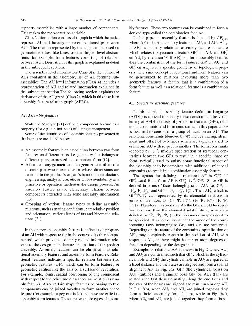
Examples of relational AFs is shown in Fig. 2 where AU1
and AU2 are constrained such that GF11, which is the cylind-
rical hole and GF12 the cylindrical hole in AU2 are spaced at
a ®xed distance and their axes are aligned and form a spatial
alignment AF. In Fig. 3(a) GF24 (the cylindrical boss) on
AU4 (turbine) and a similar boss GF15 on AU5 (fan) are
related such that they are mating along the end faces and
the axes of the bosses are aligned and result in a bridge AF.
In Fig. 3(b), when AU1 and AU2 are joined together they
form a `hole' assembly form feature, while in Fig. 3(c),
when AU6 and AU7 are joined together they form a `boss'
N. Shyamsundar, R. Gadh / Computer-Aided Design 33 (2001) 637±651640
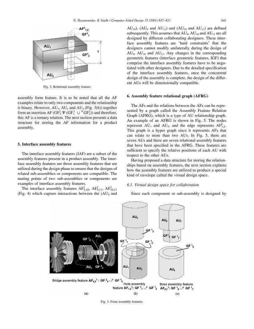
assembly form feature. It is to be noted that all the AF
examples relate to only two components and the relationship
is binary. However, AU3, AU1 and AU2 (Fig. 3(b)) together
form an insertion AF (GF13 C (GF 1
1 < # GF12)) and therefore,
this AF is a ternary relation. The next section presents a data
structure for storing the AF information for a product
assembly.
5. Interface assembly features
The interface assembly features (IAF) are a subset of the
assembly features present in a product assembly. The inter-
face assembly features are those assembly features that are
utilized during the design phase to ensure that the designs of
related sub-assemblies or components are compatible. The
mating points of two sub-assemblies or components are
examples of interface assembly features.
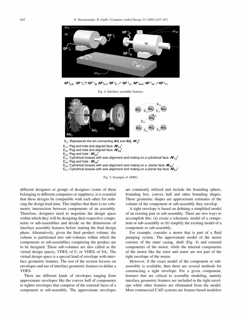
The interface assembly features AF19;10, AF1
9;11, AF110;11
(Fig. 4) which capture interactions between the (AU9 and
AU10), (AU9 and AU11) and (AU10 and AU11) are de®ned
subsequently. This assumes that AU9, AU10 and AU11 are all
designed by different collaborating designers. These inter-
face assembly features are `hard constraints' that the
designers cannot modify unilaterally during the design of
AU9, AU10 and AU11. Any changes in the corresponding
geometric features (interface geometric features, IGF) that
comprise the interface assembly features have to be nego-
tiated with other designers. Due to the detailed speci®cation
of the interface assembly features, once the concurrent
design of the assembly is complete, the design of the differ-
ent AUs will be dimensionally compatible.
6. Assembly feature relational graph (AFRG)
The AFs and the relations between the AFs can be repre-
sented by a graph called the Assembly Feature Relation
Graph (AFRG), which is a type of AU relationship graph.
An example of an AFRG is shown in Fig. 5. The nodes
represent AU1 and AU2, and the edge represents AFk1;2.
This graph is a hyper graph since it represents AFs that
can relate to more than two AUs. In Fig. 5, there are
seven AUs and there are seven relational assembly features
that have been speci®ed in the AFRG. These features are
suf®cient to specify the relative positions of each AU with
respect to the other AUs.
Having proposed a data structure for storing the relation-
ships based on assembly features, the next section explains
how the assembly features are utilized to produce a special
kind of envelope called the virtual design space.
6.1. Virtual design space for collaboration
Since each component or sub-assembly is designed by
N. Shyamsundar, R. Gadh / Computer-Aided Design 33 (2001) 637±651 641
Fig. 2. Relational assembly feature.
Fig. 3. Form assembly features.
different designers or groups of designers (some of them
belonging to different companies or suppliers), it is essential
that these designs be compatible with each other for redu-
cing the design lead-time. This implies that there is no volu-
metric intersection between components of an assembly.
Therefore, designers need to negotiate the design space
within which they will be designing their respective compo-
nents or sub-assemblies and decide on the dimensions of
interface assembly features before starting the ®nal design
phase. Alternatively, given the ®nal product volume, the
volume is partitioned into sub-volumes within which the
components or sub-assemblies comprising the product are
to be designed. These sub-volumes are also called as the
virtual design spaces, VDESi of Ci or VDESi of SAi. The
virtual design space is a special kind of envelope with inter-
face geometric features. The rest of the section focuses on
envelopes and use of interface geometric features to de®ne a
VDES.
There are different kinds of envelopes ranging from
approximate envelopes like the convex hull of components
to tighter envelopes that comprise of the external faces of a
component or sub-assembly. The approximate envelopes
are commonly utilized and include the bounding sphere,
bounding box, convex hull and other bounding shapes.
These geometric shapes are approximate estimates of the
volume of the component or sub-assembly they envelop.
A tight envelope is based on de®ning a simpli®ed model
of an existing part or sub-assembly. There are two ways to
accomplish this: (a) create a schematic model of a compo-
nent or sub-assembly or (b) simplify the existing model of a
component or sub-assembly.
For example, consider a motor that is part of a ¯uid
pumping system. The approximate model of the motor
consists of the outer casing, shaft (Fig. 4) and external
components of the motor, while the internal components
of the motor like the rotor and stator are not part of the
tight envelope of the motor.
However, if the exact model of the component or sub-
assembly is available, then there are several methods for
constructing a tight envelope. For a given component,
features that are critical to assembly modeling, namely
interface geometric features are included in the tight envel-
ope while other features are eliminated from the model.
Most commercial CAD systems are feature-based modelers
N. Shyamsundar, R. Gadh / Computer-Aided Design 33 (2001) 637±651642
Fig. 5. Example of AFRG.
Fig. 4. Interface assembly features.
and provide the functionality to delete speci®c shape
features from the model. Examples of some features that
are not critical for assembly modeling include chamfers
and ®llets that are not located on assembly features.
For a given sub-assembly, the exact CAD model of the
sub-assembly can be simpli®ed in two steps. In the ®rst step
components not required for assembly modeling at a parti-
cular level of abstraction (or a given interpretation) are
eliminated (for example internal components). This is a
special case of hierarchical simpli®cation that is applied to
a sub-assembly to obtain a simpli®ed model of the sub-
assembly. In the second step features that are not interface
geometric features are eliminated resulting in a simpli®ed
model of the component or sub-assembly.
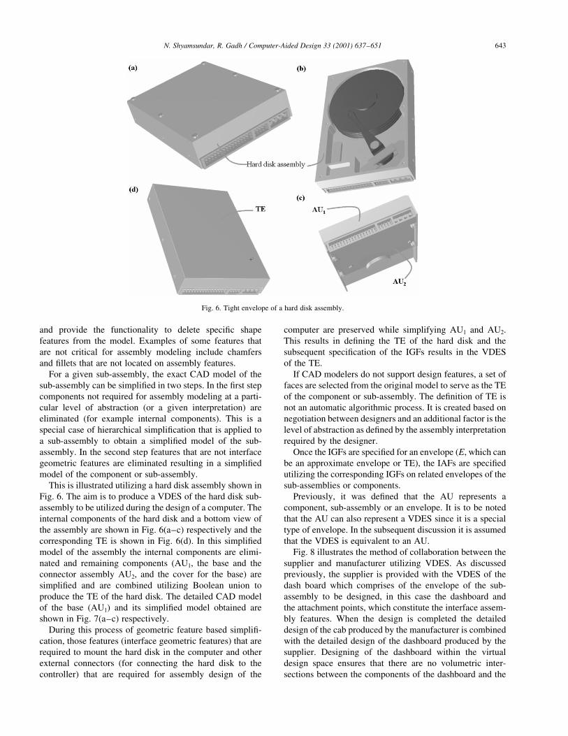
This is illustrated utilizing a hard disk assembly shown in
Fig. 6. The aim is to produce a VDES of the hard disk sub-
assembly to be utilized during the design of a computer. The
internal components of the hard disk and a bottom view of
the assembly are shown in Fig. 6(a±c) respectively and the
corresponding TE is shown in Fig. 6(d). In this simpli®ed
model of the assembly the internal components are elimi-
nated and remaining components (AU1, the base and the
connector assembly AU2, and the cover for the base) are
simpli®ed and are combined utilizing Boolean union to
produce the TE of the hard disk. The detailed CAD model
of the base (AU1) and its simpli®ed model obtained are
shown in Fig. 7(a±c) respectively.
During this process of geometric feature based simpli®-
cation, those features (interface geometric features) that are
required to mount the hard disk in the computer and other
external connectors (for connecting the hard disk to the
controller) that are required for assembly design of the
computer are preserved while simplifying AU1 and AU2.
This results in de®ning the TE of the hard disk and the
subsequent speci®cation of the IGFs results in the VDES
of the TE.
If CAD modelers do not support design features, a set of
faces are selected from the original model to serve as the TE
of the component or sub-assembly. The de®nition of TE is
not an automatic algorithmic process. It is created based on
negotiation between designers and an additional factor is the
level of abstraction as de®ned by the assembly interpretation
required by the designer.
Once the IGFs are speci®ed for an envelope (E, which can
be an approximate envelope or TE), the IAFs are speci®ed
utilizing the corresponding IGFs on related envelopes of the
sub-assemblies or components.
Previously, it was de®ned that the AU represents a
component, sub-assembly or an envelope. It is to be noted
that the AU can also represent a VDES since it is a special
type of envelope. In the subsequent discussion it is assumed
that the VDES is equivalent to an AU.
Fig. 8 illustrates the method of collaboration between the
supplier and manufacturer utilizing VDES. As discussed
previously, the supplier is provided with the VDES of the
dash board which comprises of the envelope of the sub-
assembly to be designed, in this case the dashboard and
the attachment points, which constitute the interface assem-
bly features. When the design is completed the detailed
design of the cab produced by the manufacturer is combined
with the detailed design of the dashboard produced by the
supplier. Designing of the dashboard within the virtual
design space ensures that there are no volumetric inter-
sections between the components of the dashboard and the
N. Shyamsundar, R. Gadh / Computer-Aided Design 33 (2001) 637±651 643
Fig. 6. Tight envelope of a hard disk assembly.
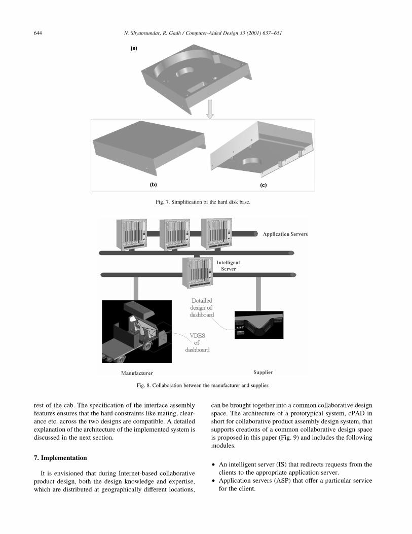
rest of the cab. The speci®cation of the interface assembly
features ensures that the hard constraints like mating, clear-
ance etc. across the two designs are compatible. A detailed
explanation of the architecture of the implemented system is
discussed in the next section.
7. Implementation
It is envisioned that during Internet-based collaborative
product design, both the design knowledge and expertise,
which are distributed at geographically different locations,
can be brought together into a common collaborative design
space. The architecture of a prototypical system, cPAD in
short for collaborative product assembly design system, that
supports creations of a common collaborative design space
is proposed in this paper (Fig. 9) and includes the following
modules.
² An intelligent server (IS) that redirects requests from the
clients to the appropriate application server.
² Application servers (ASP) that offer a particular service
for the client.
N. Shyamsundar, R. Gadh / Computer-Aided Design 33 (2001) 637±651644
Fig. 8. Collaboration between the manufacturer and supplier.
Fig. 7. Simpli®cation of the hard disk base.
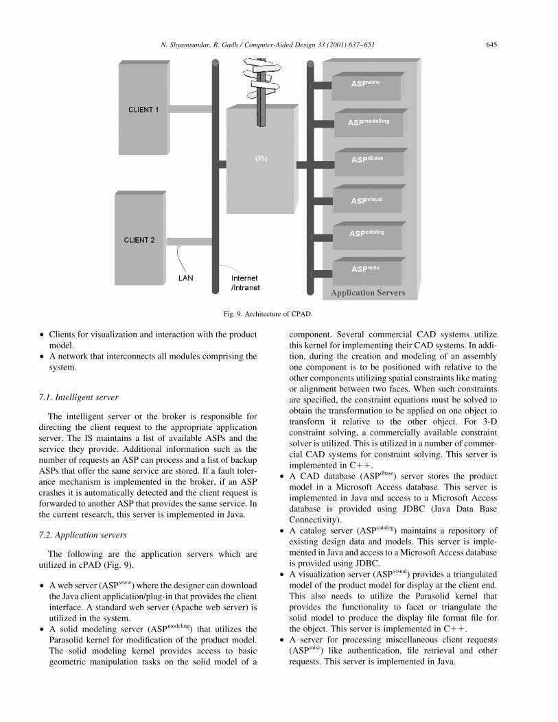
² Clients for visualization and interaction with the product
model.
² A network that interconnects all modules comprising the
system.
7.1. Intelligent server
The intelligent server or the broker is responsible for
directing the client request to the appropriate application
server. The IS maintains a list of available ASPs and the
service they provide. Additional information such as the
number of requests an ASP can process and a list of backup
ASPs that offer the same service are stored. If a fault toler-
ance mechanism is implemented in the broker, if an ASP
crashes it is automatically detected and the client request is
forwarded to another ASP that provides the same service. In
the current research, this server is implemented in Java.
7.2. Application servers
The following are the application servers which are
utilized in cPAD (Fig. 9).
² A web server (ASPwww) where the designer can download
the Java client application/plug-in that provides the client
interface. A standard web server (Apache web server) is
utilized in the system.
² A solid modeling server (ASPmodeling) that utilizes the
Parasolid kernel for modi®cation of the product model.
The solid modeling kernel provides access to basic
geometric manipulation tasks on the solid model of a
component. Several commercial CAD systems utilize
this kernel for implementing their CAD systems. In addi-
tion, during the creation and modeling of an assembly
one component is to be positioned with relative to the
other components utilizing spatial constraints like mating
or alignment between two faces. When such constraints
are speci®ed, the constraint equations must be solved to
obtain the transformation to be applied on one object to
transform it relative to the other object. For 3-D
constraint solving, a commercially available constraint
solver is utilized. This is utilized in a number of commer-
cial CAD systems for constraint solving. This server is
implemented in C11.
² A CAD database (ASPdbase) server stores the product
model in a Microsoft Access database. This server is
implemented in Java and access to a Microsoft Access
database is provided using JDBC (Java Data Base
Connectivity).
² A catalog server (ASPcatalog) maintains a repository of
existing design data and models. This server is imple-
mented in Java and access to a Microsoft Access database
is provided using JDBC.
² A visualization server (ASPvisual) provides a triangulated
model of the product model for display at the client end.
This also needs to utilize the Parasolid kernel that
provides the functionality to facet or triangulate the
solid model to produce the display ®le format ®le for
the object. This server is implemented in C11.
² A server for processing miscellaneous client requests
(ASPmisc) like authentication, ®le retrieval and other
requests. This server is implemented in Java.
N. Shyamsundar, R. Gadh / Computer-Aided Design 33 (2001) 637±651 645
Fig. 9. Architecture of CPAD.
7.3. Client interface
The client interface in the cPAD system was developed
using Java. The graphical user interface is based on Swing
and the 3-D visualization and interaction is accomplished
using Java3-D.The operations supported by the client are as
follows.
² File operations: Secure saving and retrieving of a product
model in personal as well as group database. Retrieving
models for viewing and editing. Uploading a CAD model
from the client to the server for modi®cation and storing
in the server database.
² Visualization operations supported are transformation,
scaling and zooming.
² Creation of basic primitives and envelopes, modi®cation
of the model utilizing Boolean operations, speci®cation
of geometric features and subsequently specifying the
assembly features utilizing these geometric features,
attaching annotations to the models, setting up a hierarch-
ical model (based on AHG) of the product that speci®es
the product in multiple levels of detail.
² Integration of the design with engineering catalogs which
provides the designer with an interface to browse cata-
logs and download the required models.
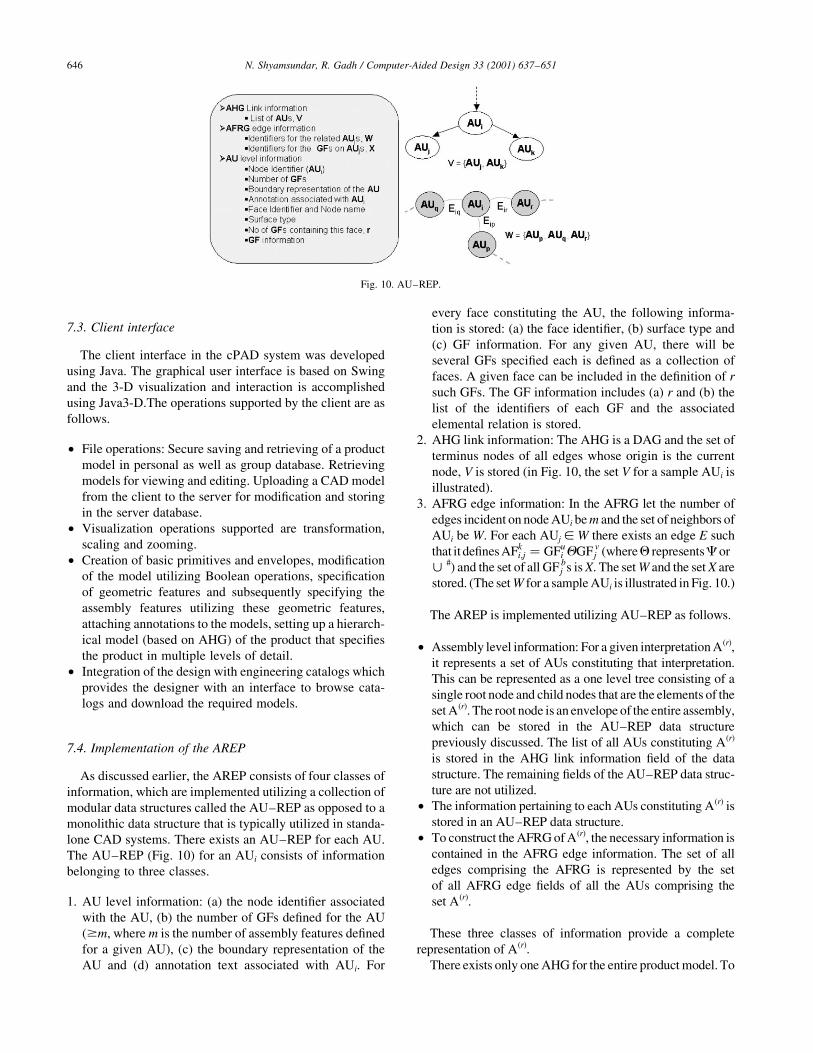
7.4. Implementation of the AREP
As discussed earlier, the AREP consists of four classes of
information, which are implemented utilizing a collection of
modular data structures called the AU±REP as opposed to a
monolithic data structure that is typically utilized in standa-
lone CAD systems. There exists an AU±REP for each AU.
The AU±REP (Fig. 10) for an AUi consists of information
belonging to three classes.
1. AU level information: (a) the node identi®er associated
with the AU, (b) the number of GFs de®ned for the AU
($m, where m is the number of assembly features de®ned
for a given AU), (c) the boundary representation of the
AU and (d) annotation text associated with AUi. For
every face constituting the AU, the following informa-
tion is stored: (a) the face identi®er, (b) surface type and
(c) GF information. For any given AU, there will be
several GFs speci®ed each is de®ned as a collection of
faces. A given face can be included in the de®nition of r
such GFs. The GF information includes (a) r and (b) the
list of the identi®ers of each GF and the associated
elemental relation is stored.
2. AHG link information: The AHG is a DAG and the set of
terminus nodes of all edges whose origin is the current
node, V is stored (in Fig. 10, the set V for a sample AUi is
illustrated).
3. AFRG edge information: In the AFRG let the number of
edges incident on node AUi be m and the set of neighbors of
AUi be W. For each AUj [ W there exists an edge E such
that it de®nes AFki;j � GFu
i QGF vj (whereQ representsCor
< #) and the set of all GF bj s is X. The set W and the set X are
stored. (The set W for a sample AUi is illustrated in Fig. 10.)
The AREP is implemented utilizing AU±REP as follows.
² Assembly level information: For a given interpretation A(r),
it represents a set of AUs constituting that interpretation.
This can be represented as a one level tree consisting of a
single root node and child nodes that are the elements of the
set A(r). The root node is an envelope of the entire assembly,
which can be stored in the AU±REP data structure
previously discussed. The list of all AUs constituting A(r)
is stored in the AHG link information ®eld of the data
structure. The remaining ®elds of the AU±REP data struc-
ture are not utilized.
² The information pertaining to each AUs constituting A(r) is
stored in an AU±REP data structure.
² To construct the AFRG of A(r), the necessary information is
contained in the AFRG edge information. The set of all
edges comprising the AFRG is represented by the set
of all AFRG edge ®elds of all the AUs comprising the
set A(r).
These three classes of information provide a complete
representation of A(r).
There exists only one AHG for the entire product model. To
N. Shyamsundar, R. Gadh / Computer-Aided Design 33 (2001) 637±651646
Fig. 10. AU±REP.
obtain the AHG that is a DAG, the AHG link information ®eld
of each AU is utilized. The set of all edges comprising the
AHG is represented by the set of all AHG link information
®eld of all the AUs comprising the sets A(1),¼A(k), and AE.
There are two versions of AREP for any given interpreta-
tion A(1) that are utilized in the cPAD.
1. The ®rst version of the representation is the primary
representation that is stored on the server. This consists
of the complete representation of A(r) as previously
discussed. The boundary model ®eld of the AU±REP
for each AU comprising A(r) consists of the KFF
(kernel/Parasolid ®le format) based representation of
the geometry of AU.
2. The other version is the secondary representation that is
utilized in the client. This is different from the primary
representation in that the boundary model ®eld of the
AU±REP for each AU comprising A(r) consists of the
compressed GFF (graphics/polygonized ®le format for
display) based representation of the geometry of AU.
It is the client side representation, the secondary repre-
sentation that is transmitted across the network to the client
and hence has to be compact.
As previously discussed, utilizing a GFF based represen-
tation to represent the geometry of AU is suitable only for
visualization. For modi®cation and other related tasks,
access to KFF based description of AU is required. Such a
representation is stored in the primary representation of AU.
Therefore, an augmented GFF is utilized in the secondary
representation. This mapping is at the AU level as well as at
the face level.
² AU level mapping: The node identi®er ®eld of the AU±
REP provides a mapping between the primary and
secondary representations of an AU.
² Face level mapping: The face identi®er ®eld of the AU±
REP provides a mapping between the faces of the
primary and secondary representations of an AU.
These mappings overcome the limitation of utilizing a
polygonized representation of assembly as a primary repre-
sentation and operations like modifying the geometry and
querying geometric information is possible utilizing the
representation proposed in this paper. Simple activities
like viewing of the model can be accomplished on the client
utilizing the augmented GFF while complex activities like
modi®cation of the geometry is accomplished on the server
utilizing the exact geometry stored in KFF. Further in this
research the polygonized mesh produced is compressed
utilizing a utility built into Java3-D further reducing the
size of the secondary representation.
For any given product assembly there exist k interpretations
A(1),¼A(k), in addition to AE. Let the set one of the k inter-
pretations available A(1),¼A(k). The universal set U consists of
all the AUs comprising the interpretations A(1),¼A(k), and AE.
The server maintains the primary representation version of the
AU±REP for each AUi [ U. This is primary product assem-
bly representation and is stored in the ASPdbase and constitutes
the complete AREP of the product assembly. At any given
time the client has the complete representation of one of the
interpretations of the assembly.
8. Results and discussion
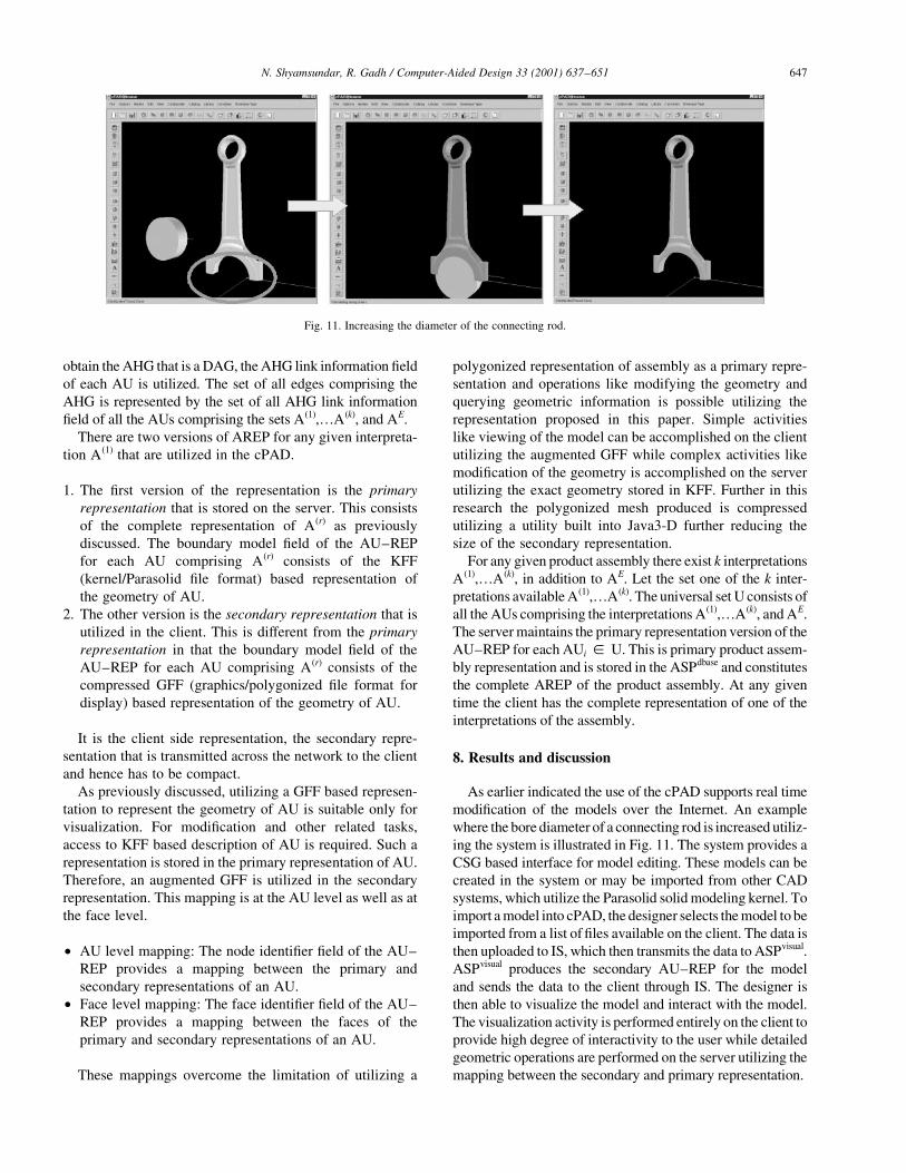
As earlier indicated the use of the cPAD supports real time
modi®cation of the models over the Internet. An example
where the bore diameter of a connecting rod is increased utiliz-
ing the system is illustrated in Fig. 11. The system provides a
CSG based interface for model editing. These models can be
created in the system or may be imported from other CAD
systems, which utilize the Parasolid solid modeling kernel. To
import a model into cPAD, the designer selects the model to be
imported from a list of ®les available on the client. The data is
then uploaded to IS, which then transmits the data to ASPvisual.
ASPvisual produces the secondary AU±REP for the model
and sends the data to the client through IS. The designer is
then able to visualize the model and interact with the model.
The visualization activity is performed entirely on the client to
provide high degree of interactivity to the user while detailed
geometric operations are performed on the server utilizing the
mapping between the secondary and primary representation.
N. Shyamsundar, R. Gadh / Computer-Aided Design 33 (2001) 637±651 647
Fig. 11. Increasing the diameter of the connecting rod.
The speci®cation of assembly features for connecting rod
assembly is illustrated in Fig. 12. Here the geometric
features GF11, and GF1
2 are speci®ed and the constraint
between the geometric features are speci®ed resulting in
de®nition of GF11;2. In this example, the face mapping
between the secondary and primary representation is
utilized providing the designer with the ability to highlight
the speci®c geometric features on AUs and specify
constraints. The constraint solving is performed on the
server utilizing the feature highlighted on the client and
the resulting transformations are returned to the client and
one of the AUs is repositioned with respect to the other.
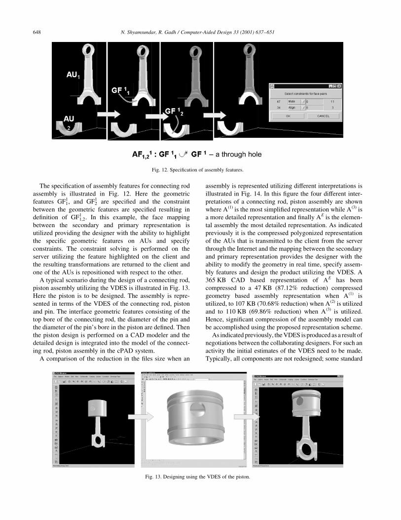
A typical scenario during the design of a connecting rod,
piston assembly utilizing the VDES is illustrated in Fig. 13.
Here the piston is to be designed. The assembly is repre-
sented in terms of the VDES of the connecting rod, piston
and pin. The interface geometric features consisting of the
top bore of the connecting rod, the diameter of the pin and
the diameter of the pin's bore in the piston are de®ned. Then
the piston design is performed on a CAD modeler and the
detailed design is integrated into the model of the connect-
ing rod, piston assembly in the cPAD system.
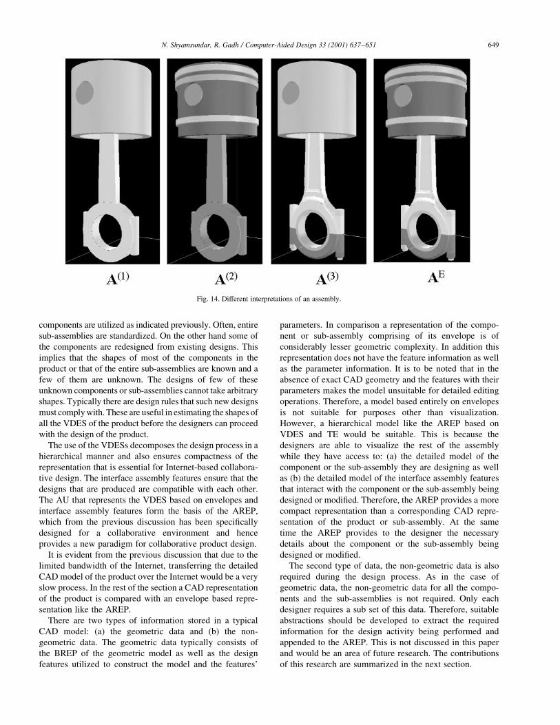
A comparison of the reduction in the ®les size when an
assembly is represented utilizing different interpretations is
illustrated in Fig. 14. In this ®gure the four different inter-
pretations of a connecting rod, piston assembly are shown
where A(1) is the most simpli®ed representation while A(3) is
a more detailed representation and ®nally AE is the elemen-
tal assembly the most detailed representation. As indicated
previously it is the compressed polygonized representation
of the AUs that is transmitted to the client from the server
through the Internet and the mapping between the secondary
and primary representation provides the designer with the
ability to modify the geometry in real time, specify assem-
bly features and design the product utilizing the VDES. A
365 KB CAD based representation of AE has been
compressed to a 47 KB (87.12% reduction) compressed
geometry based assembly representation when A(1) is
utilized, to 107 KB (70.68% reduction) when A(2) is utilized
and to 110 KB (69.86% reduction) when A(3) is utilized.
Hence, signi®cant compression of the assembly model can
be accomplished using the proposed representation scheme.
As indicated previously, the VDES is produced as a result of
negotiations between the collaborating designers. For such an
activity the initial estimates of the VDES need to be made.
Typically, all components are not redesigned; some standard
N. Shyamsundar, R. Gadh / Computer-Aided Design 33 (2001) 637±651648
Fig. 12. Speci®cation of assembly features.
Fig. 13. Designing using the VDES of the piston.
components are utilized as indicated previously. Often, entire
sub-assemblies are standardized. On the other hand some of
the components are redesigned from existing designs. This
implies that the shapes of most of the components in the
product or that of the entire sub-assemblies are known and a
few of them are unknown. The designs of few of these
unknown components or sub-assemblies cannot take arbitrary
shapes. Typically there are design rules that such new designs
must comply with. These are useful in estimating the shapes of
all the VDES of the product before the designers can proceed
with the design of the product.
The use of the VDESs decomposes the design process in a
hierarchical manner and also ensures compactness of the
representation that is essential for Internet-based collabora-
tive design. The interface assembly features ensure that the
designs that are produced are compatible with each other.
The AU that represents the VDES based on envelopes and
interface assembly features form the basis of the AREP,
which from the previous discussion has been speci®cally
designed for a collaborative environment and hence
provides a new paradigm for collaborative product design.
It is evident from the previous discussion that due to the
limited bandwidth of the Internet, transferring the detailed
CAD model of the product over the Internet would be a very
slow process. In the rest of the section a CAD representation
of the product is compared with an envelope based repre-
sentation like the AREP.
There are two types of information stored in a typical
CAD model: (a) the geometric data and (b) the non-
geometric data. The geometric data typically consists of
the BREP of the geometric model as well as the design
features utilized to construct the model and the features'
parameters. In comparison a representation of the compo-
nent or sub-assembly comprising of its envelope is of
considerably lesser geometric complexity. In addition this
representation does not have the feature information as well
as the parameter information. It is to be noted that in the
absence of exact CAD geometry and the features with their
parameters makes the model unsuitable for detailed editing
operations. Therefore, a model based entirely on envelopes
is not suitable for purposes other than visualization.
However, a hierarchical model like the AREP based on
VDES and TE would be suitable. This is because the
designers are able to visualize the rest of the assembly
while they have access to: (a) the detailed model of the
component or the sub-assembly they are designing as well
as (b) the detailed model of the interface assembly features
that interact with the component or the sub-assembly being
designed or modi®ed. Therefore, the AREP provides a more
compact representation than a corresponding CAD repre-
sentation of the product or sub-assembly. At the same
time the AREP provides to the designer the necessary
details about the component or the sub-assembly being
designed or modi®ed.
The second type of data, the non-geometric data is also
required during the design process. As in the case of
geometric data, the non-geometric data for all the compo-
nents and the sub-assemblies is not required. Only each
designer requires a sub set of this data. Therefore, suitable
abstractions should be developed to extract the required
information for the design activity being performed and
appended to the AREP. This is not discussed in this paper
and would be an area of future research. The contributions
of this research are summarized in the next section.
N. Shyamsundar, R. Gadh / Computer-Aided Design 33 (2001) 637±651 649
Fig. 14. Different interpretations of an assembly.
In summary the AREP has the following features.
² The AREP is a compact representation, as the assembly
model is compressed or simpli®ed in two stages: (a) at
component level and (b) at the feature level.
² The AREP provides an adaptive simpli®ed representation
scheme in which the details necessary for assembly
modeling are encapsulated in terms of assembly features.
² The AREP provides a uni®ed representation scheme for
storing multiple interpretations of the assembly model as
well as representing the assembly model both at the client
and the server end.
² The use of an assembly feature de®nition language
makes the assembly representations extensible. The
user can specify additional assembly features as required
by the application for which the representation is utilized.
In this research constraint propagation across multiple
interpretations of the assembly model is not currently imple-
mented. A mechanism to propagate assembly constraints
that are encapsulated in the form of assembly features
would be a useful addition to the system. The representation
currently does not store the number of degrees of freedom of
an assembly feature. If this information is available and the
directions of motion of one AU with respect to the other can
be captured by the representation and the analysis capabil-
ities can be added to the system. In the current research
assemblies consisting of nominal geometry was considered.
Additional work is needed to incorporate toleranced geome-
try into the AREP representation scheme.
9. Contributions
The AREP is based on the hierarchy of the top-down
design process and therefore provides a mechanism to
resolve speci®cation con¯icts early in the design stage and
enables concurrent design of the product. A new paradigm
for collaborative design based on the AREP is proposed.
The representation adaptively simpli®es the model of the
product thereby preserving the details (encapsulated in the
interface assembly features) of a particular component or
sub-assembly required during the product assembly design.
Therefore, it is a compact representation for transmitting the
product model over the Internet. In addition, the designers
are able to interact with a product model that provides the
required level of abstraction.
The cPAD system which implements the collaborative
paradigm provides a networked environment for product
assembly design that integrates collaboration, solid modeling
and features based design. The cPAD client functions as a
browser that interfaces with product design data and resources.
10. Summary
Due to the widespread use of computer aided design tools
as well as the Internet, the product design process is being
transformed into a collaborative activity wherein designers
share product models as well as related data to work
together despite geographically distant locations. The ®le
sizes of CAD based product models are typically very
large and their size constrains their use in a collaborative
Internet centric environment. Therefore, the data transfer
has to be minimized and a common approach to this
problem is utilizing a representation, which abstracts the
required information and transmit it across the Internet. In
this paper a representation scheme that can effectively
capture the necessary information was presented.
This representation of the assembly (called the AREP)
stores the assembly hierarchy as well as relations between
components and sub-assemblies with the use of a graph. The
nodes of the graph represent the components or sub-assem-
blies or virtual design spaces and the edges of the graph
represent the relation between components and sub-assem-
blies. These relations are de®ned in terms of assembly
features, which capture the interaction of geometric features
of the components/sub-assemblies. The assembly features
are themselves de®ned in terms of geometric features that
are available in a CAD model, or may have to be explicitly
extracted. The assembly features called interface assembly
features are used in conjunction with the virtual design
space, which is obtained after negotiations between the
collaborating designers to design the product. It is to be
noted that this representation is scaleable as well. The
assembly abstractions that constitute the AREP allow repre-
sentation of the product assembly in a compact manner for
Internet-based collaborative design involving companies
and subcontractors. The collaborative product assembly
design system based on this representation provides the
designers not only the capability to view but also modify,
specify assembly features and concurrently design assem-
blies thereby enabling designers (manufacturers and suppli-
ers) to collaborate effectively during assembly design.
Appendix A. List of de®nitions
AE Set of all components comprising the assembly
(elemental set)
AFDL Assembly feature de®nition language
AFRG Assembly feature relational graph
AHG Assembly hierarchy graph
ASP Application server
AFri;j;k The rth assembly feature of AUi and AUj
A(r) Set of all components comprising the rth inter-
pretation of an assembly
AREP Assembly representation
ASPdbase Database server
ASPmisc Server processing miscellaneous request
ASPmodeling Solid modeling server
ASPvisual Visualization server
ASPwww Web server
AUi ith Assembly unit
N. Shyamsundar, R. Gadh / Computer-Aided Design 33 (2001) 637±651650
AU±REP Representation of an AU
BREP Boundary representation
Ci The ith component
cPAD Collaborative product assembly design
DAG Directed acyclic graph
GFF Graphics ®le format
GFui The uth geometric feature of AUi
HR Relational representation
IAF Interface assembly feature
IGF Interface geometric feature
IS Intelligent server
K Total number of interpretations of an assembly
KFF Kernel ®le format
M Number of assembly features de®ned for a given
AU or number of edges incident on node represent-
ing a given AU
r Number of geometric features whose de®nition
include a given face of an AU
SAi The ith sub-assembly
TE Tight envelope
U The set of all AU comprising A(1),¼A(k), AE
V The set of terminus nodes of all edges whose origin
is the current node
VDES Virtual design space
W The set of neighbors of a node in the assembly
feature relational graph
C Relational constraint between geometric features
Ca Relational constraint between faces
< # Shape constraint
References
[1] Park M, Cutkosky MR. Framework for modeling dependencies in
collaborative engineering processes. Research in Engineering Design
1999;11:84±102.
[2] Rezayat M. The enterpriseÐweb portal for life-cycle support.
Computer-Aided Design 2000;32(2):85±96.
[3] Ullman DG. The mechanical design process. New York: McGraw-
Hill, 1997.
[4] Cutkosky MR, Tanenbaum JM, Glicksman J. Madefast: collaborative
engineering over the Internet. Communications of the ACM
1996;39(9):78±87.
[5] Cutkosky MR, Genesereth MR, Mark WS, Tenenbaum JM, Weber
JC. PACT: an experiment in integrating concurrent engineering
systems. Computer IEEE 1993;26(1):28±37.
[6] Regli WC. Internet-enabled computer aided design. Internet Comput-
ing IEEE 1997:39±50 Jan±Feb.
[7] Max®eld J, Fernando T, Dew P. Distributed virtual environment for
concurrent engineering, IEEE Annual Virtual Reality International
Symposium, Triangle Park, NC, USA, 1995. pp. 162±70.
[8] Roy U, Bharadwaj B, Kodkani SS, Cargain M. Product development
in a collaborative design environment. Concurrent Engineering
Research And Applications 1997;5(4):347±65.
[9] Floriani LD, Maulik A, Nagy G. Representation of solid objects by a
modulary boundary model. Computer-Aided Mechanical Assembly
Planning, 1991:41±80.
[10] Requicha AG, Whalen TW. Representations for assemblies. Compu-
ter-aided mechanical assembly planning. Boston: Kluwer Academic
Publishers, 1991.
[11] Cutkosky MR, Tenenbaum JM, Brown DR. Working with multiple
representations in a concurrent design system. Mechanical Design
Journal ASME Transactions 114:515±24.
[12] Shah JJ, Rogers MT. Assembly modeling as an extension of feature-
based design. Research in Engineering Design 1993;3(3&4):218±37.
[13] De Fazio TL, Edsall AC, Gustavson RE, Hernandez J, Hutchins PM,
Leung HW, Luby SC, Metzinger RW, Nevins JL, Tung K, Whitney
DE. A prototype of feature-based design for assembly. Mechanical
Design Journal ASME Transactions 115:723±34.
[14] Wedeking EL. Designing assemblies with solid models. Machine
Design 1987;59(2):67±71.
[15] Wilson RH, Latombe JC. Geometric reasoning about mechanical
assembly. Arti®cial Intelligence 1994;71(2):1±31.
[16] Mattikalli RS, Khosla PK. Motion constraints from contact geometry:
representation and analysis. IEEE International Conference on
Robotics and Automation, May, 1992. 2178±85.
[17] Woo TC, Dutta D. Automatic disassembly and total ordering in three
dimensions. Engineering for Industry Journal ASME Transactions
1991:207±13.
[18] Shyamsundar N, Ashai Z, Gadh R. Virtual design for disassembly
methodology. Engineering Design and Automation Journal
1998;4(1):13±26.
[19] Adler RM. Distributed co-ordination models for client/server comput-
ing. Computer IEEE 1995;28(4):14±22.
[20] Berger AW, Whitt W. Effective bandwidths with priorities. Trans-
actions on Networking IEEE/ACM 1998;6(4):447±60.
[21] Shah JJ, Mantyla M. Advances in feature based manufacturing.
Manufacturing research and technology. Amsterdam: Elsevier
Science, 1994.
N. Shyamsundar, R. Gadh / Computer-Aided Design 33 (2001) 637±651 651
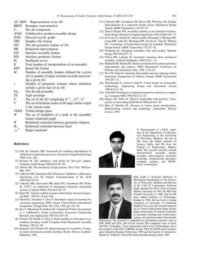
Rajit Gadh is Associate Professor ofMechanical Engineering at The Univer-sity of Wisconsin, Madison and Directorof the CAD±IT Consortium. ProfessorGadh obtained his Ph.D. From CarnegieMellon University in 1991, his MS fromCornell University in 1986, and his BSfrom Indian Institute of Technology,Kanpur in 1984. He has been a visitingresearcher at University of California,Berkeley for a year. His research interestsare in virtual reality-based shape design,shape abstractions for feature extractionin automatic meshing and virtual proto-typing, and geometry-based disassembly
abstractions. His research is supported by government agencies such asNSF, DOE and EPA, and several fortune 500 companies such as Ford,ALCOA, Caterpillar, Texas Instruments and Lucent Technologies. He isthe recipient of the NSF CAREER Award, 1995, the NSF/Lucent Technol-ogies Industrial Ecology Fellowship, 1997 and the Society of AutomotiveEngineers' Ralph R. Teetor Research and Educational award, 1993.
N. Shyamsundar is a Ph.D. candi-date in the Department of Mechan-ical Engineering at the Universityof Wisconsin, Madison. He has anMS from the Indian Institute ofScience, India, and BS from theCollege of Engineering, Madras,India. His research interests includeinternet-based assembly design,assembly representation, geometricmodeling, computational geometry,computer graphics and WWW-based technologies.


