
INFINITY REU-V2632FFUHD200I REU-V2632FFUC
Rinnai High Capacity Continuous Flow Gas Hot Water System
NOTE: This manual does not apply to models: REU-V1620WG, REU-V1620WB, REU-V2024WG, REU-V2024WE, REU-V2426WB, REU-V2626WG, REU-VM2630WD, REU-VM2630WC, REU-V2632FFUG, REU-VM2632FFUC
SERVICE MANUAL

All Rinnai products are certified by the Australian Gas Association as compliantto relevant Australian Standards.
Rinnai Australia Head Office is certifiedas complying with ISO 9001 by SAIGlobal.
Rinnai New Zealand has been certified toISO 9001 Quality Assurance by Telarc.
All Rinnai products are Certified toWaterMark by SAI Global. WaterMarkcertification is awarded to products andfittings complying with safety and watercontamination standards.
SAI Global

© Copyright Rinnai Australia Pty Ltd ABN 74 005 138 769 ACN 005 138 769 All rights reserved
Produced by Technical Services Department
August 2003 - Issue 1.
No portion or part of this manual may be copied without prior permission from Rinnai Australia.Rinnai Australia takes no responsibility for the accuracy or otherwise of information contained in
this manual, and reserves the right to make modifications and change specifications without notice.
Failure to comply with these instructions may result in serious personal injury or damage to the appliance.
This manual has been published by Rinnai Australia Technical Services. While many individualshave contributed to this publication, it will be successful only if you - the reader and customer -find it useful. We would like to extend an invitation to users of this manual to make contact withus, as your feedback and suggestions are valuable resources for us to include as improvements.Rinnai are constantly working toward supply improved appliances as well as information, andspecifications may be subject to alteration at any time.
SM REU-V2632FFU/FFUCIssue No1
WARNING
ALL WIRING INSIDE THIS APPLIANCE MAY BE AT 240 VOLTS POTENTIAL
ALL SERVICE WORK MUST BE CARRIED OUT BY AN AUTHORISED PERSON.
DO NOT TEST FOR GAS ESCAPES WITH AN OPEN FLAME


Infinity REU-V2632FFU / HD200I REU-V2632FFUC - v - Issue 1 - 10/02/04 ©Rinnai
Table of Contents Glossary of Terms and Symbols ................................................................................ vi
1. Introduction ................................................................................................................ 1
2. Specifications ............................................................................................................. 2
3. Water Flow Rates and Pressures ................................................................................ 4
4. Dimensions ................................................................................................................ 8
5. Remote Controls ........................................................................................................ 9
6. Cutaway Diagram .................................................................................................... 13
7. Operational Flow Chart ........................................................................................... 14
8. Operation Principles ................................................................................................ 16
9. Main Components .................................................................................................... 17
10. Time Charts ............................................................................................................ 19
11. Wiring Diagram ..................................................................................................... 20
12. Dip Switch Settings ............................................................................................... 21
13. Fault Finding .......................................................................................................... 22
14. Component Circuit Value Table ............................................................................ 24
15. Component and Circuit Checks ............................................................................. 25
16. Maintenance Monitor / Error History .................................................................... 32
17. Gas Pressure Setting Procedure ............................................................................. 34
18. Gas Conversion Procedure ..................................................................................... 36
19. Dismantling for Service ......................................................................................... 42
20. Exploded Diagram ................................................................................................. 51
21. Parts List ................................................................................................................ 55
SERVICE CONTACT POINTS ............................................................................... 59
Infinity REU-V2632FFU / HD200I REU-V2632FFUC - vi - Issue 1 - 10/02/04 ©Rinnai
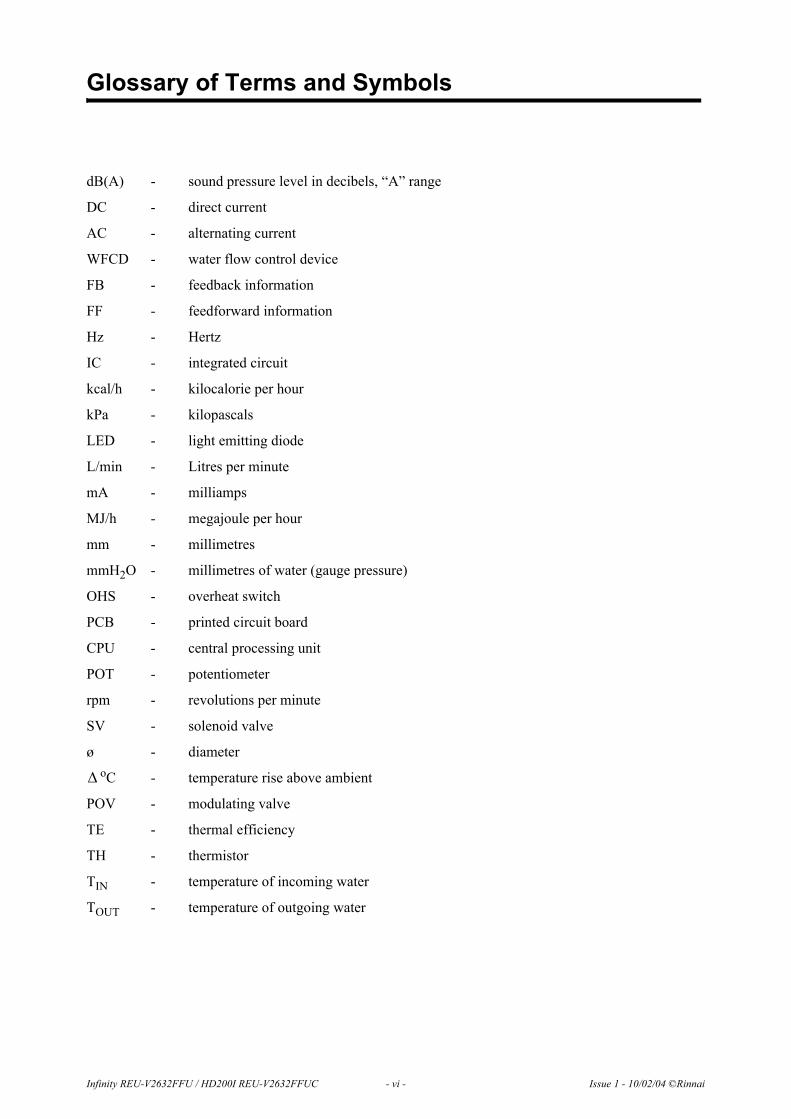
Glossary of Terms and Symbols
dB(A) - sound pressure level in decibels, “A” range
DC - direct current
AC - alternating current
WFCD - water flow control device
FB - feedback information
FF - feedforward information
Hz - Hertz
IC - integrated circuit
kcal/h - kilocalorie per hour
kPa - kilopascals
LED - light emitting diode
L/min - Litres per minute
mA - milliamps
MJ/h - megajoule per hour
mm - millimetres
mmH2O - millimetres of water (gauge pressure)
OHS - overheat switch
PCB - printed circuit board
CPU - central processing unit
POT - potentiometer
rpm - revolutions per minute
SV - solenoid valve
ø - diameteroC - temperature rise above ambient
POV - modulating valve
TE - thermal efficiency
TH - thermistor
TIN - temperature of incoming water
TOUT - temperature of outgoing water
∆
Infinity REU-V2632FFU / HD200I REU-V2632FFUC - 1 - Issue 1 - 10/02/04 ©Rinnai
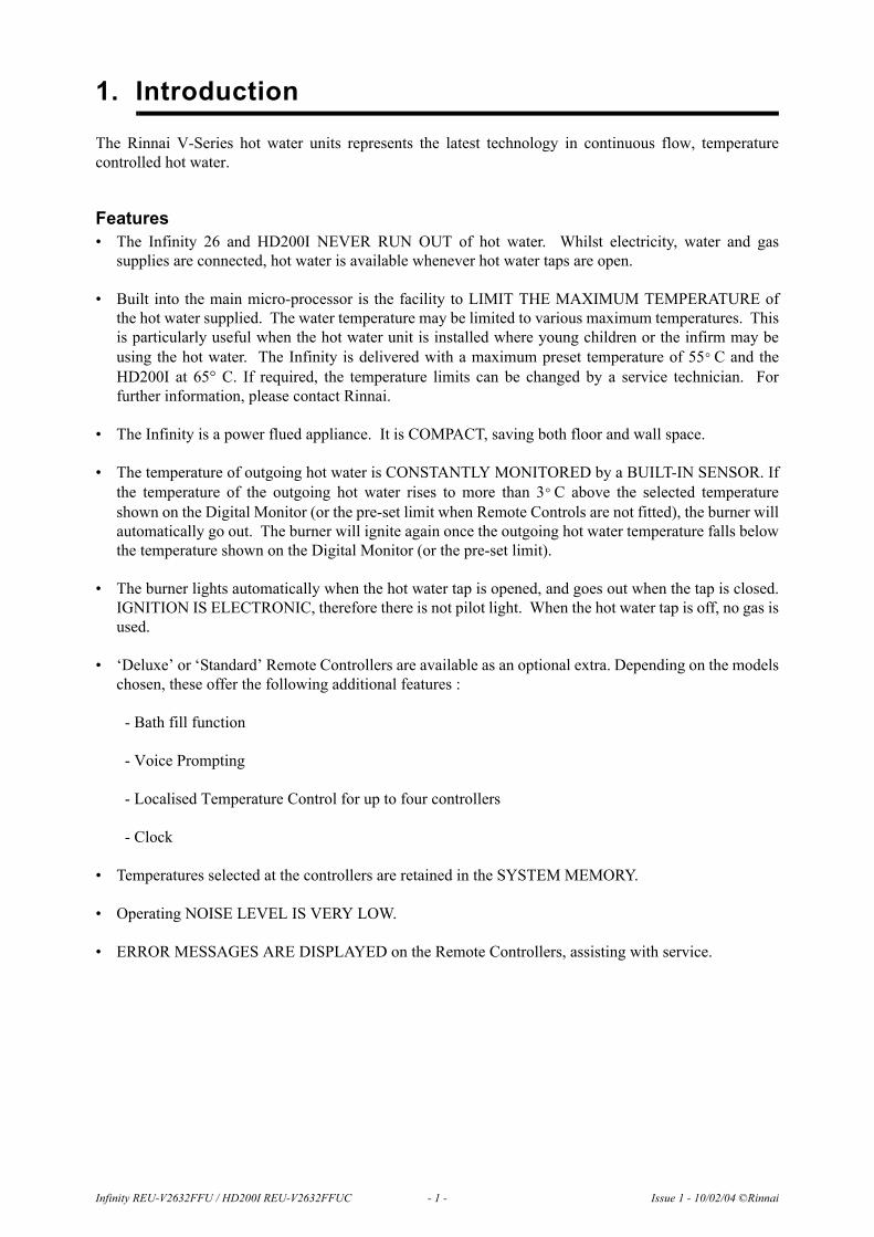
1. Introduction
The Rinnai V-Series hot water units represents the latest technology in continuous flow, temperaturecontrolled hot water.
Features• The Infinity 26 and HD200I NEVER RUN OUT of hot water. Whilst electricity, water and gas
supplies are connected, hot water is available whenever hot water taps are open.
• Built into the main micro-processor is the facility to LIMIT THE MAXIMUM TEMPERATURE ofthe hot water supplied. The water temperature may be limited to various maximum temperatures. Thisis particularly useful when the hot water unit is installed where young children or the infirm may beusing the hot water. The Infinity is delivered with a maximum preset temperature of 55 C and theHD200I at 65° C. If required, the temperature limits can be changed by a service technician. Forfurther information, please contact Rinnai.
• The Infinity is a power flued appliance. It is COMPACT, saving both floor and wall space.
• The temperature of outgoing hot water is CONSTANTLY MONITORED by a BUILT-IN SENSOR. Ifthe temperature of the outgoing hot water rises to more than 3 C above the selected temperatureshown on the Digital Monitor (or the pre-set limit when Remote Controls are not fitted), the burner willautomatically go out. The burner will ignite again once the outgoing hot water temperature falls belowthe temperature shown on the Digital Monitor (or the pre-set limit).
• The burner lights automatically when the hot water tap is opened, and goes out when the tap is closed.IGNITION IS ELECTRONIC, therefore there is not pilot light. When the hot water tap is off, no gas isused.
• ‘Deluxe’ or ‘Standard’ Remote Controllers are available as an optional extra. Depending on the modelschosen, these offer the following additional features :
- Bath fill function
- Voice Prompting
- Localised Temperature Control for up to four controllers
- Clock
• Temperatures selected at the controllers are retained in the SYSTEM MEMORY.
• Operating NOISE LEVEL IS VERY LOW.
• ERROR MESSAGES ARE DISPLAYED on the Remote Controllers, assisting with service.
°
°

2. Specifications
Note 1: The default factory setting is 55ºC for REU-V2632FFU. 65°C for REU-V2632FFUC. The unit can be ordered from Rinnai to be pre-set to any of the other temperatures listed. The unit can be pre-set to any of the temperatures listed by a suitably qualified person.Controllers are available with default temperatures up to 75º C. When fitted with controllers, only temperatures not exceeding the default temperatures can be selected. When fitted without controllers, the unit will deliver water at the default temperature. Controllers are not available with 85° C settings.
Note 2: Unit will operate at lower pressures but the maximum rated flow of 32L/min. will not be achieved.
Model No. REU - V2632FFU / REU - V2632FFUCType of Appliance Temp.controlled continuous Flow Gas Hot Water UnitOperation With/without remote controls, mounted in Kitchen, bathroom, etc.Exhaust System Direct Vent - Forced FlueInstallation Internally mounted (Indoor Only)Available Default Temperatures (Note 1):(without Remote Controllers)
40º C, 43º C, 50º C, 55º C, 60º C, 65º C, 75º C, 85º C (set by combination of Dip switches on PCB)
Temperature Range (with Remote Controllers) Kitchen controller : 37 ~ 55º CBathroom controller : 37 ~ 50º C
Dimensions (mm)Width 350
Height 600Depth 224
Weight (Kg) 22
ConnectionsGas 20A (R3/4)
Cold Water Supply 20A (R3/4)Hot Water Supply 20A (R3/4)
Ignition System Direct Electronic IgnitionGas Consumption (Max. / Min)
Natural Gas 195 ~ 16 MJ/hPropane Gas 195 ~ 16 MJ/h
Output (Max./ Min.).(kW) REU-V2632FFU / REU-V2632FFUC: 46.9 / 3.8Hot Water Delivery Capacity 26 to 32 L/min.Noise level 49 dB(A)Thermal Efficiency 87%NOXaf 55 ppm Max.Minimum Operating Water Flow (Note 2): 2.4 L/min.Minimum Operating Pressure (Note 2): 180 kPaMaximum Operating Water flow 32 L/min.Nominal Operat-ing Pressure
Less than 60°C 140 kPaGreater than or equal to 60°C 200 ~ 1000 kPa
Power Supply Infinity Unit AC 240 Volts (50 Hz)Remote Control (optional) DC 12 Volts (Digital)
Water temperature control Simulation feedforward and feedbackWater flow control
Electronic Water flow sensor flow control & heat exchanger by-pass flow control.
Safety Device
Flame Failure Flame rodBoil dry Water flow sensor
Remaining Flame (OHS) 97º C bi-metal switchOver temperature 95º C lockout thermistor
Fusible link 129º C Thermal FusePressure relief valve Opens 2060 kPa, closes 1470 kPa
Combustion fan rpm check Integrated circuit systemOver current Glass fuse (3 Amp).
RemoteControllers(optional)
Kitchen MC91-1A or MC-70-2A or (MC-33-3A)Bathroom MC91-1A or BC-70-2A or (BC-45-3A)
Second Bathroom MC91-1A or BC-70-2A or (BSC-45-3A)Third Bathroom MC91-1A
Remote Controller Cable (Optional) Two core sheathed (double insulated) flex with min.cross-sectional area of 0.5 mm²
Electrical Consumption
Normal 80WStandby 7.5 W (with 1 Remote Control)
Manifold Electronic Control System (Optional) MSA-2M, MSA-2S
Infinity REU-V2632FFU / HD200I REU-V2632FFUC - 2 - Issue 1 - 4/05/04 ©Rinnai
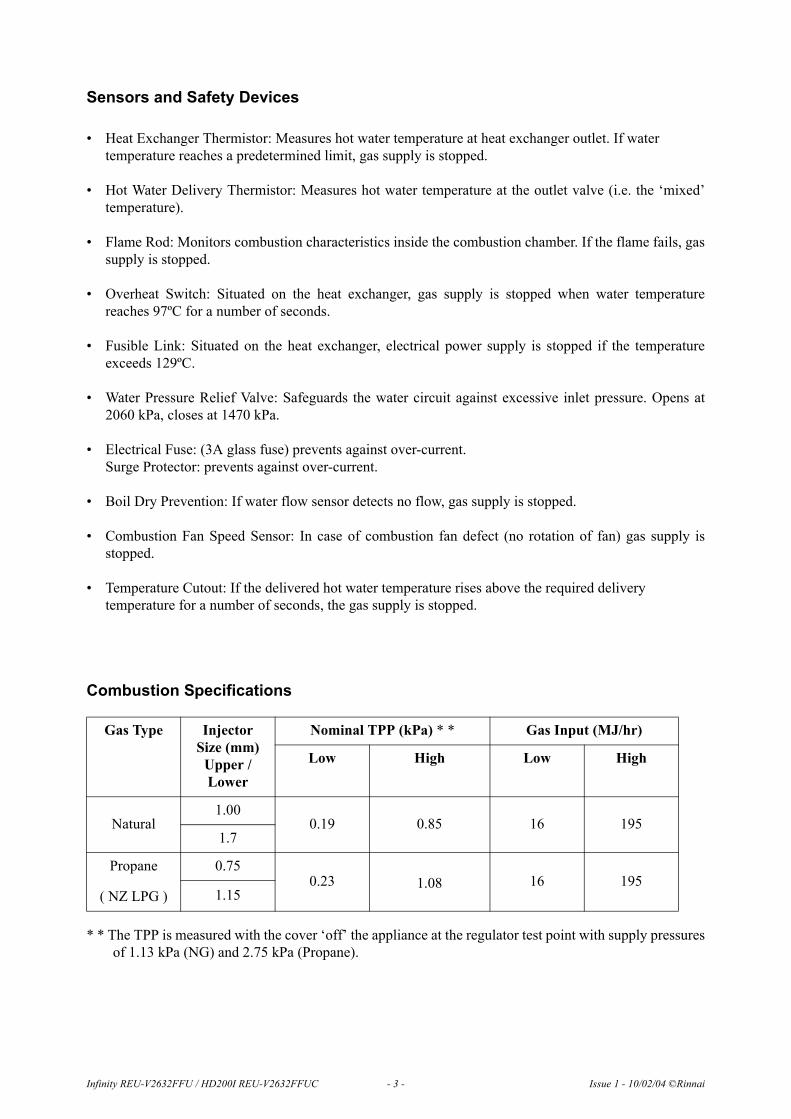
Sensors and Safety Devices
• Heat Exchanger Thermistor: Measures hot water temperature at heat exchanger outlet. If water temperature reaches a predetermined limit, gas supply is stopped.
• Hot Water Delivery Thermistor: Measures hot water temperature at the outlet valve (i.e. the ‘mixed’temperature).
• Flame Rod: Monitors combustion characteristics inside the combustion chamber. If the flame fails, gassupply is stopped.
• Overheat Switch: Situated on the heat exchanger, gas supply is stopped when water temperaturereaches 97ºC for a number of seconds.
• Fusible Link: Situated on the heat exchanger, electrical power supply is stopped if the temperatureexceeds 129ºC.
• Water Pressure Relief Valve: Safeguards the water circuit against excessive inlet pressure. Opens at2060 kPa, closes at 1470 kPa.
• Electrical Fuse: (3A glass fuse) prevents against over-current. Surge Protector: prevents against over-current.
• Boil Dry Prevention: If water flow sensor detects no flow, gas supply is stopped.
• Combustion Fan Speed Sensor: In case of combustion fan defect (no rotation of fan) gas supply isstopped.
• Temperature Cutout: If the delivered hot water temperature rises above the required delivery temperature for a number of seconds, the gas supply is stopped.
Combustion Specifications
* * The TPP is measured with the cover ‘off’ the appliance at the regulator test point with supply pressuresof 1.13 kPa (NG) and 2.75 kPa (Propane).
Gas Type Injector Size (mm)
Upper / Lower
Nominal TPP (kPa) * * Gas Input (MJ/hr)
Low High Low High
Natural1.00
0.19 0.85 16 1951.7
Propane
( NZ LPG )
0.750.23 1.08 16 195
1.15
Infinity REU-V2632FFU / HD200I REU-V2632FFUC - 3 - Issue 1 - 10/02/04 ©Rinnai

3. Water Flow Rates and Pressures
Water FlowsTable 1 shows unmixed and mixed water flow rates and approximate gas consumptions for varioustemperature rises. The unmixed flow rates are the flow rates available at the given temperature rise directlyat the outlet of the water heater. The mixed water flow rates are available at the given temperature rise bymixing hot water from the outlet of the water heater with cold water from the mains supply.
Water Flows can also be calculated by the following formula:
M = 60 x ( Q / C x T )
Where M = Water flow rate in litres/minute. If M is ≤ to 26, the water is unmixed. If M is > 26, the wateris mixed.Q = Heat energy available in kW = 47kW for the REU-V2632FFU / FFUCC = Specific heat of water = 4.2KJ/Kg C. C does not change for the purpose of this calculation.
T = Temperature rise required ( C)
Example:What is the flow rate available with an incoming water temperature of 10 C and a required temperature of20 C?
T = 20 - 10 = 10 CQ = 47C = 4.2M = 60 x ( 47 / (4.2 x 10) ) = 67 l/min. Since 67 is greater than 26 this flow rate is mixed. This resultcorresponds with the value in Table 1.
Table 1: Approximate Water Flows & Gas Usage - Rinnai Infinity REU-V2632FFU/FFUC - Preset Table
∆
°∆ °
°°
∆ °
Infinity REU-V2632FFU / HD200I REU-V2632FFUC - 4 - Issue 1 - 10/02/04 ©Rinnai
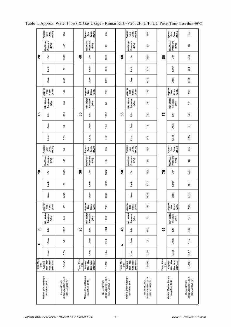
Table 1. Approx. Water Flows & Gas Usage - Rinnai REU-V2632FFU/FFUC Preset Temp. Less than 60°C.
TempRise
(ºC)
Approx.
Min/Max
GasInput
(MJ/hour)
L/sec
L/min
L/hr
MinWater
Pressure
(kPa)
Approx
Gas
Cons.
(MJ/h)
L/sec
L/min
L/hr
MinWater
Pressure
(kPa)
Approx
Gas
Cons.
(MJ/h)
L/sec
L/min
L/hr
MinWater
Pressure
(kPa)
Approx
Gas
Cons.
(MJ/h)
L/sec
L/min
L/hr
MinWater
Pressure
(kPa)
Approx
Gas
Cons.
(MJ/h)
RinnaiHD200I
(REU-V2632FFU-C)&
REU-V2632FFU
16-195
0.53
32
1920
140
47
0.53
32
1920
140
94
0.53
32
1920
140
141
0.53
32
1920
140
188
TempRise
(ºC)
Approx.
Min/Max
GasInput
(MJ/hour)
L/sec
L/min
L/hr
MinWater
Pressure
(kPa)
Approx
Gas
Cons.
(MJ/h)
L/sec
L/min
L/hr
MinWater
Pressure
(kPa)
Approx
Gas
Cons.
(MJ/h)
L/sec
L/min
L/hr
MinWater
Pressure
(kPa)
Approx
Gas
Cons.
(MJ/h)
L/sec
L/min
L/hr
MinWater
Pressure
(kPa)
Approx
Gas
Cons.
(MJ/h)
RinnaiHD200I
(REU-V2632FFU-C)&
REU-V2632FFU
16-195
0.44
26.4
1584
100
195
0.37
22.2
1332
65
195
0.32
19.2
1152
50
195
0.28
16.8
1008
40
195
TempRise
(ºC)
Approx.
Min/Max
GasInput
(MJ/hour)
L/sec
L/min
L/hr
MinWater
Pressure
(kPa)
Approx
Gas
Cons.
(MJ/h)
L/sec
L/min
L/hr
MinWater
Pressure
(kPa)
Approx
Gas
Cons.
(MJ/h)
L/sec
L/min
L/hr
MinWater
Pressure
(kPa)
Approx
Gas
Cons.
(MJ/h)
L/sec
L/min
L/hr
MinWater
Pressure
(kPa)
Approx
Gas
Cons.
(MJ/h)
RinnaiHD200I
(REU-V2632FFU-C)&
REU-V2632FFU
16-195
0.25
15
900
30
195
0.22
13.2
792
25
195
0.2
12
720
23
195
0.19
11.4
684
20
195
TempRise
(ºC)
Approx.
Min/Max
GasInput
(MJ/hour)
L/sec
L/min
L/hr
MinWater
Pressure
(kPa)
Approx
Gas
Cons.
(MJ/h)
L/sec
L/min
L/hr
MinWater
Pressure
(kPa)
Approx
Gas
Cons.
(MJ/h)
L/sec
L/min
L/hr
MinWater
Pressure
(kPa)
Approx
Gas
Cons.
(MJ/h)
L/sec
L/min
L/hr
MinWater
Pressure
(kPa)
Approx
Gas
Cons.
(MJ/h)
RinnaiHD200I
(REU-V2632FFU-C)&
REU-V2632FFU
16-195
0.17
10.2
612
19
195
0.16
9.6
576
18
195
0.15
9540
17
195
0.14
8.4
504
16
195
Models(Presettemps
lessthan60C)
20
30
35
40
10
15
50
55
60
65
70
75
80
Models(Presettemps
lessthan60C)
25
Models(Presettemps
lessthan60C)
455
Models(Presettemps
lessthan60C)
Infinity REU-V2632FFU / HD200I REU-V2632FFUC - 5 - Issue 1 - 10/02/04 ©Rinnai

Approx.Water Flows & Gas Usage -Rinnai REU-V2632FFU/FFUC Preset Temp.Greater than or equal to 60°C
TempRise
(ºC)
Approx.
Min/Max
GasInput
(MJ/hour)
L/sec
L/min
L/hr
MinWater
Pressure
(kPa)
Approx
Gas
Cons.
(MJ/h)
L/sec
L/min
L/hr
MinWater
Pressure
(kPa)
Approx
Gas
Cons.
(MJ/h)
L/sec
L/min
L/hr
MinWater
Pressure
(kPa)
Approx
Gas
Cons.
(MJ/h)
L/sec
L/min
L/hr
MinWater
Pressure
(kPa)
Approx
Gas
Cons.
(MJ/h)
RinnaiHD200I
(REU-V2632FFU-C)&
REU-V2632FFU
16-195
0.4
24
1440
200
36
0.4
24
1440
200
72
0.4
24
1440
200
108
0.4
24
1440
200
144
TempRise
(ºC)
L/sec
L/min
L/hr
MinWater
Pressure
(kPa)
Approx
Gas
Cons.
(MJ/h)
L/sec
L/min
L/hr
MinWater
Pressure
(kPa)
Approx
Gas
Cons.
(MJ/h)
L/sec
L/min
L/hr
MinWater
Pressure
(kPa)
Approx
Gas
Cons.
(MJ/h)
L/sec
L/min
L/hr
MinWater
Pressure
(kPa)
Approx
Gas
Cons.
(MJ/h)
Approx.
Min/Max
GasInput
(MJ/hour)
RinnaiHD200I
(REU-V2632FFU-C)&
REU-V2632FFU
16-195
0.4
24
1440
200
180
0.37
22.2
1332
112.5
199
0.32
19.2
1152
75
199
0.28
16.8
1008
60
199
TempRise
(ºC)
Approx.
Min/Max
GasInput
(MJ/hour)
L/sec
L/min
L/hr
MinWater
Pressure
(kPa)
Approx
Gas
Cons.
(MJ/h)
L/sec
L/min
L/hr
MinWater
Pressure
(kPa)
Approx
Gas
Cons.
(MJ/h)
L/sec
L/min
L/hr
MinWater
Pressure
(kPa)
Approx
Gas
Cons.
(MJ/h)
L/sec
L/min
L/hr
MinWater
Pressure
(kPa)
Approx
Gas
Cons.
(MJ/h)
RinnaiHD200I
(REU-V2632FFU-C)&
REU-V2632FFU
16-195
0.25
15
900
45
195
0.22
13.2
792
40
195
0.2
12
720
36
195
0.19
11.4
684
33
195
TempRise
(ºC)
Approx.
Min/Max
GasInput
(MJ/hour)
L/sec
L/min
L/hr
MinWater
Pressure
(kPa)
Approx
Gas
Cons.
(MJ/h)
L/sec
L/min
L/hr
MinWater
Pressure
(kPa)
Approx
Gas
Cons.
(MJ/h)
L/sec
L/min
L/hr
MinWater
Pressure
(kPa)
Approx
Gas
Cons.
(MJ/h)
L/sec
L/min
L/hr
MinWater
Pressure
(kPa)
Approx
Gas
Cons.
(MJ/h)
RinnaiHD200I
(REU-V2632FFU-C)&
REU-V2632FFU
16-195
0.17
10.2
612
31
195
0.16
9.6
576
29
195
0.15
9540
27
195
0.14
8.4
504
25
195
Models(Presettempsgreater
thanorequalto
60C)
10
15
20
255
50
55
60
65
70
75
80
30
35
Models(Presettempsgreater
thanorequalto
60C)
40
Models(Presettempsgreater
thanorequalto
60C)
45
Models(Presettempsgreater
thanorequalto
60C)
Infinity REU-V2632FFU / HD200I REU-V2632FFUC - 6 - Issue 1 - 10/02/04 ©Rinnai

Water PressureThe water pressure vs flow charcteristics is as follows:
WATER PRESSURE/FLOW RATE
0
5
10
15
20
25
30
35
WATER PRESSURE(kPa)
WA
TE
R F
LO
W R
AT
E (
L/m
in)
REU-V2632W/WC/FFU/FFUC 37 -55
REU-V2632W/WC/FFU/FFUC:60
& Higher
REU-V2626W
Infinity REU-V2632FFU / HD200I REU-V2632FFUC - 7 - Issue 1 - 10/02/04 ©Rinnai

Infinity REU-V2632FFU / HD200I REU-V2632FFUC - 8 - Issue 1 - 10/02/04 ©Rinnai
4. Dimensions

120
90
20
MC-91-1A
195
97
22
BC-70-2A
5. Remote Controls
Remote ControlsRemote Controllers are an optional extra. 'Standard' and 'Deluxe' controllers can befitted.Standard controllers allow temperature selection only. Deluxe controllers havetemperature selection, bath-fill and voice prompting functions. For detailedinformation regarding controller operation refer to the 'How to use your waterheater' booklet supplied with the appliance. Other manufacturers' controllers areNOT compatible with this appliance.
Standard Controller (Model MC-91)Up to 4 Standard Controllers can be fitted to the appliance. They are normallyinstalled in the areas where the majority of hot water is used, for example, thekitchen, bathroom, ensuite and laundry.
Deluxe Kitchen Remote Control (MC-70) and (BC-70A)Deluxe controllers have 'Kitchen' (MC-70-2A) and 'Bathroom' (BC-70-2A) versions. 'Kitchen' controls areintended for the Kitchen or other convenient area where the majority of hot water is used. BathroomControllers are intended to be fitted in the bathroom or ensuite and allow the user to have a bath filled tothe required level and temperature automatically.
:
Positioning of ControllersControllers must be installed in shaded and clean locations. They should be fitted out of reach of children(suggested height from floor at least 1500mm). Controllers are water resistant, however, durability isimproved when positioned outside the shower recess or at least 400mm above the highest part of a sink,basin or bath.
Up to three ‘Deluxe’ Controllers can be connected
If a fourth Controller is required a ‘Standard’ Controller can be included
Kitchen Bathroom Ensuite Kitchen Bathroom Ensuite LaundryMC70-2A MC70-2AMC70-2A MC70-2AMC70-2A BC70-2A MC70-2A BC70-2AMC70-2A BC70-2A BC70-2A MC70-2A BC70-2A BC70-2A MC91-1A
Infinity REU-V2632FFU / HD200I REU-V2632FFUC - 9 - Issue 1 - 10/02/04 ©Rinnai

DO NOT INSTALL THE CONTROLLERS• NEAR A HEAT SOURCE, SUCH AS A COOK TOP, STOVE OR OVEN. HEAT, STEAM,
SMOKE AND HOT OIL MAY CAUSE DAMAGE
• IN DIRECT SUNLIGHT
• OUTDOORS UNLESS AN ENCLOSURE IS PROVIDED WHICH PROTECTS THE CONTROLLER AGAINST SUNLIGHT AND DUST INGRESS.
• AGAINST A METAL WALL UNLESS THE WALL IS EARTHED IN ACCORDANCE
WITH AS/NZ3000.
Remote Controller ConnectionRemote controls operate at extra low voltage (12 Volts DC) which is supplied from the appliance.Controllers are supplied with 15 m of electrical cable. The cable wires for connection to the appliance arefitted with spade terminals.
Extension cables are available from Rinnai. Alternatively, a two core sheathed (double insulated) flex withminimum cross-sectional area of 0.5 mm² can be used. Maximum cable length is 50 m.
For connection refer to the “CONNECTING REMOTE CONTROL CABLES” section.
If the front cover of the appliance contains the following text install it in accordance with Diagram 1 below:
Water Heater and Controller installation configurations"THIS APPLIANCE DELIVERS WATER
NOT EXCEEDING 50ºC IN ACCORDANCE WITH AS 3498"
If the front cover of the appliance does NOT contain the above text install it in accordance with Diagram 2:
IMPORTANT: If the appliance is to deliver water primarily for the purposes of personal hygiene in anearly childhood centre, primary or secondary school, nursing home or similar facility for young, aged, sickor disabled persons as defined in AS/NZ3500.4 a Temperature Limiting Device (TLD), such as aTempering Valve, may be required even if the appliance is set to 50º C or less. For these types ofapplications contact Rinnai.
50º C
KITCHENTemperature
controller(optional)
Temperaturecontroller(optional)
Temperaturecontroller(optional)
Temperaturecontroller(optional)
LAUNDRY
BATHROOM
ENSUITE
HOT
COLD
GAS
Diagram 1. 50º C Appliance
KITCHEN
Temperaturecontroller(optional)
Temperaturecontroller(optional)
LAUNDRY BATHROOM
Temperaturecontroller(optional)
Temperaturecontroller(optional)
ENSUITE
TLDHOT
COLD
GAS
Diagram 2. Not a 50º C ApplianceNote: TLD = Temperature Limiting Device.
Infinity REU-V2632FFU / HD200I REU-V2632FFUC - 10 - Issue 1 - 10/02/04 ©Rinnai

Connecting remote control cablesDo not attempt to connect the remote control cable terminals to the appliance with the power on.
RISK OF ELECTRICAL SHOCK.
Connecting One or Two Controllers1. Isolate the power supply2. Remove the front cover from the Appliance (4 screws) fig. 1. 3. Thread the cable(s) through the cable access hole at the base
of the appliance.4. Connect the spade connectors to the terminals marked
"Remote Control" on the printed circuit board (fig. 2).Polarity is not important. Either wire colour can beconnected to either terminal.
5. Replace cover of the Appliance. Ensure that the screw withthe star washer is placed at the bottom right hand corner forearthing purposes.
Connecting Three Controllers6. Isolate the power supply7. Remove the front cover from the Appliance (4 screws) fig.1. 8. Thread the cables through the cable access hole at the base of
the appliance. 9. Connect the 4 spade connectors to the terminals marked
"Remote Control" on the printed circuit board (fig. 2).Polarity is not important. Either wire colour can be connectedto either terminal.
10.Replace cover of the Appliance. Ensure that the screw withthe star washer is placed at the bottom right hand corner forearthing purposes.
Connecting Four Controllers11.Isolate the power supply12.Remove the front cover from the Appliance (4 screws) fig 1. 13.Cut the spade connectors from all four controller cables to be
connected to the appliance (8 spade connectors should be cutoff) and discard. Connect the wires from two cables andterminate into two new spade connectors as shown in (fig. 3).
Repeat for the remaining two cables. Spade connectors areavailable from your local electrical component retailer.
14.Thread the 4 cables through the cable access hole at the baseof the appliance. Connect the 4 spade connectors to theterminals marked "Remote Control" on the printed circuitboard (fig 2). Polarity is not important. Either wire colourcan be connected to either terminal.
15.Replace cover of the Appliance. Ensure that the screw withthe star washer is placed at the bottom right hand corner forearthing purposes.
fig.1
fig.2
fig. 3
New spade connectors
Cablewires Cable
wires
Remote control cables
Infinity REU-V2632FFU / HD200I REU-V2632FFUC - 11 - Issue 1 - 10/02/04 ©Rinnai
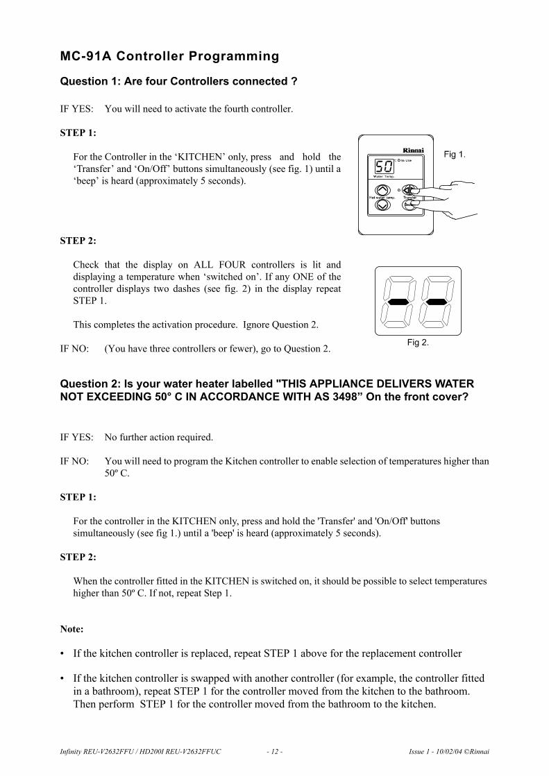
MC-91A Controller Programming
Question 1: Are four Controllers connected ?
IF YES: You will need to activate the fourth controller.
STEP 1:
For the Controller in the ‘KITCHEN’ only, press and hold the‘Transfer’ and ‘On/Off’ buttons simultaneously (see fig. 1) until a‘beep’ is heard (approximately 5 seconds).
STEP 2:
Check that the display on ALL FOUR controllers is lit anddisplaying a temperature when ‘switched on’. If any ONE of thecontroller displays two dashes (see fig. 2) in the display repeatSTEP 1.
This completes the activation procedure. Ignore Question 2.
IF NO: (You have three controllers or fewer), go to Question 2.
Question 2: Is your water heater labelled "THIS APPLIANCE DELIVERS WATER NOT EXCEEDING 50° C IN ACCORDANCE WITH AS 3498” On the front cover?
IF YES: No further action required.
IF NO: You will need to program the Kitchen controller to enable selection of temperatures higher than50º C.
STEP 1:
For the controller in the KITCHEN only, press and hold the 'Transfer' and 'On/Off' buttons simultaneously (see fig 1.) until a 'beep' is heard (approximately 5 seconds).
STEP 2:
When the controller fitted in the KITCHEN is switched on, it should be possible to select temperatures higher than 50º C. If not, repeat Step 1.
Note:
• If the kitchen controller is replaced, repeat STEP 1 above for the replacement controller
• If the kitchen controller is swapped with another controller (for example, the controller fitted in a bathroom), repeat STEP 1 for the controller moved from the kitchen to the bathroom. Then perform STEP 1 for the controller moved from the bathroom to the kitchen.
Fig 2.
Infinity REU-V2632FFU / HD200I REU-V2632FFUC - 12 - Issue 1 - 10/02/04 ©Rinnai

Infinity REU-V2632FFU / HD200I REU-V2632FFUC - 13 - Issue 1 - 10/02/04 ©Rinnai
6. Cutaway Diagram

7. Operational Flow Chart
Infinity REU-V2632FFU / HD200I REU-V2632FFUC - 14 - Issue 1 - 10/02/04 ©Rinnai

Infinity REU-V2632FFU / HD200I REU-V2632FFUC - 15 - Issue 1 - 10/02/04 ©Rinnai

Infinity REU-V2632FFU / HD200I REU-V2632FFUC - 16 - Issue 1 - 10/02/04 ©Rinnai
8. Operation Principles
Hot Water Operation
1. Ignition• Activate controllers (if fitted) and open the hot water tap (for full details regarding operation of
controllers refer to the ‘How To Use Your Water Heater’ booklet).• When water flows through the unit, the water flow sensor rotates and sends an electrical ‘pulse’ signal
to the Printed Circuit Board (PCB). This signal is proportional to the water flow rate.• The PCB sends electrical current to the combustion fan motor causing it to turn. The fan motor sends
an electrical pulse signal to the PCB. If fan rotation is OK, the main solenoid and changeover solenoidvalves open as required, the spark generator activates and the spark electrode ignites the burner.
2. Water Temperature / Flow Control / Volume Control• The PCB will automatically control operation of the internal components to achieve the programmed
temperature. When a high temperature rise is required, the PCB may cause the Water Flow Servo toclose partially resulting in a lower flow rate to achieve the programmed temperature. This is anecessary operational feature of the unit.
• When operating in ‘Bath Fill’ mode, the signal from the water flow sensor is also used by the PCB tocompute the volume of water that has been passed through the unit at any instant whilst the bath isfilling.
3. Shut Down• When operating in ‘Bath Fill’ mode, the PCB causes the Water Flow Servo to close when the
programmed Bath Fill volume has passed through the unit. Alternatively, flow is stopped when theuser closes the hot water tap.
• When water flow stops, the water flow sensor stops rotating and the pulse signal to the PCB stops. ThePCB then causes the main solenoid and solenoid valves to close and the burner is extinguished. Thecombustion fan will continue to operate for some time to purge the combustion chamber.
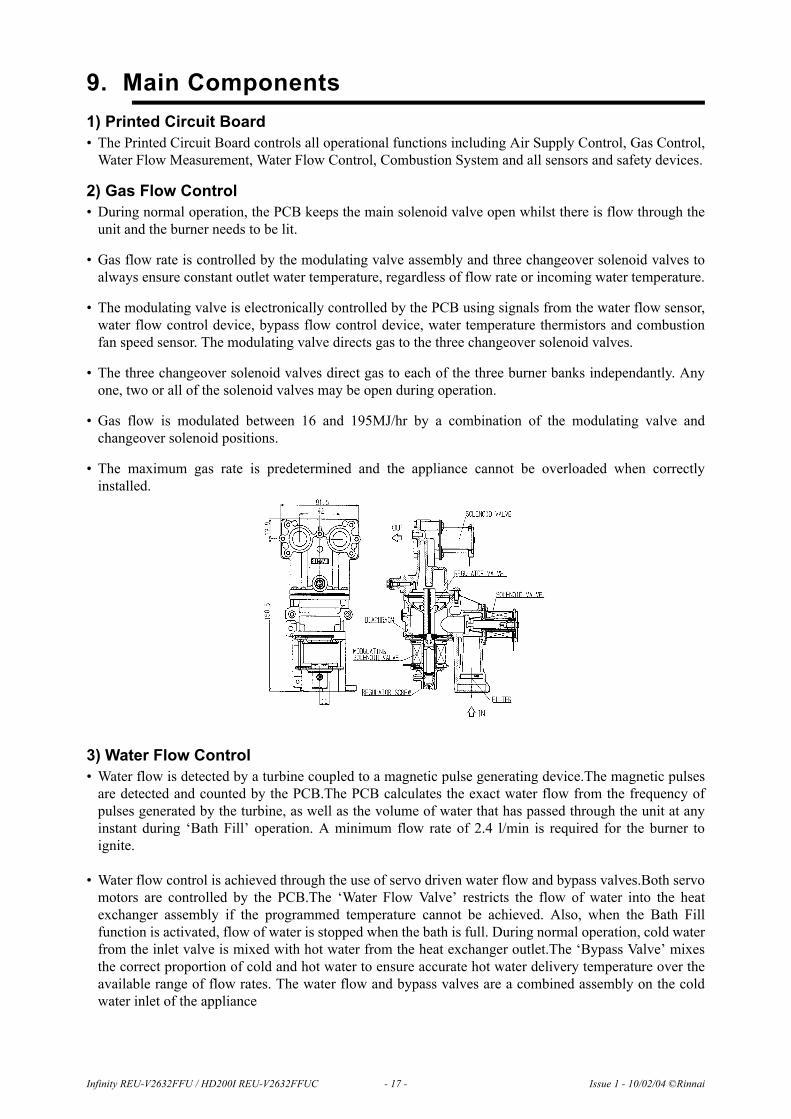
9. Main Components1) Printed Circuit Board• The Printed Circuit Board controls all operational functions including Air Supply Control, Gas Control,
Water Flow Measurement, Water Flow Control, Combustion System and all sensors and safety devices.
2) Gas Flow Control• During normal operation, the PCB keeps the main solenoid valve open whilst there is flow through the
unit and the burner needs to be lit.
• Gas flow rate is controlled by the modulating valve assembly and three changeover solenoid valves toalways ensure constant outlet water temperature, regardless of flow rate or incoming water temperature.
• The modulating valve is electronically controlled by the PCB using signals from the water flow sensor,water flow control device, bypass flow control device, water temperature thermistors and combustionfan speed sensor. The modulating valve directs gas to the three changeover solenoid valves.
• The three changeover solenoid valves direct gas to each of the three burner banks independantly. Anyone, two or all of the solenoid valves may be open during operation.
• Gas flow is modulated between 16 and 195MJ/hr by a combination of the modulating valve andchangeover solenoid positions.
• The maximum gas rate is predetermined and the appliance cannot be overloaded when correctlyinstalled.
3) Water Flow Control• Water flow is detected by a turbine coupled to a magnetic pulse generating device.The magnetic pulses
are detected and counted by the PCB.The PCB calculates the exact water flow from the frequency ofpulses generated by the turbine, as well as the volume of water that has passed through the unit at anyinstant during ‘Bath Fill’ operation. A minimum flow rate of 2.4 l/min is required for the burner toignite.
• Water flow control is achieved through the use of servo driven water flow and bypass valves.Both servomotors are controlled by the PCB.The ‘Water Flow Valve’ restricts the flow of water into the heatexchanger assembly if the programmed temperature cannot be achieved. Also, when the Bath Fillfunction is activated, flow of water is stopped when the bath is full. During normal operation, cold waterfrom the inlet valve is mixed with hot water from the heat exchanger outlet.The ‘Bypass Valve’ mixesthe correct proportion of cold and hot water to ensure accurate hot water delivery temperature over theavailable range of flow rates. The water flow and bypass valves are a combined assembly on the coldwater inlet of the appliance
Infinity REU-V2632FFU / HD200I REU-V2632FFUC - 17 - Issue 1 - 10/02/04 ©Rinnai

.
4) Air Supply Control• Air for combustion is supplied by a centrifugal fan driven by a variable speed DC motor. The voltage to
the motor is determined by the PCB based on water flow, delivered water temperature and programmedwater temperature. The actual fan speed is monitored by a magnetic pulse counter. This counter emits asignal to the PCB. From the voltage supplied to the DC motor and the fan speed signal, the PCBdetermines whether an error condition exists with the fan.
5) Combustion SystemThe combustion chamber is housed within the heat exchanger assembly and comprises:• A three chamber aluminium alloy manifold with a total of 44 integral injectors, arranged in two rows of
twenty two. The middle chamber houses eight injectors, the left chamber, twelve, and the right chamber,twenty four injectors. Gas flow to each chamber is controlled by an electronic solenoid valve (refer ‘GasFlow Control’ above).
• A burner assembly comprising twenty two identical modular stainless steel bunsen burners secured byan aluminised steel framework. The manifold is attached to the front of the burner module. Each bunsenburner is supplied by two injectors.
• A combustion chamber. Integrated into the combustion chamber front panel are the flame rod and twoignition electrodes.
Infinity REU-V2632FFU / HD200I REU-V2632FFUC - 18 - Issue 1 - 10/02/04 ©Rinnai

Infinity REU-V2632FFU / HD200I REU-V2632FFUC - 21 - Issue 1 - 17/03/05 ©Rinnai
10. Time ChartsNormal Combustion
Mis-Ignition / Flame Failure
Abnormal Pre-Purge (Air Supply/Exhaust Blockage)

Infinity REU-V2632FFU / HD200I REU-V2632FFUC - 20 - Issue 1 - 10/02/04 ©Rinnai
11. Wiring Diagram
Infinity REU-V2632FFU / HD200I REU-V2632FFUC - 11 - Issue 1 - 16/05/05 ©Rinnai
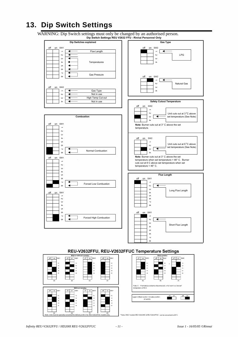
13. Dip Switch SettingsWARNING: Dip Switch settings must only be changed by an authorised person.
off on SW1 off on SW2
1 1
2 2
3 3
4 4
56
78
off on SW2
12
off on SW2
3
1 4
23
4
off on SW2
123
4
off on SW1
12
34
off on SW2
5 1
6 2
7 3
8 4
off on SW1
12
345
6off on SW1
7 1
8 23
off on SW1
4
1 5
2 6
3 7
4 8
56
off on SW1
7 1
8 23
45
678
Forced Low Combustion
Safety Cutout Temperature
Flue Length
Unit cuts out at 6oC above
set temperature (See Note)
Long Flue Length
Short Flue Length
Gas Pressure
Not in use
High Temp Cut-out
Normal Combustion
Gas Type
Not in use
Combustion
Forced High Combustion
Dip Switch Settings REU V2632 FFU - Rinnai Personnel Only
Dip Switches explained Gas Type
LPG
Flue Length
Temperatures
Natural Gas
Unit cuts out at 3oC above
set temperature (See Note)
Note: Burner cuts out at 3° C above the set
temperature.
Note: Burner cuts out at 3° C above the set
temperature when set temperature > 46° C. Burner
cuts out at 6 C above set temperature when set
temperature < 46° C.
Note: Unit must be specially converted for delivery at 85 C for REU-V2632FFUC models only. * Note: ONLY models REU V2632WC & REU V2632FFUC can be converted to 85°C.

13. Fault Finding
If there is a fault with the appliance, and controllers are installed, a numerical fault code may appear on thedigital display controller. If controllers are not installed, one may be fitted to find out the fault code. Faultfinding without controllers (and thus fault codes) is possible but more time consuming.
To diagnose and rectify faults, the Fault Finding Table is used as illustrated below:
Fault Finding TableDescribes possible faults
and error codes. (page 23)
Operational Flow Chart
(page 14)
Component Circuit Value TableSummarises running and standby electrical values
for all components. (page 24)
Wiring Diagram(page 20) Maintenance
Monitor / Error History
Provides accumulated number of startups,
combustion time, history of operational faults and
readout of electrical values whilst unit
operational.(page 37)
Component and Circuit Check
ProceduresDetailed information on how to check all
components.(page 30)
Dismantling for Service
Detailed information on how to remove and
replace components.(page 45)
Infinity REU-V2632FFU / HD200I REU-V2632FFUC - 22 - Issue 1 - 10/02/04 ©Rinnai

Fault Finding Table
Code on Controller Fault Table Action
03Power interruption during Bathfill. Water will not flow when power restored.
1. Turn off all hot water taps.1. Press the ON/OFF button on a controller twice.
10Combustion fan current too high. Unit operates, then stops.
E 1. Check blockage of air intake/flue outlet.2. Check combustion fan.
11No ignition. Unit stops without flame igniting
C1. Check gas supply2. Check sparker unit3. Check gas valves
12
Flame Failure / Earth Leakage 1. Check gas supply2. Check flame rod3. Check earth wire lead4. Check remote control
14
Thermal fuse and/or overheat switch activated. Unit operates, then stops.
1. Check thermal fuse2. Check overheat switchIMPORTANT- If thermal fuse or overheat switch were faulty :a. Check heater for damageb. Confirm “Gas Type” and “Combustion” dip switch settings (page 21)c. Confirm test point pressures (page 34).
16
Over temperature warning. Unit operates, then stops.
1. Confirm “Gas Type” and “Combustion” dip switch settings (page 21)2. Confirm test point pressure (page 34)
C 3. Check gas valves
D 4. Check water flow sensor
B 5. Check water flow servo
A 6. Check heat exchanger outlet temperature thermistor7. Check hot water outlet temperature thermistor
32 Outlet water thermistor flow A Check hot water outlet thermistor
33 Heat exchanger thermistor error A Check heat exchanger thermistor
52 Modulating solenoid valve fault. Unit stops without flame ignition.
C Check modulating solenoid valve
61 Combustion fan rotation error E Check combustion fan
65 Water flow control device error. Water flow is not controlled. Water temperature too low.
B Check water flow servo
71 Solenoid valve circuit error. Unit does not operate. C Check gas valves
72 Flame rod circuit error. Unit does not operate. Check flame rod
-
Appliance does not operate at all. No display on the remote controllers (if fitted).
1. Check power cord plugged in and supply turned on.2. Check power supply voltage.3. Check electrical fuse.4. Check transformer.
C 5. Check gas valves
6. Check sparker unit.7. Check earth leads and connections.8. Check for short circuits.9. Check remote controller(s) - if fitted.
-
No combustion despite remote control indicating that combustion is occuring - if remote controller(s) fitted.
D 1. Check water flow sensor.
2. Check flame rod.
A 3. Check heat exchanger outlet thermistor.
A 4. Check hot water outlet thermistor.
E 5. Check combustion fan.
6. Check the sparker unit.
C 7. Check gas valves.
8. Check thermal fuse.9. Check overheat switch.IMPORTANT - If thermal fuse or overheat switch were faulty:a) check heater for damage;b) confirm “Gas Type” and “Combustion” dip switch settings;c) confirm test point pressure.
-Combustion stops during operation. 1. Check gas supply
2. Check flame rod3. Check earth leads and connections.
-
Cannot adjust the hot water temperature via the controller(s) - only if controller(s) fitted.
A 1. Check hot water outlet thermistor.
2. Check heat exchanger outlet thermistor.
C 3. Check gas valves
B 4. Check water flow servo.
5. Check bypass servo.
-Anti-frost heater does not operate. F 1. Check anti-frost heater components
2. Check frost sensing switch
Infinity REU-V2632FFU / HD200I REU-V2632FFUC - 23 - Issue 1 - 10/02/04 ©Rinnai

Infinity REU-V2632FFU / HD200I REU-V2632FFUC - 24 - Issue 1 - 10/02/04 ©Rinnai
14. Component Circuit Value Table
CN Wire Colour
Surge Protection F5 B-Br AC207~264V
R-B DC11~13V Operate Electricity
Gy-Or DC11~13V Control Electricity
Below DC1V (Limiter On)
DC4~6V (Limiter Off)
Below DC1V (Limiter On)
DC4~6V (Limiter Off)
Br-W
Or-WDC2~6V Operate Condition
Y-W
R-W GND15~35
Remote Control D1 Bk-Bk DC11~13V
R-Bk DC11~13V
Y-Bk GND DC4~7V (Pulse 17~460Hz)
R-Bk DC6~45V
Y-Bk DC11~13V
W-Bk GND DC5~10V (33~400Hz)
Y-BODY EARTH AC5~150V After Ignition
Y-FLAME ROD Over DC1µA Flame Condition
C Modulating Valve C2 P-PDC2~15V
67~81
B5
B6
Air Thermistor B1 W-W
B3
C3
Igniter F6 Gy-Gy AC90~110V
Main Solenoid Valve E1 P-BkDC80~100V
1.7~2.1k
Solenoid Valve 1 E2 Y-BkDC80~100V
1.7~2.1k
Solenoid Valve 2 E3 B-BkDC80~100V
1.7~2.1k
Solenoid Valve 3 E4 Br-BkDC80~100V
1.7~2.0k
F5 B-Br 16~18
F7 W-Bk AC90~110V
Valve Heater F3 50~56k
F2 Y-Y
F3 Y-Y
C
F
A
Transformer
Thermal Fuse R-R
444~510k
D
Combustion Fan
Below 1
Outgoing Thermistor
Heat Exchanger
Outgoing Thermistor
W-W
15° C··· 11.4 ~14.0k
30° C··· 6.4 ~ 7.8k
5° C··· 3.6 ~ 4.5k
60° C··· 2.2 ~ 2.7k
100° C··· 0.6 ~ 0.8k
B
Valve Heater
and Square Heater
Flame Rod C1
By-Pass Flow
Control DeviceG1
E
Water Flow Sensor B4
Full Open Position
Full Close Position
Measurement Point
A1
Water Flow
Control DeviceB2
Gy-Br
Gy-Y
Table Reference Component Normal Value A Note

15. Component and Circuit Checks
1. Combustion Fan CircuitCheck the Motor
Check the combustion fan if the error indicator displays “61”.
Measure voltages between Black and Red of the PCB connector (A1).
Normal: DC6~45V (when fan ON)DC0V (when fan OFF)If normal proceed to check the rotation sensorFaulty: Replace PCB
Check for the Fan Rotation Sensor
a.) Measure voltages between Black and Yellow of connector (A1).Normal: DC11~13V If normal proceed to b.).Faulty: Replace PCB.
b.) Measure voltages between Black and White of connector (A1).Normal: DC5~10V If normal proceed to Sparker Circuit 2.Faulty: Replace Combustion Fan.
2. Sparker Circuita.) Measure voltages between Grey and Grey of connector (F6).
Normal: AC90~110VIf normal, proceed to b.).Faulty: Replace PCB.
b.) Disconnect connector (J6) and measure resistance between both terminals of the sparker.
Normal: 1MΩIf not sparking, adjust or replace ignition plug.Faulty: Replace Sparker.
Infinity REU-V2632FFU / HD200I REU-V2632FFUC - 25 - Issue 1 - 10/02/04 ©Rinnai

3a.Main Solenoid Valve (SV0) Circuit Check the main solenoid if error indicator “11” is displayed.
a.) Disconnect Main Solenoid connector (E1) and measure resistance between Pink and BlackNormal: 1.7~2.1kΩIf normal, proceed to b.).Faulty: Replace Main Solenoid.
b.) Measure voltage between Pink-Black of Main Solenoid connector.
Normal: DC80~100VIf normal, proceed to Solenoid Valve SV1 (E2) Faulty: Replace PCB.
3b.Solenoid Valve 1 (SV1) CircuitCheck Solenoid 1 if error indicator “11” is displayed.
a.) Disconnect Solenoid 1 connector (E2) and measure resistance between Yellow and Black.
Normal: 1.7~2.1kΩIf normal, proceed to b.).Faulty: Replace Solenoid 1.
b.) Measure voltage between Yellow and Black of Solenoid 1 connector.
Normal: DC80~100VIf normal, proceed to Solenoid Valve 2 (SV2) CircuitFaulty: Replace PCB.
3c. Solenoid Valve 2 (SV2) Circuita.) Disconnect Solenoid Valve 2 connector (E3) and measure resistance between Blue and Black.
Normal: 1.7~2.1kΩIf normal,, proceed to b.Faulty: Replace Solenoid Valve 2.
b.) Measure voltage between Blue and Black of Solenoid Valve connector.
Normal: DC80~100VIf normal, proceed to Thermal fuse Circuit.Faulty: Replace PCB.
Infinity REU-V2632FFU / HD200I REU-V2632FFUC - 26 - Issue 1 - 10/02/04 ©Rinnai
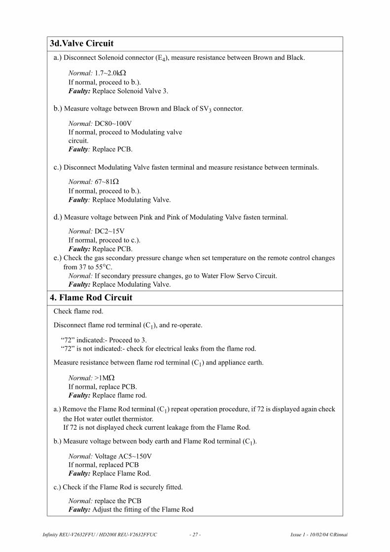
3d.Valve Circuita.) Disconnect Solenoid connector (E4), measure resistance between Brown and Black.
Normal: 1.7~2.0kΩIf normal, proceed to b.).Faulty: Replace Solenoid Valve 3.
b.) Measure voltage between Brown and Black of SV3 connector.
Normal: DC80~100VIf normal, proceed to Modulating valve circuit.Faulty: Replace PCB.
c.) Disconnect Modulating Valve fasten terminal and measure resistance between terminals.
Normal: 67~81ΩIf normal, proceed to b.).Faulty: Replace Modulating Valve.
d.) Measure voltage between Pink and Pink of Modulating Valve fasten terminal.
Normal: DC2~15VIf normal, proceed to c.).Faulty: Replace PCB.
e.) Check the gas secondary pressure change when set temperature on the remote control changes from 37 to 55°C.
Normal: If secondary pressure changes, go to Water Flow Servo Circuit.Faulty: Replace Modulating Valve.
4. Flame Rod CircuitCheck flame rod.
Disconnect flame rod terminal (C1), and re-operate.
“72” indicated:- Proceed to 3.“72” is not indicated:- check for electrical leaks from the flame rod.
Measure resistance between flame rod terminal (C1) and appliance earth.
Normal: >1MΩIf normal, replace PCB.Faulty: Replace flame rod.
a.) Remove the Flame Rod terminal (C1) repeat operation procedure, if 72 is displayed again check the Hot water outlet thermistor. If 72 is not displayed check current leakage from the Flame Rod.
b.) Measure voltage between body earth and Flame Rod terminal (C1).
Normal: Voltage AC5~150VIf normal, replaced PCBFaulty: Replace Flame Rod.
c.) Check if the Flame Rod is securely fitted.
Normal: replace the PCBFaulty: Adjust the fitting of the Flame Rod
Infinity REU-V2632FFU / HD200I REU-V2632FFUC - 27 - Issue 1 - 10/02/04 ©Rinnai
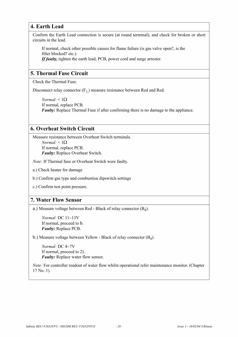
4. Earth Lead Confirm the Earth Lead connection is secure (at round terminal), and check for broken or short circuits in the lead.
If normal, check other possible causes for flame failure (is gas valve open?, is the filter blocked? etc.).If faulty, tighten the earth lead, PCB, power cord and surge arrester.
5. Thermal Fuse Circuit Check the Thermal Fuse.
Disconnect relay connector (F1,) measure resistance between Red and Red.
Normal: < 1ΩIf normal, replace PCB.Faulty: Replace Thermal Fuse if after confirming there is no damage to the appliance.
6. Overheat Switch CircuitMeasure resistance between Overheat Switch terminals.
Normal: < 1ΩIf normal, replace PCB.Faulty: Replace Overheat Switch.
Note: If Thermal fuse or Overheat Switch were faulty.
a.) Check heater for damage
b.) Confirm gas type and combustion dipswitch settings
c.) Confirm test point pressure.
7. Water Flow Sensora.) Measure voltage between Red - Black of relay connector (B4).
Normal: DC 11~13VIf normal, proceed to b.Faulty: Replace PCB.
b.) Measure voltage between Yellow - Black of relay connector (B4).
Normal: DC 4~7VIf normal, proceed to 2).Faulty: Replace water flow sensor.
Note: For controller readout of water flow whilst operational refer maintenance monitor. (Chapter 17 No. 1).
Infinity REU-V2632FFU / HD200I REU-V2632FFUC - 28 - Issue 1 - 10/02/04 ©Rinnai

8. Water Flow Servo Circuita.) Disconnect relay connector (B2), and measure voltage between Red and Blue on water flow
servo.
Normal: 10~30ΩIf normal: proceed to b.).Faulty: Replace Water Flow Servo and Water Flow Sensor.
b.) Disconnect relay connector (B2), and measure voltage between Orange (+) and Grey (-) on PCB unit side.
Normal: DC11~13VIf Normal: proceed to c.).Faulty: Replace PCB unit.
c.) Measure voltage between Brown and Grey with relay connector (B2) connected (with no water flowing, water flow servo fully open).
Normal: < DC4~6VFaulty: Replace Water Flow Servo and Water Flow Sensor.
d.) Measure voltage between Yellow and Grey with relay connector (B2) connected (with no water flowing, water flow servo fully open).
Normal: < DC1.0VFaulty: Replace Water Flow Servo and Water Flow Sensor.
9. Heat Exchanger Outlet Thermistor Circuit Check Heat Exchanger Thermistor if error code “33” is displayed.
Disconnect relay connector (B6) and measure resistance between White -White.
Circuit break: Resistance >1MΩShort circuit: Resistance > 1 ΩNormal: Check Heat exchanger outlet thermistorFaulty: Replace heat exchanger outlet thermistor.
Note: For controller readout of thermistor temperature whilst operational refer maintenance monitor.
Infinity REU-V2632FFU / HD200I REU-V2632FFUC - 29 - Issue 1 - 10/02/04 ©Rinnai
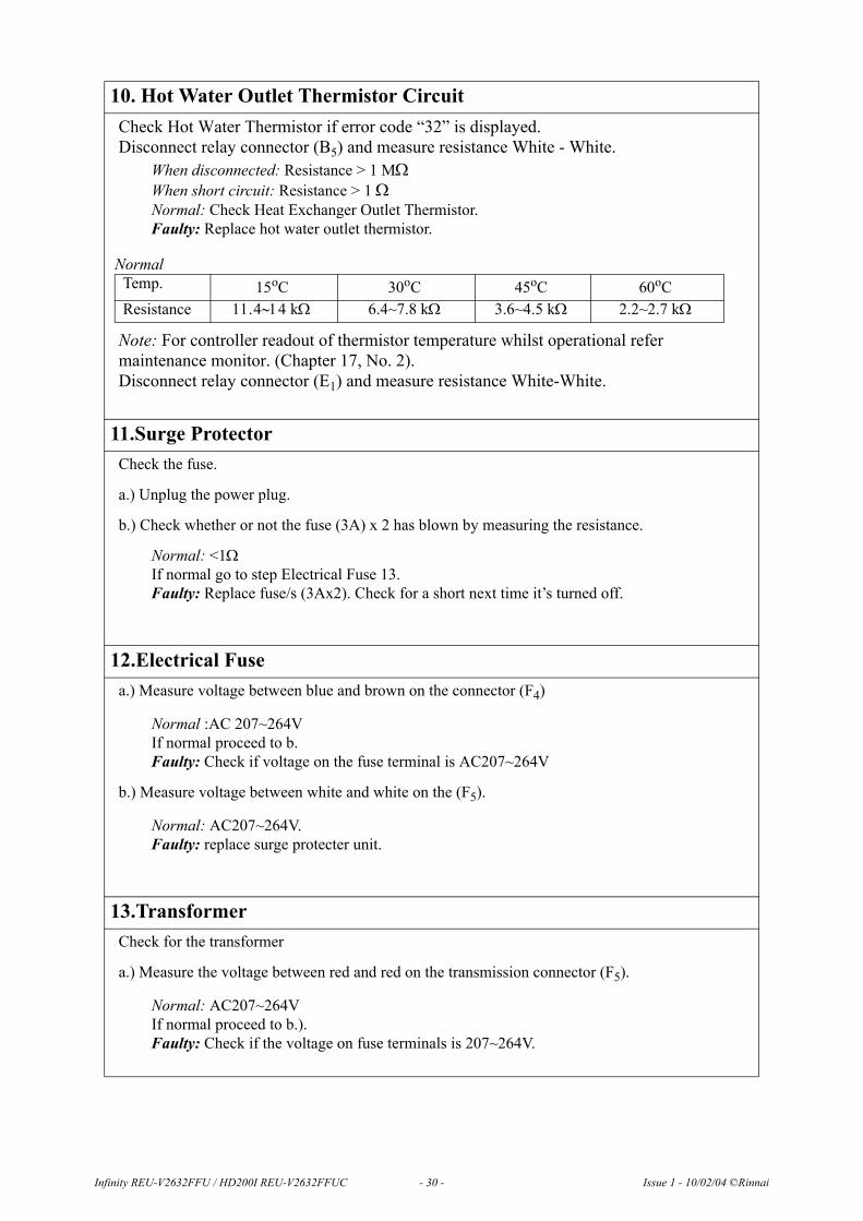
10. Hot Water Outlet Thermistor CircuitCheck Hot Water Thermistor if error code “32” is displayed.Disconnect relay connector (B5) and measure resistance White - White.
When disconnected: Resistance > 1 MΩWhen short circuit: Resistance > 1 ΩNormal: Check Heat Exchanger Outlet Thermistor.Faulty: Replace hot water outlet thermistor.
Note: For controller readout of thermistor temperature whilst operational refer maintenance monitor. (Chapter 17, No. 2).Disconnect relay connector (E1) and measure resistance White-White.
11.Surge ProtectorCheck the fuse.
a.) Unplug the power plug.
b.) Check whether or not the fuse (3A) x 2 has blown by measuring the resistance.
Normal: <1ΩIf normal go to step Electrical Fuse 13.Faulty: Replace fuse/s (3Ax2). Check for a short next time it’s turned off.
12.Electrical Fusea.) Measure voltage between blue and brown on the connector (F4)
Normal :AC 207~264VIf normal proceed to b.Faulty: Check if voltage on the fuse terminal is AC207~264V
b.) Measure voltage between white and white on the (F5).
Normal: AC207~264V.Faulty: replace surge protecter unit.
13.TransformerCheck for the transformer
a.) Measure the voltage between red and red on the transmission connector (F5).
Normal: AC207~264V If normal proceed to b.).Faulty: Check if the voltage on fuse terminals is 207~264V.
Normal Temp. 15oC 30oC 45oC 60oCResistance 11.4∼14 kΩ 6.4~7.8 kΩ 3.6~4.5 kΩ 2.2~2.7 kΩ
Infinity REU-V2632FFU / HD200I REU-V2632FFUC - 30 - Issue 1 - 10/02/04 ©Rinnai

b.) Measure the voltage of the connector on the PCB.
Normal: Between Brown and Grey AC 30~50VBetween Yellow and Grey AC 180~220VIf normal, proceed to c.).Faulty: Replace transformer.
c.) Measure voltage between White and Black of connector (F) on PCB.
Normal: AC 12~18VIf normal, proceed to 4.Faulty: Replace transformer.
Note) The above transformer voltages are measured while the appliance is in standby mode - not while it is operating.
14. Bypass Servo Circuit 15.a.) Disconnect relay connector (G1) and measure resistance.
If normal, proceed to b.).Faulty: Replace PCB.
b.) Measure working voltage while relay connector (G1) is connected.
Faulty: Replace Bypass Servo.
15.Remote Control Check the voltage between the 2-core remote control cable.
Measure the voltage between terminals on the remote control terminal (D1).
Normal: DC 11~13VIf normal, replace the remote control after confirming that the cable hasn’t been damaged or shorted.Faulty: Because normal voltage is not given due a short circuit, despite the PCB being in normal state, check Water Flow Servo circuit.If solution is not given from the above replace PCB.
Normal CN Wire Colour Value
G1
Br - WO - WY - WR - WGND
15~35Ω
Normal CN Wire Colour Value
G1
Br - WO - WY - WR - WGND
DC 2~6V
Infinity REU-V2632FFU / HD200I REU-V2632FFUC - 31 - Issue 1 - 10/02/04 ©Rinnai

16. Maintenance Monitor / Error History
This feature is available where the appliances are connected with a deluxe controller (MC70 orBC70). This will enable service personnel to locate the maintenance history and faulty components,with the appliance in operation.
NB. When the maintenance information, error history is shown, use only one controller. If two or moreremote controls are used at the same time, it may not operate correctly.
To display Maintenance Information
Note: REU-V2632FFU uses Maintenance Numbers 1-12.
*Note 1 Fan Frequency rpm Conversion(rpm) = (Hz) x15
*Note 2 Remote Control Connections
16. With the controller in the "OFF" position press the Water Temperature "DOWN" (Cooler) button while holding the "ON/OFF" button to activate the maintenance monitor. Press the "ON/OFF" button a second time to set the controller in the "ON" mode. This feature can now be used with the appliance in operation.
17. The maintenance number will be shown in the Water Temperature display.
18. Data will be shown in the Clock display.
19. To select the required maintenance number, press the Water Temperature "UP" and "DOWN" buttons.
Display Monitor Contents No. Contents Units Data Range01 Water flow sensor recognition flow
(Example 123 = 12.3L/min).0.1L/min 0~400
02 Hot water Outlet thermistor temperature(Example 20 = 20 C)
C 0~999
03 Hot water combustion time(Example 6 = 600 hours)
100 hours 000~999
04 Hot water operation frequency(Example 6 = 600 Operations)
100 0~999
05 Hot water fan frequency Hz pulses/sec 0~999 *Note 1
06 Remote control connection none 0 or 1 *Note 2
Bathroom Remote
Additional remote Kitchen remote
“0 1 1”
Controls connected Display
No “0”
Yes “1”
07 Water flow servo present recognising positioning None 0~2 *Note 3
°°
Infinity REU-V2632FFU / HD200I REU-V2632FFUC - 32 - Issue 1 - 10/02/04 ©Rinnai

*Note 3 Water Flow Servo Positioning
To return to normal operation• Press the ON/OFF button again while holding down the Water Temperature "DOWN" (Cooler)
button.
To return to normal operation.
• Press the ON/OFF button again while holding the Water Temperature “UP” (Hotter) button.
• This feature will automatically shut down after 3 minutes.
Servo Position Open Centre ClosedDisplay “1” “0” “2”
08 Inlet water temperature(PCB recognition value)(Example 25 = 25 C)
C 0~999
09 Hot water fan current flow value(Example 6 x 10 = 60 mA)
10 mA 0~999
10 Bath fill amount (this counts the litres during bath fill operation).
Litres 0~999
11 Heat exchanger exit thermistor temperature Example 55 = 55 C)
C 0~999
12 Bypass servo present recognition positioning(Example 0 = Closed
160 = Half open 320 = Open
Degrees 0~320
Error History
To Display Error Memory (History)(This feature will show the last 10 faults in sequence) 1. Turn off at the ON/OFF button. (This can be done during
operation)
2. Press the ON/OFF button while holding the Water Temperature "UP" (Hotter) button.
• The Sequence will be shown in the Water Temperature display.
• Error Code will be shown in the Clock display. (See service Manual for error codes).
• Where there are less than a total of 9 errors, "FFF" or " - - " will be displayed in the Clock display.
°
°
°°
Infinity REU-V2632FFU / HD200I REU-V2632FFUC - 33 - Issue 1 - 10/02/04 ©Rinnai

17. Gas Pressure Setting Procedure
The regulator on the Infinity is electronically controlled and factory pre-set. Under normalcircumstances it does not require adjustment during installation. Perform this procedure only if the unitis not operating correctly and all other possible causes for incorrect operation have been eliminated.
1) Turn 'OFF' the gas supply
2) Turn 'OFF' 240V power supply.
3) Remove the front cover from the appliance.
4) Check gas type switches (fig. 1) are in the correct position (top set or SW1 of switches).
5) Attach pressure gauge to burner test point. (fig. above right)
6) Turn 'ON' the gas supply.
7) Turn 'ON' 240V power supply.
8) If remote controllers are fitted, turn the unit 'ON' at the kitchen controller, select a delivery temperature of 55°C and open a hot water tap fully. (CAUTION: Ensure building occupants do not have access to hot water outlets during this procedure.
9) Set the Infinity to 'Forced Low' combustion by setting No. 7 dipswitch of the bottom (SW2) set of dip switches to 'ON'. (fig.3)
10) Check the burner test point pressure.
Infinity REU-V3232W /HD250E REU-V3232WC - 34 - Issue 1 - 10/02/04 ©Rinnai
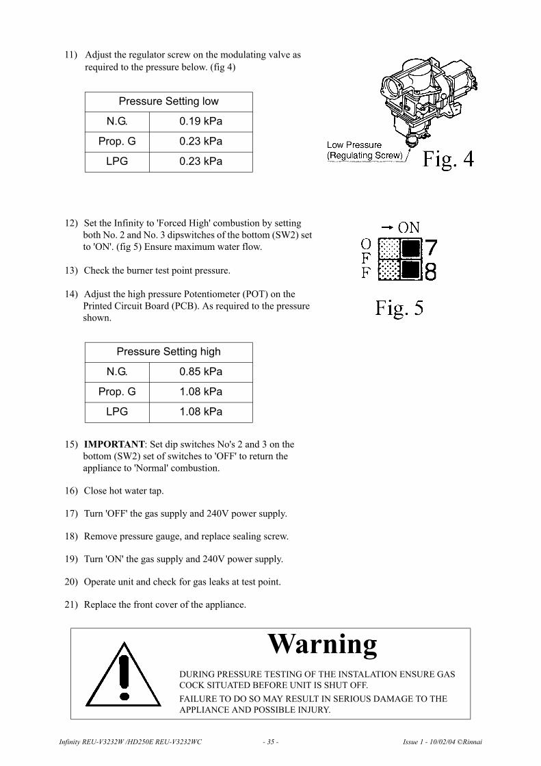
11) Adjust the regulator screw on the modulating valve as required to the pressure below. (fig 4)
Pressure Setting low
N.G. 0.19 kPa
Prop. G 0.23 kPa
LPG 0.23 kPa
12) Set the Infinity to 'Forced High' combustion by setting both No. 2 and No. 3 dipswitches of the bottom (SW2) set to 'ON'. (fig 5) Ensure maximum water flow.
13) Check the burner test point pressure.
14) Adjust the high pressure Potentiometer (POT) on the Printed Circuit Board (PCB). As required to the pressure shown.
Pressure Setting high
N.G. 0.85 kPa
Prop. G 1.08 kPa
LPG 1.08 kPa
15) IMPORTANT: Set dip switches No's 2 and 3 on the bottom (SW2) set of switches to 'OFF' to return the appliance to 'Normal' combustion.
16) Close hot water tap.
17) Turn 'OFF' the gas supply and 240V power supply.
18) Remove pressure gauge, and replace sealing screw.
19) Turn 'ON' the gas supply and 240V power supply.
20) Operate unit and check for gas leaks at test point.
21) Replace the front cover of the appliance.
WarningDURING PRESSURE TESTING OF THE INSTALATION ENSURE GAS COCK SITUATED BEFORE UNIT IS SHUT OFF.FAILURE TO DO SO MAY RESULT IN SERIOUS DAMAGE TO THE APPLIANCE AND POSSIBLE INJURY.
Infinity REU-V3232W /HD250E REU-V3232WC - 35 - Issue 1 - 10/02/04 ©Rinnai
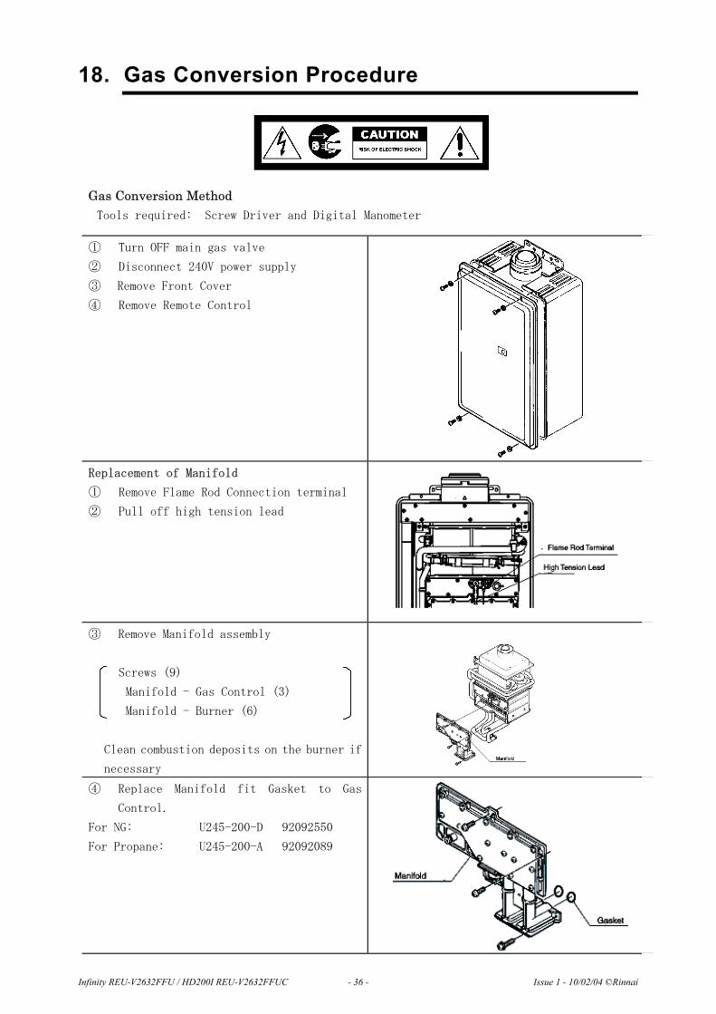
18. Gas Conversion Procedure
Gas Conversion Method Tools required: Screw Driver and Digital Manometer
① Turn OFF main gas valve
② Disconnect 240V power supply
③ Remove Front Cover
④ Remove Remote Control
Replacement of Manifold
① Remove Flame Rod Connection terminal
② Pull off high tension lead
③ Remove Manifold assembly
Screws (9)
Manifold - Gas Control (3)
Manifold - Burner (6)
Clean combustion deposits on the burner if
necessary
④ Replace Manifold fit Gasket to Gas
Control.
For NG: U245-200-D 92092550
For Propane: U245-200-A 92092089
Infinity REU-V2632FFU / HD200I REU-V2632FFUC - 36 - Issue 1 - 10/02/04 ©Rinnai
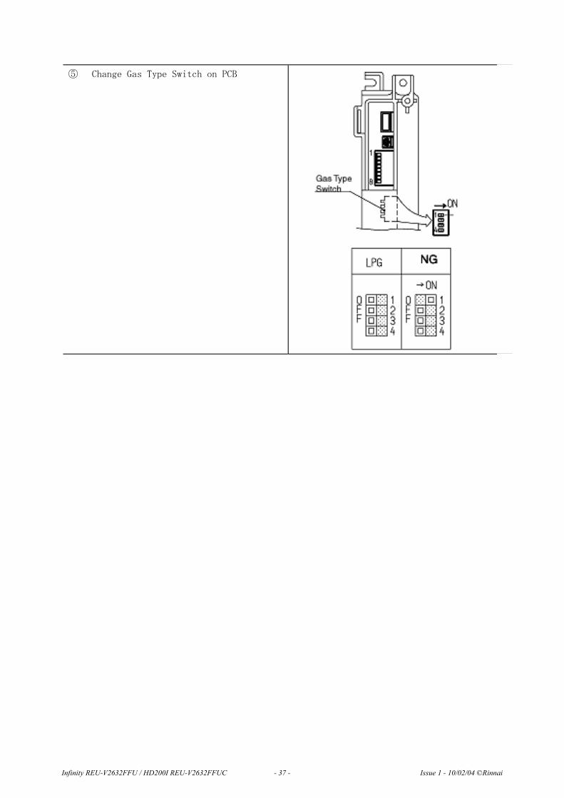
⑤ Change Gas Type Switch on PCB
Infinity REU-V2632FFU / HD200I REU-V2632FFUC - 37 - Issue 1 - 10/02/04 ©Rinnai

Pressure Setting
① Remove pressure test point sealing screw
from gas control
② Connect digital manometer with test
point
③ Turn ON 240V power supply
④ Turn ON remote controller switch
⑤ Turn ON main gas valve fully
⑥ Change Dipswitch No. 7 for low combustion
⑦ Turn ON outgoing water tap
⑧ Set pressure low with solenoid valve
adjustment
Low Capacity
(kPa)
N.G. 0.19
Prop.G 0.23
Infinity REU-V2632FFU / HD200I REU-V2632FFUC - 38 - Issue 1 - 10/02/04 ©Rinnai
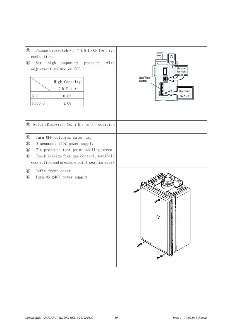
⑨ Change Dipswitch No. 7 & 8 to ON for high
combustion.
⑩ Set high capacity pressure with
adjustment volume on PCB
⑪ Return Dipswitch No. 7 & 8 to OFF position
⑫ Turn OFF outgoing water tap
⑬ Disconnect 240V power supply
⑭ Fit pressure test point sealing screw
⑮ Check leakage from gas control, manifold
connection and pressure point sealing screw
⑯ Refit front cover
⑰ Turn ON 240V power supply
High Capacity
( k P a )
N.G. 0.85
Prop.G 1.08
Infinity REU-V2632FFU / HD200I REU-V2632FFUC - 39 - Issue 1 - 10/02/04 ©Rinnai
Gas Conversion
Anti Frost Heater Installation
Fitting method
1. Turn off and disconnect the 240V power supply.
2. Turn off the water supply and relieve the water pressure in the water heater.
3. Remove front cover.
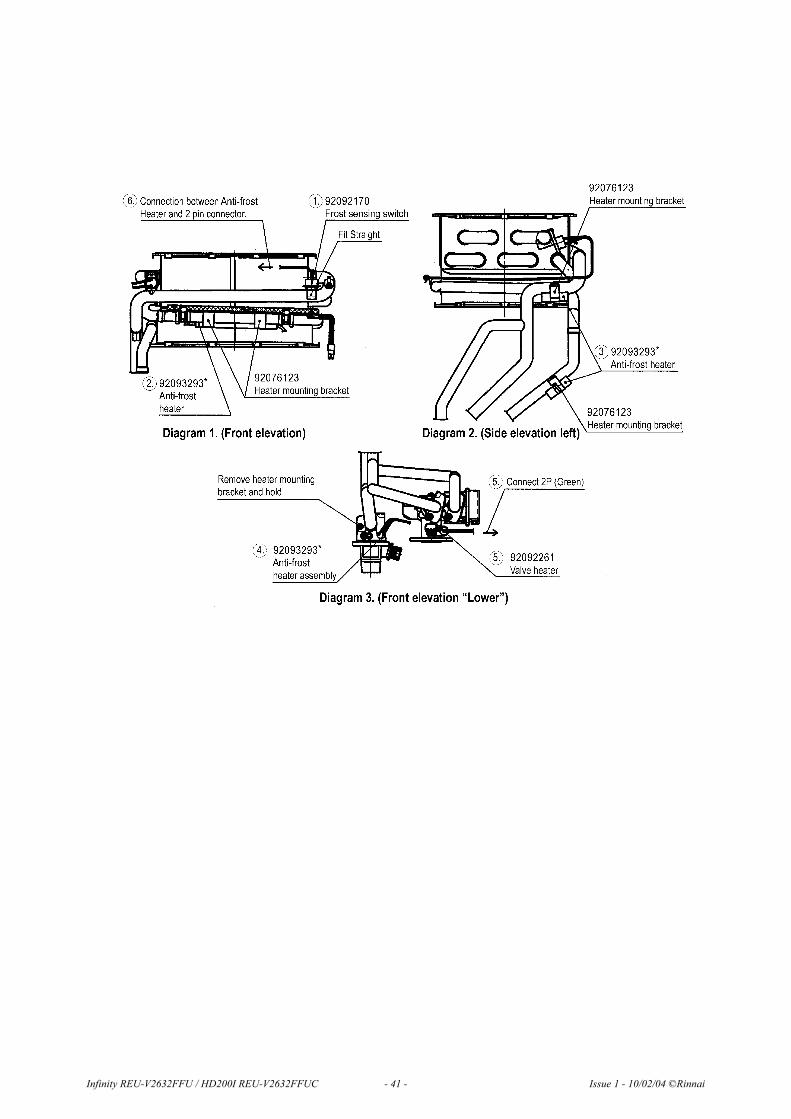
4. Fit the Frost sensing switch (92092170). This is the black sensor with the built in brackets and clips vertically on the
water tube at the top right hand side of the heat exchanger next to the thermistor. (See note 1 , Diagram 1).
5. Fit the long white round Anti-frost heater (92093293*) with two hook brackets (92076123) to the lower tube on the
front of the heat exchanger. (See note 2 , Diagram 1)
6. Using the clip brackets (92093301) fit the two square Anti-frost heaters (92093293*), one heater is to be fitted under
the hot water outlet tube while the other is to be fitted one along the side of the cold inlet tube. These are located on
the left hand side of the heat exchanger and can be easily accessed without removing any components. (See note 3 ,
Diagram 2)
7. On the hot water outlet connection block located in the lower left hand side, carefully loosen the screw retaining the
stainless steel bracket. Without disturbing the water seal twist the bracket anti-clockwise to clear the hole in the block,
insert heating element (92093293*), refit bracket and tighten the retaining screw. (See note 4 , Diagram 3)
8. On the cold water inlet servo valve located in the lower center of the unit, remove the retaining screw insert the Valve
heating element (92092261) refit the retaining screw. (See note 5 , Diagram 3)
9. Ensure all polarized plugs are connected and support wiring loom in existing anchor ties.
10. Connect the Anti-frost wiring loom (92093293*) to the polarized plug on the main 240V loom located directly after
the fuse holders.
11. Turn on water supply and ensure there are no water leaks on the hot water outlet joint.
12. Refit the front cover.
13. Restore the power supply.
Part RA Part Number Drawing Number Qty.
Frost sensing switch 92092170 U242-511 1
Anti-frost loom/heaters* 92093293 U245-775 1
Valve heater 92092261 U245-776 1
Heater mounting bracket 92093301 CF29-742X01 2
Heater mounting bracket 92076123 AU100-721X03 2
*Note: Anti-frost wiring loom is supplied with four factory fitted heating elements.
Infinity REU-V2632FFU / HD200I REU-V2632FFUC - 40 - Issue 1 - 10/02/04 ©Rinnai
Infinity REU-V2632FFU / HD200I REU-V2632FFUC - 41 - Issue 1 - 10/02/04 ©Rinnai

19. Dismantling for Service
240 Volt potential exposure. Isolate the appliance and reconfirm with a neon screwdriver or multimeter.
Item Page1. “Removal of the Front Panel” . . . . . . . . . . . . . . . . . . . . . . . . . . . . . . . . . . . . . . . . . . . . 43
2. “Removal of the PCB Unit” . . . . . . . . . . . . . . . . . . . . . . . . . . . . . . . . . . . . . . . . . . . . . 43
3. “Removal of the Water Flow Sensor, Servo and Bypass Servo”. . . . . . . . . . . . . . . . . . 43
4. “Removal of the Bypass Servo” . . . . . . . . . . . . . . . . . . . . . . . . . . . . . . . . . . . . . . . . . . 44
5. “Removal of Transformer” . . . . . . . . . . . . . . . . . . . . . . . . . . . . . . . . . . . . . . . . . . . . . . 54
6. “Removal of Sparker” . . . . . . . . . . . . . . . . . . . . . . . . . . . . . . . . . . . . . . . . . . . . . . . . . . 55
7. “Removal of the manifold and burner unit” . . . . . . . . . . . . . . . . . . . . . . . . . . . . . . . . . 44
8. “Removal of the Gas Control”. . . . . . . . . . . . . . . . . . . . . . . . . . . . . . . . . . . . . . . . . . . . 56
9. “Removal of Flame rod and spark plug” . . . . . . . . . . . . . . . . . . . . . . . . . . . . . . . . . . . . 56
10. “Removal of outgoing water thermistor” . . . . . . . . . . . . . . . . . . . . . . . . . . . . . . . . . . . 55
11. “Removal of heat exchanger thermistor” . . . . . . . . . . . . . . . . . . . . . . . . . . . . . . . . . . . 59
12. “Removal of air intake thermistor” . . . . . . . . . . . . . . . . . . . . . . . . . . . . . . . . . . . . . . . . 59
13. “Removal of Bypass Servo” . . . . . . . . . . . . . . . . . . . . . . . . . . . . . . . . . . . . . . . . . . . . . 47
14. “Removal of Anti Frost Switch” . . . . . . . . . . . . . . . . . . . . . . . . . . . . . . . . . . . . . . . . . . 47
15. “Removal of Anti Frost heater”. . . . . . . . . . . . . . . . . . . . . . . . . . . . . . . . . . . . . . . . . . . 48
16. “Removal of the Fan Motor” . . . . . . . . . . . . . . . . . . . . . . . . . . . . . . . . . . . . . . . . . . . . . 48
17. “Removal of Heat Exchanger” . . . . . . . . . . . . . . . . . . . . . . . . . . . . . . . . . . . . . . . . . . . 49
18. “Removal of Thermal Fuse” . . . . . . . . . . . . . . . . . . . . . . . . . . . . . . . . . . . . . . . . . . . . . 50
Unless otherwise stated, re-assembly is the reverse of dismantling.
Infinity REU-V2632FFU / HD200I REU-V2632FFUC - 42 - Issue 1 - 10/02/04 ©Rinnai
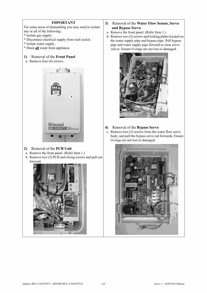
IMPORTANTFor some areas of dismantling you may need to isolate any or all of the following:* Isolate gas supply.* Disconnect electrical supply from wall socket.* Isolate water supply.* Drain all water from appliance.
1) Removal of the Front Panela. Remove four (4) screws.
2) Removal of the PCB Unita. Remove the front panel. (Refer Item 1.)b. Remove two (2) PCB unit fixing screws and pull out
forward.
3) Removal of the Water Flow Sensor, Servo and Bypass Servo
a. Remove the front panel. (Refer Item 1.)b. Remove two (2) screws and locking plates located on
the water supply pipe and bypass pipe. Pull bypass pipe and water supply pipe forward to clear servo valves. Ensure O-rings are not lost or damaged.
4) Removal of the Bypass Servoc. Remove two (2) screws from the water flow servo
body, and pull the bypass servo out forwards. Ensure O-rings are not lost or damaged.
Infinity REU-V2632FFU / HD200I REU-V2632FFUC - 43 - Issue 1 - 10/02/04 ©Rinnai

5) Removal of Transformera. Remove PCB (Refer to 2)b. Remove 100 V harness and 2-pin connection
c. Removal Transformer
6) Removal of Sparkera. Remove sparker b. Remove 3 pin connectorc. Remove high tension cord
7) Removal of the manifold and burner unita. Remove high tension cord and flame rod.b. Remove 2 pin connection of the solenoid valvec. Remove manifold.
Infinity REU-V2632FFU / HD200I REU-V2632FFUC - 44 - Issue 1 - 10/02/04 ©Rinnai

Manifold Assembly
a. Remove combustion chamber front panel.b. Remove burner unit.
c. Pull off burner unit
8) Removal of the Gas Controla. Remove manifold (refer to 5)b. Remove back tubec. Remove gas connection.
d. Pull off connectors for gas control modulation valve and solenoid valve.
Infinity REU-V2632FFU / HD200I REU-V2632FFUC - 45 - Issue 1 - 10/02/04 ©Rinnai
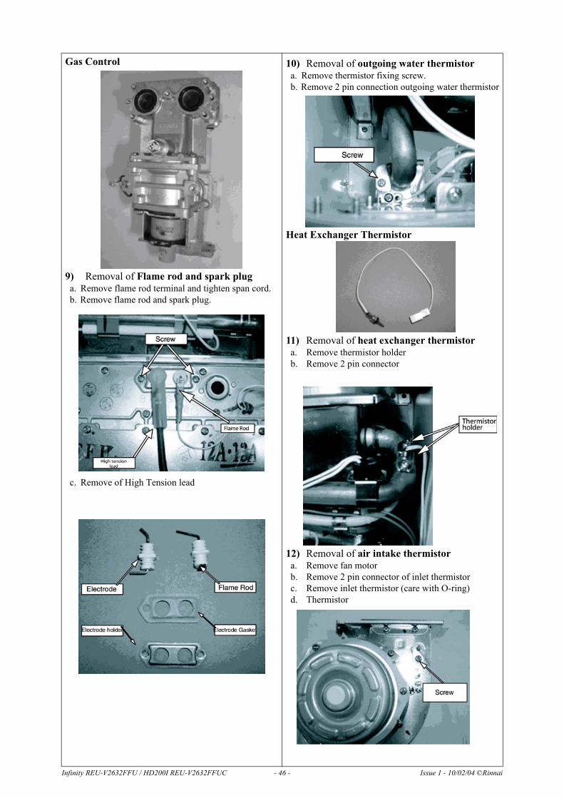
Gas Control
9) Removal of Flame rod and spark pluga. Remove flame rod terminal and tighten span cord.b. Remove flame rod and spark plug.
c. Remove of High Tension lead
10) Removal of outgoing water thermistora. Remove thermistor fixing screw.b. Remove 2 pin connection outgoing water thermistor
Heat Exchanger Thermistor
11) Removal of heat exchanger thermistora. Remove thermistor holderb. Remove 2 pin connector
12) Removal of air intake thermistora. Remove fan motorb. Remove 2 pin connector of inlet thermistorc. Remove inlet thermistor (care with O-ring)d. Thermistor
Infinity REU-V2632FFU / HD200I REU-V2632FFUC - 46 - Issue 1 - 10/02/04 ©Rinnai

13) Removal of Bypass Servoa. Remove fan motor (Refer to 14)b. Remove 3 pin connectorc. Remove 2 pin connectord. Remove 6 pin connector and 5 pin connectore. Remove bracket for water connection tube.
f. Removal of inlet water connection
g. Remove bypass servo and water flow servoh. Remove fitting screws of bypass servo
i. Flow sensor and water flow servo
14) Removal of Anti Frost Switcha. Remove 2 pin connection for anti frost switchb. Remove Anti Frost switch
c. Anti Frost switch
Infinity REU-V2632FFU / HD200I REU-V2632FFUC - 47 - Issue 1 - 10/02/04 ©Rinnai

15) Removal of Anti Frost heatera. Remove 2 pin connection of Anti Frost heaterb. Remove bracket of hot water connection.c. Remove Anti Frost heater.
16) Removal of the Fan Motora. Remove 4 pin connectorb. Remove 2 pin connector of solenoid valve.
c. Remove joint bracketd. Remove connection joint from the fan motore. Remove fan motor screw
f. Remove fan motor
Infinity REU-V2632FFU / HD200I REU-V2632FFUC - 48 - Issue 1 - 10/02/04 ©Rinnai

17) Removal of Heat Exchangera. Remove PCBb. Remove fan motorc. Remove 2 pin connector of thermal fused. Remove flame rod terminal of high tension corde. Remove anti frost heater switchf. Remove 2 pin connectorg. Remove 3 pin connectorh. Remove back pressure tubei. Remove air intake.
j. Remove fixing screw
k. Remove fixing screws of the heat exchanger unit
l. Remove heat exchanger screws
m. Remove Bypass tube
n. Pull out heat exchanger screws
o. Remove manifold and burner unit.p. Remove thermal fuse, over heat switch, sparker,
hex thermister and back pressure joint.
Infinity REU-V2632FFU / HD200I REU-V2632FFUC - 49 - Issue 1 - 10/02/04 ©Rinnai

Infinity REU-V2632FFU / HD200I REU-V2632FFUC - 50 - Issue 1 - 10/02/04 ©Rinnai
18) Removal of Thermal Fusea. Remove heat exchanger.b. Remove Thermal Fuse
After removal of thermal fuse fitting procedure is as follows:
Heat Exchanger Front
Heat Exchanger Left
Heat Exchanger Right
Heat Exchanger Rear

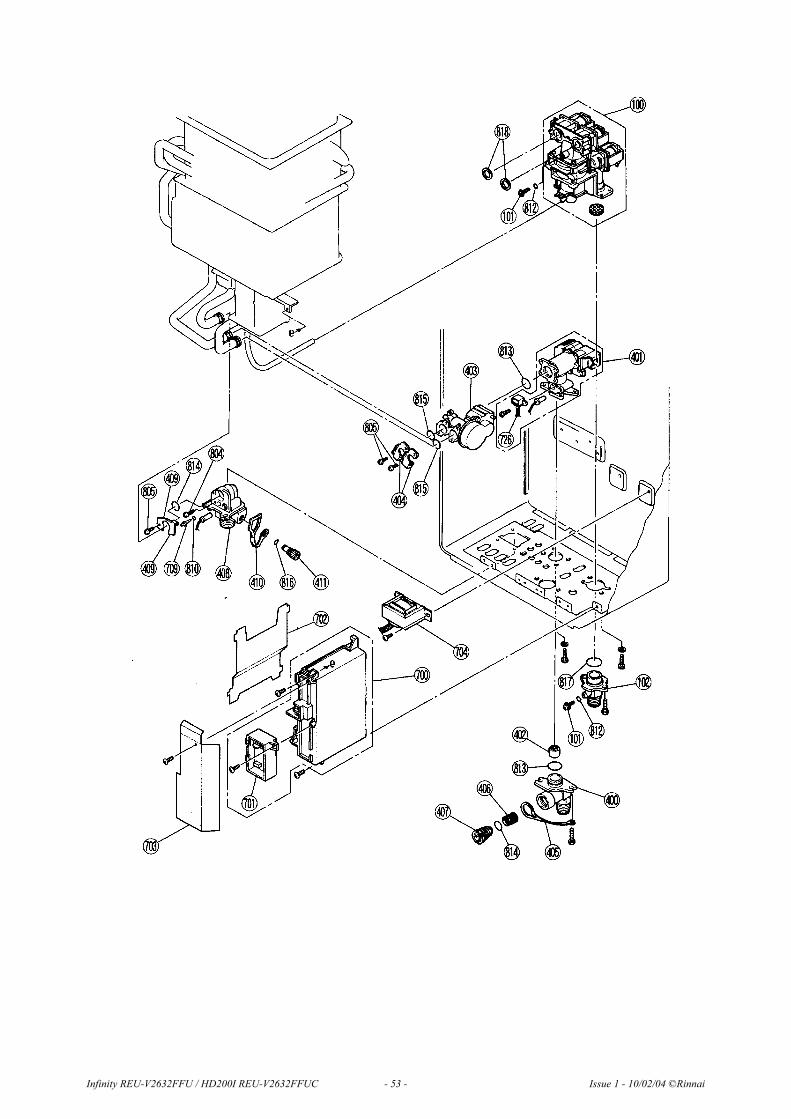
20. Exploded Diagram
Infinity REU-V2632FFU / HD200I REU-V2632FFUC - 51 - Issue 1 - 10/02/04 ©Rinnai

Infinity REU-V2632FFU / HD200I REU-V2632FFUC - 52 - Issue 1 - 10/02/04 ©Rinnai
Infinity REU-V2632FFU / HD200I REU-V2632FFUC - 53 - Issue 1 - 10/02/04 ©Rinnai

Infinity REU-V2632FFU / HD200I REU-V2632FFUC - 54 - Issue 1 - 10/02/04 ©Rinnai

21. Parts List
REU-V2632FFU-A REU-V2632FFUC-A
001 BODY Assy, Main - Wh U245-100-3 92092048 1
001 BODY Assy, Main - Sil U245-100-3 1
002 BRACKET - Mtg. U242-111-2 2
002 BRACKET - Mtg. U242-111-7 2
004 PANEL, Conn. Reinf. U245-120 1 1
005 SHIELD, Heat Ins. U245-107 1 1
006 PANEL, Fr - Wh U245-110-3-A 92092055 1
006 PANEL, Fr - Sil U245-110-5-B 92092493 1
007 SEALING, Fr Panel BU195-167 92086909 1 1
008 SEALING, B. Side AU105-113 92063361 1 1
009 SKIRT, Cable BU56-602-N 92073352 1 1
010 GASKET AU105-113 1 1
100 SOLENOID Valve Assy C36E-43-S 92092063 1 1
101 SCREW, Test Pt. Seal C10D-5 1 1
102 CONNECTION, Gas R3/4 CU195-211 92081587 1 1
103 BURNER UNIT Assy H73-110 92092212 1 1
104 BURNER CASE, Fr. plate CH51-209 1 1
105 BURNER CASE, Btm plate H73-112 1 1
106 GASKET, Burner Case BH51-218 1 1
107 BURNER, Assy B3A-1 16 16
108 BURNER CASE, Back plt CH51-221 1 1
109 DAMPER H73-115 1 1
110 MANIFOLD Assy (Prop.) U245-200-A 92092089 1 1
110 MANIFOLD Assy (NG) U245-200-D 92092550 1
111 SEALING, Comb AU155-207-2 1 1
112 SEALING LOWER, Comb CmbrH73-214 1 1
114 FRONT PLATE, Comb Cmbr U245-260 1 1
115 FRONT PLATE, Comb Cmbr U245-261 1 1
116 ELECTRODE H73-120 92086974 1 1
117 ELECTRODE FR AH41-216 92086982 1 1
118 GASKET, Electrode AH66-393 92086990 1 1
119 HOLDER, Electrode AH66-393 92087006 1 1
120 PACKING UPPER, Comb Cmbr U245-262 1 1
121 JOINT, Back Press. U242-312 1 1
122 TUBE - C, Wind Press. AU161-665-C 92071570 1 1
125 FAN MOTOR Assy U245-753 92092097 1 1
126 FAN CASING Assy U245 -555 1 1
Infinity REU-V2632FFU / HD200I REU-V2632FFUC - 55 - Issue 1 - 10/02/04 ©Rinnai

REU-V2632FFU-A REU-V2632FFUC-A
127 CONNECTION, Fan BH29-606 1 1
128 PACKING, Fan Conn. U245-750 1 1
129 FAN MOTOR U245-753 1 1
130 BELL MOUTH U245-558 1 1
131 HOLDER, Joint U245-566 1 1
135 DUCT, Air Intake U245-401 1 1
136 HOLDER, Joint U245-408 1 1
137 JOINT U245-409 1 1
138 CLIP, Joint U245-567 1 1
139 TERMINAL, Air Intake U245-410-2 1 1
140 FRAME, Flue Collector U245-434 1 1
141 HOLDER, Flue Collector U245-435 2 2
142 LID, Air Intake Term U245-419 1 1
145 CLOSURE, Heat Exch U245-690 92092105 1
145 CLOSURE, Heat Exch U245-690-C 1
400 CONNECTION 3/4, Inlet Water H73-501 92089044 1 1
401 SERVO, Water Flow M8E-6-6 / M8E-6-7 92092113 1 1
402 RECTIFIER M8D1-15 1 1
403 SERVO Assy, Bypass M6J-1-3 92092121 1
404 BRACKET AH69-310 2
405 STRAP, Plug H73-512 1 1
406 FILTER, Inlet Water H73-511 92083773 1 1
407 FILTER, Plug H73-510 1 1
408 CONNECTION 3/4, A U245-865-1 1 1
409 JOINT, Back Pressure U245-401 1 1
410 BRACKET, Holder AU162-1876 1 1
411 STRAP, Hot Water Outlet AU129-526 92081751 1 1
700 PCB Assy U245-770 92092139 1 1
701 SUB BOARD, Assy BU195-1643-2 92092147 1 1
702 COVER, PCB U245-774 1 1
703 COVER, EC BU168-707 1 1
704 TRANSFORMER Assy ET-282 92092154 1 1
705 MOUNTING PLATE, PCB Case U245-257 1 1
706 SPARKER EI-189 92092162 1 1
707 LEAD, High Tension BH38-710-240 92092253 1 1
708 SLEEVE, Electrode AU206-218 92087030 1 1
709 THERMISTOR BH45-650 92062322 2 2
710 HOLDING PLATE, Large CP-90172 92086388 1 1
711 MOUNT BKT, Fuse U217-676 5 5
Infinity REU-V2632FFU / HD200I REU-V2632FFUC - 56 - Issue 1 - 10/02/04 ©Rinnai

REU-V2632FFU-A REU-V2632FFUC-A
712 SWITCH, Low Temp. Sensor U242-511 92092170 1 1
713 HEATER Assy, A/Frost U245-775 92093293 1 1
714 HEATER, Valve U245-776 92092261 1 1
716 MOUNTING BRACKET, Htr CF29-742 92093301 2 2
717 MOUNTING BRACKET, Htr A AU111-653 92093319 - -
718 MOUNTING BRACKET, Htr AU100-721 92076123 1 1
719 THERMISTER, Inlet BH195-1630 1 1
720 POWER CORD CP-90491T 92089051 1 1
721 HARNESS, Fuse U245-603 92081900 1 1
722 HARNESS, 100V U245-885 1 1
723 HARNESS, Solenoid Valve U245-602 1 1
724 HARNESS, Sensor U245-603 1 1
725 FUSE Assy, Thermal U245-885 92092188 1 1
726 MR SENSOR Assy M8D1-10-4 92092279 1 1
800 BOLT ZIHD0510UK 8 8
801 SCREW, Small Truss ZFDB0408UK 4 4
801 SCREW, Small Truss ZHDC0408UK 1 1
802 WASHER AU33-184 3 3
803 SCREW CP-21478-412 3 3
804 SCREW, Thermister U217-449 1 1
805 SCREW, Small Pan ZAA0408UK 3 3
810 O-RING M10B-2-4 92062249 2 2
811 O-RING M10B-2-3 92071488 1 1
812 O-RING M10B 13-4 1 1
813 O-RING M10B-2-18 92071182 1 1
814 O-RING M10B-2-16 92062199 1 1
815 O-RING M10B-2-14 92062207 2 2
817 O-RING M10B-1-24 92062272 1 1
818 WASHER C36E1-6 2 2
888 CUSTOMER INSTR. U245-795 1 1
888 CUSTOMER INSTR. U246-796 1 1
889 INSTALLATION INSTR. U245-790 1 1
Infinity REU-V2632FFU / HD200I REU-V2632FFUC - 57 - Issue 1 - 10/02/04 ©Rinnai

Infinity REU-V2632FFU / HD200I REU-V2632FFUC - 58 - Issue 1 - 10/02/04 ©Rinnai
Notes
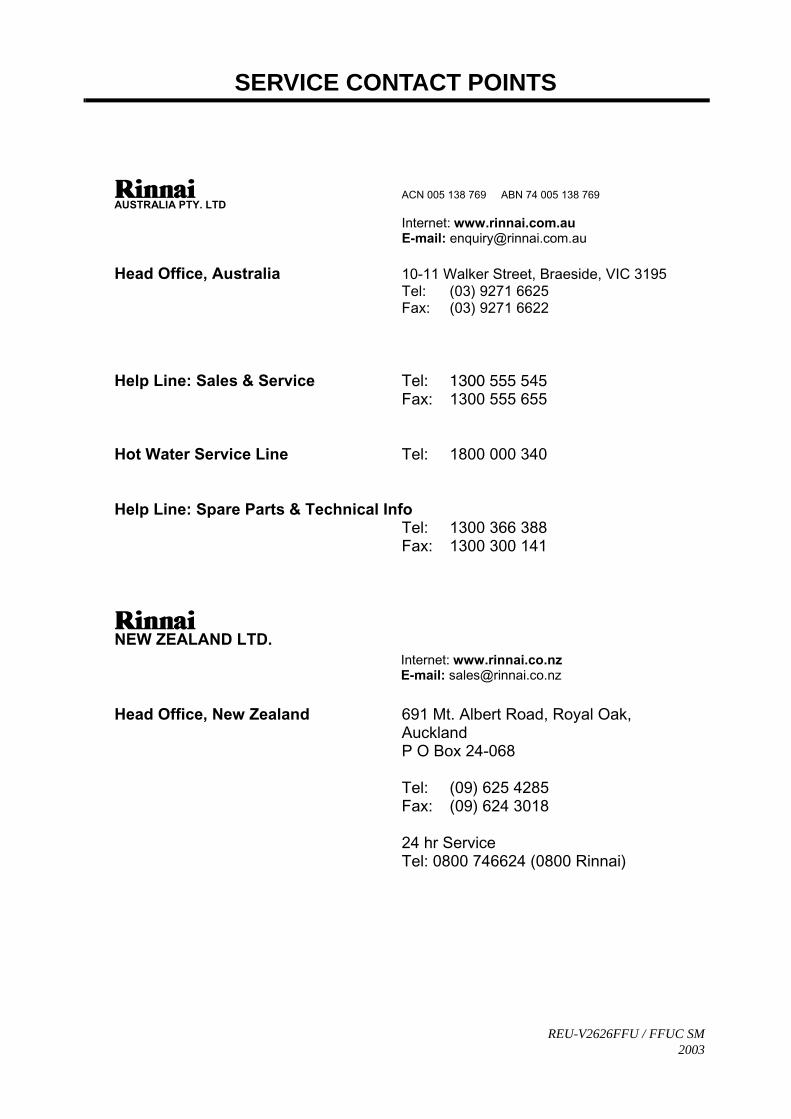
SERVICE CONTACT POINTS
REU-V2626FFU / FFUC SM2003
AUSTRALIA PTY. LTD ACN 005 138 769 ABN 74 005 138 769
Internet: www.rinnai.com.au E-mail: [email protected]
Head Office, Australia 10-11 Walker Street, Braeside, VIC 3195 Tel: (03) 9271 6625 Fax: (03) 9271 6622
Help Line: Sales & Service Tel: 1300 555 545 Fax: 1300 555 655
Hot Water Service Line Tel: 1800 000 340
Help Line: Spare Parts & Technical Info Tel: 1300 366 388 Fax: 1300 300 141
NEW ZEALAND LTD. Internet: www.rinnai.co.nz E-mail: [email protected]
Head Office, New Zealand 691 Mt. Albert Road, Royal Oak, Auckland P O Box 24-068
Tel: (09) 625 4285 Fax: (09) 624 3018
24 hr Service Tel: 0800 746624 (0800 Rinnai)


