
Improving Changeover Efficiency in
Opticap® XL Encapsulation Process
A Major Qualifying Project submitted to the faculty of
Worcester Polytechnic Institute
In partial fulfillment of the requirements for the Degree of Bachelor of Science
December 17, 2015
SUBMITTED BY:
Serhan Delareyna
Emily Doherty
Samantha Kwan
Nicolas Riart
SPONSOR:
MilliporeSigma
ADVISOR:
Andrew Trapp, Ph.D.

i
Abstract
This project studied MilliporeSigma’s changeover efficiency within the Opticap® XL
encapsulation process to alleviate throughput issues associated with increasing demand. Our
team conducted time and observational studies, together with stakeholder interviews, to identify
and prioritize improvement areas. We developed a production schedule optimization tool, Single
Minute Exchange of Dies analysis for changeover tasks, and conditions to streamline melt-check
procedures. We recommend our deliverables be implemented to improve changeover efficiency,
and estimate that 230 minutes can be saved in changeover time over two days.

ii
Acknowledgements
We would like to thank our sponsor, MilliporeSigma, for the opportunity to work with
their entire team for the duration of our project. Without their dedication and support, our project
would not have been possible. We would specifically like to acknowledge the following people
for their unwavering assistance and insight:
Justin Hocter, Production Manager, Project Liaison
David Plourde, Operations Manager
Scott McGillivray, Opticap® XL Schedule Planner
Opticap® XL Production Lead
Material Handler Lead
Quality Engineers
Additionally we express our sincere gratitude to the entire manufacturing team for their
willingness to share their knowledge on production and their ideas. Finally, we thank our project
advisor, Professor Andrew Trapp, Ph.D., for his continuous encouragement, guidance, and
support throughout the completion of our project.

iii
Authorship
This report was written equally by Serhan Delareyna, Emily Doherty, Samantha Kwan,
and Nicolas Riart. Sections of the report were initially drafted by an individual, however each
section was revised and edited in a combined group effort to comprise the final report. The
mathematical formulation of the optimization model was devised by Professor Andrew Trapp
and implemented in Excel and VBA as a team. A majority of coding for the model was
completed by Serhan Delareyna.

iv
Table of Contents Abstract ............................................................................................................................................ i
Acknowledgements ......................................................................................................................... ii
Authorship...................................................................................................................................... iii
1 Introduction ......................................................................................................................... 1
2 Background ......................................................................................................................... 3
2.1 EMD Millipore.................................................................................................................... 3
2.2 Opticap® XL ....................................................................................................................... 5
2.3 Encapsulation Process in MilliporeSigma’s Jaffrey Plant .................................................. 6
2.4 Changeover Time .............................................................................................................. 10
2.5 Time Studies ..................................................................................................................... 10
2.6 Current State: Changeover Process in XL1, XL2, and XL4 Production Lines .................11
2.7 Previous Project Work at MilliporeSigma ........................................................................ 12
2.8 Lean Manufacturing .......................................................................................................... 13
2.9 Modeling Tools & Optimization ....................................................................................... 15
3 Methodology ..................................................................................................................... 19
3.1 Identify Areas of Improvement ......................................................................................... 20
3.2 Evaluate & Prioritize Areas of Improvement .................................................................... 21
3.3 Develop Improvement Strategy ........................................................................................ 23
3.3.1 Optimization of Production Schedule ............................................................................... 23
3.3.2 Standardization of Changeover Tasks ............................................................................... 24
3.3.3 Redesign of Melt Check Procedures ................................................................................. 24
4 Results & Analysis ............................................................................................................ 26
4.1 Areas of Improvement ...................................................................................................... 26
4.1.1 Observations ..................................................................................................................... 27
v
4.1.2 Interviews .......................................................................................................................... 27
4.2 Evaluation & Prioritization ............................................................................................... 29
4.3 Improvement Strategy Deliverables ................................................................................. 31
4.3.1 Optimization of Production Schedule ............................................................................... 31
4.3.2 Standardization of Changeover Tasks ............................................................................... 39
4.3.3 Redesign Melt Check Procedures ..................................................................................... 41
5 Recommendations & Conclusions .................................................................................... 43
6 Reflections ........................................................................................................................ 46
References ..................................................................................................................................... 48
Appendix A: Production Lines Facility Layouts .......................................................................... 52
Appendix B: Operators Interview Questions ................................................................................ 54
Appendix C: Production Lead Interview Questions ..................................................................... 55
Appendix D: Material Handler Interview Questions .................................................................... 56
Appendix E: Data Collection Sheet .............................................................................................. 57
Appendix F: Task Turnover Chart ................................................................................................ 58
Appendix G: Melt Check Scenarios ............................................................................................. 60
Appendix H: Melt Check Data Collection Sheet .......................................................................... 62
Appendix I: VBA Code for the Production Schedule Optimization Tool ..................................... 63
Appendix J: Production Schedule Optimization Tool User Instructions ...................................... 82
Appendix K: SOP Proposal 1 ........................................................................................................ 84
Appendix L: SOP Proposal 2 ........................................................................................................ 85
Appendix M: SOP Proposal 3 ....................................................................................................... 86

vi
List of Figures Figure 1 Merck KGaA’s, Darmstadt, Germany Organizational Structure ..................................... 4
Figure 2 Tangential Flow Filtration Diagram ................................................................................. 5
Figure 3 Normal Flow Filtration ..................................................................................................... 5
Figure 4 Project Site Location ........................................................................................................ 7
Figure 5 Facility Layout of Production Line XL1 .......................................................................... 8
Figure 6 Encapsulation Process at MilliporeSigma ........................................................................ 9
Figure 7 Methodology Road Map ................................................................................................. 19
Figure 8 Our Areas of Improvements ........................................................................................... 26
Figure 9 Production Schedule Optimization Tool Interface ......................................................... 37
Figure 10 Production Schedule Optimization Tool Output Data .................................................. 38
Figure 11 Tooling Time Comparison ............................................................................................ 39
Figure 12 Facility Layout of Production XL2 .............................................................................. 52
Figure 13 Facility Layout of Production Line XL4 ...................................................................... 53

vii
List of Tables Table 1 Pharmaceutical Applications for Opticap® XL .................................................................. 6
Table 2 Lean Manufacturing Tools ............................................................................................... 14
Table 3 SMART Sample ............................................................................................................... 22
Table 4 Categorized Areas of Improvement ................................................................................. 29
Table 5 Our Team's SMART Analysis Results ............................................................................. 30
Table 6 Mr. Hocter's SMART Analysis Results ............................................................................ 30
Table 7 Code to Catalog Number Characteristics ......................................................................... 32
Table 8 Product Characteristics' Weight (Minutes) ....................................................................... 32
Table 9 Example Characteristic Influence .................................................................................... 33
Table 10 XL1 Production Schedule .............................................................................................. 33
Table 11 XL2 Production Schedule .............................................................................................. 34
Table 12 XL4 Production Schedule .............................................................................................. 34
Table 13 Sample Turnover Chart .................................................................................................. 40
Table 14 Impact Summary ............................................................................................................ 45

1
1 Introduction
Within the United States, the life sciences industry is one of the country’s largest markets
encompassing biotechnology, medical technology, and pharmaceuticals (Global -
Pharmaceuticals, Biotechnology & Life Sciences, 2012). Because this industry is steadily
growing and directly affects consumers, the Food and Drug Administration (FDA) oversees it
and mandates specific regulations. In addition to FDA regulations, economic and time factors are
considered when manufacturing and distributing health care products. Due to these regulations,
manufacturing can be disrupted and production times may be adversely affected. Bio-
manufacturing companies use extensive resources to properly prepare and install filter elements,
sterilize the production area and filter elements, and maintain the facility (Rios, 2003). This
consideration, in addition to the Affordable Care Act, which provides better health security by
expanding coverage, lowering healthcare costs, and enhancing the quality of care (Affordable
Care Act), has led to the need for innovation in the industry.
Life sciences companies have adopted single-use equipment into their manufacturing
process to help reduce the burden caused by FDA regulations during manufacturing. Significant
benefits to single-use equipment are the reduction in cross-contaminations, as well as faster,
more flexible product changeover (Eibl & Eibl, 2010). Additionally, disposable equipment has
improved process safety, environmentally-friendly cleaning and sterilization, and reduced time,
cost, and facility footprint (Eibl & Eibl, 2010). Furthermore, because single-use systems are
made from plastic, disposing in an environmentally-friendly manner can help alleviate any
detrimental impact to the environment (Olawuyi, 2013).
MilliporeSigma is a leading manufacturer of single-use filters for the life sciences and
beverage industries. These products are essential to MilliporeSigma's customer base as their
customers utilize these filters to separate "suspended particles from the fluid through a porous
material in which the fluid can pass while the suspended particles are retained" (“Filtration,”
2009). This process is otherwise known as filtration. MilliporeSigma’s Opticap® XL products,
one of MilliporeSigma’s top-selling filtration products, currently run at a very high level of
capacity utilization. Despite pending capacity upgrades planned for the second half of 2015,
utilization is anticipated to be above desired levels in 2016. Reduction in changeover time will
directly enhance asset availability and delay or even avoid future capital investment. We believe

2
that through simplified tooling and process optimization, changeovers and the need for technical
staff to accomplish them can be reduced.
The goal of this project is to reduce changeover frequency and complexity in the
Opticap® XL encapsulation process. The scope includes production scheduling and operational
procedures. In order to achieve the goals, our team set the following objectives:
1. Identify areas of improvement
2. Evaluate and prioritize the areas of improvement
3. Develop and potentially implement three improvement strategies
Our first area of improvement focused on the optimization of MilliporeSigma’s
production schedule in which the team delivered an optimization model to improve the sequence
of lots in the production schedule. Next we analyzed the standardization of changeover tasks in
which we delivered a standardized sequence of changeover tasks through Gantt charts and
standard operating procedures. Finally, we looked at redesigning the melt check procedures and
produced a set of procedures to be reviewed by the quality team at MilliporeSigma. We believe
the implementation of our deliverables will substantially improve the changeover frequency and
complexity in the Opticap® XL production lines at MilliporeSigma.
In continuation of this report, Chapter 2 presents background research concerning the
context of our project. Chapter 3 provides information on the methods that we utilized to achieve
our objectives. Chapter 4 presents the results and analysis of our methods that describe our
deliverables. Chapter 5 describes our conclusions, impact of our deliverables in reducing the
changeover time, and recommendations based on our findings. Lastly, Chapter 6 contains our
overall reflections on our work with MilliporeSigma and suggestions for future research.

3
2 Background
The background chapter begins with MilliporeSigma’s company overview and its role in
the bioscience industry with the production of filters. The following sections discuss the
Opticap® XL filter, its manufacturing process, and changeover procedure. In addition, this
chapter provides research on past projects related to MilliporeSigma’s Opticap® XL changeover
procedure, lean manufacturing, and modeling tools.
2.1 EMD Millipore
EMD Millipore, founded in 1954, is a billion-dollar company operating in the life
sciences industry. Acquired in 2010 by Merck KGaA, Darmstadt, Germany, EMD Millipore
became Merck KGaA’s, Darmstadt, Germany, life science tools division and produces over
60,000 different products. However, on September 22, 2014, Merck KGaA, Darmstadt, Germany
and Sigma Aldrich publicly announced their acquisition agreement (“Sigma-Aldrich
Shareholders Approve Merger With Merck,” 2014), which neared closing on November 10, 2015
(“Sigma-Aldrich and Merck KGaA, Darmstadt, Germany, Obtain EC Antitrust Approval and
Work Toward Closing Planned Acquisition,” 2015). With the acquisition of Sigma Aldrich,
Merck KGaA, Darmstadt, Germany has rebranded EMD Millipore as MilliporeSigma. Merck
KGaA, Darmstadt, Germanyand MilliporeSigma products are known worldwide for their quality
and performance in the life science industry. MilliporeSigma acts as a supplier to scientists,
engineers, and researchers, ensuring that all facets of the life science industry have access to their
products (“Our History,” 2015).
MilliporeSigma is divided into three business sectors (Figure 1): Bioscience, Lab
Solutions, and Process Solutions. The Bioscience division focuses on delivering products to the
academic and pharmaceutical environments. MilliporeSigma Lab Solutions’ goal is to ensure that
all products are cost effective and uphold their quality standards. The Lab Solutions’ products,
water purification systems, and microbiology testing solutions are used in laboratories among
various industries. Finally, the Process Solutions’ products are used by drug manufacturing
companies (“The Merck Group: Business Sectors and Businesses,” 2015). With these three
subdivisions, MilliporeSigma is able to help customers succeed in research, development, and
production.

4
Figure 1 Merck KGaA’s, Darmstadt, Germany Organizational Structure
Merck KGaA, Darmstadt, Germany and MilliporeSigma’s goal is to “deliver
entrepreneurial success through innovation” (“Mission Statement,” 2015). Worldwide,
MilliporeSigma has 28 manufacturing sites and 10,000 employees in 66 countries (“Our
History,” 2015). Their headquarters are located in Billerica, Massachusetts and the distribution
center is in Taunton, Massachusetts. The Jaffrey, New Hampshire site is considered a
Manufacturing Center of Excellence by MilliporeSigma, has more than 800 employees, and is
where our project took place (Hocter, 2015).
MilliporeSigma is an industry leader that includes competitors Pall Corporation and
General Electric Healthcare in the production of disposable or single-use filters (Hocter, 2015).
These capsule filters save customers time and money that is usually lost while assembling,
cleaning, and validating stainless steel housings. Every disposable filter produced by
MilliporeSigma must pass an integrity test to ensure the filters meet quality standards (“Opticap®
XL and XLT Disposable Capsule Filters with Milligard Media - Dairy,” 2015).
The two disposable filter types produced by MilliporeSigma are Tangential Flow
Filtration (TFF) and Normal Flow Filtration (NFF) filters. The differences between TFF and NFF
are related to how the solution travels and what the filter collects. In TFF (Figure 2), the solution
travels by the surface of the membrane filter where the difference in pressure pushes components
through the membrane pores. The remainder of the solution continues to flow through the
filtration process (General Electric Biosciences, 2014).
Merck KGaA, Darmstadt, Germany
Merck KGaA, Darmstadt, Germany in
North America
EMD Serono
MilliporeSigma
Bioscience
Lab Solutions
Process SolutionsEMD
Performance Materials
Merck KGaA, Darmstadt, Germany
International

5
Figure 2 Tangential Flow Filtration Diagram
On the other hand, during NFF (Figure 3) the solution travels perpendicular to the filter.
The membrane in this filtration retains all components that do not pass through the pores due to
the size of the components. Over time, the flow is reduced due to the residual build up in the
membranes and requires the NFF to be replaced (General Electric Biosciences, 2014). The
following sections will discuss the Opticap® XL’s primary applications, manufacturing process,
and MilliporeSigma’s current state of production.
Figure 3 Normal Flow Filtration
2.2 Opticap® XL
Opticap® XL is a NFF disposable capsule used in primary pharmaceutical applications
such as cell culture media, final aseptic fill of small volume parenteral, large volume parenteral,
plasma proteins, and serum. Table 1 provides a description of the pharmaceutical applications for
Opticap® XL.

6
Pharmaceutical Applications Description
Cell Culture Media Removes particles and colloidal contaminants without
impeding the flow of vital constituents
Buffer Filtration
Provides a means of rendering buffer solutions sterile by
creating a microbial barrier capable of trapping common
bacterial contaminants
Final Aseptic Fill of Small
Volume Parenteral
Increases the service life of downstream sterilizing
filters to remove colloidal and particulate contaminants
Large Volume Parenteral Increases the service life of downstream sterilizing
filters to remove colloidal and particulate contaminants
Plasma Proteins – Human
Albumin
Removes colloids, aggregated and non-product proteins,
lipids and particles before downstream purification
without holding back fractions of interest.
Serum
Removes colloids, aggregated and non-product proteins,
lipids and particles from serum before final sterilizing
filtration without holding back fractions of interest.
Table 1 Pharmaceutical Applications for Opticap® XL
(“Opticap® XL and XLT Disposable Capsule Filters with Milligard Media - Beer Processing,” n.d.)
The disposable feature of the Opticap® XL reduces time and exposure associated with
assembly, cleaning, and validation in comparison to stainless steel capsule filters. The Opticap®
XL is reliable in sterility and cleanliness; in effect it eliminates cross-contamination.
MilliporeSigma produces the Opticap® XL in compliance with ISO 9000 Quality Systems
Standard and is extensively tested for quality assurance throughout production (“Opticap® XL
and XLT Disposable Capsule Filters with Milligard Media - Beverage Processing,” 2015).
MilliporeSigma produces multiple types of Opticap® XL which differ in cartridge size, fitting
combinations, capsule housings, and membranes (“Opticap® XL and XLT Disposable Capsule
Filters with Milligard Media - Beverage Processing,” 2015). Additionally the product can differ
in sterilization grades which include autoclavable, gamma irradiated, and gamma compatible.
2.3 Encapsulation Process in MilliporeSigma’s Jaffrey Plant
Encapsulation is one of the final processes for MilliporeSigma’s Opticap® XL products
prior to becoming a final product. Encapsulation is the covering of a device to protect it from the
surrounding environment (“Potting & Encapsulation,” 2015). The encapsulation process is one

7
of the main functions of MilliporeSigma’s Jaffrey Plant (Figure 4, (“Jaffrey, NH Maps,” 2015)),
and is the main focus of this project.
Figure 4 Project Site Location
MilliporeSigma’s Jaffrey Plant dedicates three production lines for the encapsulation
process of Opticap® XL products, XL1, XL2, and XL4. The production lines operate five days a
week, three shifts per day, with an optional weekend shift depending on the need for production.

8
Figure 5 Facility Layout of Production Line XL1
Production lines XL1 (Figure 5) and XL2 (Appendix A: Production Lines Facility
Layouts) are similar in characteristics, as both lines include one bonder machine, one welder
machine, one tester machine, and one bagger machine. Production line XL4 (Appendix A:
Production Lines Facility Layouts), however, has two bonder machines, one welder machine,
two tester machines, and one bagger machine. Since the cycle time of the welder is half of the
other machines, this production line is added by MilliporeSigma to balance cycle times and
improve efficiency. This allows MilliporeSigma to run a higher volume of filters in the XL4
production line. The scope of our project starts from the transportation of the materials from the
warehouse to the encapsulation process, and the packaging process that follows the
encapsulation (Hocter, 2015).
9
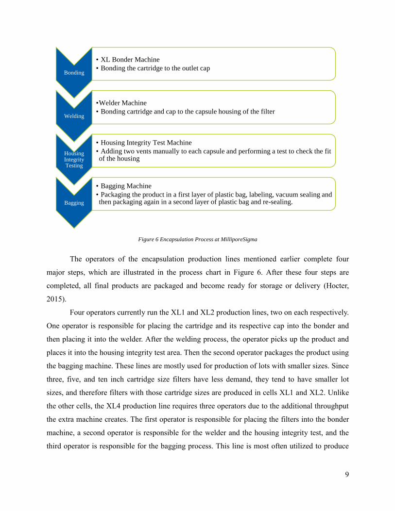
Figure 6 Encapsulation Process at MilliporeSigma
The operators of the encapsulation production lines mentioned earlier complete four
major steps, which are illustrated in the process chart in Figure 6. After these four steps are
completed, all final products are packaged and become ready for storage or delivery (Hocter,
2015).
Four operators currently run the XL1 and XL2 production lines, two on each respectively.
One operator is responsible for placing the cartridge and its respective cap into the bonder and
then placing it into the welder. After the welding process, the operator picks up the product and
places it into the housing integrity test area. Then the second operator packages the product using
the bagging machine. These lines are mostly used for production of lots with smaller sizes. Since
three, five, and ten inch cartridge size filters have less demand, they tend to have smaller lot
sizes, and therefore filters with those cartridge sizes are produced in cells XL1 and XL2. Unlike
the other cells, the XL4 production line requires three operators due to the additional throughput
the extra machine creates. The first operator is responsible for placing the filters into the bonder
machine, a second operator is responsible for the welder and the housing integrity test, and the
third operator is responsible for the bagging process. This line is most often utilized to produce
Bonding
• XL Bonder Machine
• Bonding the cartridge to the outlet cap
Welding
•Welder Machine
• Bonding cartridge and cap to the capsule housing of the filter
Housing Integrity Testing
• Housing Integrity Test Machine
• Adding two vents manually to each capsule and performing a test to check the fit of the housing
Bagging
• Bagging Machine
• Packaging the product in a first layer of plastic bag, labeling, vacuum sealing and then packaging again in a second layer of plastic bag and re-sealing.

10
two and four inch cartridge sized products, because it can handle the larger demand and lot sizes
for these filters (Jaffrey Facility Observations, 9/10/2015).
The bonders have an average machine cycle time of one minute and the welder has an
average cycle time of thirty seconds. These cycle times are standard and do not include the
manual work done by the operators of inserting a piece in the machine and removing it. The
housing integrity test also has a cycle time of one minute.
The processes mentioned above are for a line that is assumed to be running and for a
single type of product. However, in a typical day there are a variety of Opticap® XL products
going through the same line, requiring changeovers. Changeovers are performed in between the
production of different batches and requires significant time to ensure production for the next
batch to be performed correctly.
2.4 Changeover Time
Changeover time, also known as setup time, is an essential concept in every production
process that features changing materials, dyes, and machine recalibration (etc.). After the
production of a product is completed, a sequence of changeover activities is performed on a
machine prior to starting the production of another batch. During these activities, the machine
stands idle. Hence, reducing changeover time is necessary to increase productivity of a machine,
especially in production lines with small batch or lot sizes that lead to a large number of
changeovers (Singh & Khanduja, 2010).
As plants are unable to dedicate a production line to a single product type, changeovers
are inevitable for flexible production. Changeovers require basic work such as paperwork,
cleaning, and tooling modifications that need to be performed depending on the product type and
its production system constraints. However, non-value added activities that increase the duration
of changeover times are performed in actual practice.
2.5 Time Studies
A variety of methods may be used to further understand a process’s complexities and find
possible ways for improvement. A time study is a method that encompasses both objectives. A
time study is a “systematic observation, analysis, and measurement of the separate steps in the
performance of a specific job for the purpose of establishing a standard time for each
performance, improving procedures, and increasing productivity” (“Time and Motion Study,”

11
2015). It can highlight possible areas to improve based on the time the process takes, as well as
record improvements. Conducting time studies includes several steps. The first is the preparation
process that includes knowing the purpose for the time study, understanding the process being
measured, measuring its components in a representative time period, and gathering a good
sample size for reliable results (“Preparing to Measure Process Work with a Time Study,” 2015).
The second step involves choosing a process and the respective operator to observe. Next the
researcher would devise a data collection sheet. Lastly, the researcher observes the process and
collect times from the start to finish. Using time studies, observers can compare the baseline data
to the data resulting from the improved solutions (“Industrial Engineering and the Engineering
Digest,” 1915).
2.6 Current State: Changeover Process in XL1, XL2, and XL4 Production Lines
Specifically for the Opticap® XL products, changeovers are performed by the operator
and involve several steps, including changing parts to fit a specific capsule or cartridge size.
These steps are dictated by standard operating procedures (SOPs), which specify tasks to execute
in order to complete the changeover process. However, the SOPs do not include the order in
which to complete the tasks. The changeover tasks include operations both before and after
running a lot.
Before running a specific lot of filters, the first step is to check the work order
information. During this process the operator counts the number of cartridges and also checks if
the cartridges’ lot number matches with the number on the batch record, and the correct number
of labels have been provided. This allows operators to plan what changeover is needed in order
to start production. Each machine in the encapsulation process has specific SOPs.
For bonding, the bonder machine secures the parts in place with the help of inserts and
cartridge spacers. This step is completed by attaching the cartridge to the cap. These parts are
interchangeable based on the specific cartridge size. During the changeover, the inserts, located
in the upper nest, are used for two and four inch cartridges, while three, five, and ten inch
cartridges do not need the upper nest inserts. The lower nest of the machine, however, does not
need any adjustments. For all the cartridge sizes except the ten-inch, the changeover process
requires operators to switch out spacers based on the specific cartridge size (“Opticap® XL
Cartridge Bonder - SOP,” n.d.). After the bonder is set up for the next batch, the operator uses

12
scrap parts to perform the bubble and burst tests, which confirm the strength and integrity of the
parts, respectively (“Opticap® Bubble and Burst Tester (Melt Sample) - SOP,” n.d.).
The changeover process for the welder, however, involves the change of the top plate and
bottom nests. Because the welder is bonding the element created by the bonder to a housing
capsule, each nest requires a specific fixture plate based on capsule size. There are three pairs of
fixture plates, one for two and four inch, three and five inch, and ten inch capsules. The plates
are changed using a torque wrench set at a designated value. The setting of the wrench must be
checked for accuracy in between each shift and lot (“Opticap® XL Housing Weld - SOP,” n.d.).
For the housing integrity tester, the machine’s air pressure setting and fixtures are
changed based on the capsule’s size. Because each product is of different sizes, the amount of air
that needs to go through the product to test for integrity directly increases as size increases.
The cartridge counting, mentioned previously, can be done while the testing occurs, or if
there is a mechanic failure and production stops. There is no standard procedure established for
when it will be done. The testing process is performed again if the machine test fails and usable
parts from the batch are needed to perform another test. Once machines pass the quality test,
operators must complete the corresponding paperwork. The operator must transcribe the serial
number of the lot, his or her signature, and the date for each individual product in the lot; this
process allows MilliporeSigma to trace their products back to the specific lot and date in case
defects are reported.
After the paperwork is complete, the operators run the lot for the encapsulation process.
When the lot is complete, the changeover tasks that happen upon the completion of a lot are
performed. These tasks include replacing the missing parts, filling out the line closing
paperwork, sending samples for quality assurance, and cleaning the workstation before the next
work order. Operators sanitize the entire workstation (machines, bins, tables) with provided
disinfectant wipes. After sanitation is complete, the cycle starts from the beginning with
checking the accuracy of the next lot (Hocter, 2015).
2.7 Previous Project Work at MilliporeSigma
In 2013, a team of Worcester Polytechnic Institute (WPI) industrial engineering students
analyzed MilliporeSigma’s facility to improve the workflow and output of the Opticap® XL filter
encapsulation process (Chevis, Ortiz, & Vallenilla, 2014). The team’s objectives were to: “(1)
gain an in-depth understanding of the Opticap® XL encapsulation lines, (2) comprehend the

13
current state of production scheduling of the Opticap® XL encapsulation lines, (3) collect data on
the current state of the changeover process through time studies, (4) build a discrete-event
simulation (DES) model of the current process, (5) determine the impact of dedicating lines to
product characteristics by conducting scenarios analysis in the DES model, (6) analyze the
results from the different scenarios and provide recommendations regarding line dedication”
(Chevis et al., 2014).
By working towards these objectives the team was able to understand the current state of
the facility and develop an accurate representation of the environment using simulation. The
team used their simulation model to test different scenarios of line dedication to find the most
beneficial solution for MilliporeSigma. Through simulation, the team found that by dedicating
production lines by filter size, the total changeover time and cycle time improved significantly
(Chevis et al., 2014). The team recommended that production lines should be dedicated by filter
size, specifically having 2” and 4”, 3” and 5”, and 10” filters produced on production lines XL4,
XL1, XL2 respectively (Chevis et al., 2014).
After the completion of the 2013 project, MilliporeSigma took the team’s findings under
consideration. Currently, MilliporeSigma is dedicating the production lines by filter size which
has improved the current state of the facility. However as demand increases by 20-30% per year
for biopharmaceutical products, MilliporeSigma still faces the challenge to keep up with
demand. Because lot sizes can range from tens to hundreds of units, the frequency of
changeovers can be high and rather unpredictable (Hocter, 2015). Since the Jaffrey plant is 24-
hour facility and management needs to deal with problems related to production, the WPI team
assumed the role of helping MilliporeSigma in devising methods to further reduce the
changeover time in Opticap® XL production line. In the next section we will discuss the lean
methods we researched to reduce the changeover time.
2.8 Lean Manufacturing
Our team researched lean manufacturing tools that can help reduce the complexity in the
Opticap® XL changeover process, as lean manufacturing’s goal is to eliminate waste from
processes (Womack & Jones, 2010). Waste is everything in the process that does not add value to
the customer (“What is Lean?,” 2015). Amongst the established lean manufacturing tools, our
team pre-selected tools that may be more applicable for our purposes. Table 2 below describes

14
the lean manufacturing tools and presents potential applications for the Opticap® XL changeover
process.
Lean
Manufacturing
Tools
Description Potential Application
1 5s
Organizes the work area by
following five progressive
steps: Sort, Set in Order, Shine,
Standardize, and Sustain
Improve the organization of the
production line work area (Gomes,
Lopes, & de Carvalho, 2013)
2 Bottleneck
Analysis
Improves the process
performance by identifying the
step(s) of the process that
delays the throughput
Find the changeover bottleneck and
focus on it to improve its performance
(Vorne Industries Inc, 2013)
3 Just in Time
Pulls the parts instead of
pushing throughout the
production process
Reduce the level of inventory and
improve flow of materials (Voehl,
Harrington, Mignosa, & Charron,
2014)
4 Muda
(Waste)
Identifies the waste in the
process
Eliminate Muda and reduce the
duration of the changeover process
(Voehl et al., 2014)
5 Poka Yoke
Error-proofs design into the
production process
Correct common defects in the process
(Vinod, Devadasan, Sunil, & Thilak,
2015)
6 Root Cause
Analysis
Resolves the root problem
instead of treating early
symptoms
Eliminate a common defect that adds
waste to the changeover process (Vorne
Industries Inc, 2013)
7
Single
Minute
Exchange
of Die
Reduces changeover time by
converting processes performed
while machines are idle to
when machines are running
Reduce the changeover time by
modifying the changeover procedures
(Voehl et al., 2014)
8 Six Big
Losses
Provides a framework of most
common causes of waste:
breakdowns, set up, small
stops, reduced speed, startup
rejects, production rejects
Organize the identified wastes by
creating a framework of the six big
losses (Vorne Industries Inc, 2013)
9 Standard
Work
Documents steps of a procedure
to standardize best practices
Document the identified best practices
to ensure a well-done changeover
process (Vorne Industries Inc, 2013)
Table 2 Lean Manufacturing Tools

15
Singe Minute Exchange of Dies
Among the pre-selected lean manufacturing tools we considered implementing to fulfill
our project’s objectives, we further investigated tool ID 7, Single Minute Exchange of Dies
(SMED), since it is directly related to changeover processes. SMED is a system for reducing
equipment changeover times (Vorne Industries Inc, 2013). This system divides the changeover
process into each of its elements, sub-processes, and analyzes these elements in detail to see if
they can be eliminated, moved, simplified, and/or streamlined.
To analyze the changeover processes, the first step is to categorize processes as internal
or external activities. Internal activities can only be performed while the machine is shut down,
whereas external activities can be performed without shutting down the machine. The activities
that are categorized as external should be performed while the machine is running to prevent any
unnecessary machine downtime. Since the external activities can be performed while the
machine is running, the next step is to review the remaining internal activities and question how
they can be converted to external activities. The third step is to review all the remaining internal
activities to streamline and simplify. At this step, the changeover activities are simplified,
sequenced, and distributed to the workers in the way that maximizes efficiency. Once this step is
complete, the final step is to create standard operating procedures to sustain the new reduced
changeover time and start the cycle again periodically to seek continuous improvement
opportunities. While Lean Manufacturing tools can help improve processes, oftentimes problems
are too complex and need to be modeled to represent reality. The next section will discuss why
mathematical modeling is an important tool and how it can be utilized to optimize processes.
2.9 Modeling Tools & Optimization
Understanding and analyzing a given real-world scenario can be difficult, as physically
conducting a study is costly and time consuming (Chevis et al., 2014). To accurately portray a
situation, models can be used to mathematically represent reality. Through modeling, one can
test, modify, and predict the effects of a variety of different scenarios without having to
physically alter the environment. Another benefit includes the ability to learn from these
scenarios. For example, if the results of a model show negative consequences, then the
researcher could identify areas to modify in order to obtain the desired output. However, models
are limited by their inability to perfectly portray all aspects of the problem, and by the input
information due to the different levels of complexity each problem entails. A model’s complexity

16
increases as a practitioner attempts to represent every aspect of the real world problem. Because
it is often impossible to display every aspect of the problem, simplified models of the same
situation are made using assumptions and approximations (Sarker & Newton, 2007). Although
models create opportunities for companies to continuously improve and test new practices,
models often have inherent limitations, and the results should be carefully analyzed.
One way models are utilized is through optimization, “an act, process or methodology of
making something as fully perfect, functional or effective as possible” (“Optimization,” 2015).
An optimization model consists of three main components: decision variables, an objective
function, and constraints. Decision variables are the aspects of the problem that are changed to
result in different types of outcomes for the model. The numbers of units to produce at a specific
manufacturing center or which location would be best to build a warehouse are examples of
decision variables. Decision variables are essential as the values assigned to these variables
provide an optimal solution for the given problem (Sarker & Newton, 2007). The objective
function of a model drives the solution of a problem by providing a goal or objective to be
reached. The objective function looks to either minimize or maximize some metric related to the
problem. In manufacturing problems, objective functions are commonly trying to maximize
profits, minimize costs, or minimize makespan. Additionally, constraints represent the limitations
or restrictions stated in the problem. Constraints are necessary to accurately represent a given
scenario. The hours in a workday or the number of available workers during a shift would be
examples of constraints. By combining variables, an objective function, and constraints, a
realistic representation of a real-world scenario can be created.
Through optimization an optimal solution can be reached given that the associated model
accurately represents the problem. It can be utilized in a wide variety of disciplines such as
engineering, mathematics, economics, and administration. Additionally optimization can be
applied to forecasting, budgeting, process control, and production scheduling. In the context of
MilliporeSigma, an optimization problem may seek to minimize the number of the changeover
activities performed by choosing an improved sequence of materials, as indicated by the decision
variables, therefore reducing the complexity of the changeover process.
Optimization problems can range in size based on the number of decision variables and
constraints in the model. Optimization also varies in complexity with respect to the types of
equations, variables, and whether uncertainty is included. Some classic optimization problems

17
include the traveling salesman problem, vehicle routing, knapsack, facility location and layout,
and production planning and scheduling. Each type of optimization problem has specific
attributes. For example in a travelling salesman problem, the model’s objective is to find the
minimal length tour that passes through all locations and returns to the origin.
Scheduling
Scheduling is a domain that has seen many benefits from optimization. With scheduling,
planners focus on the number of resources available and the tasks that need to be completed.
Resources differ based on the problem, however they can be machines, production lines,
personnel, or tools. Tasks can also differ from operations in a process to stages in a project.
Machine scheduling can optimize one or several different criteria (Pinedo, 2012). Because
scheduling is dynamic, it incorporates external information such as utilization of the
manufacturing center, material inventory, and number of customer orders (Framinan, Leisten, &
Garcia, 2014). As situations arise where production must stop or be delayed, rescheduling or
rearrangement of the original schedule to adapt to changes occurs.
Through scheduling, companies are able to have detailed information on not only what is
in production, but also provide information on what material needs to be restocked, when
customers should expect their order, and predict future orders. Although scheduling helps
determine what should be produced when, it is not exact. As information is revealed closer to the
actual date of production, for example in terms of material required, schedules may change and
become more detailed. Thus schedules are only as detailed as the information provided. Some
objectives for scheduling problems include minimizing the total schedule duration, total
weighted flow time, number of tardy jobs, or weighted earliness and tardiness. Because of the
wide range of criteria scheduling models can address, there are a variety of scheduling problems.
Some of the problems include job shop, flow shop, single machine, and identical machines in
parallel (Pinedo, 2012).
Traveling Salesman Problem
Another kind of optimization problem is the traveling salesman problem, which aims to
find the shortest route or tour for a travelling salesman to visit all the cities on a list and return
back to the starting point (Applegate, Bixby, & Chvatal, 2011). The distance in which these

18
problems try to minimize depends on the order of the route. Traveling Salesman Problems (TSP)
are “typically hard combinatorial optimization problems” (Gutin & Punnen, 2002) which can be
difficult to solve due to their intractability. Despite these difficulties, TSPs are popular because
they can be easily understood. A travelling salesman problem consists of a graph that includes
locations to be visited, as well as inter-distances between locations. (Gutin & Punnen, 2002).
The variations in TSPs consist of either quadratic or linear permutation representation.
Quadratic permutation representation consists of sequencing problems, while linear permutation
representation focuses on cyclic or binary linear programming (Gutin & Punnen, 2002). TSPs
can be applied to a variety of disciplines such as computer science, operations research, genetics,
and electronics. Some surprising applications where Traveling Salesman Problems can be found
include machine scheduling, cellular manufacturing, VLSI chip design, and frequency
assignment problems. The formulation of these problems, however, can differ from a traditional
Traveling Salesman Problem. Some Traveling Salesman Problems seek to maximize the total
cost or distance of the tour, while other incorporate multiple salesmen.
A reason why Traveling Salesman Problems are difficult to solve is due to the number of
constraints needed to accurately represent the problem in the model. Constraints limit the model
from performing specific evaluations. For example in a TSP a constraint is to have the salesman
visit each location once and ensure that the salesman does not return to a location previously
visited. Problems that can arise in a TSP are subtours, which are addressed by subtour
elimination constraints. Subtour elimination constraints add additional limitations within the
model to ensure subtours do not exist. A common subtour elimination constraint is a Miller
Tucker-Zemlin (MTZ) constraint. MTZ constraints allow flexibility in the assignment of a set
location (Gutin & Punnen, 2002). However, MTZ constraints also “produce a weak linear
programming relaxation” (Sherali & Driscoll, 2002).

19
3 Methodology
The goal of our project was to reduce changeover frequency and complexity in the
Opticap® XL encapsulation process. Our team achieved this goal by completing the following
objectives:
1. Identify the areas of improvement in the changeover procedure
2. Evaluate and prioritize areas of improvement
3. Develop and potentially implement three improvement strategies
Our team learned about the changeover procedure by visiting the MilliporeSigma Jaffrey,
New Hampshire facility on a weekly basis from September 2015 to December 2015. We were
introduced to the project and supervised by our project liaison, Justin Hocter who is the
Production Manager responsible for overseeing the Opticap® XL as well as other products.
During our weekly visits our team collected information from observations, data collection, and
initial interviews with the operators and production leads. Next, we analyzed our findings to
identify the areas of improvement in the changeover process to then evaluate and prioritize our
improvement strategies. Finally, our team targeted three areas of improvement that resulted in a
strategy to reduce changeover frequency and complexity for the Opticap® XL encapsulation
process. Figure 7 presents the methodology road map.
Figure 7 Methodology Road Map
Identify • Data Collection
• Interviews
• Observations
Evaluate & Prioritize
• Weighted Average Table
• Areas of Improvement
Develop & Implement
• Strategy to reduce changeover complexity and frequency

20
3.1 Identify Areas of Improvement
In order to develop strategies to reduce changeover complexity, our team observed the
encapsulation and changeover processes to learn MilliporeSigma’s operations and how the
Opticap® XL products are produced. During our observations, our intent was to learn about the
bottlenecks in the process. The team gained an understanding of the encapsulation process for
Opticap® XL products by visiting the Jaffrey plant, observing production lines, and interviewing
the operators and other stakeholders in the process.
Site visits and observations
During our site visits, our team sought to observe the production lines and learn
information about all of the processes that directly or indirectly affect the changeover process.
We took notes and documented how the operators in the production lines performed the
processes. Through our observations, we hoped to gain an unbiased opinion on what the
bottlenecks were in the system. We also used the initial observations to identify stakeholders in
the process that we could interview to gain further insight on the areas that need improvement.
Interviews
The main purpose of the interviews was to understand the operators’ perspective on the
tasks they perform that directly or indirectly affect the changeover process. Our team interviewed
operators on the XL production lines to understand the encapsulation and changeover processes.
We also interviewed the production lead, the material handler, and production planner. Through
these interviews, we sought to learn about the overall process at MilliporeSigma and gain insight
into where we might make the most impact.
In order to understand their processes, we interviewed the operators that perform the
changeover tasks in the production lines. We asked questions (Appendix B: Operators Interview
Questions) about the tasks that they perform, what they perceived to be the biggest difficulties
during the changeover process, and the step that takes the most time. We also interviewed the
production lead of the shift that we were observing. The production lead has the duty of
supervising the cells and creating the daily schedules for the production lines. With this interview
we sought to understand how lots are presented to associates and identify the possible areas of

21
improvement with regards to scheduling that would simplify the tooling during the changeover
process. Because we wanted to encompass additional perspectives on the most difficult
changeover task, we acquired the supervisor’s opinion and observations of any variations
between shifts and operators. This information would indicate whether MilliporeSigma’s
processes should be more standardized. The full list of interview questions with the production
lead can be found in Appendix C: Production Lead Interview Questions.
To identify whether altering the way the materials are delivered could have an effect on
the changeover time, we interviewed the Material Handler. As counting material is included in
the changeover time, we asked the Material Handler’s perspective on the efficiency of using
alternative delivery methods for cartridges, caps, and housings such as bins with designated
space for each unit. Because counting is a non-value added activity, we looked into identifying
any areas of improvement with material handling that would have an indirect effect of
minimizing or eliminating the need for counting during a changeover process. The full set of
interview questions can be found in (Appendix D: Material Handler Interview Questions).
We also had an informational interview with the Production Planner, who prepares the
lots to be completed and presents them to the Production Lead. During this interview we sought
to understand the Production Planner’s methodology of preparing daily lots for production and
whether changeover complexity is taken into account. We wanted to identify if improving
communication between the planner and lead would have a significant impact in the changeover
process.
Through the site visits, observations and interviews, we were able to understand the
encapsulation and changeover process at MilliporeSigma. From this, we identified and analyzed
the areas for improvement and determined the difficulties the employees have during these
processes.
3.2 Evaluate & Prioritize Areas of Improvement
Through site visits, observational studies, and interviews, we identified twelve areas of
improvement, which we evaluated and prioritized. We evaluated these improvement areas by
thoroughly understanding the intricacies of each, how each would affect the changeover process,
and what the improvement would entail. Through this evaluation, we classified the twelve
improvement areas into three categories: production scheduling, operational procedures, and

22
presentation of materials. Once each improvement area was categorized, we prioritized all of
them in order to narrow our focus on the areas with highest impact.
We strategically prioritized the areas using simple multi-attribute ranking technique
(SMART). SMART is an analysis technique used to help decision makers make a provisional
decision through an eight stage process (Goodwin & Wright, 2009). First, we identified the
decision maker and the different alternatives or areas of improvements. Next, we derived three
attributes in which to compare each improvement area. The alternatives and attributes were
arranged into a table. A sample table (Table 3) depicts a generic table for which our SMART
analysis was performed.
Alternatives Attribute 1 Attribute 2 Attribute 3
Table 3 SMART Sample
We documented our relative scores for each area of improvement given the attribute in
the table. The scores were based on a one-to-five scale with one being poor and five being very
good for each criterion. Next we assigned weights to each attribute using a one-to-three scale
with one being the least important and three being the most important. The weights assigned for
the attributes represent how much the specific attribute affects our decision.
Given our scores and assigned weights, we performed a weighted sum. Through a
weighted sum we were able to reflect the importance of each attribute on its respective score by
multiplying the two values. After each weight score was derived, the scores for each attribute per
alternative were summed to create an overall score. The overall scores were then ordered from
highest to lowest in the table. This ordering provided our list of areas of improvements that we
should prioritize first.
After our prioritization, we presented all twelve ideas to our liaison, Mr. Hocter. We
asked Mr. Hocter to perform his own analysis to determine which improvement areas were of
higher priority for MilliporeSigma. In an open discussion, we compared the results of both
analyses to find commonalities and the most important ideas. Through the evaluation and
prioritization of the areas of improvements, we determined three main ideas to concentrate on to
reduce the changeover frequency and complexity. From these ideas, we developed improvement
strategies to potentially implement within MilliporeSigma’s Opticap® XL production lines.

23
3.3 Develop Improvement Strategy
After we evaluated and analyzed our areas of improvement, our team worked on
developing the improvement strategies. The following three improvement strategies were
developed and presented to MilliporeSigma for potential implementation; optimization of
production schedule, standardization of changeover process, and redesign of melt check
procedures. This section further describes how each improvement strategy was developed.
3.3.1 Optimization of Production Schedule
Our team first identified scheduling lots as an area of improvement from our initial
meeting with the Opticap® XL Production Planner, Scott McGillivray on October 5, 2015. After
our project team and MilliporeSigma liaisons agreed upon exploring this area of improvement,
we requested work order data to further investigate potential improvements. Mr. Hocter provided
our team with the work order details from January 2014 to December 2015 in a Microsoft Excel
spreadsheet file. Next, our team analyzed the data to better understand the components that
together make up a work order and used the standard operating procedures as an aid to ensure we
were analyzing the correct components throughout our analysis. We used Microsoft Excel to
analyze the data that included the lot code with the Excel MID function that returns the
characters from the middle of a text string, given a starting position and length. This allowed us
an efficient way to break down the individual work orders by material type, cartridge size, inlet
and outlets.
Our team then arranged a second meeting with Mr. Hocter and Mr. McGillivray to clarify
uncertainties. We asked about potential constraints related to the number of days a work order is
visible to the planner. From our background research found in Section 2.9, we identified that a
Traveling Salesman Problem model would be the right framework. Knowing this information,
our team followed optimization-modeling procedures of defining variables, setting constraints,
and developing an objective function before framing the model in Microsoft Excel. Lastly, our
team implemented the model in Microsoft Excel using VBA and OpenSolver to deliver a user-
friendly tool for MilliporeSigma to run for any given number of work orders to schedule a
production plan that minimizes the amount of changeover time.

24
3.3.2 Standardization of Changeover Tasks
For our team to successfully achieve the goal of standardizing the processes involved in
the changeover process, we interviewed operators, conducted time studies, implemented the
Single Minute Exchange of Dies (SMED) methodology, and compiled a list of best practices for
the operators throughout the changeover process. First, we interviewed the operators that
perform the changeover tasks in the production lines to identify similarities and differences in the
practices in which changeovers were performed. Next we compared the similarities and
differences to identify best practices to perform changeovers more effectively. Second, we
conducted time studies during our site visits at MilliporeSigma to gain a quantitative
understanding of bottlenecks in the encapsulation and changeover process. During these time
studies, we recorded the process time for each step in the process as well as the steps during the
changeover process. Our data collection sheets can be found in Appendix E: Data Collection
Sheet. These time studies gave us a quantitative answer to what the bottleneck was and an
understanding of the variability between operators. We conducted time studies on different lines
to determine whether there was variability between the production lines and operators.
Next, we used the SMED turnover chart to better organize the changeover tasks and to
reduce the changeover times. The completed turnover chart can be found in Appendix F: Task
Turnover Chart. We identified the changeover tasks and determined if they were completed while
the machines were running (external) or while the machines were not in production (internal).
We used the data from our time studies to fill in this chart with the appropriate time for each task.
Finally, we discussed with operators which tasks could be completed externally instead of
internally. This information helped us complete the standardized changeover process and
understand if there were any best practices that the team could recommend for the changeover
process.
Finally, the team created a list of best practices to standardize the changeover processes.
The team studied the SOPs and used the results of the SMED turnover chart, the interviews, and
time studies to ensure all tasks were listed and the recommendations were feasible.
3.3.3 Redesign of Melt Check Procedures
To understand the importance of melt checks and understand the areas of improvement,
the team interviewed operators and quality engineers, created and implemented a data tracking
document, and developed a new procedure for determining the frequency of melt checks.

25
The team interviewed the operators on the production line to understand how and when
the melt checks were completed. We analyzed this information and determined the melt check
was a bottleneck in the changeover process. Through our discussions with the operators and Mr.
Hocter, we brainstormed a list of possible scenarios in which melt checks would be completed,
found in Appendix G: Melt Check Scenarios. We presented this material to the Quality
Engineers. In this meeting, we received their feedback and determined more data is necessary
before the Quality Engineers could ensure that reducing the number of melt checks would not
decrease the quality of the products.
From this information, the team created a data collection form to be filled out by the
operators to understand how often the melt checks fail. This form was put in the production
process for two weeks and the operators recorded their data on the sheet provided by the team. A
sample of a completed data collection log can found in Appendix H: Melt Check Data Collection
Sheet. Next, the team analyzed the results of the data collection sheet in order to present findings
to the quality engineers.
Upon the completion of data analysis, the team presented the collected information to the
Quality Engineers for review. The team discussed the results and determined a feasible schedule
for performing melt checks to reduce the changeover time.

26
4 Results & Analysis
This chapter discusses our findings and the respective analysis from our methodologies.
From those practices we identified areas of improvement to then evaluate and prioritize these
areas. Next, with the MilliporeSigma liaisons we discussed and decided the improvement areas
our team would focus for the project. An analysis was performed which resulted in the
development of improvement strategies. As a result, these improvement strategies formulated our
changeover reduction strategy that effectively reduced the complexity from MilliporeSigma’s
Opticap® XL changeover process (Figure 8).
Figure 8 Our Areas of Improvements
4.1 Areas of Improvement
This section presents the identified areas of improvement based on the results of our
observations and interviews of the Opticap® XL encapsulation process. We begin the section by
presenting the findings from our observations of the XL1, XL2, and XL4 production lines at the
MilliporeSigma's Jaffrey, New Hampshire site. Furthermore we present the initial results from
our interviews with the Production Lead, Line Operators, Material Handler Lead, and Production
Planner.
Redesign of Melt Check Procedures

27
4.1.1 Observations
In our first two visits we observed the Opticap® XL encapsulation process to understand
all of the activities involved in production. During these observations we analyzed the three
production lines dedicated to produce the Opticap® XL. The production lines follow strict
sanitary measures to ensure a hygienic quality in the Opticap® XL, in addition to regulated
procedures and documentation involved in the production process. As previously discussed, XL1
and XL2 have two operators working on the lines and share the same throughput capacity. On
the other hand, XL4 has a higher throughput capacity because there are two bonder machines,
hence there are three operators working on this line. We observed that materials were prepared
and grouped by work orders in a Kanban room, located next to the production lines, before the
material handler delivered them to the production lines. From our initial observations we
scheduled interviews to learn more about the production scheduling, the preparation and
presentation of materials, and operational procedures related to the changeover procedures.
4.1.2 Interviews
The interviews gave us a deeper understanding of the Opticap® XL encapsulation and
changeover process from the stakeholder's point of view. It gave us insightful information on
operational procedures, preparation and production scheduling, and the presentation of materials
that allowed us to formulate our areas of improvement.
Through our interviews with operators, our team learned that there were variations on
how tasks were performed based on production line and operators. For example, some operators
stated that they counted material while performing the melt checks, whereas other operators
mentioned completing paperwork. With this information, we identified an order of the tasks that
would minimize the overall changeover time. In addition to variations in performance, operators
highlighted that performing melt checks, counting the material, and completing paperwork were
the most time consuming tasks during the changeover process. When asked about the
significance behind the melt checks and paperwork, operators were not clear on why they needed
to be completed. Performing long changeovers without a deep understanding of the purpose of
the paperwork was also a demotivating factor for the operators in the production line. From these
interviews, we found that there was a misconnection between the managers and the operators
that can be improved.

28
In our interview with the Production Lead, we learned the intricacies of the role and the
part the production lead played in the production of the Opticap® XL products. We found that
once work orders were released by the Production Planner two days in advance, the Production
Lead created a daily schedule. While devising the schedule, the Production Lead assigned the
work orders to specific production lines and took into consideration filter size to minimize the
changeover time. The Production Lead also confirmed there was a variation in how changeover
tasks were performed. Because of the scheduling information we received, this encouraged us to
interview both the Material Handler and Production Planner.
During our interview with the Material Handler, we learned more about how the
materials were stored and delivered to the production lines. The Material Handler showed us the
warehouse in which the material was stored in bins on various racks. The warehouse had visual
aids including hanging labels from the ceiling indicating the material type and outlines on the
floor indicating where racks should be placed. These visual systems helped Material Handlers
within the department locate material and ensure the area was organized. We then learned that
parts for specific work orders were delivered to the production floor in bins and queued in the
Kanban room. The material is packaged in a plastic bag within the bin that required operators to
cut the bags in order to count the number of parts.
This framed our next question of whether there would be a trade-off between reducing
the counting time for the operator versus adding counting time for the material handler. The
Material Handler’s perspective on the alternative delivery methods was that it would increase the
time for them to move the products to the production lines because of the need to arrange the
materials in a certain way in the bins rather than quickly grabbing and delivering. Additionally
we found another disconnect in communication between the Material Handlers, Production Lead,
and Line Operators causing scheduling problems, machine downtime, and labor inefficiency. For
example, Material Handlers were not notified immediately by a warning system when the
production schedule had changed, and they were only able to see the change when they checked
the shared Excel file. This often created excess inventory in the Kanban room as materials would
be brought to the encapsulation area and enter a holding pattern.
From the interview with the Production Planner, we found that the changeover
complexity was not taken into account when preparing the daily orders. For example, it was not
among the duties of the Production Planner to assign two batches of the same product in the

29
same day because it would reduce the changeover complexity. Instead, the only factors that were
taken into consideration were material availability and the deadline of the order. We identified
that this is an area of significant improvement as reducing changeover complexity will result
potential additional production time due to the saved changeover time. For example, by
assigning same size and material type filters back to back, MilliporeSigma could gain five
minutes of tooling per changeover, which generates time for three-five more units to be
produced.
4.2 Evaluation & Prioritization
The evaluation of the twelve areas of improvements broadened our understanding of each
idea and allowed us to properly assess the feasibility, impact, and easiness of each. Through our
evaluation, we categorized the twelve areas of improvements into one of three categories:
production scheduling, operational procedures, and presentation of materials Table 4.
Production
Scheduling
Planner send schedule earlier
Combine work orders
Melt checks performed after specific number of units
Presentation of
Materials
Smaller number of materials in bins
Color code bins by cartridge size
Improve communication
On-site label maker
Operational
Procedures
Sequence processes in changeover
Perform tasks in parallel
Simplify documentation
Universal tooling
Send production plan earlier
Table 4 Categorized Areas of Improvement
After the categorization of the ideas, we prioritized them using SMART described in
Section 3.2. To perform our SMART analysis we listed all twelve areas of improvements as the
alternatives. Because we considered several improvement possibilities, we prioritized them
focusing on the feasibility and impact of the idea in reducing changeover time, as well as, its
easiness in terms of implementation. For the attributes we assigned feasibility, impact, and
easiness a weight of two, three, and one respectively. With these attribute weights, we scored
each improvement area taking into consideration how feasible the idea would be considered by

30
MilliporeSigma, how much of an impact the idea’s solution would have if implemented, and the
easiness of implementing a solution. The scores were then calculated into weight sums and the
areas of improvements with the top four highest overall weighted scores (Table 5) were
considered.
Attributes: Feasibility Impact Easiness
Weights: 2 3 1
Order Areas of Improvement Feasibility Impact Easiness Overall
Score
1 Melt checks performed after
specific number of units 4 5 3 26
2 On-site label maker 3 5 3 24
2 Send production plan earlier 5 4 2 24
4 Sequence processes in
changeover 4 4 3 23
5 Combine work orders 3 4 4 22
5 Perform tasks in parallel 5 3 3 22
5 Simplify documentation 3 4 4 22
Table 5 Our Team's SMART Analysis Results
The same process was performed with Mr. Hocter to gain his perspective on the twelve areas of
improvements. Through the presentation of the improvement areas without our results, our
liaison conducted his SMART analysis (Table 6).
Attributes: Feasibility Impact Easiness
Weights: 1 3 2
Order Areas of Improvement Feasibility Impact Easiness Overall
Score
1 Sequence processes in
changeover 4 4 4 24
2 Perform tasks in parallel 4 4 3 22
2 Simplify documentation 4 4 3 22
4 Combine work orders 3 4 3 21
5 Create integrated system 3 4 3 21
5 Melt checks performed after
specific number of units 2 4 3 20
5 Improve communication 4 3 3 19
Table 6 Mr. Hocter's SMART Analysis Results
With these results, we conducted an open dialogue to come to a common consensus on
which of the areas of improvements our projects should focus on. Our team and Mr. Hocter

31
discussed the reasoning behind our scoring of each idea and sought each other’s opinions.
Through the discussion, we collectively redefined some of the areas of improvements to reflect
how we would address solving the specific improvement area. In conclusion the discussion
resulted in three main improvement areas to focus on to reduce changeover frequency and
complexity.
1. Optimization of production schedule (Scheduling communication plan)
2. Standardization of the changeover tasks (Sequence processes in changeover)
3. Redesign of melt check procedures (Melt checks performed after certain number of
units)
With these findings, we further researched each area to determine improvement strategies.
4.3 Improvement Strategy Deliverables
Our team created three improvement strategy deliverables that would each reduce certain
parts of the changeover time. Each strategy can be implemented individually, however our team
calculated the impact to be largest when all three implemented together. We created a production
schedule optimization tool to optimize the production schedule, reorganized the allocation of
tasks through Gantt charts, and redesigned melt check procedures to eliminate any unnecessary
checks while ensuring quality. The following sections will discuss these three improvement
strategies in detail.
4.3.1 Optimization of Production Schedule
To understand how production scheduling can influence the changeover time, our team
analyzed and decoded the Opticap® XL catalog numbers. We found that an Opticap® XL catalog
number contains the characteristics pertaining to the lot. Table 7 below provides a description of
an Opticap® XL catalog number.

32
Character 1st & 2nd 3rd & 4th 5th 6th & 7th 8th 9th 10th
Character
Meaning
Product
Type
Cartridge
Membrane Material Type
Cartridge
Size
(Inches)
Inlet
Type
Outlet
Type
Quantity
per
Package
Options Opticap® -
A Autoclavable 01 1 in.
F
H
N
T
F
H
N
T
1
1/pack
02 2 in.
G Gamma
Compatible
03 3 in. 2 2/pack
04 4 in.
S Gamma
Sterilized
05 5 in. 3 3/pack
10 10 in.
Table 7 Code to Catalog Number Characteristics
From our interview with Mr. Hocter, we learned that changes in the following
characteristics affect the changeover time between lots: cartridge size, material type, inlet type,
and outlet type. The above mentioned characteristics specifically influence tooling changes in the
bonder, welder, and the housing integrity tester. Therefore, having changes between the above
mentioned characteristics increases the length of changeovers. Furthermore, Mr. Hocter informed
us that each characteristic change impacted the changeover length differently. Table 8 below
indicates how much tooling time changing each characteristic add to changeover length.
Characteristic Material Type Cartridge Size Inlet Type Outlet Type
Weight (Minutes) 3 5 2 2
Table 8 Product Characteristics' Weight (Minutes)
An example of the influence cartridge size, material type, inlet type, and outlet type can
have on changeovers between lots can be seen in the table below.

33
Catalog
Number
Product Membrane Material Type Size Inlet Outlet
KV EP S 03 T T
KH GE A 05 T H
Changeover
Value - - 3 5 0 2
Table 9 Example Characteristic Influence
In Table 9, we observed that there was a material type change from “S” to “A”, which
added three minutes of tooling. Additionally, there was a size change from “03” to “05”, which
added five minutes of tooling. Furthermore, there was an outlet change from “T” to “H”, which
added two minutes of tooling. In total this change would add ten minutes of tooling time.
To illustrate the effects of the product characteristics during changeover, we selected a
random two day production schedule from December 9, 2015 and December 10, 2015 to use as a
case study. In the two day production schedule we evaluated, there were 15 lots produced in
XL1, six lots produced in XL2, and six lots produced in XL4. Sequencing of the lots for each
production line is shown in the tables below.
XL1 Production Schedule
Catalog Number Number of Units Issues Date Start Date
KHGEG10TT1 12/9/2015 Wednesday
KN50A10TT1 12/9/2015 Wednesday
KVVLA10TT1 12/9/2015 Wednesday
KW19A10HH1 12/9/2015 Wednesday
KGEPS10HH1 12/9/2015 Wednesday
KVGBA05FF1 12/9/2015 Wednesday
KGEPA05TT1 12/9/2015 Wednesday
KHGEA05TT1 12/9/2015 Wednesday
KN03A10TT1 12/10/2015 Thursday
KR01A10TT1 12/10/2015 Thursday
KGEPA10HH1 12/10/2015 Thursday
KVVLG10HH1 12/10/2015 Thursday
KTGRA10FF1 12/10/2015 Thursday
KVGLA10FF1 12/10/2015 Thursday
KW19A04TT3 12/10/2015 Thursday
Table 10 XL1 Production Schedule

34
XL2 Production Schedule
Catalog Number Number of Units Issues Date Start Date
KVEPS03TT3 12/9/2015 Wednesday
KHGEA05TH1 12/9/2015 Wednesday
KHGEG05HH1 12/10/2015 Thursday
KGEPS10TT1 12/10/2015 Thursday
KVGLS10TH1 12/10/2015 Thursday
KW19A04NN3 12/10/2015 Thursday
Table 11 XL2 Production Schedule
XL4 Production Schedule
Catalog Number Number of Units Issues Date Start Date
KW19A04HH3 12/9/2015 Wednesday
KVVLA04HH3 12/9/2015 Wednesday
KVGLG04FF3 12/9/2015 Wednesday
KTGRA04TT3 12/10/2015 Thursday
KTGRA04TT3 12/11/2015 Thursday
KVVLA02TT3 12/10/2015 Thursday
Table 12 XL4 Production Schedule
By using the weight values (Table 8) and characteristic influence values (Table 9), we
were able to calculate the total changeover tooling time based on the schedules provided. We
found that tooling time with the current schedule totaled to 114 minutes, where XL1, XL2, and
XL4 scored 54 minutes, 49 minutes, and 19 minutes respectively.
Professor Andrew Trapp developed the algebraic formulation of the optimization model
that simultaneously represents the assignment of lots to production lines and the sequencing of
the assigned lots on each of the lines. The sequencing is quite similar to the sequencing in a
traveling Salesman Problem as the goal of the TSP is to minimize the distance, or time, for a
salesman to travel from its starting point to all its corresponding point destinations.
In the developed production scheduling optimization model, the salesman can be
interpreted as the production line, the starting point would be the first lot, the distance would be
the tooling time that would take to change from one lot to another, and the remaining points
would be the lots that have been assigned to the particular line.
For the purpose of this project, we used past production schedule data to create the initial
design of our model and understand all of the constraints that we would need to consider.

35
Additionally, we assumed that the input data for the model must contain at least three different
cartridge sizes and the throughput is one minute. The sets, parameters, variables, constraints and
objective function that constitute the production scheduling optimization model are described
below.
Sets:
L is the set of lots to be scheduled, indexed by “i” and “j”
K is a set of production lines, indexed by “k”
Parameters:
𝑐𝑖 is the cartridge size of lot “i”
𝑑𝑖𝑗 is the changeover value from lot “i” to lot “j”
𝑝𝑖 is the processing times for lot “i”
𝑎𝑘 is the capacity of production line “k”
𝑛 is the number of lots being optimized
𝑙𝑘 is the anchor lot for line “k”
Conditions for 𝑙𝑘:
𝑙3 is the non 10 inch lot with the largest 𝑝𝑖
𝑙2 is the lot with the largest 𝑝𝑖 that is not 𝑙3
𝑙1 is the lot with the largest 𝑝𝑖 that is not 𝑙3 and not 𝑙2
Variables:
𝑥𝑖𝑗𝑘
is equal to 1 if there is transition from lot “i” to lot “j” on production line “k”,
otherwise, it is equal to 0
𝑦𝑖𝑘 is equal to 1 if there is an assignment for lots “i” to production lines “k”,
otherwise, it is equal to 0
𝑦𝑗𝑘 is equal to 1 if there is an assignment for lots “j” to production lines “k”,
otherwise, it is equal to 0
𝑢𝑖𝑘
is the MTZ subtour constraint value for lot “i” in production line “k”
𝑢𝑗𝑘
is the MTZ subtour constraint value for lot “j” in production line “k”
Constraints:

36
(1) ∑ ∑ 𝑥𝑖𝑗𝑘
𝑘∈𝐾 = 1 ∀ 𝑗 ∈ 𝐿𝑖 ∈ 𝐿
(2) ∑ ∑ 𝑥𝑖𝑗𝑘
𝑘∈𝐾 = 1 ∀ 𝑖 ∈ 𝐿𝑗 ∈ 𝐿
(3) 𝑥𝑖𝑗𝑘 ≤ 𝑦𝑖
𝑘 ∀ 𝑖 ∈ 𝐿, 𝑗 ∈ 𝐿, 𝑘 ∈ 𝐾
(4) 𝑥𝑖𝑗𝑘 ≤ 𝑦𝑗
𝑘 ∀ 𝑖 ∈ 𝐿, 𝑗 ∈ 𝐿, 𝑘 ∈ 𝐾
(5) ∑ 𝑦𝑖𝑘 = 1 ∀ 𝑖 ∈ 𝐿𝑘∈𝐾
𝑦𝑖3 = 1 𝑓𝑜𝑟 𝑙3
𝑦𝑖2 = 1 𝑓𝑜𝑟 𝑙2
𝑦𝑖1 = 1 𝑓𝑜𝑟 𝑙1
(6) (n − 1) ∗ 𝑥𝑖𝑗𝑘 + 𝑢𝑖 – 𝑢𝑗 + (n − 3) ∗ 𝑥𝑗𝑖
𝑘 ≤ (𝑛 − 2) ∀ 𝑘 ∈ 𝐾, 𝑖 ∈
𝐿, 𝑗 ∈ 𝐿: 𝑖 ≠ 𝑗, 𝑖 ≠ 𝑙𝑘, 𝑗 ≠ 𝑙𝑘
(7) ∑ 𝑝𝑖 ∗ 𝑦𝑖𝑘𝑖 ∈ 𝐿 ≤ 𝑎𝑘 ∀ 𝑘 ∈ 𝐾
(8) 𝑢𝑖𝑘 ≤ 𝑛 ∗ 𝑦𝑖
𝑘 ∀ 𝑖 ∈ 𝐿, 𝑘 ∈ 𝐾
(9) 𝑦𝑖3 = 0 ∀ 𝑖: 𝑐𝑖 = 10
(10) 𝑥𝑖𝑗𝑘 = 0, ∀ 𝑘 ∈ 𝐾, 𝑖 ∈ 𝐿, 𝑗 ∈ 𝐿: 𝑖 = 𝑗
(11) 𝑞 ≥ ∑ ∑ 𝑑𝑖𝑗 ∗ 𝑥𝑖𝑗𝑘 + ∑ 𝑝𝑖 ∗ 𝑦𝑖𝑘𝑖 ∈ 𝐿 𝑗 ∈ 𝐿𝑖 ∈ 𝐿 ∀ 𝑘 ∈ 𝐾
Objective Function:
𝑀𝑖𝑛 𝑞
The algebraic formulation, takes MilliporeSigma’s current operations into consideration.
Specifically, constraint set (1) ensures that exactly one lot precedes lot “j”, whereas constraint set
(2) ensures that exactly one lot comes after lot “i”. Constraints (3) and (4) ensure that a lot first
needs to be assigned to a production line before being scheduled in that line. Constraint (5)
ensures that one lot is only assigned to one line and it also anchors certain lots to each production
line. Constraint sets (6) and (8) ensure that there are no subtours between lots and each lot is
visited at least once before returning to a previously visited lot. Constraint set (7) ensures that the
number of units produced cannot exceed the capacity of the machines. Currently XL1 capacity is
500 units per day, XL2 capacity is 500 units per day, and XL4 capacity is 1,000 units per day.
Constraint set (9) ensures that that ten-inch cartridges cannot be produced on production line
XL4, as this production line does not have a plug bonder. Constraint set (10) ensures that there
are no transitions from one lot to itself. Constraint set (11) ensures that the total of process and

37
changeover times in each production line is less than the specified value q, which is the value
that the objective function seeks to minimize. This serves the purpose of minimizing the
maximum value of the value of the total process plus changeover times for all production lines.
Because the number of lots produced could vary on a daily basis, it was necessary to code
the optimization model with Visual Basic for Applications (VBA) in Microsoft Excel to design a
flexible and dynamic framework. The full VBA code for the model we constructed can be found
in Appendix I: VBA Code for the Production Schedule Optimization Tool. We selected
OpenSolver to solve the model because it has the capacity to handle the quantity of the
constraints and variables for a two-to-three day production schedule. Finally, we designed the
optimization model interface (Figure 9) to be user-friendly for the MilliporeSigma production
team.
Figure 9 Production Schedule Optimization Tool Interface
The interface allows MilliporeSigma’s production team to input the catalog number, the
number of units in each lot, and the capacity for each production line. The interface also allows
MilliporeSigma’s production team to edit the weight values for the characteristics and the run
time allowed for the optimization model. The ability to edit the above mentioned features adds
flexibility to the model to run various production lot sets and modify the production line capacity
or the weight value if they change. Generally, the longer the model runs the closer to global
optimal the solution will be. However, since this particular optimization model can run for
several hours, we added a time limit field to set a maximum run time for MilliporeSigma’s
production team to select, when there is a trade-off between a faster solution and a better

38
solution. Our team encouraged MilliporeSigma to run the model for at least thirty minutes to
allow the model to allow the solver to search for a solution that is high-quality, if not the global
optimal solution.
To test the production schedule optimization tool, we ran the 27 lots from December 9,
2015 and December 10, 2015. We ran the model for thirty minutes and the lots were sequenced
and assigned to production lines (Figure 10).
Figure 10 Production Schedule Optimization Tool Output Data
Using the production schedule optimization tool, the total tooling time decreased from
114 minutes to 92 minutes, where XL1, XL2, and XL4 scored 23 minutes, 25 minutes, 44
minutes respectively. The respective scores actually quite balanced, given that XL4 has twice as
much capacity as the other lines. The bar graph (Figure 11) compared the tooling times from the
manual schedule MilliporeSigma created and the sequence that the scheduling optimization tool
created to minimize total tooling time.

39
Figure 11 Tooling Time Comparison
The production schedule optimization tool can significantly reduce the changeover time
by sequencing lots in a way that minimizes tooling changes. In addition to this feature, the
production schedule optimization tool also creates a balance across the production lines XL1,
XL2, and XL4 according to the constraints described in the algebraic model. MilliporeSigma can
follow the instructions (Appendix J: Production Schedule Optimization Tool User Instructions)
to use the production schedule optimization tool and edit according to their necessities.
4.3.2 Standardization of Changeover Tasks
Through our interviews and time studies, we concluded that it was essential to sequence
and standardize the changeover tasks. Through our methodologies described in Section 3.3.2, we
were able to complete the turnover chart. A sample of the turnover chart can be seen in Table 13
and the full turnover chart can be found in Appendix F: Task Turnover Chart.
54
41
19
114
23 25
44
92
0
20
40
60
80
100
120
XL1 XL2 XL4 Total
Min
ute
s
Production Lines
Tooling Time Comparison
Manual
Optimized

40
Task
ID Task Name Task Description
Task Time
(seconds)
Task
Class
1 Clean and organize
work area
Sweep the area, remove the leftover caps
and housings from the previous batch 30 Internal
2 Finalize paperwork Finish any leftover paperwork from the
previous batch 287 Internal
3 Prepare quality
assurance sample
Prepare and package the sample that will
Internal be sent to the quality assurance
department for testing
148 Internal
4 Walk to the rack Walk to the rack area to get the housings &
caps for the upcoming batch 25 Internal
Table 13 Sample Turnover Chart
In addition to classifying tasks in the turnover chart as internal or external, we used the
turnover chart to devise a Gantt chart of all the changeover tasks with its associated operator (See
Excel Document “Gantt Charts for Changeover Tasks”: “Current Procedures”). As shown in the
Gantt chart, the current changeover process takes approximately 24:30 minutes. We found that
operator two (shown in orange) ends ten minutes earlier than operator one (shown in blue) and
stands idle during the remainder of changeover. We also found that operator one, who runs the
bonder machine, completes the majority of the tasks. Based on these findings, our team
evaluated the possibility of moving the melt check earlier in the changeover process and
assigning operator two with more responsibilities. This new sequence of the changeover tasks
reduced the overall changeover time by 1:45 minutes. The SOP for performing this changeover
can be found in Appendix K: SOP Proposal 1.
Using SMED practices, we evaluated each task to see if time could be saved in the
changeover process by changing the task from internal to external. During the encapsulation
process, it currently takes the operators one minute to prepare the next part, which is the cycle
time for the bonder as described in our background chapter. The preparation process can be
completed in 30 seconds, leaving 30 seconds to complete changeover tasks. From our turnover
chart, some tasks take less than 30 seconds and could be completed during the time the operator
is idle. These tasks include counting the cartridges, counting the labels, and putting the housings
and caps in their designated bins. The Gantt chart for Proposal 2 can be found in the attached
Excel document “Gantt Charts for Changeover Tasks”: “Proposal 2”. By making these tasks

41
external, MilliporeSigma can reduce their changeover time by 3:15 minutes. This would require
moving to a two-bin system in which the second work order would be brought to the production
area when the number of remaining parts in the previous lot reaches a certain quantity level.
Additionally, visual systems can be implemented to ensure the work orders remain separated.
For example, during the last six parts, the operator running the bonder would walk to the rack,
grab the housings, caps, and the cartridges, and count the parts. The SOP for Proposal 2 can be
found in Appendix L: SOP Proposal 2.
Finally, Proposal 3 is similar to Proposal 2 but the quality assurance task is converted to
external. The SOP can be found in Appendix M: SOP Proposal 3 and the full Gantt chart for
Proposal 3 can be found in Excel document “Gantt Charts for Changeover Tasks”: “Proposal 2”.
4.3.3 Redesign Melt Check Procedures
Through our interviews with the Quality Engineers, our data collection, and our data
analysis, we found that the melt check procedures should be redesigned. In our initial interview
with the Quality Engineers, we discussed the possibility of changing the frequency of melt
checks. We identified that melt checks were not being performed during the production of lots
with up to 600 units, which gave us reason to believe that machine calibration could handle 600
units. We also identified that the machine calibration was adversely affected when there was a
temperature change in the bonder. The conditions that required a temperature change in the
machine were when there was a material type change or filter size change in between lots.
Therefore, performing melt checks was not necessary in between small-sized lots when there was
no change in material type or the filter size. We proposed different conditions under which a melt
check would need to be performed to the quality engineers. We suggested that a melt check
would be required (1) if the material type or size was changed between work orders; (2) if the
material type or size were not changed, then a melt check would be completed once per shift.
With this new procedure, lots could be ordered by the same material type and size to decrease the
number of changeovers.
The new procedure also required making changes to the paperwork. In the old procedure,
since melt checks would be performed in every lot, the melt check paperwork would simply be
attached to the paperwork for the lot being produced. The new procedure created the need for
alternative methods to associate melt checks with the paperwork for the lot, since one melt check
could be associated with more than one lot. To address this need, our team proposed adding a

42
row in documentation for the melt check identification number as well as a box containing the
conditions to check off to illustrate that the conditions have been met. We also suggested two
methods that can be used to attach melt-check paperwork to the corresponding lots. These
methods, and more information about the melt check scenarios, can be found in Appendix G:
Melt Check Scenarios.
We presented our proposal to the Quality Engineers in a meeting that explained the
reasoning behind the proposal, as well as the conditions that melt checks need to be performed.
The Quality Engineers were in favor of our proposed solution, however, they needed more data
with regard to how often the melt checks failed. If most of the melt checks passed in the first
attempt, it would validate that the machines were calibrated correctly and melt checks are not
necessary after every lot.
To provide more information to the Quality Engineers, we devised a data collection sheet
(Appendix E: Data Collection Sheet) to collect information on the number of times a melt check
failed in between lots. This data was collected for five days across each shift and production line.
Over the course of five days, the data collection yielded 57 data points. From this data we
analyzed the results to present back to the quality department.
Our data analysis yielded that melt checks only failed when there was a shift change or a
change in cartridge size. There were no failed checks between lots with similar traits. These
results supported our proposal, and strengthened the idea that certain melt checks did not add any
value to ensure quality production. We stressed the importance of controlling the process
strategically rather than applying melt checks without a specific reason for every single batch,
and transferred the information about our proposal and our findings from the data collection to
the Quality Engineers to evaluate and start the change management procedure if they agree that
the new procedure would result in better process control for the Opticap® XL production lines.

43
5 Recommendations & Conclusions
The goal of our project was to reduce changeover times of Opticap® XL production lines
by improving changeover efficiency and reducing changeover complexity. Initially the
changeover process took approximately 24:30 minutes, and it could reach up to 30 minutes for
various different types of changeovers. Our team identified and proposed three different
improvement strategies, each of which focused on reducing the length of different portions of the
changeover process. These were the optimization of production schedule, the standardization of
the changeover processes, and the redesign of melt check procedures. Based on the impact of
each of the three areas of improvement, our team proposed the following recommendations to
MilliporeSigma.
Production Schedule Optimization Tool
The production schedule optimization tool focused on reducing tooling time from the
changeover by grouping lots with similar characteristics and assigning them to appropriate
production lines. By implementing the optimization model, for a two-day case study, our team
saved approximately 22 minutes in changeover tooling time.
We recommended that MilliporeSigma implement this optimization model with the
Production Planner. The planner would receive the orders and input the orders for the two-day
period they were scheduling. This implementation would require a brief training on how to use
the model and how the VBA code could be modified if necessary. Once the training is
completed, the optimization model can be implemented and used to make the production
schedule. This tool can reduce changeover time by over 2,500 minutes in one year.
Standardization of the Changeover Processes
Standardization of the changeover processes focused on reorganizing tasks in the
changeover process and eliminating any activity that can happen while the machine is running
from the changeover. Our team proposed three different scenarios for MilliporeSigma that could
be used to standardize the changeover processes. The first was reallocating changeover tasks, the
second was changing tasks from internal to external, and the third was to include the quality
assurance sample to an external task to the second proposal. The first scenario saves one minute

44
and 25 seconds. The second scenario saves three minutes and 15 seconds. Finally, the third
scenario saves five minutes and 30 seconds.
Our team recommended that MilliporeSigma implement the first scenario of reallocating
tasks to evenly distribute them between the operators. This scenario requires that MilliporeSigma
have a training session with their operators to review the new SOPs and ensure that all operators
understand the new assignment of tasks. While the second and third scenarios save the company
more time on changeovers and increase their revenue, they require further analysis into how the
tasks can efficiently be changed from internal to external. By implementing the first scenario,
MilliporeSigma can save over 4,500 minutes annually.
Melt Check Procedures
The melt check procedures focused on reevaluating the conditions in which melt checks
are performed. Our team realized that melt checks were performed before every single lot, which
can vary in quantity from 1-600 units. Therefore melt checks were not consistent. We developed
a set of melt check procedures and recommended MilliporeSigma to present these procedures to
the quality engineers to ensure that they meet quality standards. By eliminating the melt checks
in situations where the cartridge size, material type, and operator do not change, MilliporeSigma
can save nine minutes and fifteen seconds per changeover.
Implementing the new melt check procedures will require extensive change management
procedures, however the quality team understands the value of the change. From our data
collection we are certain that by implementing the procedures MilliporeSigma can still maintain
their high quality standards while increasing production efficiency.
Impact
While each area of improvement has its own impact for MilliporeSigma, the greatest
impact comes from implementing all three areas of improvement. By using the optimization tool,
the schedule will have like sizes and materials run in sequential lots. Additionally, by sequencing
lots of similar sizes and material types, the melt check procedures become more beneficial. The
team conducted a cost analysis of the total benefit to MilliporeSigma, given if each area of
improvement was implemented including the time saved during the changeover process. Table

45
14 shows the worst case, average case, and best case scenarios for each implementation scenario,
based on the same two-day set of production data from December 2015.
Strategy Worst Case Average Case Best Case
Production Schedule
Optimization Tool
22 minutes 22 minutes 22 minutes
Standardization of
Changeover Tasks
Proposal 1
36 minutes Proposal 2
84 minutes Proposal 3
143 minutes
Redesign of Melt Check
Procedures - -
74 minutes
Approximate Revenue
Increase in 2 days:
Total Number of Changeovers: 26
Table 14 Impact Summary
As can be seen in Table 14, a best case scenario can result in approximately 230 minutes
saved for MilliporeSigma in two days, which can significantly reduce the changeover time in
MilliporeSigma’s operations. Even though there is great potential impact, our recommendations
also require a well-planned implementation phase, during which the proposals could be adapted
and improved. Due to time constraints, our team was able to focus on only three improvement
strategies, and we were not able to implement all of our ideas. The next section will discuss our
reflections on the project, as well as more features and problems we realized that still needs to be
addressed to continuously improve the changeover efficiency.

46
6 Reflections
Throughout our project, we came across challenges that we overcame through our
organization and communication. The two main challenges we faced were in the data collection
process and modeling our optimization model. In this section, we provide a brief explanation of
those challenges for teams that can potentially continue our project.
Data Collection
Our team collected data on the machine process times, the changeover process times, and
the preparation time for parts. The data was collected during the first production shift (7:00 am -
9:00 am) due to our class schedules and availability. Our data may be skewed considering we
only collected time studies during the first shift, however we felt that it gave an accurate
representation of the average process times, changeover process times, and preparation time for
parts. If we had more time and more availability, we would collect more time studies during
second and third shifts and we would conduct time studies on more operators to understand if
there is a significant difference in time between the shifts.
Collecting data on the changeover process times was also an obstacle for our team.
Changeovers are not planned events and it was difficult for our team to observe changeovers at
the times we conducted observations. We collected most of our data from observing a few
changeovers and interviewing operators. With more time, it would be beneficial to observe more
changeovers during different production shifts to account for variability and ensure all time
studies are accurate.
Modeling
Through the modeling process in our project, we learned that coding should be started
earlier because unexpected difficulties arise and learning a new coding language takes practice.
While our team started as early as possible, if we had started earlier in our project we could have
added additional features to improve our model. During our research in learning the VBA coding
conventions, we found that our model was very specific and there was limited research on a
problem similar to ours. While our model had characteristics of other models, we found it
beneficial to not rely on these models. For future projects, we recommend using other models as
guidance, but to build your own model because every problem is different. A specific feature we

47
wanted to add to the model was the ability for the planner to assign certain lots to certain
production lines when necessary. A limitation of the model was that it needed at least three
different cartridge sizes to be scheduled for the model to run without errors. Although generally
MilliporeSigma has at least three sizes to schedule the model will give errors in a case where
only 10 inch sized products are being scheduled. With more time, these limitations of the model
can be eliminated and the model can be made user-friendlier with added features.
Team Organization
While our team faced challenges throughout our project, we were able to overcome them
through our high work level, communication and organization. We kept an organized list of tasks
needed to complete our project and divided up the work evenly to ensure that all work was
completed in a timely manner. Our recommendation to groups completing their project is to
maintain open lines of communication with your group at all times and ensure that your team is
organized and every member of the team is clearly communicated about the team’s goals.

48
References
Applegate, D., Bixby, R., & Chvatal, V. (2011). The Travelling Salesman Problem. Retrieved
December 7, 2015, from
http://site.ebrary.com/lib/wpi/reader.action?docID=10496632&ppg=12
Chevis, M., Ortiz, J. L., & Vallenilla, V. (2014). Opticap® XL Output and Workflow Improvement
- Examining Production Line Dedcation. Retrieved from https://www.wpi.edu/Pubs/E-
project/Available/E-project-031714-132231/
Eibl, R., & Eibl, D. (2010). Single-Use Technology in Biopharmaceutical Manufacture.
Hoboken, NJ: John Wiley & Sons. Retrieved from
http://site.ebrary.com/lib/wpi/reader.action?docID=10437594&ppg=21
Filtration. (2009). Retrieved November 3, 2015, from http://www.biology-
online.org/dictionary/Filtration
Framinan, J., Leisten, R., & Garcia, R. R. (2014). Overview of Manufacturing Scheduling.
Retrieved December 5, 2015, from
http://link.springer.com.ezproxy.wpi.edu/chapter/10.1007/978-1-4471-6272-
8_1/fulltext.html
General Electric Biosciences. (2014). GE CrossFlow Filtration Handbook. Retrieved September
8, 2015, from http://www.gelifesciences.com/file_source/GELS/Service and
Support/Documents and Downloads/Handbooks/pdfs/Cross Flow Filtration Method.pdf
Global - Pharmaceuticals, Biotechnology & Life Sciences. (2012). MarketLine. Retrieved from
http://bi.galegroup.com/essentials/article/GALE%7CA290571395?u=mlin_c_worpoly&s
id=summon&userGroup=mlin_c_worpoly
Gomes, D. F., Lopes, M. P., & de Carvalho, C. V. (2013). Serious Games for Lean
Manufacturing: The 5S Game. IEEE Revista Iberoamericana de Tecnologias Del
Aprendizaje, 8(4), 191–196. Retrieved from
http://ieeexplore.ieee.org/lpdocs/epic03/wrapper.htm?arnumber=6636037
Goodwin, P., & Wright, G. (2009). Decision Analysis for Management Judgement (4th ed.). John
Wiley & Sons.
Gutin, G., & Punnen, A. (2002). Travelling Salesman Problem and Its Variations. Retrieved
December 7, 2015, from http://site.ebrary.com/lib/wpi/reader.action?docID=10067445
Hocter, J. (2015). Personal Interview.

49
Industrial Engineering and the Engineering Digest. (1915), 15. Retrieved from
https://books.google.com/books?id=lKDmAAAAMAAJ&pgis=1
Jaffrey, NH Maps. (2015). Retrieved December 19, 2015, from
https://www.google.com/maps/place/Jaffrey,+NH/@42.8294274,-
72.1995555,7z/data=!4m2!3m1!1s0x89e17b4fcd930bf5:0xe23d02d3dd8fa619
Mission Statement. (2015). Retrieved October 8, 2015, from
http://www.emdgroup.com/emd/company/mission_statement_values_strategy/Mission_St
atement.html
Olawuyi, F. (2013). Single-Use Systems in Biopharmaceutical Manufacturing: Pros and Cons.
Retrieved October 8, 2015, from http://aapsblog.aaps.org/2013/11/20/single-use-systems-
in-biopharmaceutical-manufacturing-pros-and-cons/
Opticap Bubble and Burst Tester (Melt Sample) - SOP. (n.d.).
Opticap® XL and XLT Disposable Capsule Filters with Milligard Media - Beer Processing.
(n.d.).
Opticap® XL and XLT Disposable Capsule Filters with Milligard Media - Beverage Processing.
(2015). Retrieved September 8, 2015, from
http://www.emdmillipore.com/US/en/product/Opticap-XL-and-XLT-Disposable-Capsule-
Filters-with-Milligard-Media,MM_NF-C9119
Opticap® XL and XLT Disposable Capsule Filters with Milligard Media - Dairy. (2015).
Retrieved October 8, 2015, from http://www.emdmillipore.com/US/en/product/Opticap-
XL-and-XLT-Disposable-Capsule-Filters-with-Milligard-Media,MM_NF-C9119
Opticap® XL Cartridge Bonder - SOP. (n.d.).
Opticap® XL Housing Weld - SOP. (n.d.).
Optimization. (2015). Retrieved November 19, 2015, from http://www.merriam-
webster.com/dictionary/optimization
Our History. (2015). Retrieved October 8, 2015, from
http://www.emdmillipore.com/US/en/about-us/our-
history/qb2b.qB.oVQAAAFBGyFhRKgf,nav
Pinedo, M. L. (2012). Scheduling. Boston, MA: Springer US. http://doi.org/10.1007/978-1-4614-
2361-4

50
Potting & Encapsulation. (2015). Retrieved October 11, 2015, from
http://www.jobshop.com/techinfo/PottingEncapsulationdef.shtml
Preparing to Measure Process Work with a Time Study. (2015). Retrieved December 5, 2015,
from http://www.isixsigma.com/methodology/business-process-management-
bpm/preparing-measure-process-work-time-study/
Rios, M. (2003). Disposable Filtration Lightens Cleaning and Validation Load. Pharmaceutical
Technology, 27.9, 46–56. Retrieved from
http://search.proquest.com/docview/198184411?pq-origsite=summon&accountid=29120
Sarker, P., & Newton, C. (2007). Optimization Modelling: A Practical Approach. Retrieved
November 19, 2015, from http://www.crcnetbase.com/isbn/978-1-4200-4311-2
Sherali, H., & Driscoll, P. (2002). On Tightening the Relaxations of Miller-Tucker-Zemlin
Formulations for Asymmetric Traveling Salesman Problems. Retrieved December 7,
2015, from http://www.jstor.org/stable/3088515?pq-
origsite=summon&seq=2#page_scan_tab_contents
Sigma-Aldrich and Merck KGaA, Darmstadt, Germany, Obtain EC Antitrust Approval and Work
Toward Closing Planned Acquisition. (2015). Retrieved December 16, 2015, from
http://investor.sigmaaldrich.com/releasedetail.cfm?ReleaseID=941931
Sigma-Aldrich Shareholders Approve Merger With Merck. (2014). Retrieved December 16,
2015, from
http://www.emdgroup.com/emd/media/extNewsDetail.html?newsId=0478D3DD196D7A
BBC1257DA5005C245B&newsType=1
Singh, B. J., & Khanduja, D. (2010). SMED: For Quick Changeovers in Foundry SMEs.
International Journal of Productivity and Performance Management, 59, 98–116.
http://doi.org/http://dx.doi.org/10.1108/17410401011006130
The Merck Group: Business Sectors and Businesses. (2015). Retrieved December 12, 2015, from
http://www.emdgroup.com/emd/company/business_sectors/business_sectors.html
Time and Motion Study. (2015). Retrieved December 5, 2015, from http://www.merriam-
webster.com/dictionary/time and motion study
Vinod, M., Devadasan, S. R., Sunil, D. T., & Thilak, V. M. M. (2015). Six Sigma through Poka-
Yoke: a navigation through literature arena. The International Journal of Advanced

51
Manufacturing Technology, 81(1-4), 315–327. Retrieved from
http://link.springer.com/10.1007/s00170-015-7217-9
Voehl, F., Harrington, J., Mignosa, C., & Charron, R. (2014). The Lean Six Sigma Black Belt
Handbook: Tools and Methods for Process Acceleration. Retrieved November 19, 2015,
from
http://library.books24x7.com.ezproxy.wpi.edu/toc.aspx?site=TA5FV&bookid=51940
Vorne Industries Inc. (2013). Top 25 Lean Tools. Retrieved October 6, 2015, from
http://www.leanproduction.com/top-25-lean-tools.html
What is Lean? (2015). Retrieved October 6, 2015, from http://www.lean.org/WhatsLean/
Womack, J. P., & Jones, D. T. (2010). Lean Thinking: Banish Waste and Create Wealth in Your
Corporation (Vol. 23). Simon and Schuster. Retrieved from
https://books.google.com/books?hl=en&lr=&id=2eWHaAyiNrgC&pgis=1

52
Appendix A: Production Lines Facility Layouts
Figure 12 Facility Layout of Production XL2

53
Figure 13 Facility Layout of Production Line XL4

54
Appendix B: Operators Interview Questions
1. What are your responsibilities during a changeover process?
2. What is the biggest difficulty during the changeover process?
3. What step takes the most time during this changeover process (approximately how long)?
4. What are problems you encounter during the changeover process?
5. Have you received formal training for this changeover process?
6. How do you determine who fills out the necessary paperwork for the changeover?
7. How do you determine who cleans the machines during the changeover?
8. Do you perform the machine setup or does the mechanic on shift for the changeover? If
so, how is this completed?

55
Appendix C: Production Lead Interview Questions
1. How are changeovers planned or scheduled?
a. Are there standard operating procedures for changeovers?
2. How are work orders communicated throughout all parties involved (packaging,
operators, material handlers, warehouse, etc.)?
. How are work orders planned (in which order are they produced)?
3. When you assign a work order, can you estimate how long it is going to take depending
on the product type and the batch size?
a. If yes, does this help with scheduling?
b. If no, would it help with scheduling batches if you had a method of estimating
this?
4. Do operators on all shifts complete tasks in parallel?
5. What is the bottleneck in the changeover process?
a. Do you think improving the tooling could decrease the changeover time?
b. We heard through talking with the operators that the heat bonder has the largest
variability in changeover time. What do you see as the problem with this?
c. What are the common malfunctions that require a mechanic during a changeover
process?
6. Do you see much of a difference in productivity between shifts and product lines?
7. What are the company's, FDA, ISO regulations with regards to the changeover process?
8. Could the presentation of materials be altered?
. Example: could the housings be delivered in bins instead of bags

56
Appendix D: Material Handler Interview Questions
1. Describe the process of receiving materials, sorting materials and transferring materials to
the production lines.
a. What procedure takes the most time?
b. Which batch is most difficult to deliver (small batches, large, etc.)?
c. Do you count all the parts once they arrive?
d. Do you count all the parts prior to delivery to the production line?
2. We’ve seen that the pieces are delivered in bags. Why are they delivered in bags?
3. How are operators given materials when they run out during a batch?
4. How are you informed that there is a new work order?
a. How do you schedule this and when do you bring the new material out to the
production lines?
b. How far in advance are you communicated that the lines will need a new batch of
materials?
5. How do you manage the storage of materials at the workstations, in the Kanban room and
at the warehouse?
6. What are your ergonomic standards for transporting goods?
7. How many material handlers are there per shift?
a. Do they rotate among different areas or are they designated to a specific line?
8. Have you tried delivering materials in bins?
9. What is the availability of bin sizes and the number of total bins available?
a. Do the bins have to be ESD?
b. Does the color or look of the bin matter?

57
Appendix E: Data Collection Sheet

58
Appendix F: Task Turnover Chart
Task
ID Task Name Task Description
Task Time
(seconds) Task Class
1 Clean and
organize work
area
Sweep the area, remove the leftover caps
and housings from the previous batch Internal
2 Finalize
paperwork
Finish any leftover paperwork from the
previous batch Internal
3 Prepare quality
assurance
sample
Prepare and package the sample that will
Internal be sent to the quality assurance
department for testing
Internal
4 Walk to the rack Walk to the rack area to get the housings
and caps for the upcoming batch Internal
5 Grab housings
and caps
Grab the packages for the housings and
caps and remove them from packages Internal
6 Set housings
and caps in bins
Empty the packages in respective bins and
place the bins in the appropriate areas to
use while batch run
Internal
7
Count
cartridges and
verify lot
number
Confirm the number of cartridges
presented in the bins and check that the lot
number is correct
Internal
8
Complete
corresponding
paperwork to
Task 7
Sign the paperwork to confirm the
number, and write the lot number to the
corresponding area in the paperwork
Internal
9 Revise labels
Check the first label's number and the last
label's number to make sure the amount of
labels are correct
Internal
10
Complete
corresponding
paperwork to
Task 9
Stick a sample label in the corresponding
area of the paperwork and sign the
paperwork
Internal

59
11 Set up housing
integrity test
Change the clamps and the pressure
settings of the Housing Integrity Tester
according to the next batch
Internal
12
Complete
corresponding
paperwork to
Task 11
Complete the Housing Integrity Test
paperwork Internal
13 Select bonder
recipe
Select the correct recipe for the upcoming
batch among the provided options in the
bonder screen
Internal
14 Perform melt
checks in the
bonder
Perform the 3 melt-check operations on
the bonder machine consequently Internal
15
Complete
corresponding
paperwork to
Task 14
Complete the encapsulation set up sheet
by writing the values from each melt-
check test to the corresponding area
Internal
16 Walk to bubble
and burst
Walk to the bubble and burst test machine,
which is located outside the work station
close to the Kanban room
Internal
17 Perform the
bubble and
burst tests
perform the bubble and burst tests on the
part that came out of the melt check to test
the strength and integrity of the
bond sample
Internal
18
Complete
corresponding
paperwork to
Task 17
Complete the encapsulation set up sheet
by writing the values from bubble and
burst tests to the corresponding area
Internal
29 Perform weld
changeover
tasks
Change the value on the weld screen Internal
20 Test - run two
parts
Run the first two parts of the batch
through all of the encapsulation operation Internal
21 Verify approval
to initiate batch
production
Operator finds indicated person to verify
and sign the quality checks of the two test-
runs in order to start batch production
Internal

60
Appendix G: Melt Check Scenarios
We propose that MilliporeSigma take in consideration the following conditions for melt check
procedures to reduce the complexity of the changeover process, as well as, increase quality
within larger lot sizes.
Condition 1: Transition between Material Types
Perform a melt check when there is a change in material type given that the
cartridge sizes of the previous and current lot remains the same.
Condition 2: Transition between Cartridge Sizes
Perform a melt check if there is a change in cartridge size given that the material
type of the previous and current lot remain the same.
If the line has been running on the same type of product (cartridge size and material
type), the Production Lead schedules one melt check during the shift to ensure there has
not been any calibration problems after a shift change.
Condition 3: Large Batch Sizes
Perform a melt check during the production of a large batch size to ensure
calibration has not changed. For example, in a 600 piece lot perform a melt check
half way through production.
To implement our proposed melt check procedure suggest using one melt check documentation
to be used across multiple work orders and redesigning the required paperwork to include a melt
check identification number and proposed melt check conditions.
Melt Check Identification
We propose adding a unique identifier to each melt check performed. This identification
number can be used to help streamline the process as well can be tracked easily.
Melt Check Paperwork
To incorporate the different scenarios within the documentation of the work
orders, we propose adding a row for the melt check identification number.

61
Work Order Paperwork Redesign
With the current paperwork, we propose adding a row in documentation for the
melt check identification number as well as a box containing the conditions to
check off to illustrate that the conditions have been met.
Methods to Incorporate Proposed Procedure
Operators would be responsible for checking the conditions and inputting the melt
check identification number onto the corresponding paperwork. To associate all
the information the following are proposed methods.
Method 1: Photocopy Melt Check Paperwork
To ensure the melt check paperwork is included in the batch record, a photocopy
of the original melt check paperwork can be made. This photocopy would be
immediately attached by the operator to the rest of the work order documentation
Method 2: Melt Check Paperwork Attached After
After the completion of the melt check, it would be scanned and saved to the
server. To associate the melt check documentation, it can be later pulled from
saved documents, copied, and attached to the entire batch record before the lot is
released.

62
Appendix H: Melt Check Data Collection Sheet

63
Appendix I: VBA Code for the Production Schedule Optimization Tool
Sub FindLastRow()
'Turn on screen updating after performing tasks
Application.ScreenUpdating = False
'Determine the index of the last row (procedure)
Dim LastRow As Integer
LastRow = 2
While Not Cells(LastRow, 1).Value = Empty
LastRow = LastRow + 1
Wend
Dim NumLots As Integer
NumLots = LastRow - 2
'Make all the sheets visible
For Each sh In Sheets
sh.Visible = True
Next sh
'This code deletes any worksheet in the workbook named "New_Model"
Dim WS As Worksheet
For Each WS In Worksheets
If WS.Name = "New_Model" Then
Application.DisplayAlerts = False
Sheets("New_Model").Delete
Application.DisplayAlerts = True
End If
Next
'Add new optimization model sheet
Sheets.Add.Name = "New_Model"
'Read the data and create error message if there are not at least 3 different sizes in the
data
Sheets("New_Model").Cells(1, 7).Formula = "=SUM(IF(FREQUENCY(Data!" &
Range(Cells(2, 5), Cells(2 + (NumLots - 1), 5)).Address & ",Data!" & Range(Cells(2, 5),
Cells(2 + (NumLots - 1), 5)).Address & ")>0,1))"
If (Sheets("New_Model").Cells(1, 7).Value < 3) Then
MsgBox ("Please schedule at least three sizes.")
Sheets("New_Model").Visible = xlSheetHidden
Sheets("Data").Visible = xlSheetHidden

64
Sheets("Optimized_Schedule").Visible = xlSheetHidden
End
End If
If NumLots > 40 Then
MsgBox ("Attention: scheduling too many lots at one time can cause significant
delays. It is recommended to schedule no more than 40 lots at one time.")
Sheets("New_Model").Visible = xlSheetHidden
Sheets("Data").Visible = xlSheetHidden
Sheets("Optimized_Schedule").Visible = xlSheetHidden
End
End If
'Write to new sheet
Sheets("New_Model").Cells(4, 1).Value = Sheets("Original Data Input").Cells(3,
8).Value
Sheets("New_Model").Cells(4, 2).Value = Sheets("Original Data Input").Cells(3,
9).Value
Sheets("New_Model").Cells(4, 3).Value = Sheets("Original Data Input").Cells(3,
10).Value
Sheets("New_Model").Cells(4, 4).Value = Sheets("Original Data Input").Cells(3,
11).Value
Dim RollingValue As Integer
'Create the dij variables for lots
For c = 2 To (NumLots + 1)
For r = 7 To (NumLots + 6)
RollingValue = 0
'Compares the filter sizes between the two lots
If (Sheets("Data").Cells(r - 5, 5).Value <> Sheets("Data").Cells(c, 5).Value) Then
RollingValue = RollingValue + Sheets("New_Model").Cells(4, 1).Value
'Range("r-5 + c-2),5").AutoFill Destination:=Range(("r-5 + c-2),5") & ("NumLots
+ 6, 5")), Type:=xlFillDefault
End If
'Compares the material type between the two lots
If (Sheets("Data").Cells(r - 5, 4).Value <> Sheets("Data").Cells(c, 4).Value) Then
RollingValue = RollingValue + Sheets("New_Model").Cells(4, 2).Value
End If

65
'Compares the inlet between the two lots
If (Sheets("Data").Cells(r - 5, 6).Value <> Sheets("Data").Cells(c, 6).Value) Then
RollingValue = RollingValue + Sheets("New_Model").Cells(4, 3).Value
End If
'Compare the outlet between the two lots
If (Sheets("Data").Cells(r - 5, 7).Value <> Sheets("Data").Cells(c, 7).Value) Then
RollingValue = RollingValue + Sheets("New_Model").Cells(4, 4).Value
End If
Sheets("New_Model").Cells(r, c).Value = RollingValue
Next r
Next c
'Create the process time variables by pulling data from other sheets
'shift is the number of cells we skip to build the next part of our model
shift = 3
For r = 7 To (NumLots + 6)
Sheets("New_Model").Cells(r, 2 + NumLots - 1 + shift).Value = Sheets("Original
Data Input").Cells(r - 5, 4).Value * Sheets("Data").Cells(r - 5, 8).Value
Next r
Sheets("New_Model").Cells(5, 2 + (NumLots - 1) + shift).Formula = "=SUM(" &
Range(Cells(7, 2 + (NumLots - 1) + shift), Cells(7 + (NumLots - 1), 2 + (NumLots - 1) +
shift)).Address & ")"
Sheets("New_Model").Cells(4, 27).Formula = "=SUM('Original Data Input'!" &
Range(Cells(6, 10), Cells(8, 10)).Address & ")"
If Sheets("New_Model").Cells(5, 2 + (NumLots - 1) + shift).Value >
Sheets("New_Model").Cells(4, 27).Value Then
MsgBox ("A solution to this model does not exist; try adding additional line capacity,
or reducing the number of lots to be scheduled.")
Sheets("New_Model").Visible = xlSheetHidden
Sheets("Data").Visible = xlSheetHidden
Sheets("Optimized_Schedule").Visible = xlSheetHidden
End
End If
'Create xij variables for k = 1

66
For r = 7 + (NumLots - 1) + shift To 7 + (NumLots - 1) + shift + (NumLots - 1)
For c = 2 To 2 + (NumLots - 1)
Sheets("New_Model").Cells(r, c).Value = 0
Next c
Next r
'Create xij variables for k = 2
For r = 7 + (2 * (NumLots - 1)) + (2 * shift) To 7 + (3 * (NumLots - 1)) + (2 * shift)
For c = 2 To 2 + (NumLots - 1)
Sheets("New_Model").Cells(r, c).Value = 0
Next c
Next r
'Create xij variables for k = 3
For r = 7 + (3 * (NumLots - 1)) + (3 * shift) To 7 + (4 * (NumLots - 1)) + (3 * shift)
For c = 2 To 2 + (NumLots - 1)
Sheets("New_Model").Cells(r, c).Value = 0
Next c
Next r
'Create yik variables for k = 1
For r = 7 + (NumLots - 1) + shift To 7 + (NumLots - 1) + shift + (NumLots - 1)
Sheets("New_Model").Cells(r, 2 + (NumLots - 1) + shift).Value = 0
Next r
'Create yik variables for k = 2
For r = 7 + (2 * (NumLots - 1)) + (2 * shift) To 7 + (3 * (NumLots - 1)) + (2 * shift)
Sheets("New_Model").Cells(r, 2 + (NumLots - 1) + shift).Value = 0
Next r
'Create yik variables for k = 3
For r = 7 + (3 * (NumLots - 1)) + (3 * shift) To 7 + (4 * (NumLots - 1)) + (3 * shift)
Sheets("New_Model").Cells(r, 2 + (NumLots - 1) + shift).Value = 0
Next r
'Create uik variables for k= 1
For r = 7 + (NumLots - 1) + shift To 7 + (NumLots - 1) + shift + (NumLots - 1)
Sheets("New_Model").Cells(r, 2 + (NumLots - 1) + 2 * shift).Value = 0
Next r
'Create uik variables for k = 2
For r = 7 + (2 * (NumLots - 1)) + (2 * shift) To 7 + (3 * (NumLots - 1)) + (2 * shift)
Sheets("New_Model").Cells(r, 2 + (NumLots - 1) + 2 * shift).Value = 0
Next r

67
'Create uik variables for k = 3
For r = 7 + (3 * (NumLots - 1)) + (3 * shift) To 7 + (4 * (NumLots - 1)) + (3 * shift)
Sheets("New_Model").Cells(r, 2 + (NumLots - 1) + 2 * shift).Value = 0
Next r
'Create variables for start and ending cells for objective function to use in the range
function later on
DistIndexStartCell = Sheets("New_Model").Cells(7, 2).Address
DistIndexEndCell = Sheets("New_Model").Cells(7 + (NumLots - 1), 2 + (NumLots -
1)).Address
K1xIndexStartCell = Sheets("New_Model").Cells(7 + (NumLots - 1) + shift,
2).Address
K1xIndexEndCell = Sheets("New_Model").Cells(7 + (NumLots - 1) + shift +
(NumLots - 1), 2 + (NumLots - 1)).Address
K2xIndexStartCell = Sheets("New_Model").Cells(7 + (2 * (NumLots - 1)) + (2 *
shift), 2).Address
K2xIndexEndCell = Sheets("New_Model").Cells(7 + (3 * (NumLots - 1)) + (2 * shift),
2 + (NumLots - 1)).Address
K3xIndexStartCell = Sheets("New_Model").Cells(7 + (3 * (NumLots - 1)) + (3 *
shift), 2).Address
K3xIndexEndCell = Sheets("New_Model").Cells(7 + (4 * (NumLots - 1)) + (3 * shift),
2 + (NumLots - 1)).Address
ProcessIndexStartCell = Sheets("New_Model").Cells(7, 2 + NumLots - 1 +
shift).Address
ProcessIndexEndCell = Sheets("New_Model").Cells(7 + NumLots - 1, 2 + NumLots -
1 + shift).Address
Yi1IndexStartCell = Sheets("New_Model").Cells(7 + (NumLots - 1) + shift, 2 +
(NumLots - 1) + shift).Address
Yi1IndexEndCell = Sheets("New_Model").Cells(7 + (NumLots - 1) + shift +
(NumLots - 1), 2 + (NumLots - 1) + shift).Address
Yi2IndexStartCell = Sheets("New_Model").Cells(7 + (2 * (NumLots - 1)) + (2 * shift),
2 + (NumLots - 1) + shift).Address
Yi2IndexEndCell = Sheets("New_Model").Cells(7 + (3 * (NumLots - 1)) + (2 * shift),
2 + (NumLots - 1) + shift).Address
Yi3IndexStartCell = Sheets("New_Model").Cells(7 + (3 * (NumLots - 1)) + (3 * shift),
2 + (NumLots - 1) + shift).Address
Yi3IndexEndCell = Sheets("New_Model").Cells(7 + (4 * (NumLots - 1)) + (3 * shift),
2 + (NumLots - 1) + shift).Address
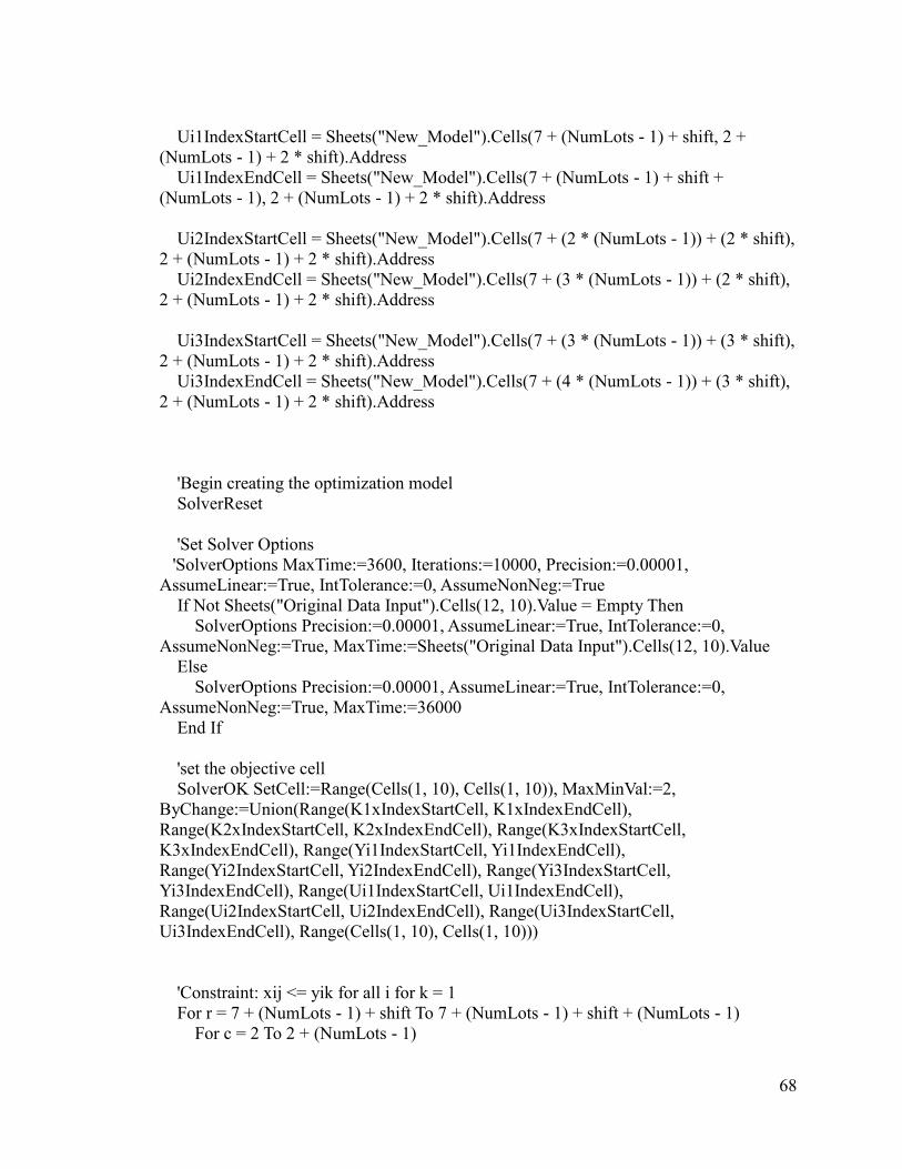
68
Ui1IndexStartCell = Sheets("New_Model").Cells(7 + (NumLots - 1) + shift, 2 +
(NumLots - 1) + 2 * shift).Address
Ui1IndexEndCell = Sheets("New_Model").Cells(7 + (NumLots - 1) + shift +
(NumLots - 1), 2 + (NumLots - 1) + 2 * shift).Address
Ui2IndexStartCell = Sheets("New_Model").Cells(7 + (2 * (NumLots - 1)) + (2 * shift),
2 + (NumLots - 1) + 2 * shift).Address
Ui2IndexEndCell = Sheets("New_Model").Cells(7 + (3 * (NumLots - 1)) + (2 * shift),
2 + (NumLots - 1) + 2 * shift).Address
Ui3IndexStartCell = Sheets("New_Model").Cells(7 + (3 * (NumLots - 1)) + (3 * shift),
2 + (NumLots - 1) + 2 * shift).Address
Ui3IndexEndCell = Sheets("New_Model").Cells(7 + (4 * (NumLots - 1)) + (3 * shift),
2 + (NumLots - 1) + 2 * shift).Address
'Begin creating the optimization model
SolverReset
'Set Solver Options
'SolverOptions MaxTime:=3600, Iterations:=10000, Precision:=0.00001,
AssumeLinear:=True, IntTolerance:=0, AssumeNonNeg:=True
If Not Sheets("Original Data Input").Cells(12, 10).Value = Empty Then
SolverOptions Precision:=0.00001, AssumeLinear:=True, IntTolerance:=0,
AssumeNonNeg:=True, MaxTime:=Sheets("Original Data Input").Cells(12, 10).Value
Else
SolverOptions Precision:=0.00001, AssumeLinear:=True, IntTolerance:=0,
AssumeNonNeg:=True, MaxTime:=36000
End If
'set the objective cell
SolverOK SetCell:=Range(Cells(1, 10), Cells(1, 10)), MaxMinVal:=2,
ByChange:=Union(Range(K1xIndexStartCell, K1xIndexEndCell),
Range(K2xIndexStartCell, K2xIndexEndCell), Range(K3xIndexStartCell,
K3xIndexEndCell), Range(Yi1IndexStartCell, Yi1IndexEndCell),
Range(Yi2IndexStartCell, Yi2IndexEndCell), Range(Yi3IndexStartCell,
Yi3IndexEndCell), Range(Ui1IndexStartCell, Ui1IndexEndCell),
Range(Ui2IndexStartCell, Ui2IndexEndCell), Range(Ui3IndexStartCell,
Ui3IndexEndCell), Range(Cells(1, 10), Cells(1, 10)))
'Constraint: xij <= yik for all i for k = 1
For r = 7 + (NumLots - 1) + shift To 7 + (NumLots - 1) + shift + (NumLots - 1)
For c = 2 To 2 + (NumLots - 1)
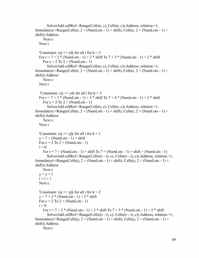
69
SolverAdd cellRef:=Range(Cells(r, c), Cells(r, c)).Address, relation:=1,
formulatext:=Range(Cells(r, 2 + (NumLots - 1) + shift), Cells(r, 2 + (NumLots - 1) +
shift)).Address
Next c
Next r
'Constraint: xij <= yik for all i for k = 2
For r = 7 + 2 * (NumLots - 1) + 2 * shift To 7 + 3 * (NumLots - 1) + 2 * shift
For c = 2 To 2 + (NumLots - 1)
SolverAdd cellRef:=Range(Cells(r, c), Cells(r, c)).Address, relation:=1,
formulatext:=Range(Cells(r, 2 + (NumLots - 1) + shift), Cells(r, 2 + (NumLots - 1) +
shift)).Address
Next c
Next r
'Constraint: xij <= yik for all i for k = 3
For r = 7 + 3 * (NumLots - 1) + 3 * shift To 7 + 4 * (NumLots - 1) + 3 * shift
For c = 2 To 2 + (NumLots - 1)
SolverAdd cellRef:=Range(Cells(r, c), Cells(r, c)).Address, relation:=1,
formulatext:=Range(Cells(r, 2 + (NumLots - 1) + shift), Cells(r, 2 + (NumLots - 1) +
shift)).Address
Next c
Next r
'Constraint: xij <= yjk for all i for k = 1
y = 7 + (NumLots - 1) + shift
For c = 2 To 2 + (NumLots - 1)
i = 0
For r = 7 + (NumLots - 1) + shift To 7 + (NumLots - 1) + shift + (NumLots - 1)
SolverAdd cellRef:=Range(Cells((r - i), c), Cells((r - i), c)).Address, relation:=1,
formulatext:=Range(Cells(y, 2 + (NumLots - 1) + shift), Cells(y, 2 + (NumLots - 1) +
shift)).Address
Next r
y = y + 1
i = i + 1
Next c
'Constraint: xij <= yjk for all i for k = 2
y = 7 + 2 * (NumLots - 1) + 2 * shift
For c = 2 To 2 + (NumLots - 1)
i = 0
For r = 7 + 2 * (NumLots - 1) + 2 * shift To 7 + 3 * (NumLots - 1) + 2 * shift
SolverAdd cellRef:=Range(Cells((r - i), c), Cells((r - i), c)).Address, relation:=1,
formulatext:=Range(Cells(y, 2 + (NumLots - 1) + shift), Cells(y, 2 + (NumLots - 1) +
shift)).Address
Next r

70
y = y + 1
i = i + 1
Next c
'Constraint: xij <= yjk for all i for k = 3
y = 7 + 3 * (NumLots - 1) + 3 * shift
For c = 2 To 2 + (NumLots - 1)
i = 0
For r = 7 + 3 * (NumLots - 1) + 3 * shift To 7 + 4 * (NumLots - 1) + 3 * shift
SolverAdd cellRef:=Range(Cells((r - i), c), Cells((r - i), c)).Address, relation:=1,
formulatext:=Range(Cells(y, 2 + (NumLots - 1) + shift), Cells(y, 2 + (NumLots - 1) +
shift)).Address
Next r
y = y + 1
i = i + 1
Next c
' Constraint: sum of xij rows for all of the ks equal to 1
For r = 7 + (NumLots - 1) + shift To 7 + 2 * (NumLots - 1) + shift
Sheets("New_Model").Cells(r + (2 * (NumLots - 1)) + (2 * shift), 2 + (NumLots - 1)
+ 3 * shift).Formula = "=SUM(" & Range(Cells(r, 2), Cells(r, 2 + (NumLots -
1))).Address(False, False) & ") +SUM(" & Range(Cells(r + (NumLots - 1) + shift, 2),
Cells(r + (NumLots - 1) + shift, 2 + (NumLots - 1))).Address(False, False) & ") +SUM("
& Range(Cells(r + (2 * (NumLots - 1)) + 2 * shift, 2), Cells(r + (2 * (NumLots - 1)) + 2 *
shift, 2 + (NumLots - 1))).Address(False, False) & ") "
Next r
SolverAdd cellRef:=Range(Cells(7 + 3 * (NumLots - 1) + 3 * shift, 2 + (NumLots - 1)
+ 3 * shift), Cells(7 + 4 * (NumLots - 1) + 3 * shift, 2 + (NumLots - 1) + 3 *
shift)).Address, relation:=2, formulatext:=1
' Constraint: sum of xij columns for all of the ks equal to 1
For c = 2 To 2 + (NumLots - 1)
Sheets("New_Model").Cells(7 + (4 * (NumLots - 1)) + (4 * shift), c).Formula =
"=SUM(" & Range(Cells(7 + (NumLots - 1) + shift, c), Cells(7 + 2 * (NumLots - 1) +
shift, c)).Address(False, False) & ") +SUM(" & Range(Cells(7 + 2 * (NumLots - 1) + 2 *
shift, c), Cells(7 + 3 * (NumLots - 1) + 2 * shift, c)).Address(False, False) & ") +SUM("
& Range(Cells(7 + 3 * (NumLots - 1) + 3 * shift, c), Cells(7 + 4 * (NumLots - 1) + 3 *
shift, c)).Address(False, False) & ") "
Next c
SolverAdd cellRef:=Range(Cells(7 + 4 * (NumLots - 1) + 4 * shift, 2), Cells(7 + 4 *
(NumLots - 1) + 4 * shift, 2 + (NumLots - 1))).Address, relation:=2, formulatext:=1
' Constraint: sum of yik values for all of the ks equal to 1
For r = 7 + (NumLots - 1) + shift To 7 + 2 * (NumLots - 1) + shift
Sheets("New_Model").Cells(r, 2 + (NumLots - 1) + 3 * shift).Formula = "=SUM("
& Range(Cells(r, 2 + (NumLots - 1) + shift), Cells(r, 2 + (NumLots - 1) +
71
shift)).Address(False, False) & ") +SUM(" & Range(Cells(r + (NumLots - 1) + shift, 2 +
(NumLots - 1) + shift), Cells(r + (NumLots - 1) + shift, 2 + (NumLots - 1) +
shift)).Address(False, False) & ") +SUM(" & Range(Cells(r + 2 * (NumLots - 1) + 2 *
shift, 2 + (NumLots - 1) + shift), Cells(r + 2 * (NumLots - 1) + 2 * shift, 2 + (NumLots -
1) + shift)).Address(False, False) & ") "
Next r
SolverAdd cellRef:=Range(Cells(7 + (NumLots - 1) + shift, 2 + (NumLots - 1) + 3 *
shift), Cells(7 + 2 * (NumLots - 1) + shift, 2 + (NumLots - 1) + 3 * shift)).Address,
relation:=2, formulatext:=1
'Assign the largest non 10 inch lot to Production Line 4 (3rd Production Line)
LongestTime = 0
LineFourAnchorIndex = -1
For r = 7 To 7 + (NumLots - 1)
If Sheets("Data").Cells(r - 5, 5) <> 10 Then
If LongestTime < Sheets("New_Model").Cells(r, 2 + (NumLots - 1) + shift).Value
Then
LongestTime = Sheets("New_Model").Cells(r, 2 + (NumLots - 1) + shift).Value
LineFourAnchorIndex = r - 6
LineOneSize = Sheets("Data").Cells(r - 5, 5)
End If
End If
Next r
'Add constraint that forces the y value for the lot we assigned to Production Line 4 to
be 1
SolverAdd cellRef:=Range(Cells(7 + 3 * (NumLots - 1) + 3 * shift +
(LineFourAnchorIndex - 1), 2 + (NumLots - 1) + shift), Cells(7 + 3 * (NumLots - 1) + 3
* shift + (LineFourAnchorIndex - 1), 2 + (NumLots - 1) + shift)).Address, relation:=2,
formulatext:=1
'Assign the largest lot that is not the size of the lot assigned to Production Line 4 to
Production Line 2 (2nd Production Line)
LineTwoSize = -1
LongestTime = 0
LineTwoAnchorIndex = -1
For r = 7 To 7 + (NumLots - 1)
If Sheets("Data").Cells(r - 5, 5) <> LineOneSize Then
If LongestTime < Sheets("New_Model").Cells(r, 2 + (NumLots - 1) + shift).Value
Then
LongestTime = Sheets("New_Model").Cells(r, 2 + (NumLots - 1) + shift).Value
LineTwoAnchorIndex = r - 6
LineTwoSize = Sheets("Data").Cells(r - 5, 5)
End If
End If
Next r

72
'Add constraint that forces the y value for the lot we assigned to Production Line 2 to
be 1
SolverAdd cellRef:=Range(Cells(7 + 2 * (NumLots - 1) + 2 * shift +
(LineTwoAnchorIndex - 1), 2 + (NumLots - 1) + shift), Cells(7 + 2 * (NumLots - 1) + 2 *
shift + (LineTwoAnchorIndex - 1), 2 + (NumLots - 1) + shift)).Address, relation:=2,
formulatext:=1
'Assign the largest lot that is not the size of Line 4 and not the size of Line 2 to
Production Line 1 (2nd Production Line)
LongestTime = 0
LineOneAnchorIndex = -1
For r = 7 To 7 + (NumLots - 1)
If Sheets("Data").Cells(r - 5, 5) <> LineOneSize And Sheets("Data").Cells(r - 5, 5)
<> LineTwoSize Then
If LongestTime < Sheets("New_Model").Cells(r, 2 + (NumLots - 1) + shift).Value
Then
LongestTime = Sheets("New_Model").Cells(r, 2 + (NumLots - 1) + shift).Value
LineOneAnchorIndex = r - 6
End If
End If
Next r
'Add constraint that forces the y value for the lot we assigned to Production Line 2 to
be 1
SolverAdd cellRef:=Range(Cells(7 + (NumLots - 1) + shift + (LineOneAnchorIndex -
1), 2 + (NumLots - 1) + shift), Cells(7 + (NumLots - 1) + shift + (LineOneAnchorIndex -
1), 2 + (NumLots - 1) + shift)).Address, relation:=2, formulatext:=1
'Create the ujs for k=1
x = 7 + (NumLots - 1) + shift
For c = 2 To 2 + (NumLots - 1)
Sheets("New_Model").Cells(7 + 2 * (NumLots - 1) + shift + 1, c).Formula = "=" &
Sheets("New_Model").Cells(x, 2 + (NumLots - 1) + 2 * shift).Address(False, False)
x = x + 1
Next c
'Create the matrix formula for k = 1
Sheets("New_Model").Cells(1, 4).Value = NumLots
For c = 2 To 2 + (NumLots - 1)
For r = 7 + (NumLots - 1) + shift To 7 + 2 * (NumLots - 1) + shift
Sheets("New_Model").Cells(r, c + (NumLots - 1) + 4 * shift).Formula = "=" &
Cells(r, c).Address(False, False) & "*" & (NumLots - 1) & "+" & Cells(r, 2 + (NumLots -

73
1) + 2 * shift).Address(False, False) & "-" & Cells(7 + 2 * (NumLots - 1) + shift + 1,
c).Address(False, False) & "+" & (NumLots - 3) & "*" & Cells(c + 5 + (NumLots - 1) +
shift, r - (NumLots - 1) - shift - 5).Address(False, False)
Next r
Next c
'Add the u constraints for k = 1
For r = 7 + (NumLots - 1) + shift To 7 + 2 * (NumLots - 1) + shift
For c = 2 + (NumLots - 1) + 4 * shift To 2 + 2 * (NumLots - 1) + 4 * shift
If (c - (NumLots + (4 * shift))) <> (r - ((NumLots - 1) + 7 + shift - 1)) And ((c -
(NumLots + (4 * shift))) <> LineOneAnchorIndex) And ((r - (NumLots + 7 + shift - 2))
<> LineOneAnchorIndex) Then
SolverAdd cellRef:=Range(Cells(r, c), Cells(r, c)).Address, relation:=1,
formulatext:=(NumLots - 2)
End If
Next c
Next r
'Create the ujs for k=2
x = 7 + 2 * (NumLots - 1) + 2 * shift
For c = 2 To 2 + (NumLots - 1)
Sheets("New_Model").Cells(7 + 3 * (NumLots - 1) + (2 * shift) + 1, c).Formula =
"=" & Sheets("New_Model").Cells(x, 2 + (NumLots - 1) + 2 * shift).Address(False,
False)
x = x + 1
Next c
'Create the matrix formula for k = 2
For c = 2 To 2 + (NumLots - 1)
For r = 7 + 2 * (NumLots - 1) + 2 * shift To 7 + 3 * (NumLots - 1) + 2 * shift
Sheets("New_Model").Cells(r, c + (NumLots - 1) + 4 * shift).Formula = "=" &
Cells(r, c).Address(False, False) & "*" & (NumLots - 1) & "+" & Cells(r, 2 + (NumLots -
1) + 2 * shift).Address(False, False) & "-" & Cells(7 + 3 * (NumLots - 1) + (2 * shift) +
1, c).Address(False, False) & "+" & (NumLots - 3) & "*" & Cells(c + 5 + 2 * (NumLots -
1) + 2 * shift, r - 2 * (NumLots - 1) - 2 * shift - 5).Address(False, False)
Next r
Next c
'Add the u constraints for k= 2
For r = 7 + 2 * (NumLots - 1) + 2 * shift To 7 + 3 * (NumLots - 1) + 2 * shift
For c = 2 + (NumLots - 1) + 4 * shift To 2 + 2 * (NumLots - 1) + 4 * shift
If (c - (NumLots + (4 * shift))) <> (r - (2 * (NumLots - 1) + 7 + 2 * shift - 1)) And
_
((c - (NumLots + (4 * shift))) <> LineTwoAnchorIndex) And _
((r - (2 * (NumLots - 1) + 7 + 2 * shift - 1)) <> LineTwoAnchorIndex) Then

74
SolverAdd cellRef:=Range(Cells(r, c), Cells(r, c)).Address, relation:=1,
formulatext:=(NumLots - 2)
End If
Next c
Next r
'Create the ujs for k=3
x = 7 + 3 * (NumLots - 1) + 3 * shift
For c = 2 To 2 + (NumLots - 1)
Sheets("New_Model").Cells(7 + 4 * (NumLots - 1) + (3 * shift) + 1, c).Formula =
"=" & Sheets("New_Model").Cells(x, 2 + (NumLots - 1) + 2 * shift).Address(False,
False)
x = x + 1
Next c
'Create the matrix formula for k = 3 fix this
For c = 2 To 2 + (NumLots - 1)
For r = 7 + 3 * (NumLots - 1) + 3 * shift To 7 + 4 * (NumLots - 1) + 3 * shift
Sheets("New_Model").Cells(r, c + (NumLots - 1) + 4 * shift).Formula = "=" &
Cells(r, c).Address(False, False) & "*" & (NumLots - 1) & "+" & Cells(r, 2 + (NumLots -
1) + 2 * shift).Address(False, False) & "-" & Cells(7 + 4 * (NumLots - 1) + (3 * shift) +
1, c).Address(False, False) & "+" & (NumLots - 3) & "*" & Cells(c + 5 + 3 * (NumLots -
1) + 3 * shift, r - 3 * (NumLots - 1) - 3 * shift - 5).Address(False, False)
Next r
Next c
'Add the u constraints for k = 3
For r = 7 + 3 * (NumLots - 1) + 3 * shift To 7 + 4 * (NumLots - 1) + 3 * shift
For c = 2 + (NumLots - 1) + 4 * shift To 2 + 2 * (NumLots - 1) + 4 * shift
If (c - (NumLots + (4 * shift))) <> (r - (3 * (NumLots - 1) + 7 + 3 * shift - 1)) And
_
((c - (NumLots + (4 * shift))) <> LineFourAnchorIndex) And _
((r - (3 * (NumLots - 1) + 7 + 3 * shift - 1)) <> LineFourAnchorIndex) Then
SolverAdd cellRef:=Range(Cells(r, c), Cells(r, c)).Address, relation:=1,
formulatext:=(NumLots - 2)
End If
Next c
Next r
'Add constraints that ensure machines are not going over capacity
Sheets("New_Model").Cells(1, 26).Formula = "=SumProduct(" &
Range(ProcessIndexStartCell, ProcessIndexEndCell).Address(False, False) & "," &
Range(Yi1IndexStartCell, Yi1IndexEndCell).Address(False, False) & ")"

75
Sheets("New_Model").Cells(2, 26).Formula = "=SumProduct(" &
Range(ProcessIndexStartCell, ProcessIndexEndCell).Address(False, False) & "," &
Range(Yi2IndexStartCell, Yi2IndexEndCell).Address(False, False) & ")"
Sheets("New_Model").Cells(3, 26).Formula = "=SumProduct(" &
Range(ProcessIndexStartCell, ProcessIndexEndCell).Address(False, False) & "," &
Range(Yi3IndexStartCell, Yi3IndexEndCell).Address(False, False) & ")"
'Write Line max capacities on the model
Sheets("New_Model").Cells(1, 27).Value = Sheets("Original Data Input").Cells(6,
10).Value
Sheets("New_Model").Cells(2, 27).Value = Sheets("Original Data Input").Cells(7,
10).Value
Sheets("New_Model").Cells(3, 27).Value = Sheets("Original Data Input").Cells(8,
10).Value
SolverAdd cellRef:=Range(Cells(1, 26), Cells(1, 26)).Address, relation:=1,
formulatext:=Cells(1, 27).Address
SolverAdd cellRef:=Range(Cells(2, 26), Cells(2, 26)).Address, relation:=1,
formulatext:=Cells(2, 27).Address
SolverAdd cellRef:=Range(Cells(3, 26), Cells(3, 26)).Address, relation:=1,
formulatext:=Cells(3, 27).Address
'add binary constraints for xij, and yik
SolverAdd cellRef:=Range(K1xIndexStartCell, K1xIndexEndCell).Address,
relation:=5
SolverAdd cellRef:=Range(K2xIndexStartCell, K2xIndexEndCell).Address,
relation:=5
SolverAdd cellRef:=Range(K3xIndexStartCell, K3xIndexEndCell).Address,
relation:=5
SolverAdd cellRef:=Range(Yi1IndexStartCell, Yi1IndexEndCell).Address, relation:=5
SolverAdd cellRef:=Range(Yi2IndexStartCell, Yi2IndexEndCell).Address, relation:=5
SolverAdd cellRef:=Range(Yi3IndexStartCell, Yi3IndexEndCell).Address, relation:=5
SolverAdd cellRef:=Range(Ui1IndexStartCell, Ui1IndexEndCell).Address,
relation:=3, formulatext:=0
SolverAdd cellRef:=Range(Ui2IndexStartCell, Ui2IndexEndCell).Address,
relation:=3, formulatext:=0
SolverAdd cellRef:=Range(Ui3IndexStartCell, Ui3IndexEndCell).Address,
relation:=3, formulatext:=0
'Add the ui<= n*yik constraint for k = 1
For r = 7 + (NumLots - 1) + shift To 7 + 2 * (NumLots - 1) + shift
Sheets("New_Model").Cells(r, 2 + (NumLots - 1) + shift + 1).Formula = "=" &
NumLots & "*" & Cells(r, 2 + (NumLots - 1) + shift).Address(False, False)

76
Next r
SolverAdd cellRef:=Range(Ui1IndexStartCell, Ui1IndexEndCell).Address,
relation:=1, formulatext:=Range(Cells(7 + (NumLots - 1) + shift, 2 + (NumLots - 1) +
shift + 1), Cells(7 + 2 * (NumLots - 1) + shift, 2 + (NumLots - 1) + shift + 1))
'Add the ui<= n*yik constraint for k = 2
For r = 7 + 2 * (NumLots - 1) + 2 * shift To 7 + 3 * (NumLots - 1) + 2 * shift
Sheets("New_Model").Cells(r, 2 + (NumLots - 1) + shift + 1).Formula = "=" &
NumLots & "*" & Cells(r, 2 + (NumLots - 1) + shift).Address(False, False)
Next r
SolverAdd cellRef:=Range(Ui2IndexStartCell, Ui2IndexEndCell).Address,
relation:=1, formulatext:=Range(Cells(7 + 2 * (NumLots - 1) + 2 * shift, 2 + (NumLots -
1) + shift + 1), Cells(7 + 3 * (NumLots - 1) + 2 * shift, 2 + (NumLots - 1) + shift + 1))
'Add the ui<= n*yik constraint for k = 3
For r = 7 + 3 * (NumLots - 1) + 3 * shift To 7 + 4 * (NumLots - 1) + 3 * shift
Sheets("New_Model").Cells(r, 2 + (NumLots - 1) + shift + 1).Formula = "=" &
NumLots & "*" & Cells(r, 2 + (NumLots - 1) + shift).Address(False, False)
Next r
SolverAdd cellRef:=Range(Ui3IndexStartCell, Ui3IndexEndCell).Address,
relation:=1, formulatext:=Range(Cells(7 + 3 * (NumLots - 1) + 3 * shift, 2 + (NumLots -
1) + shift + 1), Cells(7 + 4 * (NumLots - 1) + 3 * shift, 2 + (NumLots - 1) + shift + 1))
'10 inch lots cant go to line 4 constraint
For r = 2 To 2 + (NumLots - 1)
If Sheets("Data").Cells(r, 5) = 10 Then
SolverAdd cellRef:=Range(Cells(6 + 3 * (NumLots - 1) + (3 * shift) + (r - 1), 2 +
(NumLots - 1) + shift), Cells(6 + 3 * (NumLots - 1) + (3 * shift) + (r - 1), 2 + (NumLots -
1) + shift)).Address, relation:=2, formulatext:=0
End If
Next r
' make the diagonal xij varibles 0 for k = 1
col = 2
For r = 7 + (NumLots - 1) + shift To 7 + 2 * (NumLots - 1) + shift
SolverAdd cellRef:=Range(Cells(r, col), Cells(r, col)).Address, relation:=2,
formulatext:=0
col = col + 1
Next r
' make the diagonal xij varibles 0 for k = 2
col = 2
For r = 7 + 2 * (NumLots - 1) + 2 * shift To 7 + 3 * (NumLots - 1) + 2 * shift

77
SolverAdd cellRef:=Range(Cells(r, col), Cells(r, col)).Address, relation:=2,
formulatext:=0
col = col + 1
Next r
' make the diagonal xij varibles 0 for k = 3
col = 2
For r = 7 + 3 * (NumLots - 1) + 3 * shift To 7 + 4 * (NumLots - 1) + 3 * shift
SolverAdd cellRef:=Range(Cells(r, col), Cells(r, col)).Address, relation:=2,
formulatext:=0
col = col + 1
Next r
'add the constraint that changeover times + process times for line 1 <= q
Sheets("New_Model").Cells(1, 12).Formula = "=SumProduct(" &
Range(DistIndexStartCell, DistIndexEndCell).Address(False, False) & "," &
Range(K1xIndexStartCell, K1xIndexEndCell).Address(False, False) & ") +SumProduct("
& Range(ProcessIndexStartCell, ProcessIndexEndCell).Address(False, False) & "," &
Range(Yi1IndexStartCell, Yi1IndexEndCell).Address(False, False) & ")"
Sheets("New_Model").Cells(2, 12).Formula = "=SumProduct(" &
Range(DistIndexStartCell, DistIndexEndCell).Address(False, False) & "," &
Range(K2xIndexStartCell, K2xIndexEndCell).Address(False, False) & ") +SumProduct("
& Range(ProcessIndexStartCell, ProcessIndexEndCell).Address(False, False) & "," &
Range(Yi2IndexStartCell, Yi2IndexEndCell).Address(False, False) & ")"
Sheets("New_Model").Cells(3, 12).Formula = "=0.5 * (SumProduct(" &
Range(DistIndexStartCell, DistIndexEndCell).Address(False, False) & "," &
Range(K3xIndexStartCell, K3xIndexEndCell).Address(False, False) & ") +SumProduct("
& Range(ProcessIndexStartCell, ProcessIndexEndCell).Address(False, False) & "," &
Range(Yi3IndexStartCell, Yi3IndexEndCell).Address(False, False) & "))"
SolverAdd cellRef:=Range(Cells(1, 12), Cells(1, 12)).Address, relation:=1,
formulatext:=Range(Cells(1, 10), Cells(1, 10)).Address
SolverAdd cellRef:=Range(Cells(2, 12), Cells(2, 12)).Address, relation:=1,
formulatext:=Range(Cells(1, 10), Cells(1, 10)).Address
SolverAdd cellRef:=Range(Cells(3, 12), Cells(3, 12)).Address, relation:=1,
formulatext:=Range(Cells(1, 10), Cells(1, 10)).Address
Sheets("New_Model").Cells(1, 1).Value = "passF"
Sheets("New_Model").Cells(1, 2).Value = 1000
Sheets("New_Model").Cells(2, 1).Value = "preprocess"
Sheets("New_Model").Cells(2, 2).Value = "on"
SetSolverParameters "CBC", Range("A1:B2"), Sheets("New_Model")
Dim ReturnValue As OpenSolverResult

78
ReturnValue = RunOpenSolver(False, True)
'create the match function for line 1
IndexValue = 1
For r = 7 + (NumLots - 1) + shift To 7 + 2 * (NumLots - 1) + shift
Sheets("New_Model").Cells(r, 2 + 2 * (NumLots - 1) + 5 * shift).Formula = "=" &
IndexValue
IndexValue = IndexValue + 1
Next r
For r = 7 + (NumLots - 1) + shift To 7 + 2 * (NumLots - 1) + shift
Sheets("New_Model").Cells(r, 2 + 2 * (NumLots - 1) + 5 * shift + 1).Formula =
"=Match(1," & Range(Cells(r, 2), Cells(r, 2 + (NumLots - 1))).Address(False, False) &
",0)"
Next r
'create the match function for line 2
IndexValue = 1
For r = 7 + 2 * (NumLots - 1) + 2 * shift To 7 + 3 * (NumLots - 1) + 2 * shift
Sheets("New_Model").Cells(r, 2 + 2 * (NumLots - 1) + 5 * shift).Formula = "=" &
IndexValue
IndexValue = IndexValue + 1
Next r
For r = 7 + 2 * (NumLots - 1) + 2 * shift To 7 + 3 * (NumLots - 1) + 2 * shift
Sheets("New_Model").Cells(r, 2 + 2 * (NumLots - 1) + 5 * shift + 1).Formula =
"=Match(1," & Range(Cells(r, 2), Cells(r, 2 + (NumLots - 1))).Address(False, False) &
",0)"
Next r
'create the match function for line 3
IndexValue = 1
For r = 7 + 3 * (NumLots - 1) + 3 * shift To 7 + 4 * (NumLots - 1) + 3 * shift
Sheets("New_Model").Cells(r, 2 + 2 * (NumLots - 1) + 5 * shift).Formula = "=" &
IndexValue
IndexValue = IndexValue + 1
Next r
For r = 7 + 3 * (NumLots - 1) + 3 * shift To 7 + 4 * (NumLots - 1) + 3 * shift
Sheets("New_Model").Cells(r, 2 + 2 * (NumLots - 1) + 5 * shift + 1).Formula =
"=Match(1," & Range(Cells(r, 2), Cells(r, 2 + (NumLots - 1))).Address(False, False) &
",0)"
Next r
Dim wa As Worksheet
For Each wa In Worksheets
79
If wa.Name = "Optimized_Schedule" Then
Application.DisplayAlerts = False
Sheets("Optimized_Schedule").Delete
Application.DisplayAlerts = True
End If
Next
Sheets.Add.Name = "Optimized_Schedule"
Sheets("Optimized_Schedule").Cells(2, 2) = LineOneAnchorIndex
Sheets("Optimized_Schedule").Cells(2, 5) = LineTwoAnchorIndex
Sheets("Optimized_Schedule").Cells(2, 8) = LineFourAnchorIndex
'Count the number of lots assigned to production line 1
Yi1Count = 0
For r = 7 + (NumLots - 1) + shift To 7 + 2 * (NumLots - 1) + shift
If Sheets("New_Model").Cells(r, 2 + (NumLots - 1) + shift).Value = 1 Then
Yi1Count = Yi1Count + 1
End If
Next r
'Perform the lookup function only the amount of times equal to the count
For r = 3 To 3 + (Yi1Count - 2)
Sheets("Optimized_Schedule").Cells(r, 2).Formula = "=VLOOKUP(" & Cells(r - 1,
2).Address(False, False) & ",New_Model!" & Range(Cells(7 + (NumLots - 1) + shift, 2 +
2 * (NumLots - 1) + 5 * shift), Cells(7 + 2 * (NumLots - 1) + shift, 2 + 2 * (NumLots - 1)
+ 5 * shift + 1)).Address(True, True) & ",2)"
Next r
'Find the catalog number from the original data input that corresponds to index value
For r = 2 To 2 + (Yi1Count - 1)
Sheets("Optimized_Schedule").Cells(r, 3).Value = Sheets("Original Data
Input").Cells(Sheets("Optimized_Schedule").Cells(r, 2).Value + 1, 2)
Next r
'Count the number of lots assigned to production line 2
Yi2Count = 0
For r = 7 + 2 * (NumLots - 1) + 2 * shift To 7 + 3 * (NumLots - 1) + 2 * shift
If Sheets("New_Model").Cells(r, 2 + (NumLots - 1) + shift).Value = 1 Then
Yi2Count = Yi2Count + 1
End If
Next r
'Perform the lookup function only the amount of times equal to the count for line 2
For r = 3 To 3 + (Yi2Count - 2)
Sheets("Optimized_Schedule").Cells(r, 5).Formula = "=VLOOKUP(" & Cells(r - 1,
5).Address(False, False) & ",New_Model!" & Range(Cells(7 + 2 * (NumLots - 1) + 2 *

80
shift, 2 + 2 * (NumLots - 1) + 5 * shift), Cells(7 + 3 * (NumLots - 1) + 2 * shift, 2 + 2 *
(NumLots - 1) + 5 * shift + 1)).Address(True, True) & ",2)"
Next r
'Find the catalog number from the original data input that corresponds to index value
For r = 2 To 2 + (Yi2Count - 1)
Sheets("Optimized_Schedule").Cells(r, 6).Value = Sheets("Original Data
Input").Cells(Sheets("Optimized_Schedule").Cells(r, 5).Value + 1, 2)
Next r
'Count the number of lots assigned to production line 3
Yi3Count = 0
For r = 7 + 3 * (NumLots - 1) + 3 * shift To 7 + 4 * (NumLots - 1) + 3 * shift
If Sheets("New_Model").Cells(r, 2 + (NumLots - 1) + shift).Value = 1 Then
Yi3Count = Yi3Count + 1
End If
Next r
'Perform the lookup function only the amount of times equal to the count
For r = 3 To 3 + (Yi3Count - 2)
Sheets("Optimized_Schedule").Cells(r, 8).Formula = "=VLOOKUP(" & Cells(r - 1,
8).Address(False, False) & ",New_Model!" & Range(Cells(7 + 3 * (NumLots - 1) + 3 *
shift, 2 + 2 * (NumLots - 1) + 5 * shift), Cells(7 + 4 * (NumLots - 1) + 3 * shift, 2 + 2 *
(NumLots - 1) + 5 * shift + 1)).Address(True, True) & ",2)"
Next r
'Find the catalog number from the original data input that corresponds to index value
For r = 2 To 2 + (Yi3Count - 1)
Sheets("Optimized_Schedule").Cells(r, 9).Value = Sheets("Original Data
Input").Cells(Sheets("Optimized_Schedule").Cells(r, 8).Value + 1, 2)
Next r
Sheets("Optimized_Schedule").Cells(1, 2).Value = "XL1 Schedule"
Sheets("Optimized_Schedule").Cells(1, 5).Value = "XL2 Schedule"
Sheets("Optimized_Schedule").Cells(1, 8).Value = "XL4 Schedule"
'Write optimized value in the Optimized Schedule Sheet
'The writing would not give the right value as it added the cost of the changeover from
the last lot back to the first lot
'Therefore as of now it is commented out, in the future this code can be used to write
optimized value in the sheet
'Sheets("New_Model").Cells(1, 15).Formula = "=SumProduct(" &
Range(DistIndexStartCell, DistIndexEndCell).Address(False, False) & "," &
Range(K1xIndexStartCell, K1xIndexEndCell).Address(False, False) & ") +SumProduct("
& Range(DistIndexStartCell, DistIndexEndCell).Address(False, False) & "," &

81
Range(K2xIndexStartCell, K2xIndexEndCell).Address(False, False) & ") +SumProduct("
& Range(DistIndexStartCell, DistIndexEndCell).Address(False, False) & "," &
Range(K3xIndexStartCell, K3xIndexEndCell).Address(False, False) & ")"
'Sheets("Optimized_Schedule").Cells(1, 20).Value = Sheets("New_Model").Cells(1,
15).Value
Sheets("New_Model").Visible = xlSheetHidden
Sheets("Data").Visible = xlSheetHidden
'Turn on screen updating after performing tasks
Application.ScreenUpdating = True
End Sub

82
Appendix J: Production Schedule Optimization Tool User Instructions
Please apply the following instructions to optimize the schedule:
1. Open the "Original Data Input" tab, and select the data in columns A through D,
starting from row 2
2. Select all of the data from row 2 to where the data ends, and press delete to clear
the data
3. Starting from row 2 column A, input the appropriate catalog numbers, quantity
started and ID number
Note:
To test the model, start with scheduling smaller number of lots for
1-2 days (about 20-26 lots)
Slowly scale up the model as you see appropriate. Currently the
model can only schedule up to 40 lots
4. Date Started column is not essential for the model to run, therefore it is optional
5. Make sure that ID number is in column A, Item number is in column B and
Quantity Started is in column D
Note:
Quantity started is the amount of boxes, not the amount of filter
units. For example for a 2 inch lot quantity started can be 2, this
would mean 2*3 = 6 units are being produced, since 2 inch filters
are usually 3 units per box.
6. Make sure that among the data inputted there are at least 3 different size lots to
ensure the model works properly
Note:
It is possible to improve the code to eliminate this requirement
7. Make changes to the "conversion of changeover tasks" region if necessary. The
values are how long it would add to changeover to make each change
8. Input the maximum capacity for each line so that scheduling do not cause a
machine to go over capacity
Note:

83
Machine capacities have to be filled for the model to work, they
cannot be left blank
9. Fill out the maximum time limit permitted for the model (it will output either the
best overall schedule, or the best found schedule thus far)
10. Click "Optimize Schedule" and wait for the model to run. Depending on the time
limit set, this can take hours, please give ample time to the model to run
Note:
You can hit the Esc key to escape the solution at any time. The
more time given, the closer to optimal the solution found will be.
11. Analyze the results and use it to create schedules. The model shows an optimized
schedule, but changes can still be made, it is just a tool to advise.

84
Appendix K: SOP Proposal 1
Steps Task
ID Step Description
1 1
Once the final unit of a work order leaves the Bonder, Operator 1 cleans and
organizes the workstation. During this process the Operator 1 discards scrap
materials and organizes the area corresponding to the Table and Bonder.
Operator 2 will clean their workstation upon the completion of their final
product.
2 2
Operator 1 prepares Quality Assurance sample from the previous work order by
bagging the units and complete corresponding forms. Next, he/she delivers the
sample to the quality testing rack located at the center of the production floor
next to the Production Lead’s desk.
3 3,1
Next, Operator 1 finalizes and organizes the paperwork corresponding to the
previous work order and then hands the paperwork folder to Operator 2.
Operator 2 then completes the paperwork for their workstation and passes the
paperwork folder to the packaging department.
4 4,5,6
Once the paperwork is completed, Operator 1 will walk to the Materials Rack,
grab the housing and cap bags, and set the housings and caps in the bins on the
Table. Then, he/she disposes the bags in the trash can.
5 15,16,
17
Operator 1 selects the Bonder recipe for the upcoming work order. Then, the
Melt Check is performed according to MilliporeSigma’s Bonder SOP and the
paperwork is completed.
6 12,13 Operator 2 sets up the housing integrity test according to MilliporeSigma’s
Housing Integrity Test SOP and completes corresponding paperwork.
7 7,8,9
Once the Housing Integrity Test is set up, Operator 2 walks to the Materials
Rack and grab the cartridges. The cartridges are brought to the Table beside the
Bonder and are counted for accountability purposes. The corresponding
paperwork is then completed by Operator 2.
8 10,11 Next, Operator 2 ensures that all labels are accounted for and attaches a sample
label to the paperwork.
9 21 Operator 2 then completes the changeover procedure for the Welder. This is
described in MilliporeSigma’s Welder SOP.
10 18,19,
20
After Operator 1 finishes the Bonder melt check, he/she walks to the Bubble
and Burst machine to perform the Bubble and Burst Tests according to
MilliporeSigma’s Bubble and Burst Test SOP. Next, Operator 1 completes the
corresponding paperwork to the Bubble and Burst Tests.

85
Appendix L: SOP Proposal 2
Steps Task
ID Step Description
1 4, 5, 6
With nine units remaining in the work order, Operator 1 will prepare sufficient
material between the Bonder and Welder to allocate one minute of queue time.
During the one minute of queue time, Operator 1 will walk to the materials
rack, grab the housing and cap bags, and set the housings and caps in the bins
on the table. Then, he/she disposes the bags in the trash can.
2 7
With at least seven remaining units, Operator 1 will prepare sufficient material
between the Bonder and Welder to allocate fifteen seconds queue time. Then,
Operator 1 then walks to the rack and grabs the cartridges.
3 8 With at least six remaining units, Operator 1 will allocate thirty seconds to
count the cartridges for accountability purposes.
4 9 With at least five remaining units, Operator 1 allocates thirty seconds to
complete the corresponding paperwork to Task 8.
5 10
With at least four remaining units, Operator 1 will set aside fifteen seconds
between wait time for the Bonder and Welder to ensure all labels are accounted
for.
6 11
With at least three remaining units, Operator 1 will set aside thirty seconds
between wait time for the Bonder and Welder to complete the paperwork
associated with label accountability.
7 1
With at least two remaining units, Operator 1 cleans and organizes his/her
workstation. During this process the Operator discards scrap materials and
organizes the area corresponding to the Table and Bonder. Operator 2 will
clean their workstation upon the completion of their final product.
8 2
Operator 1 prepares Quality Assurance sample from the previous work order by
bagging the units and complete corresponding forms. Next, he/she delivers the
sample to the quality testing rack located at the center of the production floor
next to the production lead’s desk.
9 3
Next, operator 1 finalizes and organizes the paperwork corresponding to the
previous work order and then hands the paperwork folder to Operator 2.
Operator 2 then completes the paperwork for their workstation and passes the
paperwork folder to the packaging department.
10 15, 16
Operator 1 selects the Bonder recipe for the upcoming work order. Then, the
melt check is performed according to MilliporeSigma’s Bonder SOP and the
paperwork is completed.
11 12, 13 Operator 2 sets up the Housing Integrity Test according to MilliporeSigma’s
Housing Integrity Test SOP and completes corresponding paperwork.
12 21 Operator 2 then completes the changeover procedure for the Welder. This
procedure is described in MilliporeSigma’s Welder SOP.
13 18,
19, 20
After Operator 1 finishes the Bonder melt check, he/she walks to the Bubble
and Burst machine to perform the Bubble and Burst Tests according to
MilliporeSigma’s Bubble and Burst Test SOP. Next, Operator 1 completes the
corresponding paperwork to the Bubble and Burst Tests.

86
Appendix M: SOP Proposal 3
Steps Task ID Step Description
1 4, 5, 6
With at least thirteen units remaining in the work order, Operator 1 will
prepare sufficient material between the Bonder and Welder to allocate one
minute of queue time. During the one minute of queue time, Operator 1
will walk to the materials rack, grab the housing and cap bags, and set the
housings and caps in the bins on the table. Then, he/she disposes the bags
in the trash can.
2 7
With at least eleven remaining units, Operator 1 will prepare sufficient
material between the Bonder and Welder to allocate fifteen seconds queue
time. Then, Operator 1 then walks to the rack and grabs the cartridges.
3 8 With at least ten remaining units, Operator 1 will allocate thirty seconds to
count the cartridges for accountability purposes.
4 9 With at least nine remaining units, Operator 1 allocates thirty seconds to
complete the corresponding paperwork to Task 8.
5 10
With at least eight remaining units, Operator 1 will set aside fifteen seconds
between wait time for the Bonder and Welder to ensure all labels are
accounted for.
6 11
With at least seven remaining units, Operator 1 will set aside thirty seconds
between wait time for the Bonder and Welder to complete the paperwork
associated with label accountability.
7 2
With at least six remaining units, Operator 1 prepares Quality Assurance
sample from the previous work order by bagging the units and complete
corresponding forms. Next, he/she delivers the sample to the quality testing
rack located at the center of the production floor next to the production
lead’s desk.
8 1
With at least two remaining units Operator 1 cleans and organizes his/her
workstation. During this process the Operator discards scrap materials and
organizes the area corresponding to the Table and Bonder. Operator 2 will
clean their workstation upon the completion of their final product.
9 3
Next, operator 1 finalizes and organizes the paperwork corresponding to
the previous work order and then hands the paperwork folder to Operator 2.
Operator 2 then completes the paperwork for their workstation and passes
the paperwork folder to the packaging department.
10 15, 16
Operator 1 selects the Bonder recipe for the upcoming work order. Then,
the melt check is performed according to MilliporeSigma’s Bonder SOP
and the paperwork is completed.
11 12, 13
Operator 2 sets up the Housing Integrity Test according to
MilliporeSigma’s Housing Integrity Test SOP and completes
corresponding paperwork.
12 21 Operator 2 then completes the changeover procedure for the Welder. This
procedure is described in MilliporeSigma’s Welder SOP.
13 18, 19, 20 After Operator 1 finishes the Bonder melt check, he/she walks to the

87
Bubble and Burst machine to perform the Bubble and Burst Tests
according to MilliporeSigma’s Bubble and Burst Test SOP. Next, Operator
1 completes the corresponding paperwork to the Bubble and Burst Tests.


