Download - Impala SS Handbook

impalaSS
Handbook
Original by Karl Frost "QaloSS"Updated version by Ash Carlton "whteglve"
with help from many others.In conjunction with,
www.impalassforum.com

Introduction.. . . . . . . . . . . . . . . . . . . . . . . . . . . . . . . . . . . . . . . . . . . . . . . . . . . . . . . . . . . . . . . . . . . . . . . . . . . . . . . . . . . . . . . . . . . . . . . . . . . . . . . . . . . . . . . . . . . . . . . . . . . . . . . . . . . . . . . . . . . . . . . . . . . . 4Maintenance.. . . . . . . . . . . . . . . . . . . . . . . . . . . . . . . . . . . . . . . . . . . . . . . . . . . . . . . . . . . . . . . . . . . . . . . . . . . . . . . . . . . . . . . . . . . . . . . . . . . . . . . . . . . . . . . . . . . . . . . . . . . . . . . . . . . . . . . . . . . . . . . . . . . 5Brakes. . . . . . . . . . . . . . . . . . . . . . . . . . . . . . . . . . . . . . . . . . . . . . . . . . . . . . . . . . . . . . . . . . . . . . . . . . . . . . . . . . . . . . . . . . . . . . . . . . . . . . . . . . . . . . . . . . . . . . . . . . . . . . . . . . . . . . . . . . . . . . . . . . . . . . . . . . . 6Stealth Brake Bolt and Metering Bolt Mod.. . . . . . . . . . . . . . . . . . . . . . . . . . . . . . . . . . . . . . . . . . . . . . . . . . . . . . . . . . . . . . . . . . . . . . . . . . . . . . . . . . . . . . . . . . . . . 6
Chassis / Suspension.. . . . . . . . . . . . . . . . . . . . . . . . . . . . . . . . . . . . . . . . . . . . . . . . . . . . . . . . . . . . . . . . . . . . . . . . . . . . . . . . . . . . . . . . . . . . . . . . . . . . . . . . . . . . . . . . . . . . . . . . . . . . . . . . . . . 9Body Bushings, Lower.. . . . . . . . . . . . . . . . . . . . . . . . . . . . . . . . . . . . . . . . . . . . . . . . . . . . . . . . . . . . . . . . . . . . . . . . . . . . . . . . . . . . . . . . . . . . . . . . . . . . . . . . . . . . . . . . . . . . . . . . . . . . . 9Body Bushings, Upper. . . . . . . . . . . . . . . . . . . . . . . . . . . . . . . . . . . . . . . . . . . . . . . . . . . . . . . . . . . . . . . . . . . . . . . . . . . . . . . . . . . . . . . . . . . . . . . . . . . . . . . . . . . . . . . . . . . . . . . . . . . . 1 2Buick Brace.. . . . . . . . . . . . . . . . . . . . . . . . . . . . . . . . . . . . . . . . . . . . . . . . . . . . . . . . . . . . . . . . . . . . . . . . . . . . . . . . . . . . . . . . . . . . . . . . . . . . . . . . . . . . . . . . . . . . . . . . . . . . . . . . . . . . . . . . . . . . 1 2Coil Spring Replacement, Front. . . . . . . . . . . . . . . . . . . . . . . . . . . . . . . . . . . . . . . . . . . . . . . . . . . . . . . . . . . . . . . . . . . . . . . . . . . . . . . . . . . . . . . . . . . . . . . . . . . . . . . . . . . . . . 1 2Coil Spring Replacement, Rear. . . . . . . . . . . . . . . . . . . . . . . . . . . . . . . . . . . . . . . . . . . . . . . . . . . . . . . . . . . . . . . . . . . . . . . . . . . . . . . . . . . . . . . . . . . . . . . . . . . . . . . . . . . . . . . 1 3Rear Control Arm Replacement. . . . . . . . . . . . . . . . . . . . . . . . . . . . . . . . . . . . . . . . . . . . . . . . . . . . . . . . . . . . . . . . . . . . . . . . . . . . . . . . . . . . . . . . . . . . . . . . . . . . . . . . . . . . . . 1 4Rear Control Arm Replacement, Lower.. . . . . . . . . . . . . . . . . . . . . . . . . . . . . . . . . . . . . . . . . . . . . . . . . . . . . . . . . . . . . . . . . . . . . . . . . . . . . . . . . . . . . . . . . . . . . . . . . 1 4Rear Control Arm Replacement, Upper. . . . . . . . . . . . . . . . . . . . . . . . . . . . . . . . . . . . . . . . . . . . . . . . . . . . . . . . . . . . . . . . . . . . . . . . . . . . . . . . . . . . . . . . . . . . . . . . . . 1 5Rear End Bushing Removal. . . . . . . . . . . . . . . . . . . . . . . . . . . . . . . . . . . . . . . . . . . . . . . . . . . . . . . . . . . . . . . . . . . . . . . . . . . . . . . . . . . . . . . . . . . . . . . . . . . . . . . . . . . . . . . . . . . . 1 5Shock Replacement. . . . . . . . . . . . . . . . . . . . . . . . . . . . . . . . . . . . . . . . . . . . . . . . . . . . . . . . . . . . . . . . . . . . . . . . . . . . . . . . . . . . . . . . . . . . . . . . . . . . . . . . . . . . . . . . . . . . . . . . . . . . . . . . . 1 6Sway Bar Replacement, Front. . . . . . . . . . . . . . . . . . . . . . . . . . . . . . . . . . . . . . . . . . . . . . . . . . . . . . . . . . . . . . . . . . . . . . . . . . . . . . . . . . . . . . . . . . . . . . . . . . . . . . . . . . . . . . . . . 1 7
Cooling System.. . . . . . . . . . . . . . . . . . . . . . . . . . . . . . . . . . . . . . . . . . . . . . . . . . . . . . . . . . . . . . . . . . . . . . . . . . . . . . . . . . . . . . . . . . . . . . . . . . . . . . . . . . . . . . . . . . . . . . . . . . . . . . . . . . . . . . . . . 1 8Bleeding The System.. . . . . . . . . . . . . . . . . . . . . . . . . . . . . . . . . . . . . . . . . . . . . . . . . . . . . . . . . . . . . . . . . . . . . . . . . . . . . . . . . . . . . . . . . . . . . . . . . . . . . . . . . . . . . . . . . . . . . . . . . . . . . 1 8Flushing The Radiator. . . . . . . . . . . . . . . . . . . . . . . . . . . . . . . . . . . . . . . . . . . . . . . . . . . . . . . . . . . . . . . . . . . . . . . . . . . . . . . . . . . . . . . . . . . . . . . . . . . . . . . . . . . . . . . . . . . . . . . . . . . . . 1 8Heater Core Flush.. . . . . . . . . . . . . . . . . . . . . . . . . . . . . . . . . . . . . . . . . . . . . . . . . . . . . . . . . . . . . . . . . . . . . . . . . . . . . . . . . . . . . . . . . . . . . . . . . . . . . . . . . . . . . . . . . . . . . . . . . . . . . . . . . . .1 9Temperature Sensor Replacement. . . . . . . . . . . . . . . . . . . . . . . . . . . . . . . . . . . . . . . . . . . . . . . . . . . . . . . . . . . . . . . . . . . . . . . . . . . . . . . . . . . . . . . . . . . . . . . . . . . . . . . . . . . 20Thermostat Replacement. . . . . . . . . . . . . . . . . . . . . . . . . . . . . . . . . . . . . . . . . . . . . . . . . . . . . . . . . . . . . . . . . . . . . . . . . . . . . . . . . . . . . . . . . . . . . . . . . . . . . . . . . . . . . . . . . . . . . . . . . 20
Electrical. . . . . . . . . . . . . . . . . . . . . . . . . . . . . . . . . . . . . . . . . . . . . . . . . . . . . . . . . . . . . . . . . . . . . . . . . . . . . . . . . . . . . . . . . . . . . . . . . . . . . . . . . . . . . . . . . . . . . . . . . . . . . . . . . . . . . . . . . . . . . . . . . . . . .23Headlight Instrument Panel Illumination.. . . . . . . . . . . . . . . . . . . . . . . . . . . . . . . . . . . . . . . . . . . . . . . . . . . . . . . . . . . . . . . . . . . . . . . . . . . . . . . . . . . . . . . . . . . . . . . 23Opti-Spark Installation.. . . . . . . . . . . . . . . . . . . . . . . . . . . . . . . . . . . . . . . . . . . . . . . . . . . . . . . . . . . . . . . . . . . . . . . . . . . . . . . . . . . . . . . . . . . . . . . . . . . . . . . . . . . . . . . . . . . . . . . . . . . 24Opti-Spark Conversion.. . . . . . . . . . . . . . . . . . . . . . . . . . . . . . . . . . . . . . . . . . . . . . . . . . . . . . . . . . . . . . . . . . . . . . . . . . . . . . . . . . . . . . . . . . . . . . . . . . . . . . . . . . . . . . . . . . . . . . . . . . . 25Plug and Wire Change.. . . . . . . . . . . . . . . . . . . . . . . . . . . . . . . . . . . . . . . . . . . . . . . . . . . . . . . . . . . . . . . . . . . . . . . . . . . . . . . . . . . . . . . . . . . . . . . . . . . . . . . . . . . . . . . . . . . . . . . . . . . . 27Changing Plugs, Stock Manifolds. . . . . . . . . . . . . . . . . . . . . . . . . . . . . . . . . . . . . . . . . . . . . . . . . . . . . . . . . . . . . . . . . . . . . . . . . . . . . . . . . . . . . . . . . . . . . . . . . . . . . . . . 28Changing Plugs, Headers. . . . . . . . . . . . . . . . . . . . . . . . . . . . . . . . . . . . . . . . . . . . . . . . . . . . . . . . . . . . . . . . . . . . . . . . . . . . . . . . . . . . . . . . . . . . . . . . . . . . . . . . . . . . . . . . . . . . . 29
Power Antenna Replacement. . . . . . . . . . . . . . . . . . . . . . . . . . . . . . . . . . . . . . . . . . . . . . . . . . . . . . . . . . . . . . . . . . . . . . . . . . . . . . . . . . . . . . . . . . . . . . . . . . . . . . . . . . . . . . . . . . 33Rebuilding A Power Antenna.. . . . . . . . . . . . . . . . . . . . . . . . . . . . . . . . . . . . . . . . . . . . . . . . . . . . . . . . . . . . . . . . . . . . . . . . . . . . . . . . . . . . . . . . . . . . . . . . . . . . . . . . . . . . . . . . . 37Reprogramming Key Fobs.. . . . . . . . . . . . . . . . . . . . . . . . . . . . . . . . . . . . . . . . . . . . . . . . . . . . . . . . . . . . . . . . . . . . . . . . . . . . . . . . . . . . . . . . . . . . . . . . . . . . . . . . . . . . . . . . . . . . . 43
Exhaust. . . . . . . . . . . . . . . . . . . . . . . . . . . . . . . . . . . . . . . . . . . . . . . . . . . . . . . . . . . . . . . . . . . . . . . . . . . . . . . . . . . . . . . . . . . . . . . . . . . . . . . . . . . . . . . . . . . . . . . . . . . . . . . . . . . . . . . . . . . . . . . . . . . . . . . 45EGR Valve Replacement. . . . . . . . . . . . . . . . . . . . . . . . . . . . . . . . . . . . . . . . . . . . . . . . . . . . . . . . . . . . . . . . . . . . . . . . . . . . . . . . . . . . . . . . . . . . . . . . . . . . . . . . . . . . . . . . . . . . . . . . . 48
Fuel System.. . . . . . . . . . . . . . . . . . . . . . . . . . . . . . . . . . . . . . . . . . . . . . . . . . . . . . . . . . . . . . . . . . . . . . . . . . . . . . . . . . . . . . . . . . . . . . . . . . . . . . . . . . . . . . . . . . . . . . . . . . . . . . . . . . . . . . . . . . . . . . . 50Fuel Filter Change.. . . . . . . . . . . . . . . . . . . . . . . . . . . . . . . . . . . . . . . . . . . . . . . . . . . . . . . . . . . . . . . . . . . . . . . . . . . . . . . . . . . . . . . . . . . . . . . . . . . . . . . . . . . . . . . . . . . . . . . . . . . . . . . . . . 50Fuel Pump Removal. . . . . . . . . . . . . . . . . . . . . . . . . . . . . . . . . . . . . . . . . . . . . . . . . . . . . . . . . . . . . . . . . . . . . . . . . . . . . . . . . . . . . . . . . . . . . . . . . . . . . . . . . . . . . . . . . . . . . . . . . . . . . . . . 50Repairing the Fuel SSender. . . . . . . . . . . . . . . . . . . . . . . . . . . . . . . . . . . . . . . . . . . . . . . . . . . . . . . . . . . . . . . . . . . . . . . . . . . . . . . . . . . . . . . . . . . . . . . . . . . . . . . . . . . . . . . . . . . . . 54New Sending Unit. . . . . . . . . . . . . . . . . . . . . . . . . . . . . . . . . . . . . . . . . . . . . . . . . . . . . . . . . . . . . . . . . . . . . . . . . . . . . . . . . . . . . . . . . . . . . . . . . . . . . . . . . . . . . . . . . . . . . . . . . . . . . . . . . . . 60
General Maintenance.. . . . . . . . . . . . . . . . . . . . . . . . . . . . . . . . . . . . . . . . . . . . . . . . . . . . . . . . . . . . . . . . . . . . . . . . . . . . . . . . . . . . . . . . . . . . . . . . . . . . . . . . . . . . . . . . . . . . . . . . . . . . . . . . .62Air Filter Replacement. . . . . . . . . . . . . . . . . . . . . . . . . . . . . . . . . . . . . . . . . . . . . . . . . . . . . . . . . . . . . . . . . . . . . . . . . . . . . . . . . . . . . . . . . . . . . . . . . . . . . . . . . . . . . . . . . . . . . . . . . . . . 62Broken Window Roller Fix.. . . . . . . . . . . . . . . . . . . . . . . . . . . . . . . . . . . . . . . . . . . . . . . . . . . . . . . . . . . . . . . . . . . . . . . . . . . . . . . . . . . . . . . . . . . . . . . . . . . . . . . . . . . . . . . . . . . . 62Differential Oil Change.. . . . . . . . . . . . . . . . . . . . . . . . . . . . . . . . . . . . . . . . . . . . . . . . . . . . . . . . . . . . . . . . . . . . . . . . . . . . . . . . . . . . . . . . . . . . . . . . . . . . . . . . . . . . . . . . . . . . . . . . . . 70Door Panel Removal. . . . . . . . . . . . . . . . . . . . . . . . . . . . . . . . . . . . . . . . . . . . . . . . . . . . . . . . . . . . . . . . . . . . . . . . . . . . . . . . . . . . . . . . . . . . . . . . . . . . . . . . . . . . . . . . . . . . . . . . . . . . . . . 71Oil Change.. . . . . . . . . . . . . . . . . . . . . . . . . . . . . . . . . . . . . . . . . . . . . . . . . . . . . . . . . . . . . . . . . . . . . . . . . . . . . . . . . . . . . . . . . . . . . . . . . . . . . . . . . . . . . . . . . . . . . . . . . . . . . . . . . . . . . . . . . . . . . .72Resetting the Change Oil Light. . . . . . . . . . . . . . . . . . . . . . . . . . . . . . . . . . . . . . . . . . . . . . . . . . . . . . . . . . . . . . . . . . . . . . . . . . . . . . . . . . . . . . . . . . . . . . . . . . . . . . . . . . . . 72
Oxygen Sensor Replacement. . . . . . . . . . . . . . . . . . . . . . . . . . . . . . . . . . . . . . . . . . . . . . . . . . . . . . . . . . . . . . . . . . . . . . . . . . . . . . . . . . . . . . . . . . . . . . . . . . . . . . . . . . . . . . . . . . 73PCV Valve Replacement. . . . . . . . . . . . . . . . . . . . . . . . . . . . . . . . . . . . . . . . . . . . . . . . . . . . . . . . . . . . . . . . . . . . . . . . . . . . . . . . . . . . . . . . . . . . . . . . . . . . . . . . . . . . . . . . . . . . . . . . . 73Transmission Fluid Change.. . . . . . . . . . . . . . . . . . . . . . . . . . . . . . . . . . . . . . . . . . . . . . . . . . . . . . . . . . . . . . . . . . . . . . . . . . . . . . . . . . . . . . . . . . . . . . . . . . . . . . . . . . . . . . . . . . . . 74
ModificationSS.. . . . . . . . . . . . . . . . . . . . . . . . . . . . . . . . . . . . . . . . . . . . . . . . . . . . . . . . . . . . . . . . . . . . . . . . . . . . . . . . . . . . . . . . . . . . . . . . . . . . . . . . . . . . . . . . . . . . . . . . . . . . . . . . . . . . . . . . . . . . 76Basic Modifications. . . . . . . . . . . . . . . . . . . . . . . . . . . . . . . . . . . . . . . . . . . . . . . . . . . . . . . . . . . . . . . . . . . . . . . . . . . . . . . . . . . . . . . . . . . . . . . . . . . . . . . . . . . . . . . . . . . . . . . . . . . . . . . . . . . .77

Bow Tie Install. . . . . . . . . . . . . . . . . . . . . . . . . . . . . . . . . . . . . . . . . . . . . . . . . . . . . . . . . . . . . . . . . . . . . . . . . . . . . . . . . . . . . . . . . . . . . . . . . . . . . . . . . . . . . . . . . . . . . . . . . . . . . . . . . . . . . . . . 77Throttle Body Bypass. . . . . . . . . . . . . . . . . . . . . . . . . . . . . . . . . . . . . . . . . . . . . . . . . . . . . . . . . . . . . . . . . . . . . . . . . . . . . . . . . . . . . . . . . . . . . . . . . . . . . . . . . . . . . . . . . . . . . . . . . . . . . . 78
Electrical. . . . . . . . . . . . . . . . . . . . . . . . . . . . . . . . . . . . . . . . . . . . . . . . . . . . . . . . . . . . . . . . . . . . . . . . . . . . . . . . . . . . . . . . . . . . . . . . . . . . . . . . . . . . . . . . . . . . . . . . . . . . . . . . . . . . . . . . . . . . . . . . . . . . .80Antenna Switch.. . . . . . . . . . . . . . . . . . . . . . . . . . . . . . . . . . . . . . . . . . . . . . . . . . . . . . . . . . . . . . . . . . . . . . . . . . . . . . . . . . . . . . . . . . . . . . . . . . . . . . . . . . . . . . . . . . . . . . . . . . . . . . . . . . . . . . 80Pass Key Fault Disable. . . . . . . . . . . . . . . . . . . . . . . . . . . . . . . . . . . . . . . . . . . . . . . . . . . . . . . . . . . . . . . . . . . . . . . . . . . . . . . . . . . . . . . . . . . . . . . . . . . . . . . . . . . . . . . . . . . . . . . . . . . . 81Radio Wiring Chart. . . . . . . . . . . . . . . . . . . . . . . . . . . . . . . . . . . . . . . . . . . . . . . . . . . . . . . . . . . . . . . . . . . . . . . . . . . . . . . . . . . . . . . . . . . . . . . . . . . . . . . . . . . . . . . . . . . . . . . . . . . . . . . . . 83Tachometer. . . . . . . . . . . . . . . . . . . . . . . . . . . . . . . . . . . . . . . . . . . . . . . . . . . . . . . . . . . . . . . . . . . . . . . . . . . . . . . . . . . . . . . . . . . . . . . . . . . . . . . . . . . . . . . . . . . . . . . . . . . . . . . . . . . . . . . . . . . . . . 83Tail Light, Add Center Brake Light. . . . . . . . . . . . . . . . . . . . . . . . . . . . . . . . . . . . . . . . . . . . . . . . . . . . . . . . . . . . . . . . . . . . . . . . . . . . . . . . . . . . . . . . . . . . . . . . . . . . . . . . .85Tail Light, Lens Bucket Modification .. . . . . . . . . . . . . . . . . . . . . . . . . . . . . . . . . . . . . . . . . . . . . . . . . . . . . . . . . . . . . . . . . . . . . . . . . . . . . . . . . . . . . . . . . . . . . . . . . . . 89Tail Light, Light Bulbs. . . . . . . . . . . . . . . . . . . . . . . . . . . . . . . . . . . . . . . . . . . . . . . . . . . . . . . . . . . . . . . . . . . . . . . . . . . . . . . . . . . . . . . . . . . . . . . . . . . . . . . . . . . . . . . . . . . . . . . . . . . . 90
Exhaust. . . . . . . . . . . . . . . . . . . . . . . . . . . . . . . . . . . . . . . . . . . . . . . . . . . . . . . . . . . . . . . . . . . . . . . . . . . . . . . . . . . . . . . . . . . . . . . . . . . . . . . . . . . . . . . . . . . . . . . . . . . . . . . . . . . . . . . . . . . . . . . . . . . . . . . 92Exhaust Science Demystified.. . . . . . . . . . . . . . . . . . . . . . . . . . . . . . . . . . . . . . . . . . . . . . . . . . . . . . . . . . . . . . . . . . . . . . . . . . . . . . . . . . . . . . . . . . . . . . . . . . . . . . . . . . . . . . . . . 92
Intake Alternatives. . . . . . . . . . . . . . . . . . . . . . . . . . . . . . . . . . . . . . . . . . . . . . . . . . . . . . . . . . . . . . . . . . . . . . . . . . . . . . . . . . . . . . . . . . . . . . . . . . . . . . . . . . . . . . . . . . . . . . . . . . . . . . . . . . . .1 02Home Plate Removal. . . . . . . . . . . . . . . . . . . . . . . . . . . . . . . . . . . . . . . . . . . . . . . . . . . . . . . . . . . . . . . . . . . . . . . . . . . . . . . . . . . . . . . . . . . . . . . . . . . . . . . . . . . . . . . . . . . . . . . . . . . . . 1 04Sewer Pipe Mod.. . . . . . . . . . . . . . . . . . . . . . . . . . . . . . . . . . . . . . . . . . . . . . . . . . . . . . . . . . . . . . . . . . . . . . . . . . . . . . . . . . . . . . . . . . . . . . . . . . . . . . . . . . . . . . . . . . . . . . . . . . . . . . . . . . . 1 04Swiss Cheese Air Box.. . . . . . . . . . . . . . . . . . . . . . . . . . . . . . . . . . . . . . . . . . . . . . . . . . . . . . . . . . . . . . . . . . . . . . . . . . . . . . . . . . . . . . . . . . . . . . . . . . . . . . . . . . . . . . . . . . . . . . . . . . 1 06
Z28 Cluster Swap.. . . . . . . . . . . . . . . . . . . . . . . . . . . . . . . . . . . . . . . . . . . . . . . . . . . . . . . . . . . . . . . . . . . . . . . . . . . . . . . . . . . . . . . . . . . . . . . . . . . . . . . . . . . . . . . . . . . . . . . . . . . . . . . . . . . . 1 07General Information.. . . . . . . . . . . . . . . . . . . . . . . . . . . . . . . . . . . . . . . . . . . . . . . . . . . . . . . . . . . . . . . . . . . . . . . . . . . . . . . . . . . . . . . . . . . . . . . . . . . . . . . . . . . . . . . . . . . . . . . . . . . . . . . . . . . 11 0ABITS (Opti-Spark). . . . . . . . . . . . . . . . . . . . . . . . . . . . . . . . . . . . . . . . . . . . . . . . . . . . . . . . . . . . . . . . . . . . . . . . . . . . . . . . . . . . . . . . . . . . . . . . . . . . . . . . . . . . . . . . . . . . . . . . . . . . . . . . . 111Part Numbers. . . . . . . . . . . . . . . . . . . . . . . . . . . . . . . . . . . . . . . . . . . . . . . . . . . . . . . . . . . . . . . . . . . . . . . . . . . . . . . . . . . . . . . . . . . . . . . . . . . . . . . . . . . . . . . . . . . . . . . . . . . . . . . . . . . . . . . . . . . . 1 42Specifications & Dimensions. . . . . . . . . . . . . . . . . . . . . . . . . . . . . . . . . . . . . . . . . . . . . . . . . . . . . . . . . . . . . . . . . . . . . . . . . . . . . . . . . . . . . . . . . . . . . . . . . . . . . . . . . . . . . . . . . . . 1 58Torque Specifications. . . . . . . . . . . . . . . . . . . . . . . . . . . . . . . . . . . . . . . . . . . . . . . . . . . . . . . . . . . . . . . . . . . . . . . . . . . . . . . . . . . . . . . . . . . . . . . . . . . . . . . . . . . . . . . . . . . . . . . . . . . . . . . 1 59

introduction
The original “QaloSS’ Impala SS Handbook” was written by Karl Frost (aka: QaloSS on several forums).
He created the original handbook after purchasing his 1995 Impala SS, “Butch”, on November 1 , 1 999 with
139,000 miles on it. His thoughts were “When you purchase a high mileage car, you will need to do some
repairs in the coming months.” After he bought his car, he knew
that it car was special, as we all do, and knew there had to
be more people who loved these cars just as much as
he did, which we do. Well after several run-
ins with disaster, “Butch” departed for
the highway in the sky in June 2003
when a pine tree fell on it, totaling it.
Karl also wanted to create a
reference guide for beginners and just a
helpful little tool for anyone who owns a
B-body. He never had enough
information to go by or enough
knowledge to back up his findings. Just
like we all have at one point or another. He learned a lot more and had plenty of hands on experience with
many procedures and mods. He hoped that this guide would help at least one-person work their way through a
repair or modification. I am sure that it has helped a few of us, me being one that it has.
R.I.P. “Butch”19952003
Now it’s my turn. My name is Ash Carlton “whteglve”. Since I first saw the 1991 Caprice I liked the
styling of it, but it wasn’t until December 2000 that I really fell in love. A co-worker came in the office one
Monday morning and said, “I found your new car”. That Friday, December 3, 2000 a friend and I drove two
hours away to where I met and test-drove “Elaine”, a black 1996 Impala SS. I purchased her on December 6,
2000. He later told me that he knew I was going to buy the car when he saw the look on my face when starting
it for the first time. I began taking auto body classes at the local community college so I could learn to do all
the things I wanted to do to her. She developed the wonderful P0300 code and in the course of trying to figure
it out and getting married, she was parked. Heck, my ownership of “Elaine” has out lasted my marriage. I still
have the car to this day and I’m slowly bringing her back from the dead, hence her new name, “ZombeaSSt”.
I’m not claiming in any way that I’m the author of any of the material in this version of the handbook. All
I did was slight corrections, modifications, simplifications and gathering more information together into an
updated version of the great original “QaloSS’ Impala SS Handbook”.
I hope that I speak not only for myself but for Karl Frost and the many others associated with this newer
version of the handbook when I say I hope that it helps you enjoy your car even more than you already have.
DISCLAIMER: The following information is meant to be a reference guide ONLY. It is intended to help on any modifications or
repairs by fellow B-Body owners. It was not created to be sold and should not be sold under any circumstances. If you do not think
you are capable of completing the repair/modification, then DO NOT attempt it. All credits are given and stated by the appropriate
entries. The author(s) and/or people quoted in this guide are in no way responsible for any damages or injuries caused by any of the
procedures or repairs listed in this manual. Always use the proper safety equipment while performing any car repair. If you will be
underneath any vehicle, always use good quality jacks and jack stands that are comparable to the proper weight requirements.

Maintenance

6SSHandbook
Maintenance: Braking
Brakes
Stealth Brake Bolt and Metering Bolt Mod
We lost a lot of great info on the Brake Bolt Upgrades in the crash of '09. Here is a brief overview of the
problem and solutions with information collected over the years. Much credit due to the people who pioneered
these solutions. The Stealth Brake Bolt and "Bolt II" Metering Bolt are two of the easiest, cheapest, and most
beneficial mods that you can perform on your B-body. Read on to find out why!
Background
The combination valve in the Impala SS / Caprice performs the following functions:
1 . Front/rear brake bias (also called proportioning)
2. Metering (delay) of front brakes.
3 . Shuttle switch for hydraulic failure of front or rear brakes.
Because the Impala was made in such small numbers, GM didn't bother to design a specific combination-
valve for the SS. The bean counters at GM installed the exact same brake proportioning valve in the 1991 -93
Caprice (drum rear brakes) as the 1994-96 Impala SS/Caprice 9C1 (4 wheel disc brakes). This causes two
problems:
Bolt locations.
1 . Proportioning: Disc brakes have much greater
braking power than drum brakes, so cars with rear
drum brakes use a mechanism to reduce the pressure
to the rear drums - this way, the front brakes do most
of the work. Factory brake proportioning is 95%
front and 5% rear, which is ideal for cars with drum
rear brakes. In a 4-wheel disc car, however, you want
the rear brakes to do more than 5% of the work
(because the brakes are much more capable). The
result of the 95% front / 5% rear proportioning in a
4-wheel disc car is accelerated front pad wear and
excessive brake dive under heavy braking. The rear
pads are just along for the ride and last practically
forever. The brake proportioning is controlled by a
19mm hex bolt on the front of the combination-
valve.
2. Metering: Drum brakes take time to "energize." Cars with rear drum brakes use a mechanism to delay the
onset of the front brakes so that all 4 brakes engage simultaneously. This "metering function" allows the
return springs in the rear drums to be stretched to the point of drum/brake-lining contact before engaging
the front brakes. In a 4-wheel disc car - like the Impala SS and Caprice 9C1 - this delay is unnecessary
and hurts the reaction speed of your brakes, ultimately resulting in longer stopping distances. In a hard
stop, the front brakes will not engage at the same time as the rear brakes. The brake metering is controlled
by a 19mm hex bolt on the rear of the combination-valve.
Solutions:
Fortunately, for all of us Impala SS / Caprice 9C1 owners, there are solutions for these two problems.
The Proportioning problem (problem #1 above) is solved by replacing the stock 19mm hex bolt on the front of
the combination-valve with a nifty little piece called the Stealth Brake Bolt. The stock bolt is vented and holds
a spring and red aluminum plunger in place (see below). The Stealth Brake Bolt replaces the stock vented bolt

7SSHandbook
Maintenance: Braking
Stealth Brake Bolt Instructions
Tools:
• 19mm hex socket• Adjustable wrench• Ratchet• Needle nose pliers• Paper towelsProcedure:
1 . Place some paper towel or a shop rag underneath the combination-valve.
2. Remove the rubber vented cap and paper tag from the stock bolt (located on the front of the combination-
valve).
3 . Use the adjustable wrench to hold the combination-valve body. Loosen the stock bolt (located at the front
of the combination-valve) with the ratchet. Be careful not to bend the brake lines.
4. Remove the bolt by hand and use the needle nose pliers to extract the spring and red aluminum valve. Be
sure that the red aluminum valve has a black plastic "doughnut" at one end. If not, you will have to
remove it from the combination-valve with a paper clip or other suitable tool. Discard the spring and red
valve.
5. Hold the combination-valve body with the adjustable wrench and install the new Stealth Brake Bolt.
6. Reinstall the rubber vent cap and paper tag (to retain stock appearance).
7. BLEED THE BRAKES (procedure not covered here) and check for leaks, especially around the Stealth
Brake Bolt.
and the spring and red aluminum plunger are discarded.
It's that simple - after that is done, your brakes are now
proportioned at approximately 65% front and 35% rear!
The Metering problem (problem #2 above) is solved
by replacing the 19mm hex bolt on the rear of the
combination-valve with a different bolt, commonly
referred to as the "Bolt II" Metering Bolt. The stock
metering bolt is aluminum and is comprised of an
integral hex nut, rubber o-ring, and a male threaded
section. It is a solid bolt and is machined to have two
stepped, concentric metal solid cylinders. The innermost
metal cylinder is the longest part and it serves as a
mechanical stop for the brake safety shuttle switch
(should it engage due to a hydraulic failure), as well as Stealth Bolt (left) and Metering Bolt (right)
serving to reduce the brake fluid volume in the front-brake section of the combination valve. The outermost
cylinder also serves to reduce the brake fluid volume in the front-brake section of the combination valve, but
its main purpose is an inexpensive metering valve. When the bolt is screwed into the combination-valve
assembly, the outermost cylinder covers 50% of the orifice used to feed the front brake line with brake fluid
pressure.
This can be a bit of a confusing description the main point is that part of the stock metering boltcovers a hole, causing a brake fluid flow restriction and causing the delay in engagement of the frontbrakes.

8SSHandbook
Maintenance: Braking
"Bolt II" Metering Bolt Instructions
Tools:
• Ratchet• Shallow 19mm socket• Adjustable wrench• Brake fluid• Plastic bags• Paper towels• Shop rag• Turkey basterProcedure: Stealth Bolt (left) and Metering Bolt (right)
1 . Place paper towels inside plastic bags. Place plastic bags underneath back of combination-valve to catch
brake fluid.
2. Use the adjustable wrench to hold the combination-valve body. Loosen the stock bolt (located at the rear
of the combination-valve) with the ratchet. Be careful not to bend the brake lines.
3 . Remove the bolt by hand and discard. Replace it with the new "Bolt II" Metering Bolt.
4. Remove the cover of the master cylinder reservoir and remove the old brake fluid using the turkey baster,
down to almost to the bottom of the front and rear reservoir. Wipe the remaining "sludge" from the bottom
of the reservoirs.
5. Refill each reservoir halfway, and bleed the brakes (procedure not covered here).
6. Check for leaks, paying close attention to the new bolt that you just installed.
7. Replace the master cylinder reservoir cover.
8. Start the car and press the brake pedal. The pedal should be hard and feel tight.
9. Re-check for leaks.

9SSHandbook
Maintenance: Chassis / Suspension
Chassis / Suspension
Body Bushings, Lower
New vs. Old Size comparisonPink and Green Bushings
Scott Mueller’s website is referenced at http://www.theherd.com/articles/bushings.html for most of this
information. Read his site for more information on the reason why this mod is needed. We’ve all heard about
this modification many times. The one thing you’ll found out is that you should’ve done it earlier! This
procedure is easy even for someone is isn’t mechanically inclined. To begin you need the proper parts.
The pink bushings you will need are slightly thicker than the stock ones to allow a better cushion to the
frame with the exception of the Green ones, which fit better at Point 7.
There are 16 total points on the frame but Point 5 requires no lower bushings and the 2 under the radiator
do not make much of a difference and I have been told to not mess with those due to the location of the
radiator, so you will only need 12 total bushings; 1 0 pink, 2 green. People have mentioned the need for
different bolts for position three. The stock ones are fine and you will not need new ones unless your old ones
have deteriorated or rusted or you are replacing the upper bushings as well from the 9C1 package.
Part Number Description Approx. Price
377801 Stock 5/8” thick soft rubber (Black) $7.1 6
457917 New 3/4” thick firm rubber (Dark Green) $4.24
457915 New 7/8” thick firm rubber (Pink) $5.41
› You will need 10 of the Pink ones and 2 of the Green ones.
Point 7 Typical Opening
Notes:
› Points 1 -3 do not have any lower bushings, only a
washer and bolt. You will not need to use this washer
with the new bushings.
› When installing the bushings from Points 1 -4 be sure
not to catch any wires or cables.
› Points 4-7 (minus Point 5) will have the old bushing
and bolt with no washer, simply discard the old
bushing and re-install a new one.
› Points 1 ,2,3 ,4, & 6 use the pink bushings, and Point 7
uses the green ones.
› All Points have a large opening in the frame with the
exception of Point 3 that has a small hole to insert your
socket wrench.(See in Procedure)

10SSHandbook
Maintenance: Chassis / Suspension
Point 3 Opening
› When installing the bushings, the cupped end goes
against the frame. Each bushing has a washer inside
it on the flat end. The bolt head should go against it.
› Torque the bolts to 30 ft/lbs as Scott suggests rather
than the factory 50 ft/lbs.
› When removing the bolts, Use a breaker bar or pipe
to slip over your wrench.
› When installing the new bushings, the bushing will
not sit snug against the frame. The upper bushing
fits into the lower bushing with metal tube with
rubber around it so there will be a small gap
between the lip and the frame so don’t get mad or
keep tightening the bolt thinking they will or you’ll
strip the hole. Some have fixed this problem by
doubling up on the bushings or using shorter bolts
all around.
Tools:
• 15 mm socket wrench w/ 6inch extension.• Torque wrench (optional)• Breaker bar or pipe to slip over you wrench to help break the bolts loose (if needed)• Car jack and jack stands (optional).• And of course, your bushingsProcedure:
1 . You will need to raise one side of the car on jack stands to allow better access to the bolts and make for an
easier install. Which end you start at depends on you, but it’s a good idea to go from Point 1 to Point 7.
2. Point 1 is directly behind the front tire at the end of the curve towards the engine. It’s hard to see the bolt
but it’s there. Remove the bolt and washer, install the bolt and new pink bushing with no washer, and
tighten to specs.
3 . Point 2 is a foot down from Point 1 right at the elbow of the frame. Remove the washer, bolt, install the
bolt and new pink bushing with no washer, and tighten to specs.
4. Point 3 is a little harder to spot because the hole isn’t as large as the others are. It is in the middle between
the doors. You can actually look around the edge of the frame to see the bolt. Remove the bolt and washer,
replace with a new pink bushing and no washer, and tighten to specs.
5. Point 4 is right in front of the rear tire. Remove the bolt and old bushing, reinstall with a new pink
bushing, and tighten to specs.
6. Point 5 is above the rear tire in the bend but requires no lower bushing. You may not be able to see it.
7. Point 6 is behind the rear tire. Remove the bolt and old bushing, replace with a new pink bushing, and
tighten to specs.
8. Point 7 is at the end of the frame. Remove the bolt and old bushing, replace with a new green bushing,
and tighten to specs.
9. After finishing one side, move the jack stands to the other side and repeat.

11SSHandbook
Maintenance: Chassis / Suspension
Body bushing locations.
12SSHandbook
Maintenance: Chassis / Suspension
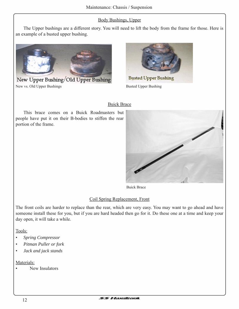
Body Bushings, Upper
New vs. Old Upper Bushings Busted Upper Bushing
The Upper bushings are a different story. You will need to lift the body from the frame for those. Here is
an example of a busted upper bushing.
The front coils are harder to replace than the rear, which are very easy. You may want to go ahead and have
someone install these for you, but if you are hard headed then go for it. Do these one at a time and keep your
day open, it will take a while.
Tools:
• Spring Compressor• Pitman Puller or fork• Jack and jack standsMaterials:
• New Insulators
Buick Brace
Coil Spring Replacement, Front
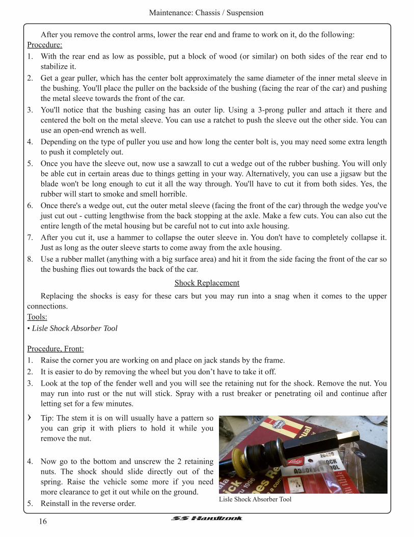
Buick Brace
This brace comes on a Buick Roadmasters but
people have put it on their B-bodies to stiffen the rear
portion of the frame.

1 3SSHandbook
Maintenance: Chassis / Suspension
Coil Spring Replacement, Rear
These are MUCH easier than the fronts.
Tools:
• Spring Compressor• Pitman Puller or fork• Jack and jack standsMaterials:
• New InsulatorsProcedure:
1 . Raise the vehicle by the axle and place jack stands under the frame.
2. Leave the jack in place, lower the axle until it is at rest, and stop.
3 . There should be enough room to simply pull the spring out by hand but if there isn’t then remove the
bottom of the shocks by unscrewing the nut on the end of the lower control arm and lowering the axle a
little bit more.
4. Use a piece of tape to hold the new insulators in place while you put it back in.
5. Make sure the spring are set in the holders attached to the axle and not blocking the little drain hole.
6. Reinstall the nuts on the shocks if needed and raise the vehicle back up off the jack stands.
7. Remove the stands, lower the car, sit back and enjoy!
Procedure:
1 . Jack up the corner you’re working on and place it on jack stands by the frame, you’ll need the jack for the
spring install.
2. Remove the shock. See Shock Replacement.
3 . Remove the wheel and disconnect the lower part of the spindle and sway bar end links.
4. Use your spring compressor to compress the spring. Now place your jack under the control arm to brace it
and remove the bolt on the ball joint. Use your special tool and break the ball joint loose.
5. Lower the control arm and remove the spring.
6. Compress your new spring and install the new insulator on top & bottom. A piece of tape will hold them
on b/c without it, the insulator will get misaligned and cause squeaking later.
7. After it is in place, raise the control arm back up and reinstall in the reverse order.
› WARNING!!! There is a possibility that the spring may slip while doing this. Catching a face full ofspring will cause serious injury if not worse! ! !

14SSHandbook
Maintenance: Chassis / Suspension
Rear Control Arm Replacement
Tools:
• Jack and jack stands
• Sockets and Ratchet
• Wrenches
Well, the lowers are very simple and the uppers are easy to remove as well, but the main thing you need to
be concerned with is the alignment of the axle. DO NOT remove all arms at the same time. Go one by one, so
it will be easier to reinstall the arms. You will likely have an adjustment to be done to get the bolts to line up
but it shouldn’t be more than nudge to the rear tires here and there.
Before starting to replace either the uppers or lowers, you’ll need to decide if you want to remain stock or,
if you want to get extended and center the rear wheels. Remember to select what brand you need. Also, don’t
forget that stock arms are okay but if you are going to use aftermarket arms, the extended arms may be a
better choice. See Preferred Brands, Control Arms.
Now, when choosing extended or stock length, please keep in mind a couple of different things. The
change does not help you any as far as performance, except maybe a longer stance and slightly better handling
but no one has ever said it was noticeable. The main purpose is to center the rear wheels. If you haven’t
noticed already, the rear wheels sit a little forward in the wells. Some don’t like this look and some don’t care.
If you decide to go with extended arms, there are other issues. One is maybe getting a new driveshaft, or
you can get a longer yolk, with getting a longer driveshaft being the better option. It will work for a while if
you change neither, but the seal to the transmission will grow weak and soon you will be wishing you took
more time researching this procedure.
Rear Control Arm Replacement, Lower
Procedure:
1 . First, chock the front wheels and lift the rear of the
car by the differential, then place jack stands under
the frame. Lower the jack, until the axle is at rest,
then lift back up a little and support the axle with
the other two jack stands. It is important you
support the axle in its normal position.
2. The lowers are a cinch. Remove the sway bar,
unbolt and replace the arms one at a time. See Sway
Bar Replacement.
Lower Rear Control Arms from UMI Performance

1 5SSHandbook
Maintenance: Chassis / Suspension
Rear Control Arm Replacement, Upper
Procedure:
1 . The uppers are the same way but the bolts
connecting the arms to the body are difficult to get
to and are large, maybe 21 or 22mm. You’ll need a
socket in that size as well as a wrench to hold the
nut. Removing those bolts from the holes is
somewhat difficult but a few whacks of a hammer
and they’ll come out. If you flatten the threads,
don’t worry, the new arms come with new bolts but
just check to be sure before starting.
Now, the hardest and most time-consuming part of
the replacement is the bushing removal. If you don’t
have a bushing removal tool like the one pictured here.
Rear End Bushing Removal
Background:
When removing the control arms, there's no need to disconnect the brake lines and therefore, no brake
bleeding.
Upper Rear Control Arms from UMI Performance
This is definitely one of the times where the old saying “the right tool for the right job” applies.
Follow the rear end bushing removal instructions inserted below. It’s recommended to use a bushing
removal tool because you tend to beat the mess out of the new bushing if not. Also, when you use the puller to
remove the shaft from the middle of the bushing, use a bolt laying around and drill an indention in the tip and
let the bolt do the pushing and not the tip of the puller bolt. You don’t want the place you rented it from, or
yours, to get damaged.
Safety:
1 . Jack up the car as high as possible, chock the front wheels and put jack stands under the car.
PLEASE TAKE ALL SAFETY PRECAUTIONS AS YOU WILL BE UNDER YOUR CAR FOR AWHILE.
2. Remove the bolt holding the brake line to the axle
housing (at the top of the diff).
3 . Open the tabs along the housing to detach the brake
lines from it.
4. While lowering the axle, bend the lines down for
more slack. Be careful not to put and kinks in the
line. Bend it smoothly and evenly.
5. Installation is the reverse.
Tools:
• Gear puller• Sawzall or Jigsaw (Sawzall is preferred)• Rubber mallet• Hammer Bushing Tool from HR Parts N Stuff
16SSHandbook
Maintenance: Chassis / Suspension
Shock Replacement
Tools:
• Lisle Shock Absorber ToolProcedure, Front:
1 . Raise the corner you are working on and place on jack stands by the frame.
2. It is easier to do by removing the wheel but you don’t have to take it off.
3 . Look at the top of the fender well and you will see the retaining nut for the shock. Remove the nut. You
may run into rust or the nut will stick. Spray with a rust breaker or penetrating oil and continue after
letting set for a few minutes.
Replacing the shocks is easy for these cars but you may run into a snag when it comes to the upper
connections.
After you remove the control arms, lower the rear end and frame to work on it, do the following:
Procedure:
1 . With the rear end as low as possible, put a block of wood (or similar) on both sides of the rear end to
stabilize it.
2. Get a gear puller, which has the center bolt approximately the same diameter of the inner metal sleeve in
the bushing. You'll place the puller on the backside of the bushing (facing the rear of the car) and pushing
the metal sleeve towards the front of the car.
3 . You'll notice that the bushing casing has an outer lip. Using a 3-prong puller and attach it there and
centered the bolt on the metal sleeve. You can use a ratchet to push the sleeve out the other side. You can
use an open-end wrench as well.
4. Depending on the type of puller you use and how long the center bolt is, you may need some extra length
to push it completely out.
5. Once you have the sleeve out, now use a sawzall to cut a wedge out of the rubber bushing. You will only
be able cut in certain areas due to things getting in your way. Alternatively, you can use a jigsaw but the
blade won't be long enough to cut it all the way through. You'll have to cut it from both sides. Yes, the
rubber will start to smoke and smell horrible.
6. Once there's a wedge out, cut the outer metal sleeve (facing the front of the car) through the wedge you've
just cut out - cutting lengthwise from the back stopping at the axle. Make a few cuts. You can also cut the
entire length of the metal housing but be careful not to cut into axle housing.
7. After you cut it, use a hammer to collapse the outer sleeve in. You don't have to completely collapse it.
Just as long as the outer sleeve starts to come away from the axle housing.
8. Use a rubber mallet (anything with a big surface area) and hit it from the side facing the front of the car so
the bushing flies out towards the back of the car.
Lisle Shock Absorber Tool
› Tip: The stem it is on will usually have a pattern so
you can grip it with pliers to hold it while you
remove the nut.
4. Now go to the bottom and unscrew the 2 retaining
nuts. The shock should slide directly out of the
spring. Raise the vehicle some more if you need
more clearance to get it out while on the ground.
5. Reinstall in the reverse order.

17SSHandbook
Maintenance: Chassis / Suspension
Procedure, Rear:
1 . Raise the vehicle by the axle and place jack stands under the frame.
2. Leave the jack in place, lower the axle until it is at rest, and then raise it back up just a hair.
3 . If you have another set of jack stands, you can put those under the axle while doing this, but if not a jack
will do fine.
4. Remove the nuts at the bottom of the shock and slip it off the lower control arm.
5. Now, here is the tricky part. The more room you have, the better it will go. Remove the wheel and the
spring. See Coil Spring Replacement.
6. Okay, two bolts hold the top in. Only one needs to be completely removed. The shock bracket has two
sides, one is a complete hole and the other is a crescent so it will slide from around the bolt. Which one is
it? Only you will know.
7. Use a LONG extension to your socket wrench to reach the bolts and use a small wrench to get to the get
to the top side. You will be working blindly getting on the nuts on the top but be patient and you’ll get it.
8. Reinstall in the reverse order. Usually people will turn the bolts around for the top part of the shock so it
will be easier reinstalling them. Truth is, GM should have tack welded the nuts into place when they built
the car. The most important thing to remember is to be patient through this process.
Sway Bar Replacement, Front
Procedure, Front:
1 . Raise the vehicle and place jack stands under the
frame.
2. Remove the end links that connect the sway bar
ends to the spindle, but keep track of the order of
the bushings and washers in case you are reusing
your old ones.
3 . Remove the four bolts that attached the brackets to
the frame (two in each bracket). Be careful, the
sway bar is heavier than it looks so don’t let it fall on your face!
4. Reinstall in the reverse order. If you use urethane bushings, you can grease them up to lengthen their life
and reduce squeaking.
Procedure, Rear:
1 . Raise the vehicle by the axle and place jack stands under the frame.
2. The sway bar is held on by 4 bolts to the lower control arms, 2 to each side.
3 . Remove the bolts and don’t let the sway bar hit you in the face! Remember, it is heavier than it looks!
4. Reinstall in the reverse order.
When you finish, take your beast for a ride. You WILL notice a difference.
› Remember, to fully optimize your new sway bar, get new bushings and/or end links when replacing. They
are around $16-$20, purchased at your favorite parts store.
Front and rear sway bars.

18 SSHandbook
Maintenance: Cooling System
Tools:
• Flat head screwdriver• Rags and bucket• Clear Hose (not required)
Park your car where the rear is lower than the front
if possible or even jack up the front end. The point is to
get the bleed valve higher than the heater core. Let the
engine cool preferably overnight. Slightly open the
bleeder screw and let the air out. This may take a couple
of tries but once all of the air is out, no more waterfall
sound.
Another popular mod is to install a quarter turn ball
valve (1 /8-27 thread) and a barb in place of the original factory bleeder assembly (two-piece bleeder bolts).
See. Attach a length of clear tubing, to see the bubbles, that will reach over to the coolant overflow tank or
another suitable container. With this mod, it is easier to bleed the air out of the system without worry of
coolant getting on the opti-spark or spillage. After bleeding, the hose should be replaced by a cap to help keep
the barb fitting clean.
1 /4 Turn ball valve with hose barb and clear tubing.
Cooling System
Bleeding The System
Here is a great way to change the anti-freeze / flush the system and not get the dreaded waterfall noise.
Tools:
• Socket wrench• Flat head screwdriver• Rags and bucket• AntifreezeIMPORTANT!!! If your car is hot, do not pump cold water into the motor! Let the engine cool first! We will
not be held responsible for someone cracking their block or head because they were impatient.
Procedure:
1 . Place an appropriate sized container under the car to catch any spilled coolant.
2. Remove the plastic resonator on top of the motor (Home Plate) as well as the resonator between the air
box and home plate (First Base) if you haven’t deleted them already. See Home Plate Removal and First
Base Removal for more detail.
3 . Take the overflow breather off and let it drain into a bucket. This will siphon a 1 /3 of the anti-freeze out of
the motor.
4. Remove bottom hose to drain radiator. If you don't want to drain radiator skip to step five.
Flushing The Radiator

19SSHandbook
Maintenance: Cooling System
5. Put bottom hose back on and remove the top hose near the air box.
6. Start car and let it push the remainder of the coolant out of the system. Using a hose run water into the
overfill container. It will suck it into the motor about as quickly as the garden hose can fill it. Continue
doing this until you see no more coolant come out. You might want to cycle the heat on to get water
through the heating core. It might take a little bit for the thermostat to open but when it does all the old
gunk and coolant comes out. When finished, thoroughly wash off all of the anti-freeze off the front of
your car. That stuff can't be good for the paint.
7. When all the old coolant is gone, stop putting water into the overflow tank. Let the motor pump dry.
When the water starts to surge out of the hose shut her down. You still have about 2 gallons in the system.
8. Put all the hoses back on tightly, and start to fill the overflow container with straight anti-freeze.
Remember there is still 2 gallons ofwater in the motor.
9. Start motor and let it suck everything in through the overflow. When it won't take anymore and the stat
has opened (top hose will be warm) then open the bleeder valve going into the thermostat. See Bleeding
the System.
10. Put the resonators back in place on the motor, if you are using them, and make sure all hoses are on and
tight. Do not forget the little overflow hose.
11 . Keep adding until you are at the cold fill mark and go drive for a few days. Top off some morning to the
cold fill and you are done.
Heater Core Flush
Tools:
• Socket wrench• Flat head screwdriver• Rags and bucket• BucketProcedure:
1 . Put a bucket or pan beneath and slightly ahead of the serpentine belt tensioner. You may have to readjust
the bucket once the draining starts.
2. Disconnect heater core hoses at the water pump. These are the two smaller hoses facing the passenger
side, towards the battery. The lower hose and pipe will dump a bunch of coolant out of the engine into the
bucket. Be sure it doesn't get all over the opti-spark behind the crank damper.
3 . Take a garden hose, put it up against the lower hose, and run until it goes clear. Soon people believe that
getting bubbles in the flow will help clean everything out.
4. Now switch to the pipe and back flush.
5. Repeat spraying water into the lower hose until the heater core water runs clear or it hacks up a hairball.
6. Repeat Steps 3-5 a few times to be sure you’ve cleaned everything out of the system.
7. Reassemble cooling system, fill up the expansion tank and screw the cap on.
8. Bleed the system.
9. At this point, the heater should start getting hot. Repeat until you've replaced all of the coolant you lost.
› BTW - keep the rest of the cooling system closed up when you do this. Do not try to be slick and hook a
hose to your bleeder valve, open the reservoir cap and dump the extra fluid back in. It is self-defeating.
Just open the bleeder valve and put a rag or paper towel next to it; leave it cracked open a turn until
coolant starts coming out, then close it up. Drive around for a few heat cycles, repeat.

20 SSHandbook
Maintenance: Cooling System
Temperature SSensor Replacement
Tools:
• Socket wrench• Adjustable wrench
There are two different sensors. There is one on the water pump which sends readings to the PCM, and
there is one in the passenger’s side manifold that sends reading to you gauge on the dash.
Both sensors can be unscrewed with a crescent wrench but it is recommended that you use a deep socket.
Both of these sensors may also be replaced at the same time as the water pump is without the need to worry
about coolant leaking.
Water Pump Sensor
The water pump sensor is simple to replace. Simply unscrew the sensor from the water pump after
disconnecting the electrical connector. Have the new one ready with Teflon tape on the threads and install it
when the old one is removed. Coolant will leak so have some rags or bucket handy to catch any leaking
coolant.
Manifold Sensor
This one is more difficult and the most common cause of gauge problems. Raise the vehicle, and feel
around the middle of the engine around the headers. Do this when the car is cool. The sensor will be covered
in a heat resistant silver coating to repel heat. Pull back the wrapping and disconnect the sensor harness.
Slowly unscrew the sensor until loose enough to finish it by hand. Coolant will come out of this hole pretty
fast so you will need to be quick and do not have your face looking directly up at the sensor or you will regret
it. Once you get the sensor out, quickly install the new one, wipe off any excess coolant and reconnect the
sensor.
Thermostat Replacement
Tools:
• Socket wrench• Flat head screwdriver• Rubber mallet• Rags and bucket• Pliers• New screw driven hose clamp for larger hose• Siphon tool (not required)Procedure:
1 . Remove Home Plate and First Base. See Home Plate Removal and First Base Removal for more detail.
Once you have everything off, you will see the gooseneck coming out of the water pump. Your thermostat
is underneath that neck.
2. Release the petcock at the bottom of the radiator on the driver’s side to lower the level of coolant to
prevent a lot of spillage. Not too much, just a little will do.
3 . Now remove the hose clamp from the upper radiator hose leading into the water pump (you will need
pliers for the original clamp). Before you remove the hose, have some rags and/or a bucket to contain the
spillage.

21SSHandbook
Maintenance: Cooling System
4. Slowly pull off the hose. It may be stuck on it but a good twist will loosen it. When the hose gets loose,
stick the end in the bucket or rags whichever you have handy. Stuffing a rag in the end of the hose will
prevent coolant from dripping out.
5. Now for the gooseneck, you can look into the gooseneck and see coolant and the thermostat. Use rags or a
siphon to get out the coolant around it.
6. Use a wrench to loosen the bolts of the gooseneck. If the gooseneck is stuck, then tap it with a mallet to
break it loose.
7. Remove the thermostat and O-ring, and remove any old gasket material from the lip.
8. Install the new one with a new gasket.
9. Proceed in the reverse order.
1 0. After you replace everything, replace the coolant you drained or siphoned with new coolant. See Bleeding
the System .
› Tip: This is a good time to replace any hoses that are cracked or deteriorated
› Tip: It is recommended to flush the radiator if it hasn’t been done recently.
› Note: You can replace the stock thermostat (1 80-degree) with an aftermarket 160-degree thermostat. It
will cause the engine to run cooler but will take the heater longer to warm up in the winter. Some say
there is no difference without PCM reprogramming or you must have the PCM reprogrammed. Wrong.
The thermostat is not controlled by anything but temperature. If you have the PCM reprogrammed, then
the 160-degree thermostat will be more effective combined with the fan temperature settings.
Water Pump Replacement
Tools:
• Socket wrench• Flat head screwdriver• Rags and bucket• Antifreeze
Replacing the water pump is not too difficult. First, you will need to drain the cooling system. Now is a
good time to replace any hoses that need replacement as well as the thermostat or even upgrade to a 160°
thermostat. Before you begin, cover the opti-spark with some plastic or towels to protect it from coolant
because it will damage your opti-spark.
Procedure:
1 . See Flushing the Radiator; Steps 1 -5.
2. Put a towel/rag under the waterpump and on top of the opti to protect it from any coolant that will spash
on it. Antifreeze in opti = sad opti = $$$ = you not happy. In fact don't get coolant anywhere except in the
bucket. If you get it on the paint wipe that stuff offwith the quickness!
3 . Disconnect the hoses from the water pump.
4. Remove your AIR pump and harness and the serpentine belt.
5. Remove the six (6) bolts from the water pump and gently work it free. Now when you pull the pump off,
pull it towards you, not down or it will damage the splined shaft behind it. Watch out there will still be
fluid coming out so make sure you DO NOT get it on the opti-spark. Also, watch out for the splined
coupler.

22 SSHandbook
Maintenance: Cooling System
6 Remove the thermostat housing (on top of the waterpump) and thermostat. Put these in the new
waterpump. DO NOT OVERTIGHTEN THE BOLTS. The FSM says 20lbs of torque, this is incorrect, it
should be 8lbs. If you start leaking from here after all is said and done you can tighten them down a bit
more but DO NOT STRIP THE THREADS ON THE WATERPUMP.
7. Clean off all remnants of the old gaskets.
8. Now is a good time to replace the water pump drive seal. Use a pick and remove the old one. Install the
new one using extreme care not to damage the seal around the shaft. A tool can be found on the forum
that helps with installation.
9. Place the new gaskets. You need sealant on both sides of the gaskets.
1 0. Place the splined coupler on the shaft mounted to the cam.
11 . Reinstall everything in reverse order.
1 2. Torque to 30 ft-lbs.
1 3 . Fill the system and drive the car until it warms up.
14. Let it cool, but is still warm.
15. Refer to “Bleeding The System”.
16. Let car sit for several hours
17. Repeat steps 1 3 - 16.
1 8. Look for leaks, smell for antifreeze (you may smell some from have it dripping everywhere but it should
go away in 24 hours unless you dumped it everywhere).
› Weep Hole Tip: For the weep hole on your water pump. Get a 1 /8" NPT (National Pipe Thread) tap and
run a thread in the weep hole. Be sure to use cutting oil and keep the tap straight. Also be sure to clean out
all of the chips from the water pump. Then get a barbed fitting and run a short piece of tubing. If the water
pump goes, it won't drip on your opti-spark.

23SSHandbook
Maintenance: Electrical
Electrical
Headlight Instrument Panel Illumination
If the light goes out in your Headlight Instrument Panel, you have a choice to make. You can do it the easy
way by buying a Honda bulb, changing the bulb itself, or the hard way paying for a completely new
panel. If you've ever changed the mini bulbs out of Christmas tree lights (pre-LED) this will be a cinch. If
not, then read carefully before beginning just to get an idea.
Tools:
• 7mm socket with screwdriver handle• Jeweler's flathead screwdriver (or mini flathead)• Tweezers• Wire cutters or scissors
Materials:
• Radio Shack lamp # 2921092 (2 per package)OR
• Replacement bulb P/N# 35505S84B02 (From Honda of all places)Procedure:
1 . Remove the cluster bezel screws and lower dash screws (7mm socket).
2. After removing the cluster bezel and lower dash, remove the bottom screw (7mm) from the switch
assembly, if present.
3 . Once removed, pull the switch panel out. Peel back the black plastic tape on top of the switch to reveal
the light bulb holder. It is the size of a shirt button.
4. Use a flathead jeweler's screwdriver (or mini-flathead) twist it to the left about a quarter turn.
5. Use a pair of tweezers to lift it out of the switch.
6. If using the Honda bulb Skip to step 10. If using the Radio Shack bulb continue. Take the bulb holder to a
table and sit down.
7. Look at all the sides of the holder, you will notice the bulb wires come out of the top, and wrap around the
sides, across the bottom of the holder and end in the sides going to the top edge.
8. Use either the tweezers or screwdriver to undo the wire from the grooves in the bulb holder. Straighten
them out and pull the bulb out from the socket.
9. Thread the new bulb in, and thread each wire into the grooves in and around the bottom of the holder,
finishing with the top. Use cutters to trim the excess wire. The bottom of the holder should have the wires
across to make contact with the switch receptacle.
1 0. Put the bulb in, twist to the right a quarter turn.
11 . Put your key in and turn the switch to the RUN position. The bulb should illuminate and be seen thru the
plastic.
1 2. Turn the key to OFF, place the black tape back over it.
1 3 . If the tape is no good, use black electrical tape instead.
1 4. Put switch back in and reassemble dash. The bulb should last many years.
1 5. Keep the extra bulb in a safe place if you ever need to replace it-or give it to a buddy for his B-Body.

24SSHandbook
Maintenance: Electrical
Opti-Spark Installation
› When replacing the opti-spark, add the weep hole fitting.
Procedure:
1 . First, disconnect your battery.
2. Drain your coolant. Be sure to open the bleed screws. This will help it drain much quicker.
3 . Remove the rubber intake elbow.
4. Remove the upper radiator hoses.
5. Disconnect the bottom radiator hose from the water pump.
6. Remove the coil wire, and the electrical connections from the Opti-spark and water pump.
7. Pull the belt tensioner out of the way, and loosen the accessory belt.
8. Remove the water pump. See Water Pump Replacement
9. Check the weep hole on the water pump to make sure it's not damp.
10. This is the fun part (for me at least). Remove the three bolts from the balancer. Use a gear puller to do
this. MAKE SURE you make a note of the position of the balancer in relation to the hub. Both the hub
and balancer should be marked, but not keyed.
11 . Remove the remaining plug wires. If they are old, you may want to replace them. Now is the time to do it!
1 2. Remove the three bolts that hold the Opti-spark in place. Pull it straight out. There is a shaft, which
connects the Opti-spark to the Cam gear. This may or may not come out with the Opti-spark. At this point,
you should look at the old Opti-spark and make a mark ofwhere the notch (spline) is. This will assist you
later.
1 3 . This would be a good time to put some gasket sealant on one side of the gaskets, and place them on the
water pump so they can dry. This will make reinstalling the water pump much easier.
1 4. With the old Opti-spark to compare, rotate the shaft on the new one until they match up. Some find it
easier to insert the shaft on the camshaft, and then sliding the Opti-spark on top of it.

25SSHandbook
Maintenance: Electrical
1 5. If there is any gap on any of the three mounting screws, you probably haven't lined the Opti-spark up
correctly with the spline on the shaft. It should slide all the way on with no gaps on any of the mounting
areas. Tighten the bolts, but do not over tighten.
1 6. Run your vacuum lines. The clip goes on the alternator bracket. MAKE SURE the hoses are going to clear
the belt. The hose that has the filter and regulator is the vacuum supply. Poke a hole in the rubber bellow
(on the top) and push the L into it. Put a T or something similar on the driver’s side intake manifold, and
hook the vacuum hose up.
1 7. Reconnect the plug wires.
1 8. Reinstall the three bolts on the balancer. Tighten the bolts to 60 ft-lbs. Make sure you line it up properly
(see step above where you removed it).
1 9. Put gasket sealant on the remaining gasket material, and reinstall the water pump. Tighten to 30 ft-lbs.
20. Reinstall the belt. It is much easier to do it now before you do the next step!
21 . Reconnect all the hoses, the coil wire and the other misc electrical connections (temperature sensor, Opti-
spark connector, etc).
22. Lightly tighten the bleed screws.
23. Refill the cooling system until it is full. Place a rag around the bleed screws, and bleed off the excess air.
Don't let any coolant get on your new Opti-spark!
24. Check and recheck everything.
25. Fire it up.
› You should also pull the hose out of the bellow, and check for vacuum. If it gets clogged, or a hose gets
pinched, it will cause the cap to cave in, and burn up the rotor.
Opti-Spark Conversion
From 1992 - 1994 the Opti-spark was what is known in the gearhead world as "unvented". The reason it is
called this is because it does not have the vacuum hoses connected like the newer 1995+ LT1 /LT4 engines
have. What the vacuum hoses do is, they pull the moisture out of the Opti-spark.
What a lot of people don't realize is the unvented Opti-sparks are actually vented! ! Yes, they have 3 weep
holes at the base of the Opti-spark to allow moisture to escape. Well, all this does is pull moisture back in. Put
cold water on a hot Opti-spark, it's going to suck the water in! This is the BIGGEST problem with the design.
Before you go out and buy a brand new 1995+ Opti-spark, be forewarned. You CANNOT bolt a 1995+
Opti-spark up to a 1992-1994 LT1 . The CAM is different. You could change the CAM, timing cover, CAM
gear, etc. but this gets expensive, and is very labor intensive.
So, what is the solution? You can do 1 of 2 things:
Option 1 : Change the Opti-spark out and be up and running again. However you risk damaging it again. There
have been people who have had to replace a brand new Opti-spark because they got them wet.
Option 2: Change the Opti-spark out with a modified unit.
The conversion process is simple!

26SSHandbook
Maintenance: Electrical
Buy an older style Opti-spark (the one you're supposed to buy), and simply change the cap! Of course,
you will need to do a few additional things.
Parts:
• Optispark for 19921994 LT1's PN 10457702• Cap and Rotor kit PN 10457735 or• 1995+ Distr. rebuild kit (Pep Boys or NAPA)• 1996 Vacuum Hose Kit PN 12556174 or• 1995 Vacuum Hose Kit PN 12555323Tools:
• Inverse Torx Bit E4, deep well!! SnapOn part number STLE40. Stop a truck, or order online atwww.snapon.com
• 2claw puller• 2 water pump gaskets• Gasket sealant• Vacuum T or a brass T that will screw into the manifold• Long Breaker bar, or torque wrench• Brass fitting for the base of the Optispark.• 3/16" Drill Bit (slightly bigger than the hole your drilling out)
Recommended:
• Plugs and Plug WiresProcedure:
1 . Remove your cap from your new Opti-spark. Nothing like taking apart something brand new eh?
2. Remove the rotor from the Opti-spark. This should be a Torx T15. Carefully remove the rotor, and the
metal disc. Do NOT remove the slotted one! Its spot welded on for a reason. Only the disc directly behind
the rotor should be removed.
3 . Remove the middle spacer. This is the center portion of the Opti-spark body. Set aside everything, but the
back plate. Be careful when handling this. Try not to get any grease, dirt or anything on the disc.
4. You will notice 3 holes on the base. Fill the center one, and the one closest to the long pointed portion of
the base in with JB Weld or something similar. Drill out the remaining hole. Try not to get the metal
shavings in or on the Opti-spark.
5. Next, tap in a brass fitting. Do not use the center hole for this, as it won't clear the balancer hub. If you
can find a brass L fitting, this would be your best bet.
6. Vacuum the metal shavings from the previous step. Make sure it's clean before you put it back together.
7. Reassembly is the same. Make sure you don't forget to put the metal disc back in place. If you leave it out,
the gap for the rotor and cap will be way off. The rotor and disc are keyed, but still be sure you put them
in correctly.
› Remove the old RTV Sealant, and put some new RTV on the cap at the electrical connection. Put it back
together with the newer style cap. Lightly blow into one of the hose connections while closing off the
other. You should hear no hissing. Also don’t allow the shaft to spin on the Opti-Spark.

27SSHandbook
Maintenance: Electrical
Plug and Wire Change
Tools:
• Floor jack• quality jack stands• Lug wrench and locking lug nut socket.• Flathead screwdriver• 3/8" drive ratchet• 3/8" extensions of different lengths. Recommended sizes 4",6", 12", and 18"• "regular" 5/8" plug socket, only necessary if you have headers• 3/4" openend wrench (or whatever size appropriate for the above socket)• "Ujoint" 5/8" plug socket, 3/8" drive• Set of metric 3/8" drive sockets, preferably deep well• 3/8" Ujoint• Wire cutters• Needle nose pliers• Dremel Tool with cutoff wheel (only if you have headers)• A couple 34 foot lengths of 1214 gauge insulated wire• Flashlight with GOOD batteries• Masking Tape• Ink PenMaterials:
• A good set of spark plugs and plug wires.• Antiseize compound• Dielectric greaseInitial Procedure:
• Remove center caps, loosen front wheel lug nuts• Set the emergency brake and put chocks under the rear wheels.• Jack up the front of the car, place on jack stands and remove the wheels.• Check the gap of the plugs (stock is 0.050"). Also, put a thin layer of antiseize on the plugs before install.
Doing this will keep the threads from seizing to the head, and make later removal MUCH easier.• FYI, the plugs are numbered 1,3,5,7 (from front to back) on the driver's side and 2,4,6,8 (from front to
back) on the passenger side.

28SSHandbook
Maintenance: Electrical
Changing Plugs, Stock Manifolds
Plug Procedure:
1 . ALL EIGHT plugs are accessible thru the wheel wells. No one believes this until they try this, then they
won't do it any other way!
2. Starting on the driver's side, working back (plug 1 ), simply unplug the plug wires and use the 3/8" ratchet,
a couple of the long extensions, and the u-joint plug socket to remove and replace the first plug. Go
THRU the wheel wells.
3 . Continue this, working from front to back. Once done with driver's side, repeat on passenger side
Would you rather try it from the wheel well this way.. . . . .or from the top like this?
A shot without manifolds or headers.

29SSHandbook
Maintenance: Electrical
Plug Procedure:
› Note that this procedure is based on Clear Image Automotive Tri-Y Headers, so the info will be somewhat
specific to them but, will apply to other headers
1 . For plugs 1 and 3, it is easiest to just do them from up above. These plugs are possibly EASIER with
headers than with stock manifolds!
2. Plug 5 is a bit of a bear. To do it, you need to take the "regular" sparkplug socket and modify it (with
Dremel tool and cutoffwheel, hacksaw, or however else you wanna do it), cutting approx 3/4" off the end
of the socket. This will let it JUST clear the header tube (the socket, unmodified, will NOT clear the
header tube). You will also need to remove the rubber "tubing" inside the plug socket, and shorten it about
the same amount (use wire cutters or something else appropriate here). Once modified, you can then slip
the modified socket onto the plug and use the 3/4" box-end wrench to turn the socket and loosen it. Once
"broken loose" a little, you can complete removal by hand. To reinstall, start the plug by hand and once it
is "hand tight" you can slip the modified plug socket back on the plug and go from there.
3 . Plug 7 is the same as with stock manifolds (thru the wheel well).
4. Plugs 2, 4, 6 are easiest thru the wheel wells, same as stock manifolds.
5. Plug 8 is another bear. Once again, put on the modified plug socket. Then, from UNDER the car, slip the
3/4" box end wrench up and on the plug socket and loosen it up. With the headers, there will be enough
room between the header collector and the engine block to get your hand with a wrench up there. Install
the new plug similar to #5 (by hand, then tighten with the socket and wrench).
Changing Plugs, Headers
30SSHandbook
Maintenance: Electrical
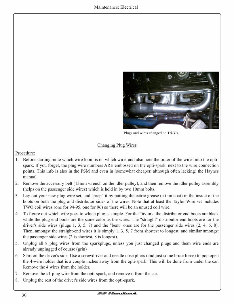
Changing Plug Wires
Procedure:
1 . Before starting, note which wire loom is on which wire, and also note the order of the wires into the opti-
spark. If you forget, the plug wire numbers ARE embossed on the opti-spark, next to the wire connection
points. This info is also in the FSM and even in (somewhat cheaper, although often lacking) the Haynes
manual.
2. Remove the accessory belt (1 3mm wrench on the idler pulley), and then remove the idler pulley assembly
(helps on the passenger side wires) which is held in by two 10mm bolts.
3 . Lay out your new plug wire set, and "prep" it by putting dielectric grease (a thin coat) in the inside of the
boots on both the plug and distributor sides of the wires. Note that at least the Taylor Wire set includes
TWO coil wires (one for 94-95, one for 96) so there will be an unused coil wire.
4. To figure out which wire goes to which plug is simple. For the Taylors, the distributor end boots are black
while the plug end boots are the same color as the wires. The "straight" distributor-end boots are for the
driver's side wires (plugs 1 , 3, 5, 7) and the "bent" ones are for the passenger side wires (2, 4, 6, 8).
Then, amongst the straight-end wires it is simply 1 , 3, 5, 7 from shortest to longest, and similar amongst
the passenger side wires (2 is shortest, 8 is longest).
5. Unplug all 8 plug wires from the sparkplugs, unless you just changed plugs and them wire ends are
already unplugged of course (grin)
6. Start on the driver's side. Use a screwdriver and needle nose pliers (and just some brute force) to pop open
the 4-wire holder that is a couple inches away from the opti-spark. This will be done from under the car.
Remove the 4 wires from the holder.
7. Remove the #1 plug wire from the opti-spark, and remove it from the car.
8. Unplug the rest of the driver's side wires from the opti-spark.
Plugs and wires changed on Tri-Y's.

31SSHandbook
Maintenance: Electrical
9. For the rest of the driver's side plugs, I found it easiest to just remove the entire metal bracket that holds
the wires (little holders, plus holds the #7 wire tight against the block) against the engine block. It is held
on by two 10mm (I think) bolts, and at least with my car with the headers I could get to both bolts thru the
wheel well with some socket extensions and u-joint.
1 0. Loosen the two bolts above, and remove the bracket from the car. It has JUST enough room to slide out
the front, past the AIR pump.
11 . Once the bracket is removed, it is a LOT easier to individually remove/replace the wires from the bracket.
Just match up the wires, and get them back into the bracket with approx the same lengths on each side of
the 3 and 2 wire holders as the stock wires had. Also swap over any wire look from the old wires to the
new wires, or replace with appropriate length/diameter of new loom.
12. Reinstall the bracket assembly, with the 3,5,7 plug wires installed in it. Reinstall the two 10mm bolts that
hold the bracket to the block.
1 3. Plug the #3,5,7, wire boots onto the plugs, feeling for a "snap" that confirms the wire boot is tight on the
plug.
1 4. Reinstall the #1 plug wire onto the plug, and route the other end of the wire down with the 3,5,7 wires to
the 4-wire holder.
1 5. Reinstall the wires into the 4-wire holder, and snap it tight. Reinstall rest of the loom pieces (or new ones)
onto the wires.
1 6. Plug the wires onto the appropriate places on the opti-spark (once again, plug wire numbers are embossed
on the end of the opti-spark).
1 7. Now to the "fun" side (grin). Slide over to the passenger side, and unplug the wire boots from the opti-
spark. It works a LOT better if you start with the "top" one (wire 4) and work your way down to the
bottom (wire 2).
1 8. Cut the opti-end boots off the plug wires. Trust me on this one!
1 9. Working from the motor side (mostly thru the wheelwell, some underneath), pull the old wires out from
the plug ends. This is a LOT easier than ANY other way on these wires.
20. Collect all the pieces or wire loom that fell off the wires as you removed them in the above step.
21 . With the wires NOT in them, it is MUCH easier to unsnap the wire holders. Unsnap the 4-wire holder
(near the distributor), 2 wire holder that held wires 6,8 (approx below the #4 plug), and the 1 wire holder
that held wire 8 (approx below plug 6).
22. For the 4 passenger side wires, LABEL the opti-spark boot ends!
23. On the passenger side, the easiest way to route the plug wires into place is to tie the 12 gauge wire (see
the "tools" section) around the plug boot end of the wire, and route the 12 gauge wire up thru the space
between the accessory bracket and the AC compressor where the plug wires are squeezed thru. You can
much more easily push this "stiff" wire up thru the spaces than the "limp" sparkplug wires.
24. Start with the #8 wire, tie the 12 gauge wire to it and push it up and thru. Eventually, the 12 gauge wire
will pop out near the #6 plug (can be seen from underneath) and you can use the wire to pull the plug wire
thru to the #8 plug. Untie the #8 wire from the 12 gauge wire, and snap the boot onto the #8 plug. Then,
put a piece of loom onto the #8 wire (with the loom between the plug boot and the 1 -wire holder), and
snap it into the 1 -wire holder below the #6 plug. Making sure there is a little (but not much) slack in the
#8 wire, snap the 1 -wire holder closed. Be sure you have things right, as it is a beast to get this 1 -wire
holder back open if there is a wire in it!
25. Also put the #8 wire into the 2-wire holder, but DO NOT snap it shut yet!
26. Next, route the #6 wire up and thru with the 12 gauge wire, similar to how you did the #8. Snap the #6
boot onto the plug, and put it (with a little, but not much) slack into the 2-wire holder. Once you are

32SSHandbook
Maintenance: Electrical
SURE that things are right, go ahead and snap shut the 2-wire holder.
27. Put a piece of loom on each of the #8 and #6 wires forward of the 2-wire holder (i.e. on the parts of #8
and #6 wires that are running below the #4 and 2 plugs).
28. For the #4 wire, you wanna tie a piece of 12 gauge wire to BOTH ends of the plug wire. Route the plug
boot end up as you did with #6 and #8, but you'll probably have to "overshoot" to get the boot far enough
down to untie the 12 gauge wire. Thus you have the 12 gauge wire on the other end to "pull it back thru"
towards the opti-spark. Snap the #4 plug boot onto the plug, and untie the 12 gauge wire from the opti-
spark end boot.
29. Repeat the same as #4 on the #2 wire. Here, having the "other end" with the 12 gauge wire will be even
more critical.
30. From underneath, you want to put a small piece ofwire loom on each wire individually so that the wire is
protected from chafing as it passes thru that small space between the AC compressor and accessory
bracket.
31 . DO NOT PUT THE WIRES IN THE 4 WIRE LOOM YET!
32. Put another piece of wire loom on each wire on the end closest to the opti-end boot. This will protect the
wire as it is run up to the Opti-spark.
33. Starting from the bottom up, route the #2 wire up to the opti-spark and plug it in. Repeat for the #8, 6, and
4 plug wires.
34. IF POSSIBLE, put the wire ends into the 4-wire holder. Sometimes you can only get 3 of 4 to fit but the
#4 wire was not QUITE long enough to go back in. So, just make sure its not touching nothing, and let it
hang. Once you are SURE, then snap the 4-wire holder back together.
35. If you want, reinstall the heat shields from the stock wires onto the new wires. Since there is sufficient
clearance and these heat shields are often a source of problems with the wires shorting to ground, most
don't bother.
36. Reinstall idler pulley and accessory belt
37. Start car, and see if it is firing on all 8. If not, you probably crossed a couple plug wires or didn't get a
plug or opti-spark boot on tight. Also, listen for a "tick tick" that would indicate a plug that isn't tight, and
look for evidence of sparks jumping to ground.
Final
› Assuming all is OK, reinstall the wheels, lower the car, torque lug nuts to 100 ft lbs, and reinstall center
caps. Go for a test drive to make sure everything is ok.

33SSHandbook
Maintenance: Electrical
Power Antenna Replacement
Looking at the project at hand, you’ll notice the antenna mast partially protruding from the fender. The
mast got bent, and it would only go partially up and down.
Bad power antenna mast.
Looking at the project at hand, you’ll notice the antenna mast partially protruding from the fender. The
mast may have gotten bent, or it will only go partially up and down.
Tools:
• 10 mm socket and ratchet and extensions• Needle nose pliers• 2x4 block of wood 6” – 8” long
Getting ready to remove the wheel.
Procedure:
1 . Remove the hubcap and loosen the lug nuts.
2. Jack up the car, and use jack stands.
3 . Remove the lug nuts and the tire.

34SSHandbook
Maintenance: Electrical
One of five 10 mm bolts.
One of three 1 3 mm bolts.
Two of the 10 mm bolts with large washers.
4. Next remove the fender well bolts. There are five
10 mm bolts along the edge of the wheel well.
5. Now remove the three 1 3 mm bolts inset into the
wheel well.
6. Remove the three 10 mm bolts with big washers,
which are further into the wheel well.

35SSHandbook
Maintenance: Electrical
7. Now open the hood and unplug the power and
antenna connectors. It’s a good idea to tape the
antenna to the brace so it doesn’t try to fall.
Use #732 for duct tape.
No bezel or nut.
8. Remove the top nut and bezel from the antenna.
Some people use needle nose pliers and position the
tips into the slots on the nut. Be careful not to slip
and scratch your paint.
Get yourself in a jamb.
9. Remove the 10 mm bolt with a star style lock
washer from the door jamb. The antenna should
drop when the bolt is removed.

36SSHandbook
Maintenance: Electrical
Using a block ofwood to give a little room to work.
10. Prop the inner fender well open with the block of
wood so you’ll have some clearance. A good idea
would be to tape the fender so you don’t scratch the
paint while working.
Stuck on the fender brace.
11 . It will take some wiggling to get the antenna out
because it tends to get caught on the fender brace.
› Be sure to test the replacement antenna before
installing it. To do so just plug in the electrical
connector and turn the radio on. Then turn off the
radio and unplug the electrical connector with about
an inch or so of the mast sticking out to add the
repositioning the antenna. Everything to this point
can be accomplished by one person. It’s nice to have
a helper while installing the replacement antenna.
1 2. Feed the mast up through the hole and loosely fasten
the nut.
1 3 . With luck the hole in the antenna bracket will line
up will line up with the hole in the door jamb.
14. Install the star washer and bolt. Tighten it along with
the bezel nut.
1 5. Now feed a wire, or whatever you choose, down
from the engine compartment and through the
fender.
1 6. Tape the power and antenna wires to the wire and
pull them up to reconnect them to the cars wiring.
1 7. Retest the antenna. If it still works finish by
reinstalling the wheel well bolts, put on the tire and
lower the car.
It's out.

37SSHandbook
Maintenance: Electrical
Rebuilding A Power Antenna
Source: http://www.cadillacforums.com/forums/cadillac-tech-tips/1 69176-how-rebuild-power-antenna.html
Much thanks to "N*Caddy" from Toronto, Canada for this guide!
In the last week I had problems with my power antenna (or power mast). At some point refused to retract.
Please be aware; if your power antenna is stuck immediately disconnect the power harness from the relay
mounted on the antenna. Remove the liner to access the antenna and disconnect ANY of the two connectors
attached to the relay. If your antenna does not locks to the end of the line (either fully extended or fully
retracted) the battery will be drained (even if fully extended or retracted does not means is locked). Do not
risk just disconnect one of the two connectors. If not locked the motor receives continuously power and will
drain the battery (you can hear a low clicking sound once every 15-20 sec, that is the bimetal safety switch
connecting-disconnecting the motor). Also the wires and the motor are warm to hot during this time (that is
your battery draining).
How to remove the antenna:
You need to disconnect the electrical connections (power and radio antenna), the drain tube and unscrew
(no 10 wrench) the ground wire screw (topside) and the screw holding the antenna bracket to the body (lower
side). Then slide the antenna down (to clear the rubber grommet). The antenna comes out from the trunk
bracket attached.
Common problems to the antenna:
1 . Burned Antenna fuse (20A trunk compartment)
2. Sticky antenna relay
3. Broken nylon wire lifting/lowering the antenna mast
4. Worn gears (motor shaft or plastic spooling wheel – worm screw assembly)
5. Worn brushes
6. Burned/dirty locking contacts (part of the brushes assembly)
7. Sized motor shaft due to water intrusion
8. Burned motor
1 and 2 can be eliminated once the antenna is removed by applying 12V ([+] to pin A and [–] to pin B to
extend mast or [+] to pin B and [–] to pin C to retract mast) on the small pigtail harness connector that goes
from the relay to the antenna motor (to be seen in fig.1 , is a 3 wires connector A – White wire, B – Green wire
and C – Gray wire). Never connect power between A and C (direct short)
If the mast is moving then either the antenna fuse is burned or the antenna relay is sticky or wiring issue on
the car harness.
3 . Can be detected easily by trying to manually extend the mast, if it extends then the wire is broken.
Any issue from 3 and down require disassembling the motor and gearing.

38SSHandbook
Maintenance: Electrical
Power antenna parts.
Here you can see the screw, clips and rivets holding the two halves of the motor assembly together. If the
antenna was never serviced, from factory comes with rivets. You will need to drill the rivets out and replace
with screws. In my experience ½ inch long M5 screws with 2 washers are the best (you need 3).

39SSHandbook
Maintenance: Electrical
Should you do exploratory surgery first, to prevent the wire from coming loose from the gear, leave
attached the plastic piece shown removed below.
Drill the rivets, pop the 3 clips and unscrew the one T10 screw not holding the previously mentioned
plastic piece.
In the next picture is the inside of the antenna mechanism with the cover removed. Please note the mast
will come loose once the case is split.
Inspect for signs ofworn gears on the worm screw assembly. Replace the worn piece, if the shaft is rusted
and worn then the whole motor shaft has to be replaced. The motor shaft comes out from the plastic casing
after you take out the brushes/lock & safety switches assembly. Inspect the brushes if worn replace assembly.
The stator (the big magnet shown in the next picture should slide out (just magnetic force hold it over the
motor windings).
The shaft can be borrowed from ANY Delco power antenna motor used in various GM models in the
‘90s.

40SSHandbook
Maintenance: Electrical
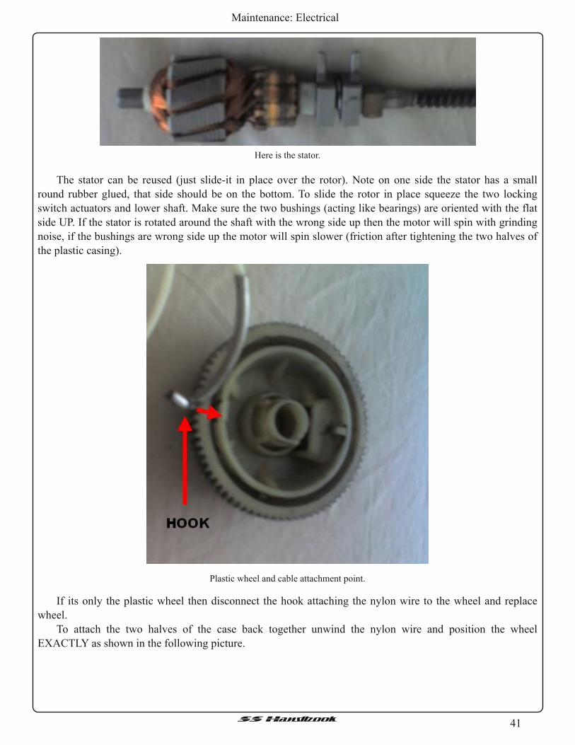
41SSHandbook
Maintenance: Electrical
Here is the stator.
The stator can be reused (just slide-it in place over the rotor). Note on one side the stator has a small
round rubber glued, that side should be on the bottom. To slide the rotor in place squeeze the two locking
switch actuators and lower shaft. Make sure the two bushings (acting like bearings) are oriented with the flat
side UP. If the stator is rotated around the shaft with the wrong side up then the motor will spin with grinding
noise, if the bushings are wrong side up the motor will spin slower (friction after tightening the two halves of
the plastic casing).
Plastic wheel and cable attachment point.
If its only the plastic wheel then disconnect the hook attaching the nylon wire to the wheel and replace
wheel.
To attach the two halves of the case back together unwind the nylon wire and position the wheel
EXACTLY as shown in the following picture.

42SSHandbook
Maintenance: Electrical
Notice the notch called stopper, that notch can not be in the RED area. Can be positioned in ANY position
around that green circle but better orient the wheel in the exact position as shown with minimum nylon wire
on the wheel (notice the hook that is the end of the nylon wire, less than ¼ of a turn).
Observe the small wheel on the cover. Make sure the wheel is oriented in EXACTLY the position
indicated (the missing tooth should be towards the red line shown in the picture below). That wheel is what
stops the antenna when fully extended. If the wheel is randomly oriented the antenna will not extend all the
way.
Lubricate with grease all teeth and the drive screw and the area around the little gear. Do not lubricate the
cable or the mast.
Slide the brushes/switched assembly over the shaft (highlighted magenta). If brushes are loose re-gap as
required, then put the cover back along with the clips and screws (replacing the rivets). At the same time make
sure the round gasket over the nylon wire is placed in the correct location.
ALWAYS do a bench test of the antenna; apply 12 V as described above. Allow the mast to travel from
fully retracted to fully extend (several times). Very important, you should hear a distinctive click at the end of
the travel (in any direction). If no click, the shaft does not slides (up or down) disconnecting the power to the
motor. You can observe the shaft sliding up or down with the cover removed. If no distinctive loud click start
all over (something is not assembled correctly).
Hope this will save you $50 or so.

43SSHandbook
Maintenance: Electrical
Reprogramming Key Fobs
Procedure:
1 . Reposition rear compartment trim to access the programming connector located at the left of the rear
compartment (trunk), for sedans. It should be a two pin connector hanging there going to nothing.
2. WAGON: Remove right back body pillar finish panel to access programming connector. THIS IS THE
WAGONS PIN LOCATION SKIP THIS IF YOU DONT HAVE AWAGON.
3. Ground the programming connector by connecting the terminals together.
› The system will verify this has occurred by performing a lock all, unlock drivers door/unlock all, and
trunk/endgate cycle

44SSHandbook
Maintenance: Electrical
4. Press any key on either transmitter.
› This step programs that particular transmitter to the
receiver. The system will verify by performing the
same lock/unlock, lock/unlock cycle.
5. The automatic door locking/unlocking function is
automatically enabled for this transmitter. To leave
it enabled, skip to step 6. To disable the automatic
door locking/unlocking function for this
transmitter, perform the following sequence 3
times.
A. Press the door lock button within 1 ` second of
step C the 2nd and 3rd time through this sequence.
B. Press the door unlock button within 1 second of
step A. Sedan Reprogramming Connector
Wagon Reprogramming Connector
C. Press the trunk button within 1 second of step B.
› The receiver will cycle through the lock, unlock, trunk sequence 3 times as verification.
6. To program a second transmitter to the receiver, repeat step 4 with the second transmitter. Otherwise, skip
to step 7.
7. Disconnect the programming connector.
› System will not operate if ground connection is not
removed.
8. Verify operation of each transmitter.
9. Reposition rear compartment trim, for sedan.
10. WAGON... .Install right back body pillar finish
panel, for wagons.

45SSHandbook
Maintenance: Exhaust
AIR Pump Disable
Exhaust
GM TSB for Air Pump Disable - http://www.impalassforum.com/tech/engine/air_pump/air_pump.htm
Technical - Water in AIR Pump and/or DTC P0410, P0412, P0415, P0416, P0100, P0101 , P0102 or DTC
48 (AIR System Disable Procedure) #01 -06-04-011
Water in AIR Pump and/or DTC P0410, P0412, P0415, P0416, P0100, P0101 , P0102 or DTC 48 (AIR
System Disable Procedure)
•19951996 Buick Roadmaster•19951996 Cadillac Fleetwood•19951996 Chevrolet Caprice, Impala SS with 4.3L or 5.7L Engine (VINs W, P RPOs L99, LT1)
Condition:
• Some customers may comment of a hesitation during heavy/full throttle acceleration.• A 1996 vehicle may also set any of the following DTCs:
o P0410o P0412o P1415o P1416o P0100o P0101o P0102
• A 1995 vehicle may set a DTC 48.• There will also be evidence of water in the AIR pump.
Cause:
Under high engine speed and load conditions, hot exhaust gasses may leak past the air check valves. As
the exhaust gasses in the air tube cool, water vapors collect into the AIR pump. As the vehicle is driven,
condensation from the AIR pump may come into contact with the Mass Airflow Sensor through the AIR inlet
hose. This condition may cause a hesitation on acceleration and may also set the DTCs.
Correction:
To correct this condition, a Secondary AIR Injection Pump disable procedure has been developed. (It has
been determined that the Secondary AIR Injection system is not required to meet emission requirements for
these vehicles only.)

46SSHandbook
Maintenance: Exhaust
1 . Locate the relay center (1 ) and air
cleaner box (2).
2. Remove the AIR hose and clamp (1 )
from the air cleaner box.
3 . Insert the plug (2) into the air cleaner
box AIR hose inlet (3).
4. Install the AIR hose and clamp (1 ) to
the air cleaner box.

47SSHandbook
Maintenance: Exhaust
5. Remove the cover (1 ) from the relay
center (3).
6. Remove AIR pump relay (2) from the
relay center (3).
7. Install the relay cover (1 ).
8. Install new emission label to radiator
support (3).
9. Update vehicle calibration. (1 995 4.3 L
L99 Caprice, and 1996 vehicles)
Part Number Description Qty.
1 2569122 AIR Inlet Hose Plug 1
12569123 New Emission Label 1
Parts Information

48SSHandbook
Maintenance: Exhaust
Labor Operation Description Labor Time
J6930 AIR Disable Procedure 0.2 hr.
This is a unique labor operation number for use only with this bulletin. This number will
not be published in the Labor Time Guide.
Parts are currently available from GMSPO.
Calibration Information
The Calibrations are electronic calibrations and are NOT available from GMSPO. Calibrations will be
available from Techline starting February 2001 , on the TIS 2000 version TIS 2.0/2001 data update or later.
Warranty Information For vehicles repaired under warranty, use:
1 995 4.3 L (RPO L99) Caprice and 1996 vehicles should also use this add time for reprogramming:
Labor Operation Description Labor Time
J6355 Powertrain Controller --
Reprogram -- On Car
Use Published Labor Times
© Copyright General Motors Corporation. All Rights Reserved.
Notes:
› For a 1994 – early 1995 with stock exhaust manifolds, and you delete the AIR pump system, you will
need a ⅞-18 drain plug. Dorman P/N #65231 , UPC #74956523159
› For a late 1995 – 1996 with stock exhaust manifolds, and you delete the AIR pump system, you will need
a ¾-16 drain plug. Dorman P/N #65226, UPC #37495652261 .
EGR Valve Replacement
A bad EGR is one of the common repairs to the B-body LT1 . It will cause hesitation, stumble, and hurt
gas mileage. It’s an easy fix but a little pricey and annoying.
Get a new one or get the 6-speed EGR valve from the F-Body LT1 . The F-body style tends to last longer
and is the same price anyway. Also go ahead and get the solenoid as well, they’re not that much and it’s good
to replace it while you’re back there.
Tools:
• 13mm wrench• 13mm socket and ratchet
Materials:
• 17113382 OEM EGR Valve (Good)• 17113381 FBody EGR valve (Better)• 12337972 EGR Valve Gasket• 1997223 EGR Solenoid
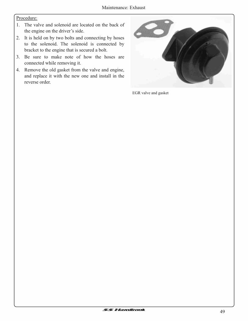
49SSHandbook
Maintenance: Exhaust
Procedure:
1 . The valve and solenoid are located on the back of
the engine on the driver’s side.
2. It is held on by two bolts and connecting by hoses
to the solenoid. The solenoid is connected by
bracket to the engine that is secured a bolt.
3 . Be sure to make note of how the hoses are
connected while removing it.
4. Remove the old gasket from the valve and engine,
and replace it with the new one and install in the
reverse order.
EGR valve and gasket

50SSHandbook
Maintenance: Fuel System
Fuel System
Fuel Filter Change
Fuel Pump Removal
The fuel filter needs to be changed every 15-20,000 miles under extreme driving conditions.
› Be sure to use either a LED work light or an explosion proof light. You don't want fuel to get on the bulb
and possibly cause it to shatter. You'd be riding in your B-Body in paradise before you realize it.
Procedure:
1 . First, you need to raise the vehicle where the driver’s rear wheel is off the ground, the filter is located
under the body in front of that wheel.
2. To relieve the pressure from the system remove the gas cap. It’s best to unplug the fuel pump by the
wiring harness directly under the body below the tank fill tube while the car is running and let it stop. It
will take a second or two.
3. With the gas cap off, remove the bolts to the harness holding the filter in place.
4. Then use a set of pliers and a flathead screwdriver to unhook the hoses from each end. This is a little
tricky, but give a good look to them and you’ll see how they come off. Remember: There is still gas in the
lines and it will pour out, so have a pan handy and then keep it there until the gas runs out. It helps to tilt it
and remove the leftover gas in the filter.
5. Reinstall the new one in the reverse order making sure it is in the right direction and the hoses are secure
to the filter.
6. Reconnect the harness if you chose to disconnect it and crank the car. Turn the key to the “Run” position
and let the pump prime the lines before cranking.
Safety:
1 . Safety First - Chock the front wheels or put
something in front to keep the car from rolling
forward.
2. Raise the rear of the vehicle a good amount. The
rear wheels of the Wagon should be at least 3" off
the ground. This should be just enough to use a
transmission jack and keep the tank mounted on it
and slide it out.
Procedure:
1 . Loosen both hose clamps on the filler neck and the
one on the vent tube. When the tank mount end
comes loose, tighten back up the other end.
Tools:
• Flat Head Screw Driver• Ratchet and Sockets, 13mm• A Couple long Extensions• Fuel Line Disconnect Tool
Filler neck and vent tube.

51SSHandbook
Maintenance: Fuel System
Tanks strap mounts.
2. These are the tank strap mount bolts; they are
1 3mm and a pain to get back in place. Loosen and
remove the nut, but leave the bolts in place for now.
Take the cross strap nut off and push the tank strap
out of the way.
Zip-Loc bags over filler neck.
3. Now position a floor jack or transmission jack
underneath the tank to support it. Put some pressure
on the tank to take the load off the bolts for the
straps. The bolts should come out with little effort.
Transmission jack.
4. Lower the tank a little bit and slide the jack towards
the rear as you lower to keep the tank balanced.
Remove the hose connection at the filler neck and
cover up the port to prevent a fuel leak using two
zip-loc bags and safety wire or zip-ties. Be careful
and it shouldn’t leak much.
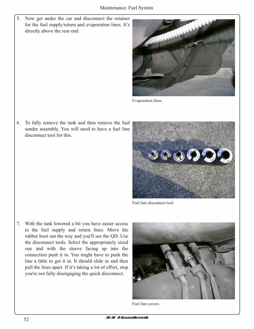
52SSHandbook
Maintenance: Fuel System
5. Now get under the car and disconnect the retainer
for the fuel supply/return and evaporation lines. It’s
directly above the rear end.
Evaporation lines.
Fuel line disconnect tool.
6. To fully remove the tank and then remove the fuel
sender assembly. You will need to have a fuel line
disconnect tool for this.
7. With the tank lowered a bit you have easier access
to the fuel supply and return lines. Move the
rubber boot out the way and you'll see the QD. Use
the disconnect tools. Select the appropriately sized
one and with the sleeve facing up into the
connection push it in. You might have to push the
line a little to get it in. It should slide in and then
pull the lines apart. If it’s taking a lot of effort, stop
you're not fully disengaging the quick disconnect.
Fuel line covers.
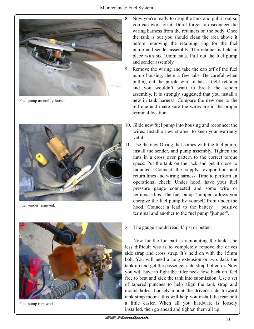
53SSHandbook
Maintenance: Fuel System
8. Now you're ready to drop the tank and pull it out so
you can work on it. Don’t forget to disconnect the
wiring harness from the retainers on the body. Once
the tank is out you should clean the area above it
before removing the retaining ring for the fuel
pump and sender assembly. The retainer is held in
place with six 10mm nuts. Pull out the fuel pump
and sender assembly.
9. Remove the wiring and take the cap off of the fuel
pump housing, there a few tabs. Be careful when
pulling out the purple wire, it has a tight retainer
and you wouldn’t want to break the sender
assembly. It is strongly suggested that you install a
new in tank harness. Compare the new one to the
old one and make sure the wires are in the proper
terminal location.
Fuel pump assembly loose.
Fuel sender removed.
Fuel pump removed.
10. Slide new fuel pump into housing and reconnect the
wires. Install a new strainer to keep your warranty
valid.
11 . Use the new O-ring that comes with the fuel pump,
install the sender, and pump assembly. Tighten the
nuts in a cross over pattern to the correct torque
specs. Put the tank on the jack and get it close to
mounted. Connect the supply, evaporation and
return lines and wiring harness. Time to perform an
operational check. Under hood, have your fuel
pressure gauge connected and some wire or
terminal clips. The fuel pump "jumper" allows you
energize the fuel pump by yourself from under the
hood. Connect a lead to the battery + positive
terminal and another to the fuel pump "jumper".
› The gauge should read 45 psi or better.
Now for the fun part is remounting the tank. The
less difficult was is to completely remove the drives
side strap and cross strap. It’s held on with the 15mm
bolt. You will need a long extension or two. Jack the
tank up and get the passenger side strap bolted in. Now
you will have to fight the filler neck hose back on, feel
free to beat and kick the tank into submission. Use a set
of tapered punches to help align the tank strap and
mount holes. Loosely mount the driver's side forward
tank strap mount, this will help you install the rear bolt
a little easier. When all you hardware is loosely
installed, then go ahead and tighten them all up.

54SSHandbook
Maintenance: Fuel System
Repairing the Fuel SSender
Tools:
• Fuel Line Disconnect Tool• Flat Head Screw Driver• Ratchet and Sockets• A Couple of Long ExtensionsMaterials:
• Ziploc bag• New Wiring Harness, like AIRTEX #WH3000• Ketchup – The mild acid helps clean off the corrosion.
Follow the procedures under “Fuel Pump Removal” but stop before removing the fuel pump from the
tank. Before you remove the fuel sender assembly and before you do anything else, remove all the rust off the
outside portion of your sending unit and paint it. You could bake it in the oven for 4 hours at low heat (170°)
which really does a nice job curing the paint. Do not go any hotter than that or you could burn the paint.
Where they sit in the vehicle, these sending units get no
breeze and so they are very susceptible to corrosion
because dirt, salt, and moisture just sit up there.
Okay, now that it's rust-proofed, let's refurbish it.
Using an ohmmeter, ohm out your sending unit
(purple and black wires) to see what it reads full (float
up) and empty (float down). Factory spec is 90 full and
0 empty. Low fuel light comes on at 10 Ohms. This one
was not doing so well:
This is caused by a combination of things:
• Lousy connections filled with gasoline varnish.• Corrosion and burn damage on the ends.• The stock GM resistor setup isn't always calibrated
right. You'll see as we go.You use whatever method you want to clean these
metal areas shown in the pictures.
An example of a bad full reading.
An example of a bad empty reading.

55SSHandbook
Maintenance: Fuel System
These got a little hot!
Look how heat-damaged the fuel pump wires were.
See the insulation melted back?
Torx in action.
Spring
Procedure
1 . Take the sending unit apart using a Torx bit. Under
the cap is a spring, which may jump out if you
aren’t careful.
2. Current is conducted through the spring to the
resistor. As the fuel sender ages, it builds up
corrosion and that changes the resistance of the unit
changing the reading on the gauge. Remember, don't
lose the spring.

56SSHandbook
Maintenance: Fuel System
A dirty wiper.
3. Start cleaning every contact but be delicate on the wiper. Using an eraser is a good idea. Just be firm
enough to clean off the corrosion yet not bend or break the wiper. A clean wiper conducts current better
and produces more accurate readings at the gauge.
A clean wiper.
4. Once you are finished with the wiper begin cleaning
the rotator connection any way that you can. Here
it’s being pointed to with a jeweler's screwdriver.
The rotor.
Fine grit sand paper.
5. Fine sandpaper works well. It is suggested to use
2000 grit or higher to clean the rotor. Of course
contact cleaner wouldn’t hurt either. After cleaning
the rotor with sandpaper, be sure to blow it off
several times. You don’t want to have any of the grit
entering you engine and causing more problems.

57SSHandbook
Maintenance: Fuel System
Spring mount.
6. Clean where the spring mounts to the assembly. The
spring is sandwiched between the assembly and the
resistor cap.
Cleaning the resistor.
These got a little hot!
7. Clean the corresponding resistor area with a pencil
eraser.
Be VERY gentle with the resistor. The wire isn't real
strong so take your time. If you break it, it's dead and
all of your work to this point will be for nothing.
Also don’t forget to clean the edge where the wiper
rides.
8. Carefully clean the spade connector at harness
connection.

58SSHandbook
Maintenance: Fuel System
These got a little hot!
9. Once everything is clean, put it back together and
check “EMPTY” with your ohmmeter. If yours is
still reading more than zero ohms, it needs help. It
may do this because the wiper never gets close
enough to the spring to have no resistance in the
circuit path. If that is case, you need to
RECALIBRATE the resistor. If you're good with a
soldering iron, this is no problem. Here's how to do
it. Find the highest point on the resistor where the
wiper travels, shown here with a pencil. Then, run a
bead of solder all the way from that point up to the
spring mount, so there is a direct, low-resistance path
from the wiper to the spring when the gas tank is
empty. NOTE that the jaw is NOT grabbing the
resistor itself, but the plastic housing. Be gentle with
that resistor wire!
Not so good solder application.
10. Now, you need to run a bead of solder from the
spring mount to that point. Use some good paste flux
to make sure the wire is super clean so you get a
good bond. Start at the mark and then work your
way towards the spring mount. Be careful not to let
the solder flow farther away, although all that will
do is give you a slightly false low, which isn't really
a bad thing. Cleaning carefully will ensure that the
solder doesn't bond to anywhere you don't want it to.
Solder HATES dirty metal and refuses to bond to it.
With soldering just starting here and the solder
quality doesn't look too good - see how it's beading
up?
A good solder application.
11 . Finished! See how the solder has flowed nicely onto
the resistor wires, this is what you want to see.

59SSHandbook
Maintenance: Fuel System
Here's the finished product.
12. Now, begin bolting everything back together.
No bodies just solder.
1 3. The next step is to install the new harness. Here are
some more tricks.
› DO NOT install the plastic connector bodies. Just
solder them directly to the top of the bulkhead like
this picture. No more vibration or contamination on
these connections! They'll never need to come off so
don’t worry. However, for the fuel pump, cut the
connectors off the ends of the leads, strip 1 /4" of
insulation off the wires, and solder them directly to
the fuel pump leads side-by-side so if you ever need
to replace the fuel pump, you just touch the hot
soldering gun to the joint and the wires come right
apart.
Testing the sender.
› DO NOT heat-shrink any of these connections
unless you have heat shrink tubing you KNOW is
gasoline resistant. Most of them aren't, and if you're
in doubt, just take a piece of what you have and put
it in a little jar of gasoline and give it half an hour. If
the surface feels gooey after the half-hour, it's not
resistant. Honestly, you don't need to protect the
connections. They don't move around any, so they
won't touch.

60SSHandbook
Maintenance: Fuel System
Checking the harness.
14. Okay the moment of truth. Check at the sender itself.
Empty should read 0 Ohms, this one looks good!
Next you need to check the harness, which should
read what the sender itselfmeasured.
Checking "Full".
1 5. Lastly check the sender for its “Full” reading. Here
you can see the meter reading 96.1 ohms. This is
okay. Anything 90 ohms and above will show as a
full tank. The real key is getting the “Empty”
resistance as close to zero as possible.
Okay, you're all done. Take the sender and go plug it
into the vehicle harness, then turn the ignition on.
You can verify the gas gauge circuit is working by
watching the gauge on the dash respond to you
moving the float. Then bolt everything back together
and put the fuel tank back in.
New Sending Unit
New Sending Unit part number ACD#FLS1072 GM#19179521 which is the part number to supersedes
the original #25028955
It looks like GM redesigned the sending unit, correcting everything that gave us issues with the old one.
The only contact that isn't well secured from varnish and corrosion is the one between the arm and resister
and it appears to be self-cleaning. Below are a few pictures of the newer style fuel sender.
Newer style fuel sender. A close up of the other side.

61SSHandbook
Maintenance: Fuel System
A nice side shot. A view of the wiper.

62SSHandbook
Maintenance: General Maintenance
General Maintenance
Air Filter Replacement
Broken Window Roller Fix
Problem - The rear of your power window falls down out of the track or sags when the window rolls up. Any
door can be guilty of this.
Solution - Replace both original "Rectangular" shaped window rollers with the newer style Round nylon
rollers. It's nearly always the rear window slider that breaks, But If you really want to do this fix right,
replace both Front and Rear sliders in the window track while the door panel is off! ! ! Rarely does the 3rd
regulator arm slider break in the lower track.
Tools:
• 5/16" Drill bit• 2" CClamp• Door pad plug tool• Small flat screwdriver• Short Stubby flat screwdriver• Phillips screwdriver• Channel lock pliers• Hand rivet gun• 3/8" open end wrench (Only for Nut/Bolt hardware
method)• Bearing grease• White spray lithium grease (Can)• Blue painters tape• Magnet tool (Just in case).Materials:
• Nylon Rollers (2) – GM #9666748 (Per door)• Retainer Clips (4 or 5) – GM #10161510 (Per door)
ORMaterials Optional:
• Nylon Rollers (2) – Dorman part # 74444• Aluminum rivets (6) 3/16" OR • 1024 x 1/2" Bolts (6)
• 1024 "Nylon Insert" locking nuts (6)
Sample tools.
In this example, both sliders on the driver side door on a ‘95 Caprice. The process is similar on the other
doors as well. Remember, these door panels, armrests and switch panels are fragile! So take your time and go
easy on them when removing them!
The air filter is located on the driver side of the engine compartment. Remove the two screws holding the
air box lid in place and pull up, push down on the backside, and out to lift the lid. Pull out the filter and
reinstall a new one.

63SSHandbook
Maintenance: General Maintenance
Armrest screws
Latch screw.
Door pocket clips on the ends.
Procedure:
1 . Remove the 2 screws that hold the armrest to the
door, then gently lift the back of the armrest up a
small amount and pull out and remove it.
2. Remove the screw in the center of the door handle
pocket (Behind the door handle).
3 . Then carefully insert a small flat screwdriver in
either end of the pocket and press in on the clip that
holds the pocket in, then pull out on the pocket until
the clip clears the door panel. Repeat on the other
end of the pocket, lift the pocket out and over the
door handle. Watch out for the clips on the ends of
the door bezels.

64SSHandbook
Maintenance: General Maintenance
Lower door panel screw.
4. Remove the Phillips screw in the door panel at the
bottom of the back end of the door panel.
Typical door panel clip locations.These got a little hot!
Electrical connector for the window switch.
5. Using a good door panel plug tool, locate the door
panel plugs. The gently pull out in an area close to
rear of the door panel, and pop out the 1 st door panel
plug with the tool. Repeat until all four door panel
plugs are removed from the door.
Now carefully grab the door panel near the top on
both ends and lift up on the Rear of the door panel
1 st until the inside seal comes out of the track, then
lift up on the front end and gently work the door
panel up and out of the doorframe.
Remember, the window switch still needs to be
disconnected before the door panel can be removed
completely! Remove the electrical connector by
pressing down on the light green tab, then pulling
out on the connector (not the wire harness) to the
window switch, while holding the switch in place in
the door panel. Now remove the door panel.

65SSHandbook
Maintenance: General Maintenance
Arm rest support.
6. Now gently remove the plastic door paper from the
inner door and set it aside. Remove the window
switch from the door panel itself, then temp hook
the switch back up to the wire harness connector.
Key in the “On” position, slowly lower the window
until you can see the broken slider at the rear of the
window track thru the hole behind the armrest
bracket.
› Note: Step 5 also involves removing the armrest bracket for greater access to the rear window roller area
as explained below. This step is optional! Some people do it, some don’t. If you don’t intend to remove
the armrest bracket. . . .Skip to step 7Stuff and old towel into the bottom of the inside of the door (To catch rivets and debris) and using a 5/16"
drill bit. . . . .Drill out just the center head of all 4 armrest bracket rivets, don’t go any deeper - all you want to do
here is just remove the rivet head. Gently tap out the rivets, then remove the bracket and set aside.
7. Notice that the end of the track is crimped in slightly.
These crimped in areas must be opened enough in
order to get the old sliders out of the track, and the
new round rollers in the track. Using a large flat
stubby screwdriver, stick it in the rear of the track
and pry open the crimped areas until the broken
slider can be slid out and removed.
If you are replacing both front and rear sliders in the
fix, then it is easier to drill out both rivets in the ends
of window slider track using a 5/16" drill bit, and
removing the track from the window and door itself.
Do this after you have uncrimped the rear of the
track. You will have to slowly raise/lower the
window in order to gain access to the rivets. My
vehicle had been fixed in the past on this window so they used nuts and bolts in the track instead of rivets
for the fix.
Crimped end and broken roller.

66SSHandbook
Maintenance: General Maintenance
Window supported by tape.
8. Once the two rivets have been drilled out of the
track, get a roll of the "Blue Painters Tape" and by
hand, lift the window up from the inside and outside
of the door until it reaches the top, then tape the top
of the window to the door frame to hold it up. Better
to use the blue tape which comes off easier with no
leftover adhesive like duct tape.
Popping out the ball stud.
Pressing in the ball stud into the new roller.
9. Now you'll see that the track is free of the window,
and ready to be removed from the door, but 1 st you
need to pop the remaining good slider out off the ball
stud at the front. Use your door panel plug tool and
carefully apply pressure to the slider until it pops out
the ball stud. After closer inspection, the front slider
had also already cracked in one spot, and needed to
be replaced. Now guide the slider track out if the
rear hole of the door.
1 0. Now get some bearing grease and apply a small
amount to the center holes of the new round rollers,
then using a 2" C-Clamp, carefully align the C-
Clamp, roller and ball stud of the rear regulator arm
up, and slowly tighten the C-Clamp down until the
roller pops onto the ball stud.
› If you are using the Dorman #74444 rollers you will
need to drill them out using a 11 /64" bit so they have
the same inner diameter as the GM roller.

67SSHandbook
Maintenance: General Maintenance
Front ball stud is harder to get to.
Don't forget to lubricate the joints. Lubricate the gears as well.
11 . Repeat the process on the Front ball stud. This one is
a bit harder, but can be accessed by "Carefully"
lifting the regulator arm with the window switch
toward the top of the door until you align the access
hole in the picture below. The clamp will need to be
slid into the inside of the door, but it will fit and
work. Patience on this one!
1 2. Remove the old sliders from the slider track and wipe the track clean of any debris and old grease. Get
your grease again and apply a thin new layer to the inside of the slider track where the rollers go. This is
also a good time to lubricate the regulator sprocket and scissors arms area where they cross, and also
grease the lower scissors arm track where the 3rd window door slider rides in. Also a good time to spray
some white grease lubricant into the lock arm connections, face lock and lock mechanism parts that are on
this inside of the rear door while the door panel is off! Any lock rods that were knocked off or adjustments
needed to be made - Fix them now too!

68SSHandbook
Maintenance: General Maintenance
Aligning the holes.
Pop rivets.
Screws and lock nuts.
1 3. Now insert your slider track back into the rear hole
in the door, insert the rear round slider into the track,
then guide the track thru the door and onto the front
slider. If needed, the track can be rotated to get both
sliders onto it, but if you opened both crimped ends
of the track, you won’t have to do this.
1 4. Once the track is back onto both sliders, carefully
remove the Blue tape that holds the window up
while holding the window in place so it won’t fall!
Now slowly lower the window until you can align
the slider track back up with the holes in the window
track. You'll likely have to slide the track left or right
to line up the holes.
1 5. Now this part of the fix is your option. You can use
3/16" aluminum rivets to re-attach the slider track to
the window frame, or you can use 10-24 x 1 /2" Bolts
and 10-24 "Nylon Insert" locking nuts for the job.
This example used the rivets because they’re a more
permanent fix but, the locking nuts should work too.
Do not use regular nuts they will come loose.
Locking nuts are a must here if you aren’t using
rivets!

69SSHandbook
Maintenance: General Maintenance
Rear rivet.
Front rivet.
16. The rivets are kind of tough to get installed in the
track, but you can get a hand riveter in both places
in the door but you have to "slowly" adjust the
window Up/Down to get the position just right to
do it. Do the rear hole first if you are using rivets on
this fix.
1 7. Once the Slider track is re-attached to the window
frame at both ends, it's time to check your work and
see if the new sliders are working and the window
rolls up properly? If all is good, it's time to re-install
the armrest bracket to the door. Again, you can use
the 3/16" aluminum rivets or the 10-24 x 1 /2" Bolts
and 10-24 "Nylon Insert" locking nuts for the job.
It's your call.
› Be sure that the window is in the rubber window
track as well. You'll know its not if it doesn't roll up
or down completely.
1 8. After the bracket is back on, carefully remove the
towel you stuck into the bottom of the door to catch
any debris you may have dropped. Have a magnet
or shop-vac handy in case you need it and DON’T
leave any metal in the door that can rattle around
while you’re driving.
1 9. Now remove the window switch from the harness connector again. Time to re-apply the plastic door paper
to the door. Some people think that you should use a hot glue gun and the clear glue, start at the top of the
door and apply the whole top area 1 st. It should be easy to tell where the plastic was before so just re-
apply it. Once the top is in place, apply the rear area, then the front area. Now slide the electrical harness
for the window switch thru the hole in the plastic, then glue the lower section down to the door
› Note: Some people use tape rather than glue to reapply the plastic. Again, it's your call but the glue works
best and a more professional job.
20. The rest of the fix is basically reverse order: Install the window switch back into the door pad, Make sure
ALL the door panel plugs are good and installed. A good idea is to use all NEW plugs because they keep
the door panel tight on the door. Also, make sure the deadener carpet is still fixed to the door panel? If
not, use the glue gun to stick it back on.

70SSHandbook
Maintenance: General Maintenance
21 . Get the door panel close to the door and then hook the electrical connector to the window switch back
onto the switch. Carefully lift and tilt the top of the door pad window seal into the top door track, then
install the pad back into the track, paying close attention that the door panel is fitted down in both ends of
the door.
22. Now align the door panel plugs (1 at a time) and pop them back into their holes, then re-install the Phillips
screw at the rear of the door panel.
23. Slide the door handle pocket back over the door handle, then pop the pocket back into the door panel and
re-install the Phillips screw.
24. Re-Install the arm-rest and both Phillips screws that hold it on. You’re done!
› Note: All doors are nearly the same process as in this example, but once you've done one door with no
problems, the others will be easier.
Differential Oil Change
When changing the differential oil most people recommend against Synthetic lube with a limited slip
differential (LSD) rear end. They say it’s too slippery to allow posi to work right. Even the most diehard
synthetic user use regular gear oil because of this. Check the option tag in the trunk, if it says G80 you have a
LSD rear end and need to use quality gear oil but not synthetic and use the limited slip additive. If you don't
have a LSD rear end, just use the lube of your choice synthetic is ok.
You can do this one of two ways:
1 . Remove the cover w/ gasket replacement.
2. Siphon the fluid out by the filler hole.
Removing the Cover Technique:
Materials:
• Differential oil 85W90 Synthetic for NO Limited Slip Differential & conventional for positive traction• New Felpro Gasket• GM Slip Additive – Available from dealer for about $10Procedure:
1 . Lift the car up on jack stands and chock the front wheels
2. Have a pan underneath the cover to catch the fluid, loosen the bolts by alternating the sides to prevent
warping of the cover.
3 . When all of the bolts are loose, but not out, pry an edge up and allow the fluid to drain.
4. Then remove the bolts and remove the cover.
5. Check to see what kind of gunk is at the bottom of the casing and inspect for any damaged parts.
6. Remove all of the old gasket from the cover and housing.
7. Reinstall the gasket and carefully replace the cover. Gradually tighten bolts to torque factory specs.
8. Remove the filler hole cap and add the “GM Slip Additive” then fill the differential with the
recommended oil.
9. Replace the fill hole cap and you’re done.

71SSHandbook
Maintenance: General Maintenance
Using the Fill hole Technique:
Materials:
• Differential oil 85W90 Synthetic for NO Limited Slip Differential & conventional for positive traction• Hand pump or siphoning tool• GM Slip Additive – Available from dealer for about $10Procedure:
1 . Lift the car up on jack stands and chock the front wheels
2. Remove the fill hole cover and insert the siphon tube and remove all the old fluid.
3 . Fill the differential with the “GM Slip Additive” then fill the differential with the recommended oil.
4. Replace the fill hole cover and you’re done.
Door Panel Removal
Tools:
• Panel removal tool or large flathead screwdriver• Phillips head screwdrivers, large and small• Small flathead screwdriverOptional, but suggested:
• Extra clips• Stainless screws and finishing washers• PatienceProcedure:
1 . Remove the window switch by prying the front end up and pulling it out, then disconnect the switch wire
harnesses.
2. Pull the door handle, as if to open the door, and remove the small screw behind it, pry the plastic piece
out, be VERY careful they tend to break by removing it this way. Its tricky getting it out due to the
locking mechanism so be patient and careful! When it’s out, disconnect the harness to the lock.
3 . Next, remove the two large screws behind the caps on the gray pull strap.
4. Remove the two small screws in the armrest
5. Then remove the last two. One is at the bottom of the door panel under the storage pocket and the other is
at the top of the storage pocket.
6. Now, pop out the clips. The removal tool is recommended BUT you can use a large flathead or drywall
spatula but be careful, they tend to scratch the paint.
7. Work the clips out all around the panel, there are some in the middle of the panel too. If you break some
clips don’t worry, you can get them at a parts store.
8. To lift it off the door, pull gently upwards & out. You may need to pull the trim piece off the upper part of
the door to get it completely off.
9. The reinstallation is the reverse but here are a few tips:
› Replace any clips that are broken or the feathers have come off. Go ahead and get a bunch, you will
probably need them in the future!
› Take special care with the plastic, as I said before, they break very easy and they don’t come cheap and
junkyards have already been scavenged for them.

72SSHandbook
Maintenance: General Maintenance
Oil Change
Tools:
• Jack and Jack Stands• Oil Filter Wrench• Oil pan or suitable container› You can go to the See Preferred Brands, Oils to determine your oil.
Ah, the old oil change. Well, if you don’t know how to do this, then you’re not a very mechanically inclined
person and you may want to stick to labor charges.
Procedure:
1 . Jack the vehicle up and place jack stands under the frame.
2. Remove the oil fill cap.
3 . Remove the drain plug and let it empty into the oil pan.
4. Next remove the filter with an oil filter wrench and place it on its side or upside down so it can drain as
much oil out as possible.
5. When installing the new oil filter most people use some of the old oil to lube the new filter seal. Go ahead
and pour some fresh oil into the filter, this will help the engine regain oil pressure when cranking and not
have to let it fill it up when you finish. Screw the filter on by hand and tighten a little, there’s no need to
wrench the sucker on, just make sure it’s snug and not moving.
6. Reinstall the drain plug, lower the car and fill it up with new oil. Add four quarts and then check and add
until you get in the crosshairs. Start the vehicle and let the oil flow for a few minutes. Double check the
oil level and you’re done. Please dispose of your oil properly.
7. Now reset your Change Oil light. It depends in the year how this is done.
Resetting the Change Oil Light
› 1994 – Open the fuse panel and find the yellow oil button. Turn the key to the “Run” position, but not
running. Now hold down the yellow oil button for a few seconds. Turn ignition back to off. Now start the
car, light should be out. Replace fuse panel cover.
› 1995-1996 – Turn the key to the “Run” position, but not running. Press the gas pedal three times within
five seconds. You should see the “Change Oil Light” flash a few times and go out.
› For the small screws in the armrest, they tend to break through the gray vinyl. I used some stainless steel
screws with a wide stainless finishing washer. It made a nice touch!
› The lock mechanism, be sure that it is aligned, locks and unlocks when you put it back on!
*The rear doors are essentially the same except you do not have power window switches except for one. It
pries out easily.

73SSHandbook
Maintenance: General Maintenance
Oxygen Sensor Replacement
Oxygen Sensor replacement is recommended around every 100,000 miles. Although it is okay to change
them whenever you want and they may go bad anyway. They will cause bad gas mileage, sluggish
performance and build up due to reading the wrong fuel/air mixture. You cannot “rejuvenate” an O2 sensor or
“clean” it. They will usually go bad during a season change.
For 1995 and before:
You have two O2 sensors, both in front of your catalytic converters. You will need an O2 socket or a
wrench to remove them. It is good to replace them while the exhaust is still a little warm and spray them with
a loosening agent i.e. PB Blaster, WD40. Sometimes they’re easy, sometimes they’re not.
For 1996:
Since a government mandate to help with emissions, the 1996 B-bodies along with all other automobiles
will have O2 sensors after the catalytic converters.
You will have four O2 sensors since you are OBD II. Two are behind your catalytic converters and are
useless except for emissions testing. If you do not have emissions testing in your state you can replace those
with simulators. The other two are in front of your cats and, along with the PCM and a few other sensors
control the entire fuel/air cycle of your car. You cannot replace those with anything other than real O2 sensors
unless you want the car to run like crap. If you convert to OBD I you can leave out the rear O2 sensors
entirely, not even simulators needed. Note: if you live in a state with emissions testing you will still have
problems, as many states are moving to plugging into your PCM for 96 and newer cars and you'll fail if you
have the OBD I conversion.
PCV Valve Replacement
PCV Valve
The PCV valve, or Positive Crankcase Ventilation
valve, is located on the driver’s side of the throttle body
between the #3 and #5 fuel injectors (the ones in the
middle). Many people tend to forget about this small
valve, and it’s recommended to change it every 12
months to 12, 000 miles.
The PCV Valve and Breather Element work together
within the car’s emissions and ventilation systems. They
serve as part of the emissions control system by re-
circulating unburned gases and fumes back through the
intake manifold to be re-burned. Therefore, these gases
and vapors are not expelled through the exhaust system
so air pollution is reduced.
Benefits of changing the PCV Valve:
• Loss of power, oil dilution and even engine failure are avoided• Oil life is extended and engine lubrication is improved• Oil consumption, rough idle and air filter contamination are avoided• Environmental pollution is reduced

74SSHandbook
Maintenance: General Maintenance
Transmission Fluid Change
This is a fluid many people don’t remember to change. Rule of thumb is replacing fluid and filter around
every 30,000 miles as per Shane Cobb “Dustman.” at Carolina Performance Transmission.
Check the fluid while the car is running and at normal operating temperature. Make sure the fluid is
pink/red and does not smell burnt. Even though the fluid is pink or red, does not mean that it is still good and
this is where many people make the mistake of not changing it. It loses its viscosity and detergents over time
and wears your transmission out. It will slowly deteriorate your clutch discs away. You will see the particles in
the fluid, causing your transmission to slip. If this condition goes unnoticed for a prolonged period, changing
it would NOT be a wise decision. Many people have their own theories about this and have a story of a car
that had 300k miles on the same transmission fluid and after they changed it, everything was fine. This very
well may be true, but you will hear more bad stories about this than good. Why else would transmission shops
not change your fluid if they offer a guarantee? Such as AAMCO, they offer a guarantee that if they change
your old transmission fluid, and then it croaks, they will fix it at no charge, BUT if they don’t think it’s a good
idea, as in my situation, they won’t. They looked at mine and said, “I don’t think so, but in about 6,000 miles,
come see me.” Little did I know that I would be back in 6k miles slipping in overdrive. A lot of quick oil
change franchises will not change it depending on the condition because they know about failure and have
seen it happen. So, if you’re in doubt, ask a professional, many places offer 50-60 inspections and if it checks
out then they’ll guarantee it. If not, start saving your money now and think T-56 manual replacement.
Tools:
• Socket wrench• Wide collection pan for fluid• Rags• Flat head screwdriver• New filter and gasket• Maybe some gasket seal• Jack and Jack StandsProcedure:
1 . Pull out the transmission dipstick about 6 inches to relieve pressure. Then raise the vehicle just as you
would for an oil change. Support it and locate the transmission pan, .
2. Begin loosening the bolts around the edge of the transmission pan, but go in a crisscrossed pattern,
loosening a little at a time. The pan is under pressure and you don’t want to warp it in any way. Fluid will
begin to seep out of the edges but don’t worry.
3 . After loosening the bolts a little, place your container under the pan and center it under a corner.
4. Now loosen the bolts more at that corner and use your flathead, gently, to pry the edge down and break
the seal. Be sure not to mar the mating surfaces, which could cause a leak in the near future. You can
loosen the remaining corners to allow it to drain more but it gets messier the more you loosen.
5. After the stream has become a trickle remove all the bolts and drop the pan.
6. Take that pan and clean it, NO CLEANERS, just use a clean lint free rag to wipe it off and clean themagnet thoroughly. The magnet collects loose debris and shavings so don’t pick it off with your bare
finger or you’ll get metal splinters.
7. Clean off the entire old gasket from the pan and the surface of the tranny.
8. Now remove the old filter. Be easy on it, just twist it a little to break it loose and wiggle it as you pull

75SSHandbook
Modifications: Basic Mods
down gently. Now insert the new filter into the same hole.
9. Placing the gasket on can be a pain because it likes to move around and probably is deformed from being
in the box. Some people use little stems that hold it in place by the bolt holes or it will stay in place if you
use a sealant.
1 0. After you get a few bolts started, insert the rest to be sure you have everything lined up and the gasket
isn’t wrinkled or out of place.
11 . Tighten the bolts to specs and don’t over tighten them. The gasket will begin to squeeze out of the sides.1 2. Pour about 4 quarts of fluid in the transmission. Lower the vehicle and crank it up. Move the shift lever
through all of the gears a few times and let the run warm up.
1 3. Check the fluid while the car is running and slowly add fluid until the right level is obtained.

ModificationSS

77SSHandbook
Modifications: Basic Mods
Basic Modifications
Bow Tie Install
Stock bow tie. Red and blue bow ties.
Many people do not like the standard silver bow tie on the SS grill so many have chosen to go with a red
one. You can buy the red bowtie a few websites or even form the dealer. Part numbers can be found in the part
number section.
Procedure:
1 . Lift the hood and look at the backside of the grill.
2. There is a hole behind the original bow tie. Use a rod or screwdriver to press the old bow tie out. It is
stuck in place by two sided tape so push slowly while applying back pressure to the grill for leverage and
this will also keep you power freaks from cracking the grill mounts.
3 . Once you break a section loose, you can go back to the front of the grille and remove the rest with fishing
line, using it like a saw, or a flathead screwdriver to pry it out.
4. After it is out, clean the surface and remove any of the old adhesive tape. Now install your new bowtie,
stand back, and enjoy.

78SSHandbook
Modifications: Basic Mods
Throttle Body Bypass
Here is the way most people suggest doing the Throttle-Body Bypass on a 94+ B-body LT1 &
L99.(Instructions might be a little different on a '94, and the process might work on F-body and Corvette LT1 )
Tools:
• Socket wrench• Flat head screwdriver• pairs of pliers• door panel removal tool (will also help
whenever you remove one of your doorpanels)
• small clean bucket• sharp knife or scissorsMaterials:
• Spare rags• 1 ziptie (optional)• 2 caps (rubber from hardware store or
billet from AutoCandy.com)• A few feet of 7/16" ID rubber hose (fuel
line) from a hardware store (optional)Now would be a good time to put in a
160 deg Thermostat and flush the system.
Many people recommend using regular
Anti-freeze (the green stuff) instead of the
Dex-Cool that General Motors suggests. If you do decide to use Dex-Cool again, DO NOT PUT IN THE
CLAY TABLETS! They will most likely dirty up the coolant and might even clog your heater core.
Preparation:
Turn the engine off and let it cool for a while before beginning. Leave off until finished. This will help to
keep you from being injured, and the coolant will not be flowing. Put the bucket below the water pump (as
indicated in the picture) Put spare rags on the intake manifold (or Home Plate) and stuff one under the small
rubber elbow (blue) that connects the metal pipe (green) to the throttle-body.
Procedure:
1 . Unscrew the screw-type hose clamp from the coolant resevoir. Remove the overflow hose and carefully
lower the end into the bucket (as shown in pink). Coolant will probably begin spilling out of it. This
should not last but a few moments. Reconnect the hose to the coolant tank and tighten the screw clamp.
2. Unscrew the screw-type hose clamp from the throttle-body side of the hose (orange). Disconnect the
overflow hose, and move it to the metal pipe (green). Decide how much of the stock hose you want to
trim off (just a few inches) and cut it. Remember: measure twice, cut once. You do not want the hose to
hit the alternator or serpentine belt, so don't cut too much. Then reconnect the small length of hose that
you cut to the throttle-body. This should keep any more coolant from falling on the water pump and Opti-
spark. Let the long length of overflow hose from the coolant tank hang down out of the way. There should
Simple image of bypass.

79SSHandbook
Modifications: Basic Mods
no longer be coolant in it, so you should not have any problems.
3 . Using the door panel remover, disconnect the rubber elbow (blue) from the throttle-body.
4. Get the two pairs of pliers. Use one to rotate the rubber hose (blue) and the other to rotate the clamp until
you can see the ends of the spring clips holding the tube on the long metal pipe (green) that runs from the
rear of the engine to the front between the valve cover and the intake manifold. Move the spring clip
inward (away from the end of the hose) by squeezing the clip with the pliers. Then slide the hose off the
pipe (green).
5. Take the long length of overflow hose (purple) from Step 2 and attach the unconnected end (the end that
you previously cut) to the metal pipe (green). Use the screw clamp from the front of the throttle-body
(also in Step 2) to hold it together. You might decide to use a zip tie (yellow) to attach it to the larger
heater hose so it doesn't move around too much.
6. Start the car and let it run for a few minutes to make sure everything is connected properly. Double-check
all the connections and clamps.
› If you do not decide to switch anti-freeze, or flush the system, you will need to add some more anti-freeze
to compensate for the amount that you lost. Fill the tank to the appropriate marker on the reservoir. Bleed
the system as it says in the Factory Service Manual or See Bleeding the System.

80SSHandbook
Modifications: Electrical
Electrical
Antenna Switch
This is a good idea if you still have the stock radio and you want to lower the antenna while listening to
CD’s. You can put the switch in almost in location. Some people have mounted them in the coin holder, in the
ashtray, or anywhere else, you can imagine.
Sample switch schematic
Materials:
• One SPST contacts Rocker Switch, toggle or slider,from Radio Shack Digikey, Mouser or many others.
• Some extra wire of similar gaugeUse the removal instructions from www.installdr.com
Procedure:
1 . Begin by removing your ashtray and the lower dash.
2. Pull out the radio by removing the four screws that hold it in and unplug the two harnesses and antenna
wire.
3 . Select where you want your switch to go and drill a hole but don’t mount it yet. Just test fit it.
4. Find the Antenna wire in the #8 position of the biggest harness. Schematics say pink but it could be green.
5. Tap into this wire and solder in a piece of your spare wire to each end that was just cut.
6. Now slide your wires through the ashtray slot and allow them to dangle.
7. Re-install the radio and lower dash, just snap it in place for now. There’s no need to completely re-install
it yet.
8. Position the ashtray and route your wires making note of the route you are going to take. It is very easy to
place the wires where they are in the way of the ashtray closing.
9. Now solder some short wires, about 12 inches, to your switch terminals.
1 0. Install the switch into wherever you are going to put it, like the ashtray for example.
11 . With your route set and switch in place. Mate your loose wires. Just twist them together at first to make
sure it works.
1 2. Turn on the radio and see if it works. If it works, shorten your wires to a decent length, connect them and
re-install everything.
Notes:
› It’s recommended that you use connectors just in case you need to take things apart later.

81SSHandbook
Modifications: Electrical
Pass Key Fault Disable
Materials:
• One or more resistors to match your key• Two pieces of heat sink tubing sized for each wire, about ¾” long• One piece of heat shrink tubing to cover the whole assemblyProcedure:
1 . Use a voltmeter to read the ohmage of the chip in your key. Do this by placing one lead on one side and
the other lead on other side of the chip.
2. After determining your ohm rating, get a resistor(s) that equal the ohm you need. Ex: If your key
measures 1 .1 kilo ohm get a 1 K resistor and a 100 ohm resistor.
3 . If you only need one resistor, go on to step 4. If you need multiple resistors, tie the resistors together as a
chain link. DO NOT lay them side by side and twist together. A little solder will help hold these together.
4. Unplug the harness (above) located under the steering column. Insert one end of the resistor chain into
one hole of the [purple/white & black/white] harness leading to the module. Then plug the other end into
the other hole. The snugness of these wires may not be sufficient so hold them in place with some
electrical tape temporarily.
5. Insert you key and attempt to start your engine.
If it works:
The car will crank and the Pass Key Fault LED will go out. It is suggested that you fully solder the
connection then cover the connections with heat shrink tubing and shrink in place. Next, apply heat shrink
tubing to the assembly and shrink the tubing in place. Be sure not allow them to touch each other with the
exception of the solder spot. Next, you should zip-tie the wires out of the way so that they aren’t snagged by
anything else. After you do this be sure it still works and that you haven’t altered anything in the process of
cleaning up.
If it doesn’t work:
The car will not crank and the Pass Key Fault LED will blink repeatedly or will stay on. If it blinks
repeatedly, you are not getting a connection. Get a second hand to turn the key while you hold your resistors
in place. Keep trying until it works or the LED at least stays on even though the car may not crank.
If getting an extra hand to help works, see above and finish cleaning up. If not, be sure your voltmeter
is working properly (if you have one with a needle, make sure it is set at 0 with your adjustment knob) and
then double-check the your ohmage from the chip in your key. Repeat procedure.

82SSHandbook
Modifications: Electrical
Notes:
› By chance, the car cranks but
the LED stays on. It is because
your ohms are slightly off. In
other words, it is sensing that
your key chip is losing its luster
and that you need a new one but
it’s going to crank anyways.
You don’t need a new key, but
you do need to recheck your
ohms and repeat the process.
› Although the module has been
disabled, you cannot crank the
car with a key that does not
have the chip in it.
› Here is a chart to help you
decipher the color code on
resistors.

83SSHandbook
Modifications: Electrical
Radio Wiring Chart
Tachometer
Advantages
Installing the tachometer allows you to monitor engine RPM, a feature that is sorely missed by some 94-
95 owners. Other gauges can be installed in '96 models to monitor oil pressure or voltage levels.
Disadvantages
You have to install a non-factory gauge in the interior of the car. It requires some cutting of (replaceable)
interior pieces.
Materials:
• Replacement black dashboard instrument cluster bezel (P/N ???). Optional, but good insurance. About$15.
• A 2 1/16" tachometer. No matter what you get, make sure it is at most 2 1/16" wide and no deeper than 31/2".
• 18 gauge wire and a length of black ribbed wiring conduit. About $5.• Soldering iron or some other method of splicing.
10 9 8 7 6 5 4 3 2 1
20 19 18 17 - - - - - -
Harness side pin out.
Metra 71 -1 858, wiring harness side. (Receptacle)
1 2 3 4 5 6 7 8 9 10
- - - - - - 1 7 18 19 20
Radio side pin out.
Metra 70-1858, radio harness side. (Plug)
Slot: Color: Purpose:
1 Lt Gray Left Front Speaker (Neg.)
2 Tan Left Front Speaker (Pos.)
3 Lt Green Right Front Speaker (Neg.)
4 Dk Green Right Front Speaker (Pos.)
5 Black Ground
6 N/A Not Used
7 Gray Illumination Dimmer Control
Slot: Color: Purpose:
8 Pink (Green) Antenna Power
9 Yellow Ignition 12v switched
10 Orange 12v constant battery
17 Lt Blue Right Rear Speaker (Neg.)
1 8 Dk Blue Right Rear Speaker (Pos.)
1 9 Yellow Left Rear Speaker (Neg.)
20 Brown Left Rear Speaker (Pos.)

84SSHandbook
Modifications: Electrical
Procedure:
1 . Remove the black bezel surrounding the instrument cluster by removing the two bolts at the top of it and
pulling it back away from the dash. There are three clips at the bottom in the back and two guide posts. Be
careful with the rubber ring that goes around the steering column as it is held on by some flimsy plastic
rivets and cannot be reattached easily.
2. The tachometer will go in the right hand side of the black plastic in the bezel to avoid interference with
the turn signal and tilt levers and to allow the sacrifice of one of the two clips on the right if need be (the
left has but one). If you're careful, you can keep both of them. It will need to rest on or near the point
where the smooth grey plastic ends and the molded grey plastic for the rest of the dash begins. Using the
tabs and holes as a reference, find where the center of the tachometer should be if it would rest about 1 /8"
above the lip and mark the spot on the back of the bezel.
3 . Using a 2" hole saw and starting from the back of the bezel, cut out the hole for the tachometer. If you
screw it up, don't worry: the bezel is only $15 and you can always try again.
4. Trial fit the tachometer. If it doesn't fit, work around the exterior of the hole with an Exacto knife until it
does. Don't cut too much: it should fit tightly.
5. Cut an identical 2" hole out of the grey plastic behind the bezel. You can re-insert the bezel and use it as a
guide. The tachometer will angle downward slightly, so take this into account.
6. Again, trial fit the tachometer. You may need to cut into the two slots for the clips. Make sure the
tachometer fits in below the clear instrument cover and does not bind. It'll be tight but it will fit. Keep
trimming the grey plastic until it does. Repeat ad nauseum. You might need to cut into one of the
rectangular holes for the clips to make it fit.
7. Once it fits in well, make sure the wires are routed so that they'll dangle into the are below the instrument
panel and replace the bezel.
8. Remove the access panel below the steering wheel by removing the two screws on the bottom of it. Then
remove the steel plate behind it by removing the four bolts and pulling it to the right. The wires for the
tachometer should be dangling down there, or at least accessible from there. Installing a four-way
connector here would be a good idea in case you ever need to remove the tachometer.
9. Tap in a "dimming" or "lights on" signal. The ashtray has both dimming lead and a ground wire going to
its light. The wires are also free enough to work with. The grey wire is the dimming wire, and the black
wire is the ground.
10. To get power to the tachometer, you might want to tap into one of the orange wires at the bottom of the
fuse box. Check the Helm's manuals for details: you want one that is only hot during run.
11 . To get the actual tachometer lead hooked up, you need to route it through the firewall using a factory,
unused grommet. Look behind the LH wheel well. There is an oval, rubber piece there. Now remove the
LH kick panel and look near the point where the hood latch cable exits. If you pull back the insulation,
you'll see the same grommet. Use a sharp point to poke a hole in the plug in the firewall, and then squeeze
the 18 gauge wire through it. You might have to fish it through using a coat hanger or something.
1 2. The tachometer can take its signal from the black and white wire (negative) terminal at the coil pack on
the front of the LH cylinder head. Alternatively, another member has plugged the lead into fourth, unused
female terminal on the coil. The both go to the same spot.
1 3 . Another good place to get a tachometer signal would be from the PCM connector pin A13. All B/F-car
PCMs output the tachometer signal on this pin. You will need a terminal p/n 12084913 (for 20 ga. wire) to
install in the PCM A connector (the factory uses a white wire for this application).
1 4. The wires should be inserted inside of factory wire loom. You can cut a short length and route to one of
the factory conduits from the firewall grommet, or route a new conduit all the way to the coil pack.”

85SSHandbook
Modifications: Electrical
Tail Light, Add Center Brake Light
Tools:
• Adjustable speed Dremel tool with following bit(s);• Dremel #194, 1/8" barrel cutting bit.• Sanding drum with #408 (60 grit) sanding bands.• Rubbing alcohol in spray bottle (or sprayer attached)• Green ScotchBrite cleaning/soap sponges (Example: 3M Rescue II Soap Pad)Parts:
• 2x GM RA deep socket or equivalent (CalTerm #08583 or ConductTite! #85867)• 2x 10 Ga. aluminum socket machined disc (May have to make your own)• Loctite # 410 Industrial adhesive• Loctite # 712 Adhesive accelerator• 2x Doubleseal rubber socket Orings
Parts/supplies used in the LBM for correct light focus.
There are TWO basic ways to install the socket templates to fix the "focus" problem upon modification of
the center parking light to a standard dual filament brake/turn signal light. One is quick and partially
successful and one more time consuming and by far the best solution.
• Better / Quick: Drill out the center parking light square/cross style parking light socket to 11/8" hole toaccommodate 2057 type bulb size. Mount socket plate on back of bucket by centering and aligning theplate with socket/bulb in place and applying adhesive along back of plate to affix it to the rear of bucket.
• Best / Time Consuming: Remove red lens cover and using Dremel tool at MEDIUM speed, completelyremove the center "indented" section of the bucket and attach socket adapter plate to back of bucket,while sealing both the back outside and center inside areas.
› The latter procedure is best as it will yield the "best"
results as you want the indented surface area of the
bucket to be removed to allow the best and closest
matching reflective properties similar to the other to
associated brake/turn signal lamps.

86SSHandbook
Modifications: Electrical
Best Procedure:
1 . After removing the red lens filter and sticky
adhesive, turn the bucket facing up and note that the
center bucket area has a distinct line at the
"transition" to the raised center section. Use this line
as a guide while cutting out the indented portion.
Cut to the inside, closest to center leaving the line
visible for reference. Note in the pictures, the back
and front of the section to be removed.
2. With the bucket facing up and using the adjustable
speed Dremel tool with the 1 /8" barrel cutting bit,
set the speed to a little faster than "mid-range". High
cutting speeds will melt the plastic making it hard to
guide and cut smoothly, and to low a speed will
create a lot of black plastic powder making it hard to
see to cut straight.
3 . Cut from the inside of the cross straight out to the
edge, but just short of the transition line. Leave the
line visible as a guide and it will be used later while
sanding. Cut along the line at a 45 degree angle as to
have most of the edge facing the inside of the
bucket. By holding the tool at this angle you will see
how to cut easier and we will have more bucket
edge to apply adhesive to on the inside for a stronger
final assembly.
4. With a little trial and error, you will find the right
speed and cutting pressure to yield a clean smooth
cut, and you might want to have a set of ear-plugs
handy as hitting some harmonics while cutting may
make the bucket ring with a loud annoying high
pitched rattle. This is normal and caused by high
speed cutting. This also occurs at the correct cutting
speed/pressure.
5. Once you have positioned the bucket. While cutting
the middle raised section out, slowly rotate the
bucket to keep true to the transition line. Take your
time and keep steady even pressure and if you
attempt to go to fast you'll melt the plastic! You will
be forced to stop and clean out the cutting track to
be able to proceed!
6. Once complete, you should have a nice round circle
cut out with about 1 /8" of the black plastic housing
edge showing and a sharp clean edge on the back of
the bucket.
Rear view of indented area.
Outer view of indented area.
Scrap pieces.
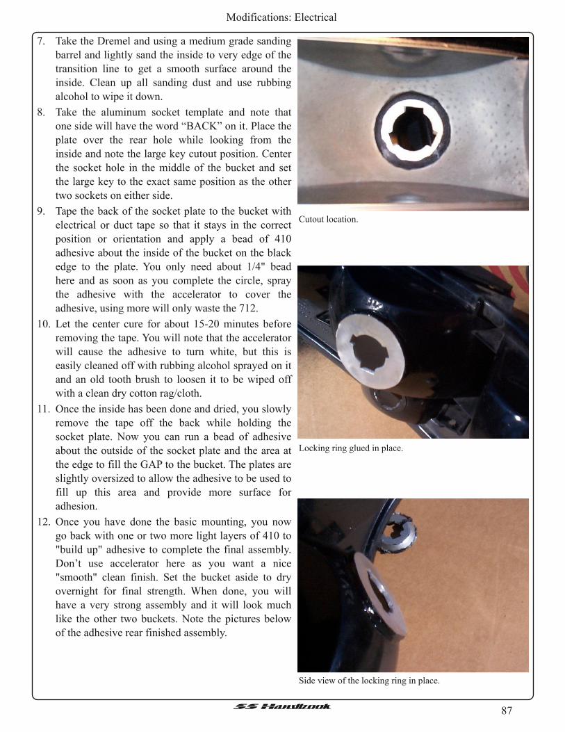
87SSHandbook
Modifications: Electrical
7. Take the Dremel and using a medium grade sanding
barrel and lightly sand the inside to very edge of the
transition line to get a smooth surface around the
inside. Clean up all sanding dust and use rubbing
alcohol to wipe it down.
8. Take the aluminum socket template and note that
one side will have the word “BACK” on it. Place the
plate over the rear hole while looking from the
inside and note the large key cutout position. Center
the socket hole in the middle of the bucket and set
the large key to the exact same position as the other
two sockets on either side.
9. Tape the back of the socket plate to the bucket with
electrical or duct tape so that it stays in the correct
position or orientation and apply a bead of 410
adhesive about the inside of the bucket on the black
edge to the plate. You only need about 1 /4" bead
here and as soon as you complete the circle, spray
the adhesive with the accelerator to cover the
adhesive, using more will only waste the 712.
1 0. Let the center cure for about 1 5-20 minutes before
removing the tape. You will note that the accelerator
will cause the adhesive to turn white, but this is
easily cleaned off with rubbing alcohol sprayed on it
and an old tooth brush to loosen it to be wiped off
with a clean dry cotton rag/cloth.
11 . Once the inside has been done and dried, you slowly
remove the tape off the back while holding the
socket plate. Now you can run a bead of adhesive
about the outside of the socket plate and the area at
the edge to fill the GAP to the bucket. The plates are
slightly oversized to allow the adhesive to be used to
fill up this area and provide more surface for
adhesion.
1 2. Once you have done the basic mounting, you now
go back with one or two more light layers of 410 to
"build up" adhesive to complete the final assembly.
Don’t use accelerator here as you want a nice
"smooth" clean finish. Set the bucket aside to dry
overnight for final strength. When done, you will
have a very strong assembly and it will look much
like the other two buckets. Note the pictures below
of the adhesive rear finished assembly.
Cutout location.
Locking ring glued in place.
Side view of the locking ring in place.

88SSHandbook
Modifications: Electrical
Exposed areas masked off prior to painting.
1 3. If you do not plan on installing reflective film(s),
you will need to cover the inside area of the bucket
in reflective type aluminum spray paint to cover the
black adhesive. Once two or three "light coats" are
sprayed over the inside, it will look and reflect light
like the other two associated bulb reflectors
sections.
1 4. To complete the socket installation, mask off and
paint the rear reflector housing and use a good
quality gloss black spray paint to cover the adhesive
and exposed aluminum of the socket plate. Note the
following pictures.
When installed, you will have to press down firmly
while rotating the socket to its correct position. Look
closely at the other two brake socket backs when
installing the bucket and set the center one to the
"exact" same position. This again is very important here
to have the bulb filaments vertical in the reflector
housing.
When completed, the combination of the socket
plate and new deep type socket will now match the
focus characteristics of the other two brake/turn signal
lights making them all match in pattern and brightness.
Dreaded Dim bulb effect is now eliminated!
Bucket now ready for next stage ofmodification.
Bucket now ready for next stage ofmodification.

89SSHandbook
Modifications: Electrical
Tail Light, Lens Bucket Modification
A viable way to squeeze more light power out of
the rear light system is to improve the reflective and
focus properties of the lens reflector assembly
(buckets). The red plastic lens can be separated from the
bucket assembly by removing the red lens. It is not
permanently sealed as a black rubbery putty is used
along with a few plastic tab clips to hold the assembly
together. Using a small flat knife, you can easily able to
separate the lens from the bucket and remove the old
sealant and clean up the joining channels for later
reassembly. Once separated the assemblies you will be
disappointed in the overall quality and construction of
the reflectors. Silver reflective paint sprayed over the
plastic reflectors with small star impressed dimples for
refraction is all that is in there. The paint can literally be
wiped off with your fingers and did not have very good
"reflective" properties on direct visual inspection.
Below are some basic pictures of the before and after on
a reflector bucket.
You can plainly see silver spray paint that does not
reflect light all that well (even with a flash here) and a
small strip of aluminum separating the bottom backup
light housing. The silver paint will come off readily and
easily with a rag and some Isopropyl alcohol. Also note
the different sizes, directions and angles that the three
brake/turn signal bulb bucket housing were focused or
aimed. Filament position also plays a role in the lamp
reflector efficiency. Below is an "after" picture with the
Chrome/Mylar mirror reflector tape installed.
Junky factory silver paint.
Chrome / Mylar tape applied.
The mirror reflective tape used in this write-up is
made by 3M and comes in various sizes and rolls.
Different thicknesses were used to follow the molded
bucket as closely as possible and temperature resistance
is important here as well.
Depending on what your pocket book can stand look
for the reflective tape at 50-80°C ratings.
Outside shot of the same lens bucket getting ready
to have the red filter lens placed back on it.
Outside shot of a finished bucket.

90SSHandbook
Modifications: Electrical
Light Measurements?
Watts are not light. Watts are used to measure electrical power and in lighting systems is used in
conjunction with a term called Efficacy. Efficacy = Lumens/Watts for a ratio of light output to electrical
power input. This measures how efficient a system is as to how much power is consumes. Different types of
light use different amounts of power and have different costs to operate.
› Quantity of light is measured in Lumens, Footcandles, and Candlepower.
Lumen: Measure ofLight Flux or "volume".Footcandles: Density ofLight Striking a Surface (level of illumination)Candlepower: Intensity ofLight
Power Output/Footcandle test results:
The following bulb and lens assembly lumen power survey was conducted using a General Electric Model
214 (color and cosine corrected) light meter with direct measurement readout in footcandles. Reflector
upgrade was accomplished using hi-grade chrome/mylar reflector tape used for industrial photocell detector
applications.
Stanley #3496 LENS OUTPUT measurements in Footcandles
Before bucket MOD:
Tail Light, Light Bulbs
Output inFootcandles
OutboardDriverMiddle
Inboard InboardPassengerMiddle
Outboard
Parking Light 50 50 50 50 50 50
Brake Light 220 195 240 240 190 215
Backup Backup
Stock # 2057 750 750
Krypton#3496
940 930
Output inFootcandles
OutboardDriverMiddle
Inboard InboardPassengerMiddle
Outboard
Parking Light 60 75 60 65 75 60
Brake Light 280 300 300 300 300 275
Backup Backup
Stock # 2057 900 910
Krypton#3496
1000 1000
After bucket MOD:

91SSHandbook
Modifications: Electrical
Approximate average CP upgrade in performance
[Stock reflector bucket]
1 Brake filament from 2057 to #3496 is 30%
2 Parking filament from 2057 to #3496 is 50%
[Modified reflector bucket]
1 Brake filament using #3496 is 'additional' 34% with most improvement in center lamp bucket output.
2 Park filament using #3496 is 'additional' 20% with most improvements in center lamp bucket output.
3 Smallest increase was on outside lens bucket(s) due to smaller physical size reflector.
So, in short, you get more candlepower output for close to the same wattage used on upgrading to #3496,
but when "combined" with reflector upgrade as well you get another 30% increase with much brighter
(+100%) backup lights and center bulb output. Rear lamps appear to display multi-faceted lens characteristics
as opposed to solid 'dull' lamp illumination. This look is considerably more eye appealing and distinct.
Backup light output displayed the most of all with a whopping 100% improvement!
You can now get the "halogen" hi-power bulb look without the problems of wiring harness, brake switch,
turn signal switch ratings and overheating sockets. Now, it will take some patience and a few hours to do the
whole job. One of the interesting "side effects" is the viably appealing "jeweled" effect provided by the
internal red lens itself. This is near invisible using the stock reflectors but when enhanced to focus the bulbs
better the refraction through the red lens now looks like it has facets or a jeweled effect!

92SSHandbook
Modifications: Exhaust
Exhaust
The fact is most cars are leaving horsepower on the table. We show you how to get it back.
From the February, 2009 issue of Super Chevy
Photography by Various Manufacturers
All contributors: David Vizard
For me the first really serious look at how to muffle a high performance race engine without losing a
significant amount of power started in 1980 when I built a 4001b-ft, 404hp 350 to replace the very lame
158hp 305 in my California-spec Pontiac Trans Am. Having worked very hard to build a pump gas fueled
engine (gas was really bad in those days), that would cross the 400 hp barrier, I was very disappointed to find
that, regardless ofwhat mufflers were used, the output dropped by some 20 Ib-ft and 25 hp. Having had some
experience designing a no-loss system for the original style British Mini Coopers, I felt confident I could pull
off the same stunt for significantly bigger V-8 engines. The result, aided by an acoustics expert friend, was the
Sonic Turbo. This design went on to be manufactured by Cyclone (now a division ofWalker/Dynomax). After
the smoke cleared from a big muffler shootout (done at Gale Banks facility and published by Hot Rod
magazine), a pair of 2.25-inch Sonic Turbos (the 2.5-inch ones were still a couple of months off) sunk
everybody else's 2.5-inch items. This, it seemed, was just what the hot rod fraternity wanted and they sold by
the hundreds of thousandths. That was good, but more importantly; it appeared to spark the industry into
aggressively pursuing significantly more functional mufflers and exhaust systems. The result is that 20-some-
years later, all the necessary components to build a highly effective, no-loss system are at hand, and not
necessarily that much money either. All that appears to be lacking is widespread know-how as to what is
needed to achieve this happy state of affairs. As of now, we are going to make a start on putting that right.
Simple Steps to Success
Although the mode of function of an exhaust system is complex, it is not (as so often is believed, even by
many pro engine builders) a black art. To help appreciate the way to get the job done I will go through the
process of selecting exhaust system components for a typical high performance V-8 in a logical manner from
header to tail pipe. Although the entire exhaust
functions as a system, we can, for all practical purposes,
break down many of the requirements that need to be
met into single entities. Fig. 1 details the order of
business. But before making a start, it is a good idea to
establish just why getting the exhaust correctly spec'd
out is so important. This will allow realistic goals,
improved component choice, and a more functional
installation. The V-8 engines we typically modify for
increased output are normally categorized as four-cycle
units. Although pretty much the case for a regular street
machine, this is far from being the case for a high
performance race engine. If we consider a well-
developed race engine, the usual induction,
compression, expansion (power stroke) and exhaust
cycles have a fifth element added (Fig. 2). With a race
cam and a tuned-length exhaust system, negative
pressure waves traveling back from the collector will
This More Performance LS6 relied heavily on the
effectiveness of the Nextel Cup-style Kook's long 4-into-2-
short-into-1 headers to bring the entire power production
program together. The result: 726 horsepower!
Exhaust Science Demystified

93SSHandbook
Modifications: Exhaust
scavenge the combustion chamber during the
exhaust/intake valve overlap period (angle 5 in Fig. 2).
To understand the extent to which this can increase an
engine's ability to breathe, let's consider the cylinder
and chamber volumes of a typical high-performance
350 cubic-inch V-8. Assuming for a moment no flow
losses, the piston traveling down the bore will pull in
one-eighth of 350 cubic inches. That's 43.75 cubic
inches, or in metric, 717cc. If the compression ratio is
say 11 : 1 , the total combustion chamber volume above
this 717cc will be 71 . 7cc. If a negative pressure wave
sucks out the residual exhaust gases remaining in the
combustion chamber at TDC, then the cylinder, when
the piston reached BDC, will contain not just 717 cc
but 717 + 71 . 7 cc = 788.7 cc. The result is that this
engine now runs like a 385 cubic inch motor instead of
a 350. That scavenging process is, in effect, a fifth
cycle contributing to total output.
But there are more exhaust-derived benefits than just chamber scavenging. Just as fish don't feel the
weight of water, we don't readily appreciate the weight of air. Just to set the record straight, a cube of air 100
feet square will weigh 38 tons! If enough port velocity is put into the incoming charge by the exhaust
scavenging action, it becomes possible to build a higher velocity throughout the rest of the piston initiated
induction cycle. The increased port velocity then drives the cylinder filling above atmospheric pressure just
prior to the point of intake valve closure. Compared with intake, exhaust tuning is far more potent and can
operate over ten times as wide an rpm band. When it comes to our discussion of exhaust pipe lengths it will be
important to remember this.
At this time a few numbers will put the value of exhaust pressure wave tuning into perspective. Air flows
from point A to point B by virtue of the pressure difference between those two points. The piston traveling
down the bore on the intake stroke causes the pressure difference we normally associate with induction. The
better the head flows the less suction it takes to fill (or
nearly fill) the cylinder. For a highly developed two-
valve race engine the pressure difference between the
intake port and the cylinder caused by the piston
motion down the bore, should not exceed about 10-12
inches of water (about 0.5 psi). Anything much higher
than this indicates inadequate flowing heads. For more
cost-conscious motors, such as most of us would be
building, about 20-25 inches of water (about 1 psi) is
about the limit if decent power (relative to the budget
available) is to be achieved. From this we can say that,
at most, the piston traveling down the bore exerts a
suction of 1 psi on the intake port Fig. 3 .
The exhaust system on a well-tuned race engine
can exert a partial vacuum as high as 6-7 psi at the
Fig 2 A high-performance or race engine relies heavily on an
exhaust-driven induction cycle (the fifth cycle) to achieve
those 100 percent-plus volumetric efficiency figures.
Fig 3 This comparison between the piston's suction on the
intake compared with the exhausts indicates just how much
potential there is in exhaust tuning.

94SSHandbook
Modifications: Exhaust
exhaust valve at and around TDC. Because this occurs during the overlap period, as much as 4-5 psi of this
partial vacuum is communicated via the open intake valve to the intake port. Given these numbers you can see
the exhaust system draws on the intake port as much as 500 percent harder than the piston going down the
bore. The only conclusion we can draw from this is that the exhaust is the principal means of induction, not
the piston moving down the bore. The result of these exhaust-induced pressure differences are that the intake
port velocity can be as much as 100 ft./sec. (almost 70 mph) even though the piston is parked at TDC! In
practice then, you can see the exhaust phenomenon makes a race engine a five-cycle unit with two
consecutive induction events. With the exhaust system's vital role toward power production established, it will
be easy to see that understanding how to select and position the right combination of headers, resonators,
routing pipes, crossovers and mufflers will be a winning factor. This will be especially so if mufflers are
involved in the equation. I first started putting out the word on how to build no-loss systems as much as 20
years ago and I am somewhat surprised that it is still commonly believed that building power and reducing
noise are mutually exclusive. Historically, this has largely been so, but building a quiet system that allows the
engine to develop within 1 percent of its open exhaust power is entirely practical. Be aware that knowing what
it takes in this department can easily deliver a 40-plus hp advantage over your less-informed competition.
Headers -- Primary Pipe Diameters
Big pipes flow more, so is bigger better? Answer: absolutely not. Primary pipes that are too big defeat our
quest for the all-important velocity-enhanced scavenging effect. Without knowledge to the contrary, the
biggest fear is that the selected tube diameters could be too small, thereby constricting flow and dropping
power. Sure, if they are way under what is needed, lack of flow will cause power to suffer. In practice though
it is better, especially for a street-driven machine, to have pipes a little too small rather than a little too big. If
the pipes are too large a fair chunk of torque can be lost without actually gaining much in the way of top-end
power. At this point determining primary tube diameters is starting to look like a tight wire act only avoidable
by trial and error on the dyno.
Fortunately, a little insight into what it is we are
attempting to achieve brings about some big-time
simplification. Our goal is to size the primary pipes to
produce optimum output over the rpm range of most
interest. The rate exhaust is dispensed with, and
consequently, the primary pipe velocity, is strongly
influenced by the port's flow capability at the peak
valve lift used. From this premise it has been possible
to develop a simple correlation between exhaust port-
flow bench tests and dyno tests involving pipe diameter
changes. This has brought about the curves shown in
the graph Fig. 4 which allow primary sizing close
enough to almost eliminate the need for trial-and-error
dyno testing.
Primaries for Nitrous Use
Since nitrous injection is so popular, it's worth
throwing in the changes needed to optimize with the
nitrous on. For a typical race V-8 the area of the
primary pipe needs to increase about 6-7 percent for
every 50 hp worth of nitrous injected. For street
Fig 4 This chart applies to normally aspirated engines. For
street headers, where low-speed torque is of prime
importance (especially with a stock converter and high rear
end gears), use the lower line to select the appropriate
primary size. For hot street machines having reasonably big
cams and decent compression, use the middle line to size the
primary. For race engines, use the top line. If nitrous is
involved, check out the nitrous header section.
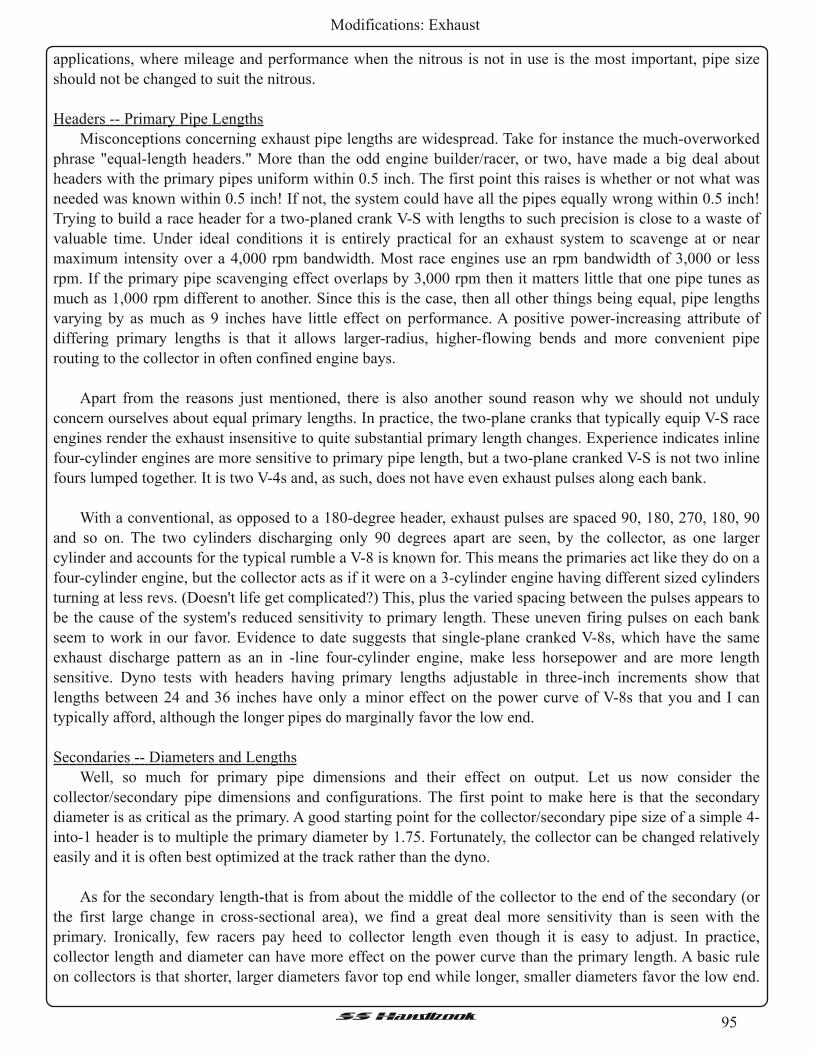
95SSHandbook
Modifications: Exhaust
applications, where mileage and performance when the nitrous is not in use is the most important, pipe size
should not be changed to suit the nitrous.
Headers -- Primary Pipe Lengths
Misconceptions concerning exhaust pipe lengths are widespread. Take for instance the much-overworked
phrase "equal-length headers." More than the odd engine builder/racer, or two, have made a big deal about
headers with the primary pipes uniform within 0.5 inch. The first point this raises is whether or not what was
needed was known within 0.5 inch! If not, the system could have all the pipes equally wrong within 0.5 inch!
Trying to build a race header for a two-planed crank V-S with lengths to such precision is close to a waste of
valuable time. Under ideal conditions it is entirely practical for an exhaust system to scavenge at or near
maximum intensity over a 4,000 rpm bandwidth. Most race engines use an rpm bandwidth of 3,000 or less
rpm. If the primary pipe scavenging effect overlaps by 3,000 rpm then it matters little that one pipe tunes as
much as 1 ,000 rpm different to another. Since this is the case, then all other things being equal, pipe lengths
varying by as much as 9 inches have little effect on performance. A positive power-increasing attribute of
differing primary lengths is that it allows larger-radius, higher-flowing bends and more convenient pipe
routing to the collector in often confined engine bays.
Apart from the reasons just mentioned, there is also another sound reason why we should not unduly
concern ourselves about equal primary lengths. In practice, the two-plane cranks that typically equip V-S race
engines render the exhaust insensitive to quite substantial primary length changes. Experience indicates inline
four-cylinder engines are more sensitive to primary pipe length, but a two-plane cranked V-S is not two inline
fours lumped together. It is two V-4s and, as such, does not have even exhaust pulses along each bank.
With a conventional, as opposed to a 180-degree header, exhaust pulses are spaced 90, 1 80, 270, 1 80, 90
and so on. The two cylinders discharging only 90 degrees apart are seen, by the collector, as one larger
cylinder and accounts for the typical rumble a V-8 is known for. This means the primaries act like they do on a
four-cylinder engine, but the collector acts as if it were on a 3-cylinder engine having different sized cylinders
turning at less revs. (Doesn't life get complicated?) This, plus the varied spacing between the pulses appears to
be the cause of the system's reduced sensitivity to primary length. These uneven firing pulses on each bank
seem to work in our favor. Evidence to date suggests that single-plane cranked V-8s, which have the same
exhaust discharge pattern as an in -line four-cylinder engine, make less horsepower and are more length
sensitive. Dyno tests with headers having primary lengths adjustable in three-inch increments show that
lengths between 24 and 36 inches have only a minor effect on the power curve of V-8s that you and I can
typically afford, although the longer pipes do marginally favor the low end.
Secondaries -- Diameters and Lengths
Well, so much for primary pipe dimensions and their effect on output. Let us now consider the
collector/secondary pipe dimensions and configurations. The first point to make here is that the secondary
diameter is as critical as the primary. A good starting point for the collector/secondary pipe size of a simple 4-
into-1 header is to multiple the primary diameter by 1 .75. Fortunately, the collector can be changed relatively
easily and it is often best optimized at the track rather than the dyno.
As for the secondary length-that is from about the middle of the collector to the end of the secondary (or
the first large change in cross-sectional area), we find a great deal more sensitivity than is seen with the
primary. Ironically, few racers pay heed to collector length even though it is easy to adjust. In practice,
collector length and diameter can have more effect on the power curve than the primary length. A basic rule
on collectors is that shorter, larger diameters favor top end while longer, smaller diameters favor the low end.

96SSHandbook
Modifications: Exhaust
Except for the most highly developed engines, many
collectors I see at the track are too large in diameter and
either too short, or of excessive length. For a motor
peaking at around 6,000-8,500 rpm, a collector length of
10-20 inches is effective.
Getting secondary lengths nearer optimal can be
worth a sizable amount of extra power as Fig. 5 shows.
If you want to bump up torque at the point a stock
converter starts to hook up the engine, you may want a
secondary as long as 50 inches but something between
about 10 and 24 is more normal. The shorter of these
two lengths would be appropriate for an engine peaking
at about 8,500 rpm whereas the longer length would be
best for an engine that peaked at about 4,800- 5,000
rpm.
Mufflers -- Two Golden Rules to Avoid Power Loss
Inappropriate muffler selection and installation
(which appears so for better than 90 percent of cases)
will, in a very effective manner, negate most of the
advantages of system length/diameter tuning. The
question at this point is what does it take to get it right
and how much power are we likely to lose if the system
is optimal? The quick and dirty answers to these
questions are "not much" and "zero." This next
sentence is the key to the whole issue here, so pay
attention. To achieve a zero-loss muffled high
-performance race system we need to work with the
two key exhaust system factors in total isolation from
each other. These two factors are: the pressure wave
tuning from length/diameter selection, and minimizing
backpressure by selecting mufflers of suitable flow
capacity for the application. If we do this then a quiet
(street-legal noise levels) zero-loss system on a race car
is totally achievable without a great deal of effort on
anybody's part. Ultimately, it boils down to nothing
more than knowledgeable component selection and
installation, so let's look at what it takes in detail.
Muffler Flow Basics
We select carbs based on flow capacity rather than
Fig 5 Here are the gains, as measured at the rear wheels,
produced by the collector extension arrowed in the nearby
photo.
Fig 6 In terms of flow, an inlet, muffler and outlet that
appears to the airflow to look like number 1 is what is
needed. A real-world muffler (number 2) does not look like
number 1 , but number 4. This shows that the muffler, not the
pipe, is the usual restriction. Some race mufflers actually
have a core flow greater than the in/out pipe and look like
number 5.

97SSHandbook
Modifications: Exhaust
size because engines are flow sensitive, not size sensitive. This being so, why should the same not apply to the
selection of mufflers? The answer (and here I'd like muffler manufactures to please note) is that it should, as
the engine's output is influenced minimally by size but dramatically by flow capability. Buying a muffler
based on pipe diameter has no performance merit. The only reason you need to know the muffler pipe size is
for fitment purposes. The engine cares little what size the muffler pipe diameters are but it certainly does care
what the muffler flows and muffler flow is largely dictated by the design of the innards. What this means is
that the informed hot rodder/engine builder should select mufflers based on flow, not pipe size. A study of Fig.
6 will help to give a better understanding as to how the design of the muffler's core, not the pipe size, dictates
flow. Let's start by viewing a muffler installation as three distinct parts. In Fig. 6, drawing number 1 , these are
the in-going pipe, the muffler core and the exit pipe. Drawing number 2 shows a typical muffler which has,
due to a design process apparently unaided by a flow bench, core flow significantly less than an equivalent
length of pipe the size of the entry and exit pipe. Because the core flow is less than the entry and exit pipe
then the engine "sees" the muffler as if it were a smaller and consequently more restrictive pipe as per
drawing number 4. If the core has more flow than the equivalent pipe size, as in drawing number 5, it appears
larger than the entry and exit pipe. Result: the muffler is seen by the engine as a near zero restriction. A
section of straight pipe the length of a typical muffler, rated at the same test pressure as a carb (10.5 inches of
mercury), flows about 11 5 cfm per square inch. Given this flow rating, we will see about 560 cfm from a 2.5-
inch pipe. If we have a 2.5-inch muffler that flows 400 cfm, the engine reacts to this just the same as it would
a piece of straight pipe flowing 400 cfm. At 115 cfm per square inch, that's the equivalent to a pipe only 2.1
inches in diameter. This is an important concept to appreciate. Why? Because so many racers worry about
having a large-diameter pipe in and out of the muffler. This concern is totally misplaced, as in almost all but a
few cases, the muffler is the point of restriction, not the pipe. The fact that muffler core flow is normally lower
than the connecting pipe can be offset by installing something with higher flow, such as a 4-inch muffler into
an otherwise 2.75-inch system
Muffler Flow - - How Much is Needed?
The first point to appreciate here is that optimally-sized collectors/secondary pipes are not sized so as to
meet the engine's flow requirement, but more by the need to produce the desired pressure wave
characteristics. For instance, a 700hp engine may have a dyno-optimized 3.75-inch diameter collector. This
diameter, in conjunction with the length used, results in the system "tuning in" at the desired rpm. But from
the standpoint of flow, a 3-inch pipe from each bank would be capable of handling all of such an engine's flow
requirements.
Without data to the contrary, it seems safe to assume that the more a muffler flows, the better. This,
fortunately, is not so and here's why. Increasing muffler flow unlocks potential engine power. Once all the
potential power is unlocked, further increases in exhaust system flow will not produce any further benefits in
terms of power. But what may be good for power may not be good for noise as any excess flow capability can
lead to a noisier system. From this we can conclude that too much muffler flow serves no useful purpose and
possibly costs more money than was really necessary. The trick here is to use just the right amount ofmuffler,
no more and certainly no less. This allows the full power potential of the engine to be realized at the lowest
cost without undue compromise in terms of noise. Now the question is how much flow is enough?
Some years ago, in anticipation of the fact that eventually almost all race cars would need to be equipped
with mufflers, I embarked on a series of tests to establish what a race engine's minimum flow threshold was.
Initially, such tests looked easy but, to get meaningful results, it was necessary, as far as possible, to isolate the
effects of flow from the effects of pressure wave tuning. This can be done with a pressure wave termination
chamber more commonly known as a resonator box. Knowing when and how to use a resonator box can be a

98SSHandbook
Modifications: Exhaust
very important part of building a high
-performance system and we will look at
these shortly to see the role they play.
For now, let us look at some flow-
oriented test results. In Fig. 7 you will
see the results of tests run on a number of
engines of various types. The only
common element of significance between
these engines was the use of a cam with
290 degrees or more of seat (advertised)
duration. As you can see, the trend is that
as flow is added to an initially flow-
restricted engine, power increases rapidly
at first then gains tail off. Once the
available flow exceeds about 2.2 cfm per
hp, the gains possible by increasing
muffler capacity drop to less than 1
percent. Knowing that 2.2 cfm per open-
pipe hp means zero loss from
backpressure allows us to determine how
much muffler flow your engine needs. Just make a
reasonable estimate of its open exhaust power potential
and multiply by 2.2. For instance, a V-8 making 500
horsepower on open exhaust will require 500 x 2.2 =
1100 cfm. Two 550-cfm mufflers will get the job done
and contain the backpressure induced power loss to 5
horsepower or less. With mufflers rated in cfm, see how
easy making an appropriate choice gets?
Pressure Waves
With muffler flow requirements out of the way we
can move on to methods of applying suitable capacity
mufflers to the "system" without needless disruption of
length -induced pressure wave tuning. Probably the
best way to ease into this somewhat complex subject is
to consider some of the published muffler test results
done in recent years. These tests appeared to have
shown that, sometimes, lower flow mufflers inducing at
least some backpressure were required to make best
power. In all such tests that I have studied, the
conclusions (as opposed to the tests) were invalid.
There turns out to be several reasons for this and all are
relevant to building a near zero-loss exhaust system.
The first point canceling the supposed validity of back-
to-back test results is due to the varied internal designs
seen amongst the test pieces Fig. 8. Many mufflers are
made up of a number of interconnected chambers
The line rising from left to right shows muffler flow versus the percent of
maximum power retained compared with open-pipe power. Once the flow
reaches 2.2 cfm per hp, the output seen is as per open pipe output. The line
descending left to right shows the typical backpressure seen. At 2.2 cfm per
hp, the backpressure should be down to as little as 0.2 psi (a little less than
0.5 of an inch ofmercury).
Fig 8 Understanding the concept outlined here is vital to
understanding how different styles ofmufflers affect the
apparent tuned length.

99SSHandbook
Modifications: Exhaust
having varying degrees of access ease by the exhaust. Others are of the "glass pack" variety. These types
represent opposite ends of a spectrum and have a substantially differing response to arriving pressure waves.
When we dealt with collector length it was emphasized that it was, in most cases, more critical than the
primary pipe lengths. Adding a muffler (even one with zero backpressure) to a system with already optimized
lengths can alter the pressure wave response such that the tuning is now out of phase with what is required
and as a result, power drops. The trick here is to install mufflers such that they don't alter the tuned lengths of
the system. Let us assume that the test muffler is attached directly to the end of the collector. A pressure wave
is reflected either at the end of the exhaust pipe or when a sizable increase in cross-sectional area occurs.
Open chambered mufflers such as Flowmasters often appear to the pressure wave much the same as the end of
the pipe. This means the pressure waves see no change in length and reflection occurs largely as it did prior to
the fitment of the muffler.
A glass pack muffler can act significantly different.
It does not appear as a pipe end but as a substantial
increase in collector length. Result: a reduction of
power even though there is no measurable
backpressure involved. From this we can see that many
comparative muffler tests were in fact "pseudo pipe-
length" tests. Although many invalid conclusions were
drawn, these tests still demonstrated some important
facts. The most important is that the engine's needs in
terms of flow and pressure wave length tuning must be
isolated, one from the other. This is easy to do by
means of the pressure wave termination box (resonator
box) mentioned earlier. Incorporating a resonator box
into a system produces a layout along the lines seen in Fig. 9. With enough volume, the resonator box makes
everything down stream appear invisible to the header's primary- and secondary-tuned lengths. With a flow
capability of 2.2 cfm or more, the muffler appears virtually invisible from a flow standpoint. As a result, we
have a muffled system that produces virtually the same power as an open exhaust.
Cross Overs and Balance Pipes
The object of the entire muffler tech so far discussed is to end up with an acceptably quiet system;
otherwise the point of the exercise is lost. By using no more muffler flow than needed we are giving whatever
mufflers are selected the best chance of doing the job. Unfortunately, mufflers can be a little inconsistent and
unpredictable in terms of noise suppression from one engine type to another. Situations involving high
compression ratios and long-period cams are usually more demanding in terms of noise reduction. Big cubic
inches, shorter cams, and lower compression ratios are easier to muffle. The biggest problem in this area is
knowing whether or not a possible combination is quiet enough. If you hit the Dynomax web site you can hear
chassis dyno tests of a wide variety ofmufflers (including stock) on an extensive range of vehicles.
Be aware that how the system is installed can also affect the sound level, especially in the vehicle's
interior. Do not have the tail pipe ending under the car, as the bodywork will act as a sound box in much the
same way as a guitar body. Either have them go all the way to the rear, with down turned exit pipes angled
slightly in towards each other, or have side exits aimed 45 degrees to the ground. As far as power is
concerned, tail pipe length after the mufflers has no measurable effect on the power if a large change in cross
section is present up stream (toward the motor) of the tail pipe. An open-type muffler, or a resonator box,
Fig 9 Follow the system construction guidelines shown here
and you will be pretty much assured of a zero-loss exhaust
system.
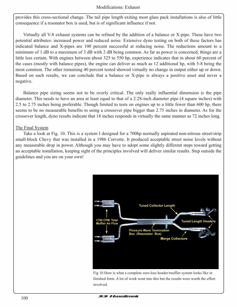
100SSHandbook
Modifications: Exhaust
provides this cross-sectional change. The tail pipe length exiting most glass pack installations is also of little
consequence if a resonator box is used, but is of significant influence if not.
Virtually all V-8 exhaust systems can be refined by the addition of a balance or X-pipe. These have two
potential attributes: increased power and reduced noise. Extensive dyno testing on both of these factors has
indicated balance and X-pipes are 100 percent successful at reducing noise. The reductions amount to a
minimum of 1 dB to a maximum of 3 dB with 2 dB being common. As far as power is concerned, things are a
little less certain. With engines between about 325 to 550 hp, experience indicates that in about 60 percent of
the cases (mostly with balance pipes), the engine can deliver as much as 12 additional hp, with 5-8 being the
most common. The other remaining 40 percent tested showed virtually no change in output either up or down.
Based on such results, we can conclude that a balance or X-pipe is always a positive asset and never a
negative.
Balance pipe sizing seems not to be overly critical. The only really influential dimension is the pipe
diameter. This needs to have an area at least equal to that of a 2.2S-inch diameter pipe (4 square inches) with
2.5 to 2.75 inches being preferable. Though limited to tests on engines up to a little fewer than 600 hp, there
seems to be no measurable benefits to using a crossover pipe bigger than 2.75 inches in diameter. As for the
crossover length, dyno results indicate that 1 8 inches responds in virtually the same manner as 72 inches long.
The Final System
Take a look at Fig. 1 0. This is a system I designed for a 700hp normally aspirated non-nitrous street/strip
small-block Chevy that was installed in a 1986 Corvette. It produced acceptable street noise levels without
any measurable drop in power. Although you may have to adopt some slightly different steps toward getting
an acceptable installation, keeping sight of the principles involved will deliver similar results. Step outside the
guidelines and you are on your own!
Fig 10 Here is what a complete zero-loss header/muffler system looks like in
finished form. A lot ofwork went into this but the results were worth the effort
involved.

101SSHandbook
Modifications: Exhaust
SOME HEAVY-DUTY QUOTES FROM ENGINE MASTERS WINNERS
John Kaase: "I used a straight-through glass pack muffler design specifically because of the high-flow
they can deliver. My dyno testing left no doubt as to how important collector length was and that a straight-
through glass pack contributes to that length. By getting the collector/muffler length right, which in our case
was about 40 inches, the torque at 3,500 was increased substantially. That gain is probably what won the
Engine Masters deal for me the first time. I have seen an incorrect length along with less than the critical
minimum flow cost 40 hp. Short change efforts on the collector/secondary and it will short change you."
Joe Sherman: "If you are building a serious performance system, then assuming you have a near-optimal
header set-up, the place that is most critical when it comes to avoiding power loss is from the collector back.
Also, don't be fooled into thinking that big tailpipes contribute to power. In all my years of dyno testing, I
never have seen that work. For me, the straight-through Magnaflows when used as part of the collector length,
show only very small losses in power over an open pipe. It's all about the right length and sufficient flow. I
have seen mistakes in this area cost 85 horsepower."
GOT CATS--NEED FLOW?
If, to stay legal your exhaust system must run catalytic converters, then the possibility of loosing power
goes up dramatically, but it certainly does not mean the game is lost. The first rule of thumb here is if the cats
must be in the original position, use the highest-flow components that can be physically installed. For high
-flow, high performance cats, one of the first places I would try would be Random Technologies. Some of this
company's key employees drag race late model-street legal machines and are serious about performance. Also
in the business of marketing genuine hi -flow cats and cat systems are Walker (Dynomax), Magnaflow,
Dynatech and, for a number of specialized truck installations, Gale Banks. These are not the only ones, but
they are all the companies of which I have experienced the no-nonsense functionality of their products. If the
position of the cats can be moved to such an extent that the length going into the cats represent the secondary
tuned length, then we find that to an extent, the cat, if large enough, can, in part, act as a resonator box.
Moving the cats to a more favorable position then is rule number 2 when cats must be used. Rule number 3 is
that if there is room to put a crossover or an X-pipe before the cats, then that's almost always the best place.
Anything after the cats will drop the sound level but is unlikely to increase power unless the flow of the
mufflers you chose was significantly short ofwhat was needed.
High-Tech Collectors
Technology to make a good header has been around for 30-plus years. These days, making a top-notch
header is very much a question of refinements to eek out whatever potential may be remaining. One area of
research that has paid dividends in the past decade is in the collector design. Example number 1 on a system
built by Kook's Headers is a 4-into-1 merge collector (arrowed). Dyno testing this type of collector, versus a
regular parallel one, shows that the merge collector tends to pull up torque from the lower speed range with
ever decreasing amounts, thus delivering a fatter torque curve but not necessarily any more peak hp. Another
header/collector worthy of note (our example is again from Kook's) is the type shown in photo number 2. This
is much favored by Busch and Nextel Cup engine builders. Essentially it is a long 4-into-ashort-2-into-1
system. The parts that go to make up the system between points A and B are shown in the top right hand
corner of number 2. About 10 years ago, Flowmaster introduced a collector that converted a regular 4-into-1
system into the system seen here. This was my introduction to testing this configuration of collector. The dyno
indicated only marginal gains in peak power. Like the merge collector, this collector style fattened up the
torque curve, but usually to a greater extent.

102SSHandbook
Modifications: Intake Alternatives
Intake Alternatives
Before doing any of the following procedures, be sure of exactly what you want first. There are many
options available but these are the cheapest.
• Chrome Exhaust Intake – Uses a chrome exhaust tip to replace First Base.• Flat Panel High Flow Filter – Replace the stock filter with an aftermarket high flow replacement.• Home Plate and First Base Delete – Home Plate is a “home plate” shaped, hence the name, air baffle sits
on top of the engine with “Fuel Injected V8” embossed on the top. The rectangular baffle that sits in-
between the intake and the air box called First Base. Both baffles are used reduce engine noise and to
quiet down the LT1 for the laid-back folks. Some people like things loud with more power. Along with
decreasing the noise, they also decrease the horsepower. Therefore, if you want an easy way to gain a few
ponies, delete them both. See Home Plate Removal and First Base Removal for more detail.
• Sewer Pipe Intake – Another cheap and simple intake.• Swiss Cheese Air Box – One way of letting your air box breathe better.Some of the other, more expensive modifications are:
› R.A.I.S.S. – http://www.impalaperformance.com
Places the MAF sensor and filter directly onto the throttle body for quicker response
Encloses the filter to promote cold air
Air Force 1 option supplemented by the new Air Force II that is a shroud that directs the airflow through
the grill and over the radiator
› RAMMIT Intake System
Forced induction from underneath car
› K & N Generation 2 Cold Air System
Replaces “First Base” and encloses the cone filter to promote cold air into intake
› SLP RamAir System with Hood
This hood coils the intake around to the top of the throttle body, to work in conjunction with the SLP Ram
Air hood.
› SLP Cold Air Intake
Much like the Gen 2 form K&N but has 2 cone filters and no heat shield
› SSRI - Super Stealth Ram Intake
Much like the R.A.I.S.S. but shroud is not as wide.
Chrome Exhaust Intake
Materials:
• A 3.5" chromed exhaust pipe cut to 13".• A 2"3" section of 3.5" ID rubber hose. Check with a local heavy truck supply store for Gates hoses.
"GATES Green Strip 3 1/2" I.D. (89 mm)", P/N 24256, seems to work great. You can also get a "no hubcoupler" from a hardware store. Any sort of heatresistant rubber connector will work fine.
• Two pipe clamps to secure the tubing to the MAF and the pipe.Procedure:
1 . Take the air box lid off the air box base, remove the filter, and set them aside.
2. Unscrew the Torx head nut/bolt on the fender well.

103SSHandbook
Modifications: Intake Alternatives
Tools:
• Flat head screwdriverProcedure:
1 . Loosen the hose clamps holding First Base to the
MAF sensor and pull apart.
2. Loosen the hose clamp holding the other side of
First Base to the intake elbow.
3. Remove First Base.
The car will not run without something replacing
First Base. Now is the time to either continue with
another project, like Flushing the Radiator , Water Pump
Replacement, etc. , or replace First Base with the Sewer
Pipe Mod.
First Base Removal
First basr air baffle.
3. Look at the air box; it's actually two pieces
consisting of the square air box itself and a flat piece
underneath that snaps down onto some tabs on top of
the PCM.
4. Unsnap that flat piece and pull out the air box base.
5. Take a closer look at the air box after it's out of the
car. You'll see two pushpins holding the flat piece to
the bottom of the box -- one outside the box, one
inside.
6. By *carefully* pushing the pin back through the base, remove the pushpin that is outside the box. Leave
the one inside the box alone. The air box should turn on the one remaining pin effectively providing a
pivot point.
7. Snap the air box back into place on the PCM. You should be able to turn the air box somewhat.
8. Put the filter back in and put the lid back on the air box.
9. Turn the air box towards the intake elbow as far as possible without binding anything, and measure and
install your pipe.
1 0. Originally, the pipe will come tapered on one end (the exit for the exhaust) and have a 2 1 /2" "nipple" on
the other to fit into the standard exhaust. You will have to cut both of these off so that it is just a straight
piece of chrome pipe. If you can find such a piece without cutting, then you're better off. You'll need it to
be around 13" long.
11 . Loosen the clamps on both ends of the baffle.
1 2. Remove the baffle. You may need to remove the air filter cover to do this. Be careful not to damage the
MAF (mass airflow sensor) as you remove the baffle. While you are doing this, make sure you remember
(or mark) which way the MAF faces.
1 3. Clamp the rubber tubing to one side of the chrome tube.
1 4. The other side of the rubber tubing should be clamped to the side of the MAF that originally was
connected to the First Base baffle. The hose should fit inside the rubber coupling that used to connect to
the resonator.
1 5. Insert the pipe into the intake elbow. Secure the clamp on the elbow so that it is tight around the pipe.
Exhaust Tip

104SSHandbook
Modifications: Intake Alternatives
Home Plate Removal
Home plate air baffle.
Tools:
• Socket wrench• Flat head screwdriver• Elbow, plug or something to use as a hole filler, if
deletingElbow Options:
› 1994 1LE F-car Duct 25147210 for unvented opti-
spark
› 1995 1LE F-car Duct 25147187 for vented opti-
spark
Procedure:
1 . Remove the two nuts on top of the home plate.
2. Then use a screwdriver to loosen the hose clamp where the home plate attaches to the intake elbow right
in front. Pull the baffle off and you will expose the engine to its full capacity. You will probably need to
clean it after you complete this procedure.
3 . Next, remove the rack that held the home plate on the engine. The two stems the plate sat on can be
unscrewed using a wrench or a pair of pliers.
4. Then remove the four screws that hold the rack as well as the fuel rails onto the throttle body.
5. Work the rack out of the way; be careful not to tear any wires.
6. Once removed, reinstall the four screws back into the fuel rails. Otherwise, you will have problems later.
Use zip ties to strap down any loose hoses or wires so they will not dangle onto hot parts of the engine.
7. Now for the final piece, this will all depend on your money and taste. If you have not noticed already,
there is a big hole in the elbow where the home plate once sat. You have many choices ofwhat to place in
the hole. Whatever it is, it needs to be strong and not easily affected by heat. People have used many
things; jar lids, hockey pucks, coasters, PVC plugs, etc. There are many designs available, but some get
pricey. When you get your plug, set it in the hole and tighten the hose clamp to a good seal.
Sewer Pipe Mod
This is a cheap alternative Air Intake system. This is
also a common beginner mod. The example described in
this explanation is not the only way to do this particular
mod. Please feel free to try out other ways to accomplish
the same result.Tools:
• Saw• Flat head screwdriver• Sandpaper
Example of the Sewer Pipe Mod as described in text.

105SSHandbook
Modifications: Intake Alternatives
Another example of the Sewer Pipe Mod.
Materials listed in text.
Sewer Pipe assembled.
You can see the pieces cemented together, and the
coupling is cut down to size. Use a sharp blade so you
don’t end up butchering the coupling edges.
Materials:
• 2 – PVC street 45° elbows, 3 inch diameter• 1 – (3") of PVC straight pipe, 3 inch diameter• 1 – Rubber coupling, 3 inch diameter (with hose
clamps on either end)• PVC cement• 1 – Can of either black spray paint or black spray
undercoating.
Most of the materials can be purchased at your local home improvement store, Home Depot, Lowe’s,
ACE Hardware, etc. for about $8, with exception of the undercoating. The undercoating can be purchased at
an auto parts store for about $2. Total cost $10. Prices will vary. This picture shows you the basic materials for
the Sewer Pipe Mod explained in this example.
Procedure:
1 . Mock up your intake first! Measure twice, cut once.
2. Once everything is aligned the way you want it
mark the pipe with light scratch mark just deep
enough to see.
3 . Cut the straight section of pipe to approximately 3
inches.
4. Remove all sharp edges and be sure to clean all
shavings and dust from the pipe sections.
5. Follow the directions for the PVC cement and glue
together one joint at a time. Pay particular attention
to the alignment of the elbows thus the scratch mark.

106SSHandbook
Modifications: Intake Alternatives
Painted with undercoating spray.
In this example, thick black undercoating spray was
used. The look is almost factory. Mask off the ends to
have a clean surface to clamp to when installed on the
car. The undercoating also should protect against heat
and be water resistant. The only drawback is that it can
easily be scratched or scraped off.
Don’t forget to pay close attention to the coupling
piece at the right of the First Base. This coupling clamps
to the MAF and is notched on top to center the coupling.
Yours may also need to notch your sewer pipe coupling
to ensure a good fit.
Another free mod is the Swiss Cheese Air Box mod. Many folks accomplish this by drilling several holes
in the bottom edges of the stock air box. Just be sure that any holes that you intend to drill are below the level
of the filter.
› In conjunction to the Swiss Cheese Air Box Mod you could also replace their stock filter with a high flow
flat panel filter such as one from K&N or S&B.
Swiss Cheese Air Box

107SSHandbook
Modifications: Z28 Cluster Swap
Z28 Cluster Swap
Before After
The general purpose of this modification is to update the instrument cluster used in 94-95 Impala SS's,
and 94-96 Caprice's. This modification is not easy, and requires extensive work and time to make it fit and
look factory. Your time will vary on the install, based on you skill. Scott Mueller put it best, when he said it
was the best mod he had done to his car. Keep in mind you lose a couple of minor idiot lights, nothing major
and you gain a couple. The biggest thing you lose is a gear position indicator. A good substitute would be a
shift indicator from someplace like Dakota Digital.
Your first question is probably, "Where do I get one?" Well, the answer is to check the forums. You’ll
need the cluster and adaptor harness. You buy the adaptor harness or make one yourself.
This write up assumes that you have a general knowledge and skill level with hand tools. If you are
uncomfortable using some of the tools needed for this, please get someone else to help. Isn’t that what fellow
club members are for?
Now on with the write up.
Tools:
• 7mm Socket• 16mm SocketProcedure:
1 . Begin by removing the lower dash. Don't forget the one in the ash tray recess.
2. Next remove the cluster bezel and a few more screws that hold the old cluster in. It's a little bit difficult to
get the cluster out the first time.
3 . Optional, but suggested. Removing the dash pad is very easy. Just remove all the screws holding it to the
dash along the front of the dash pad. Then unsnap the trim piece on the right side of the dash above the
glove box, including the A/C vent. Remove the A-pillar moldings, they just pull out with small metal
snaps. Once you get all the screws out, just pull back evenly on the entire pad about 3 to 4 inches, and lift
the front of it up to clear the air bag assembly.

108SSHandbook
Modifications: Z28 Cluster Swap
Clearance for the new cluster.
More clearance cuts.
4. Optional, but suggested. Drop the steering column.
This helps get the clusters in and out several times.
5. Next you’ll need to cut some of the dash supports
away. See pictures. To do this work slowly and
check often to be sure that you aren’t cutting too
much away.
6. Keep test fitting the cluster. When it looks good,
then cut the left side. You might think “Looks like it
fits ok, why cut the left side?” The answer is, that’s
where the harness adapter plugs in.
Speedometer needle on the right.
7. At this point, you need to turn you attention to
trimming the Z28 cluster itself. You must modify
the cluster by rounding it as much as possible to
match the factory cluster. Be sure not to cut into
any of the circuit boards.
8. You may notice the location of the speedometer
needle.
9. Using gravity, flip the cluster around until the
needle rests on zero. Reinstall it in the dash.

109SSHandbook
Modifications: Z28 Cluster Swap
Speedometer needle on the left.
10. You may also need to create simple brackets once
the trimming is finished. (Arrows) Brackets made
from thin metal supports, like the ones used to
support the rear of a radio, work nicely to fine tune
mounting without removing factory connectors.
11 . Once you get the cluster seated and fitting with the
upper and lower dash, as well as the bezel, it’s time
to turn your attention to the PCM.
Red PCM connector.
12. To connect the tachometer you need to tap into the
wiring harness from the PCM. You’ll need to tap
into the “RED” plug at terminal 1 3 using a mini-
pack 100 series connector terminal.
1 3 . Now reinstall the dash and any other trim you
removed in reverse order.
The final look.

GeneralInformation

111SSHandbook
General Information: ABITS (Opti-spark)
ABITS (Opti-Spark)
The purpose of this document is to provide very good diagnostic details with screen-shots, documenting
each situation.
Author takes NO CREDIT for the information provided, all that was done was to cull it down to detailed
text and screen shots taken from the original video (http://tinyurl.com/6cfcpnr)
› LT1 Optispark (ABITS) Distributor Operation and Diagnostics

112SSHandbook
General Information: ABITS (Opti-spark)
The distributor shaft is driven by the camshaft.

11 3SSHandbook
General Information: ABITS (Opti-spark)
A pin in the camshaft sprocket engages a slot in the distributor.
This is known as Pin Drive is a more robust design than spline drive distributors.

114SSHandbook
General Information: ABITS (Opti-spark)
A Pin Drive unit can be identified by the Forced Air Ventilation System

11 5SSHandbook
General Information: ABITS (Opti-spark)
Inside the ABITS there’s a rotor with a wide spark edge segment, making for a long life and reduced radio
interferrence.
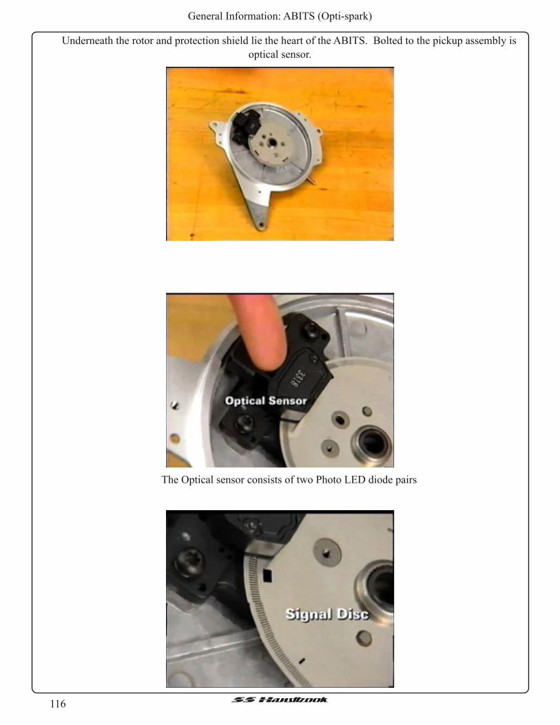
116SSHandbook
General Information: ABITS (Opti-spark)
Underneath the rotor and protection shield lie the heart of the ABITS. Bolted to the pickup assembly is
optical sensor.
The Optical sensor consists of two Photo LED diode pairs

117SSHandbook
General Information: ABITS (Opti-spark)
The Optical sensor is mounted so a two-track signal is between the LED and the Photo Diode
The Signal disc is connected to the distributor shaft and turns with the camshaft. The PCM sends two
5Volt reference signals to the optical sensor as the signal disc turns the two rows of slots on the signal disc
pass beteeen the LED photo diode pair this results in two pulsing signals. They are used to toggle the two 5V
reference signals that are sent from the PCM to ground or ZERO volts

118SSHandbook
General Information: ABITS (Opti-spark)
The outer ring of the signal disc contains 360 slots, which provide 720 tiny edges for the PCM. This is
known as the high resoultion signal.
The inner ring of the disc has 8 slots, each ofwhich have a leading edge 45 cam degrees away from the
next slot. These leading edges mark TDC for each cylinder.

119SSHandbook
General Information: ABITS (Opti-spark)
These leading edges mark TDC for each cylinder. The slots are different sizes, enabeling the PCM to
identify specific cylinders.
The PCM does this by counting the high resolution signal as the low resolution slots pass the optical
sensor. Different length low resolution slots allow the PCM to identify the different cylinders.

120SSHandbook
General Information: ABITS (Opti-spark)
Using inputs from the low resolution signal Including ECT, MAP, KSs and battery voltage the PCM
calculated coil dwell and spark advance.
From a low resolution signal going high the PCM starts counting high resolution signals to the beginning
of coil dwell and spark advance.

121SSHandbook
General Information: ABITS (Opti-spark)
The PCM then generates an electronic spark timing, for the ignition control outout, for the ignition control
driver module. The ignition control driver module turns on the primary current to the ignition coil when the
ignition control voltage goes approximately 4Volts. When the PCM counts enough high resolution edges to
reach the calculated spark advance it terminates the ignition control signal, and the ignition module turns off
primary voltage to the coil.
When the ignition control signal stops the primary current in the coil switches off inducing high voltage in
the coil’s secondary winding. The high voltage runs from the secondary of the coil to the rotor and is
distributed to the correct spark plug.
The ICM module doesn’t provide a backup mode (I.E. Min function or minimim function).

122SSHandbook
General Information: ABITS (Opti-spark)

123SSHandbook
General Information: ABITS (Opti-spark)
While the Ignition control module is smaller than an HE distributor module, it is still important when
installing a new module to coat both the heat sink and module base with thermal conductive grease. Thishelps the module disappate heat. Without the grease the module can over heat and that can lead to failure.

124SSHandbook
General Information: ABITS (Opti-spark)
The ABITS distributor cap intruduces secondary towers on the distributor cap conductive traces connect
to the spark plug by non radial paths using conductive ink. The ink traces are then encapsulated with epoxy.
This routing allows 4 plugs wires on each side without causing crossfire problems.
Proper ventilation is necessarry to prevent moisture buildup corrosive gasses formed by the high voltage
arc.
When ABITS was first introduced in 1992 it had ventilation holes drilled across the top.

125SSHandbook
General Information: ABITS (Opti-spark)
Ozone is heavier than air so it settles on the bottom of the distributor. And when it forms noitrogen and
moisture in the air it forms Nitric Acid. This can create conductive paths, and cause misfires and cross fires.
The corrosive problem was solved when the vent holes were moved to the bottom of the ABITS.

126SSHandbook
General Information: ABITS (Opti-spark)
The ventilation is further improved on the RoadMaster design with a forced ventilation system has a fresh
air system and a vacuum line.
The fresh air inlet runs from the distributor to the air inlet duct located just after the MAF sensor. By
plugging into the line just after the MAF the clean filtered air is accounted for by the PCM and doesn’t affect
fuel mixture.

127SSHandbook
General Information: ABITS (Opti-spark)
Just up from the orifice tube is a check valve. The blue side of the orifice tube faces the intake manifold.
Just up from the orifice tube is a check valve. The check valve does not allow air to reurn to the distriubutor.

128SSHandbook
General Information: ABITS (Opti-spark)
An inoperative ventilation line is a cause for misfire. If the fresh air inlet line becomes pinched or
plugged for any reason, it will draw vacuum on the distributor. As the vacuum is created inside the
distributor, the dielectric properties inside will go down, and as that happens, spark that would normally travel
from the center of the distributor cap find it much easier to go to the fastening screws on the rotor, which is a
goes to GND, causing a misfire. .

129SSHandbook
General Information: ABITS (Opti-spark)
Other problems may result if the air inlet line is plugged. In some cases engine vacuum is strong engough
to collaps the cap until it contacts the rotor. There’s enough vacuum to actually bend the distributor cap!

1 30SSHandbook
General Information: ABITS (Opti-spark)
Any tips on checking the ventilation system? Yes, but first let’s start the car.
1 . Unplug the air inlet of the distributor, and put your finger over it checking for a slight vacuum (Don’t
forget to plug the hole in the snorkel at this time).
Checking with a vacuum gauge (Mity-Vac or equivalent), Remove the air inlet from the snorkle and hook
a vacuum gauge up tho the inlet line. As engine runs the vacuum gauge should drop to very near intake
manifold vacuum..
Check for pinched vacuum hoses and also check for:
• Pinched or damaged hoses
• Pinched or plugged orifice
• Plugged check valve
• Poor distribution cap seal

1 31SSHandbook
General Information: ABITS (Opti-spark)
The harness is serviced as an assembly ONLY.
Upper ventilation is essential to good ABITS operation.
Fouled Plug vent systems may lead to:
• Fouled plugs & Misfires
A misfire may be caused by a ventilation system problem.
The causes ofNO spark & Intermittent complaints require addition diagnosis.
A Misfire may be caused by fouled plugs and plug wires
AMisfire may be caused by ventilation system problems. The causes ofNO spark or intermetent
complaints require additional diagnosis, Begin your system check with the ignition system check know how
technican’s manual.
The first step of this process is to check for trouble codes using the TECH-1 .
In addition to code 42, found on most ignition systems, ABITS has 16, 36 and 41 to aid in diagnostics of
problems

1 32SSHandbook
General Information: ABITS (Opti-spark)
Code 16 is Set
16= Low Resolution
• If 720 high resolution signals are seen by the PCM without a low resolution signal)
• (If the camshaft turns 1 complete revolution & the ABITS doesn’t provide high resolution signal for
piston location, a code 16 is set.
• The optical sensor diode for the high resolution signal must operate before a code 16 is set.
• A code 16 can be set by: an open, Shorted, or grounded low resolution wire (Open Terminal), failed
optical sensor, or a failed PCM.
• ENGINE WITH CODE 16 WILL NOT START

1 33SSHandbook
General Information: ABITS (Opti-spark)
Code 36 is set if• If PCM doesn’t get Hi-resolution signal for 9 consecutive low resolution signals.
1 . An open or shorted or grounded high resolution wire or open terminal.
2. A failed optical sensor diode.
3 . Failed PCM
A code doesn’t set when both optical diodes fail, but then the engine won’t start either.

1 34SSHandbook
General Information: ABITS (Opti-spark)

1 35SSHandbook
General Information: ABITS (Opti-spark)
Code 41 sets• In If an open exists in the ignition control circuit.
• The PCM looks for voltages above 4.5 volts on the ignition control line.
• When engine speed is below 1 ,500 RPM, a code 41 sets if there is an open in the ignition control line (or
if the ignition control line is shorted to voltage that is higher than 4.5 Volts)
Code 41 also sets if there is also an open terminal in the ignition control line.
• Code 41 sets if there is an open terminal.
• Failed PCM control driver module
• Ignition system check in tech manual (Shown above)
• Failed icon control driver module.
• Failed ICM control driver module
• Failed PCM (If voltage is less than 4 volts)

1 36SSHandbook
General Information: ABITS (Opti-spark)
A Code 42 is setIf the Ignition control line is grounded The PCM considers the control line grounded. (Less than if
voltge is less than 4 volts) A code 42 is most likely caused by a grounded ignition control wire. But it could
also be cause by a failed ignition driver module, or a failed PCM.
Code 41 & 42 are stored in Memory. If either are detcted the engine won’t start. The PCM disbles the
fuel injectors and don’t rurn on the MIL.
The ignition system checking chart becomes Invaluable.

1 37SSHandbook
General Information: ABITS (Opti-spark)
It provides an organized approach to engine diagosis
Check for voltage with an ST-125 (25K to fire this is an excellent test when checking for a misfire The
ignition system may be providing enough voltage to run the engine but not enough to fire the spark plugs
under heavy load). Resulting in a misfire. Since the ST-125 requiers 25,000 volts to fire it can be use used
the ignition system is producing enough voltage to fire. If the system isn’t producing adequate voltage Check
the voltage in the primary ignition cicruit
Disconnect the ignition coil driver module, and with the igniton ON check the voltage from terminals A
and D to Ground
If the coil is receiving adequate voltage both terminals should be receiving (10 volts or more)
Next connect the probes to Terminal ‘B’ (The ignition control line) and GND. And set the DVOM to the
A/C scale. Crank the engine, there should be between 1 and 4 volts.

1 38SSHandbook
General Information: ABITS (Opti-spark)
This check is the first in determining if the PCM is providing a signal to the ignition coil driver module.
If the PCM Isn’t providing a signal to the ignition coil driver module, the problem exists between the
distributor and the PCM.
If there wasn’t 1 -4 Volts the ignition system check examines more closely where the signal from the PCM
is breaking down.
Using the Tech-1 see if there is a low resolution signal. If there isn’t, turn the ignition off and disconnect
the distributor electrical connector.
• Turn the ignition Back on
• Probe terminal C with a test light (as shown)

1 39SSHandbook
General Information: ABITS (Opti-spark)
The light should illuminate, and if it doesn’t there isn’t any power going to the optical sensor.
The remaining test checks the various circuits individually. To see if the proper signals are being sent and
received from both the distributor and PCM.
If the light illuminated in the last test check for continuity between distributor connector D and Ground.
The circuit should have continuity.
Then using a DVOM on the DC scale
Measure voltage at distributor connector “A” (Checking the low resolution signal)
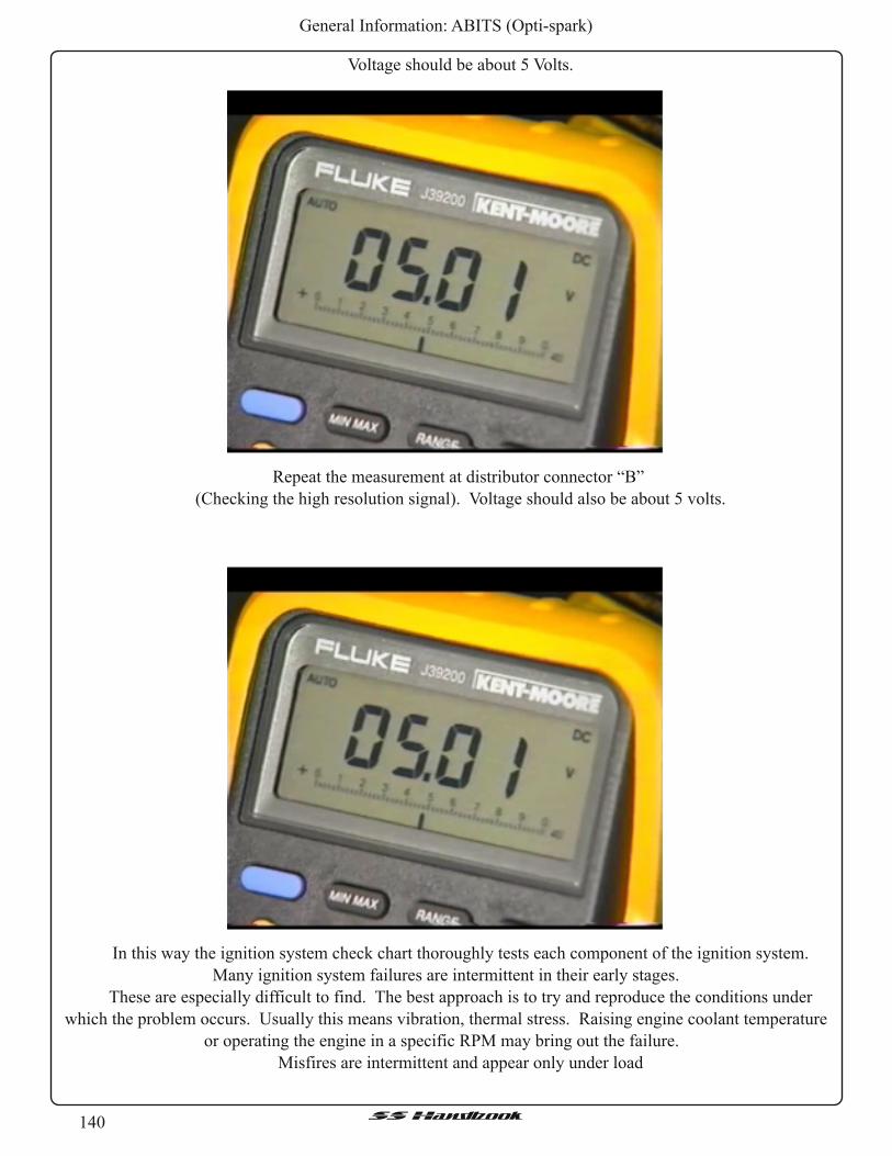
140SSHandbook
General Information: ABITS (Opti-spark)
Voltage should be about 5 Volts.
Repeat the measurement at distributor connector “B”
(Checking the high resolution signal). Voltage should also be about 5 volts.
In this way the ignition system check chart thoroughly tests each component of the ignition system.
Many ignition system failures are intermittent in their early stages.
These are especially difficult to find. The best approach is to try and reproduce the conditions under
which the problem occurs. Usually this means vibration, thermal stress. Raising engine coolant temperature
or operating the engine in a specific RPM may bring out the failure.
Misfires are intermittent and appear only under load

141SSHandbook
General Information: ABITS (Opti-spark)
Misfires are also due to a spark plug or secondary wire that is leaking voltage. If the engine misfires only
under a load, mist the wires with a vegetable sprayer. Spark escaping from the secondary circuit can usually
be seen under these conditions.

142SSHandbook
General Information: Part Numbers
Part Numbers
Here is a list of part numbers some may find useful while doing routine maintenance on their LT1 's.
REMEMBER, these numbers are for reference, so VERIFY them before placing an order.
2503679 1 BAR MAP SENSOR
12343958 12-DISC CD CHANGER ONLY USED WITH CASSETTE PLAYER.
12344015 12-DISC CD CHANGER HARNESS ONLY USED WITH CASSETTE PLAYER.
25008308 3.5" MAF SENSOR
12486041 350 HO CRATE MOTOR (330HP)
12495515 350 RAM JET MOTOR 350HP
12497323 502 RAM JET CRATE MOTOR 502HP
22094330 91 -96 B-BODYWINDSHIELD WIPERARM CAP
3535261 91 -96 B-BODYWIPERARM MOUNTING NUT
16188051 94-95 LT1 PCM
12552898 A.I.R. CHECK VALVE
22048212 A.I.R. PUMP CHECK VALVE 95-96
14100455 A.I.R. PUMP RELAY
12569122 A.I.R. SYSTEM DISABLE HOSE PLUG
12569123 A.I.R. SYSTEM DISABLE STICKER
52455732 A/C BLOWER MOTOR RESISTOR
12088567 A/C COMPRESSOR RELAY 95-96 ONLY
10115875 A/C DELETE PULLEY 1LE
52458911 A/C VAC CHECK VALVE A/C DASHBOARD
14056648 A/C VACUUM CHECK VALVE VACUUM HOSE ON ENGINE
12524176 ABS SENSOR O-RING REARAXLE
10242904 ACCELERATOR LINKAGE
11505169 ACCELERATOR LINKAGE BOLT
16757619 AIR BAG ASSEMBLY LIGHT GREY
10220594 AIR DEFLECTOR 9C1 - LEFT
10220593 AIR DEFLECTOR 9C1 - RIGHT
10188889 AIR DEFLECTOR BOLT FRONT AIR DAM - PK OF 10
10109530 AIR DEFLECTOR CENTER - 9C1 & SS
11514407 AIR DEFLECTOR NUT-CLAMP PACK OF 10
10161939 AIR DEFLECTOR SS - LEFT
10161938 AIR DEFLECTOR SS - RIGHT
25096932 AIR FILTER
25099478 AIR FILTER OUTLET DUCT PITCHER'S MOUND
25099945 AIR FILTER RESONATOR FRONT
25162682 AIR FILTER RESONATOR REAR
25147187 AIR INTAKE ELBOW 1LE - FOR VENTED OPTI
25147210 AIR INTAKE ELBOW 1LE - NO VENT FOR OPTI
25147186 AIR INTAKE ELBOWW/ATT 1LE
12344732 ALARM - VSS-150
12102668 ANTENNA CONNECTOR
10197140 ASHTRAY
12176639 AUX BATTERY POST
26018943 AXLE - 3.08 RELUCTOR B-BODY

143SSHandbook
General Information: Part Numbers
26018944 AXLE - 3.23 RELUCTOR B-BODY
26029418 AXLE - 3.42 GEARS FACTORY RING & PINION
26033578 AXLE - 3.42 GEARS PINION SEAL
26018945 AXLE - 3.42 RELUCTOR B-BODY
26018946 AXLE - 3.73 RELUCTOR B-BODY
26014585 AXLE - 4.1 0 GEARS MOTIVE GM MOT-
26016309 AXLE - 4.1 0 GEARS RING & PINION
9420095 AXLE - CARRIER SIDE BEARINGS 3.42 GEARS
26066456 AXLE - DIFFERENTIAL COVER GASKET 2ND DESIGN
55028-1 AXLE - DIFFERENTIAL COVER GASKET FELPRO RDS
1052271 AXLE - DIFFERENTIAL LUBE 80W/90
14056196 AXLE - DIFFERENTIAL RETAINER PIN PACK OF 10
14091497 AXLE - FACTORY RING & PINION
1052351 AXLE - GEAR MARKING COMPOUND
1052358 AXLE - LIMITED SLIP ADDITIVE
1234726 AXLE - PINION CRUSH COLLAR 3.42 GEARS
9418356 AXLE - PINION FRONT BEARING 3.42 GEARS
1260823 AXLE - PINION NUT
9413427 AXLE - PINION REAR BEARING 3.42 GEARS
26064028 AXLE - PINION SEAL (NEW STYLE) WON'T WORKW/STOCKYOKE
554631 AXLE - SEALS
12470387 AXLE - YOKE SERVICE KIT CONT. NEW PINION FLANGE
10128489 BALANCER/DAMPER - LT1 GM 92-97
125511 38 BALANCER/DAMPER 93-95
9440024 BALANCER/DAMPER BOLT
716910 BALANCER/DAMPER FLUIDAMPER 93-97
10168570 BALANCER/DAMPER HUB 93-95 B-BODY
12550097 BALANCER/DAMPER HUB 96
12550098 BALANCER/DAMPER HUB 96-97 LT1 & LT4
1981590 BATTERY SEO HEAVY DUTY
10109535 BATTERY TRAY
12550149 BELT
4040372 BELT 9C1 W/HD COOLING
4060642 BELT ACCESSORY
K060637 BELT GATES 21MM X 1635MM
12552509 BELT TENSIONER
457917 BODY BUSHING POSITION 7 - DK GREEN
457915 BODY BUSHINGS POSITION 1 ,2,3,4,6 - PINK
12361405 BOOST GAUGE 0-10PSI/0-30"2-5/8" W/BOWTIE
12361397 BOOST GAUGE 0-10PSI/0-30"2-5/8" W/GMPP
18021519 BRAKE - CALIPER BRACKETS 9C1 - CAD PLATED
18021945 BRAKE - CALIPER BRACKETS IMPALA - BLACK FINISH
18021517 BRAKE - CALIPER LH REAR
18021518 BRAKE - CALIPER RH REAR
18021516 BRAKE - EMERGENCY BRAKE KIT
18005606 BRAKE - FRONT CALIPER BUSHINGS ONE KIT PER CAR
18024928 BRAKE - FRONT PADS

144SSHandbook
General Information: Part Numbers
88917169 BRAKE - FRONT PADS (CERAMIC) AC 17 D614C
18039371 BRAKE - FRONT ROTOR (L) DURASTOP HP 18A1030
18039372 BRAKE - FRONT ROTOR (R) DURASTOP HP 18A1031
18027999 BRAKE - FRONT ROTOR DURASTOP #18A399
18021344 BRAKE - FRONT ROTOR IMPALA SS ACD 177-753
18021049 BRAKE - FRONT ROTOR NON-IMPALA SS ACD 177-754
18021515 BRAKE - PADS EMERGENCY BRAKE
10223533 BRAKE - PROPORTIONING VALVE
12337902 BRAKE - REAR BRACKET CALIPER BOLT
14067559 BRAKE - REAR CALIPER BOLT GUIDE PIN
14067552 BRAKE - REAR CALIPER BOOT GUIDE PIN
18022147 BRAKE - REAR CALIPER, GUIDE PIN
18021521 BRAKE - REAR PADS
18028256 BRAKE - REAR ROTOR DURASTOP #18A656
5976306 BRAKE - UPPER LAMPASSEMBLY
10225142 BUICK HARMONICS BRACE
10214403 BUMPER COVER FRONT
10214405 BUMPER COVER REAR
10214402 BUMPER COVER RETAINER
10249326 BUMPER MOLDING FRONT - BLACK
10267872 BUMPER MOLDING FRONT - DCM
10267871 BUMPER MOLDING FRONT - DGGM
10249329 BUMPER MOLDING REAR - BLACK LH
10249328 BUMPER MOLDING REAR - BLACK RH
10186281 BUMPER REINFORCEMENT FRONT
10161976 BUMPER REINFORCEMENT REAR
15989674 BUMPER, LOWER CONTROLARM, FROM S10 ZQ8 SUSPENSION PACKAGE.
10185071 CAMSHAFT CAMARO ZZ3 HO 350 CAM
10243779 CAMSHAFT LT1
12370406 CARPET / MATS BLACK MAT SET FRONT
12370411 CARPET / MATS BLACK MAT SET REAR
12343624 CARPET / MATS GRAY FRONT
12343594 CARPET / MATS GRAY REAR
12528553 CARPET / MATS GREY CARPET
10253509 CARPET / MATS RETAINER LF DOOR
10222523 CARPET / MATS RETAINER LR DOOR
10253508 CARPET / MATS RETAINER RF DOOR
10222524 CARPET / MATS RETAINER RR DOOR
10249851 CAT HEAT SHIELD (1 OF 2)
10222996 CAT HEAT SHIELD (2 OF 2)
10249851 10222996, CAT HEAT SHIELDS
12462981 CD CHANGER 12-DISC
11516141 CIGARETTE LIGHTER
11516142 CIGARETTE LIGHTERASSEMBLY SOCKET & LIGHTER
10248599 CIGARETTE LIGHTER BEZEL RIGHT SIDE OF RADIO
20038997 CLIP - RETAINERACC & CRUISE CABLES
12371180 CLOCK GAUGE 2-5/8" W/WHITE FACE/BOWTIE

145SSHandbook
General Information: Part Numbers
10260084 COIN HOLDER LEFT OF STEERING WHEEL
EAG-CRS5700B3D CONNECTING RODS - STROKER EAGLE 5.7" 650G
12495071 CONNECTING RODS GM STOCK 5.7" - SET OF 8
22555614 CONSOLE HINGE
12531192 CONSOLE LID
10282773 CONSOLE SHIFTERASSEMBLY
10271069 CONSOLE SHIFTER PLATE TOP COVER - 96
15956547 CONTROLARM - BUMP STOP NEW S10 ZQ8 DESIGN
88912477 CONTROLARM - BUMP STOP W/SELF LOCKING NUT
10282171 CONTROLARM - LOWER FRONT HEAVY DUTY 5/8" - LEFT
10282172 CONTROLARM - LOWER FRONT HEAVY DUTY 5/8" - RIGHT
10255857 CONTROLARM - REARAXLE NUT 9C1
18021377 CONTROLARM (HD) STEERING KNUCKLE LH - 5/8"
18021378 CONTROLARM (HD) STEERING KNUCKLE RH - 5/8"
11 508196 CONTROLARM BOLT 9C1 REARAXLE
10289786 CONTROLARMS REARAXLE KIT
10283878 COOLANT - DEXCOOL NOTICE STICKER
10285918 COOLANT - DEXCOOL RADIATOR CAP
10258505 COOLANT - FLOW CONT VALVE W/HOSES SEO GREEN - AC #15-5508
12135027 COOLANT - LEVEL SENS (8-WIRE)
12522853 COOLANT - RADIATOR HOSE KIT (?) SEO GREEN - 94 ONLY?
10197619 COOLANT - RADIATOR HOSE SEO LOWER
10260863 COOLANT - RADIATOR HOSE UPPER SEO GREEN
10246557 COOLANT - RADIATOR INSULATOR UPPER
12528777 COOLANT - RADIATOR OVERFLOW TANK
10219447 COOLANT - RADIATOR RECOVERY HOSE SEO GREEN
12522746 COOLANT - RADIATOR SUPPORT BRACE
12522867 COOLANT - RADIATOR TEE HEATERWATER BYPASS
10108635 COOLANT - STEAM PIPE ASSEMBLY 93-94-INCL SEALS & HOSE
12556260 COOLANT - STEAM PIPE CROSSOVER 95/96-INCL SEALS/HOSE/BOLTS
10108689 COOLANT - STEAM PIPE SEALS 93-96
12371176 COOLANT - TEMP GAUGE 140-250 2-5/8" W/WHITE FACE/BOWTIE
12361394 COOLANT - TEMP GAUGE140-240 2-5/8" W/GMPP ON FACE
12361402 COOLANT - TEMP GAUGE140-280 2-5/8" W/BOWTIE ON FACE
10096181 COOLANT - TEMP SENDING UNIT
25037332 COOLANT - TEMP SENSOR (GAUGE) AC #213-77
15326386 COOLANT - TEMP SENSOR (PCM) AC# 213-310 15326386 $ 10.95
12146312 COOLANT - TEMP SENSOR (PCM) NEW P/N 15326386
10157988 COOLANT FLOW CONTROL VALVE 8.866 (ALSO ACDELCO 15-5423)
10096163 COOLANT LEVEL SENSOR 2-WIRE 10096163 $ 23.35
12552974 COOLANT STEAM PIPE BOLTS 93-96 12552974 $ 3.07
12193604 COOLING FAN RELAY 94-96 - AC #15-8733
10208795 CORVETTE FUEL - RAIL COVER (LH)
10208794 CORVETTE FUEL - RAIL COVER (RH)
1022493692 CORVETTE FUEL - RAIL COVER (RH) STEEL VALVE COVERS
10214035 CORVETTE FUEL RAIL COVER HOSE BRAKE VACUUM BOOSTER
10476885 CRANK POSITION SENSOR SEAL 96 ONLY—OBD II

146SSHandbook
General Information: Part Numbers
10128365 CRANKCASE VENT HOSE 93-96 - FM V/C TO T/B
14088556 CRANKSHAFT - REAR MAIN SEAL HOUSING 93-96
12556307 CRANKSHAFT LT1 - OLD P/N 12551485
12555771 CRANKSHAFT REAR MAIN HSG GASKET 93-96
10088158 CRANKSHAFT REAR MAIN SEAL 93-96
12554314 CRANKSHAFT REAR MAIN SEAL REV GM LT4 DOUBLE LIP
10128316 CRANKSHAFT SEAL - FRONT 93-96
25140611 CRUISE CONTROL MODULE
10261527 CUP HOLDER CONSOLE INSERT
12561166 CYLINDER BLOCK LS6
585927 CYLINDER HEAD DOWEL PIN 93-97
12369145 CYLINDER HEAD GASKET KIT FORALUMINUM HEADS
12553160 CYLINDER HEAD GASKET LT1 IRON - .029" COMP
12480092 CYLINDER HEAD HP LT1 IRON
12556463 CYLINDER HEAD HP LT4 - HOT CAM
12560801 CYLINDER HEAD LS6
12529741 CYLINDER HEAD LT1
10207643 CYLINDER HEAD LT1 ALUMINUM
12363287 CYLINDER HEAD STOCK LT4-COMPLETE
11 -235-4103 CYLINDER HEAD STUDS ARP
10248200 DASH PAD (GRAY)
10268239 DASH PLATE CAPRICE SS
10250947 DASH PLATE IMPALA SS
24210915 DEEP TRANSMISSION PAN--NO DRAIN PLUG
12344998 DETAIL KIT IN A CASE WITH BOWTIE LOGO
12346290 DEXCOOL GALLONS
10474278 DISTRIBUTOR DRIVE SHAFT SEAL
16671511 DOOR COURTESY LAMP
16627914 DOOR HANDLE BLACK
10273578 DOOR HANDLE PRIMED
166300597 DOOR LOCK MODULE 6N1 - POLICE
10190343 DOOR PANEL - OUTER SHELL LR
10190342 DOOR PANEL - OUTER SHELL RR
10250953 DOOR PANEL INNER SHELL LH
10250952 DOOR PANEL INNER SHELL RH
12521582 DOOR PANEL OUTER SHELL LF
12521583 DOOR PANEL OUTER SHELL RF
15600382 DOOR PANEL RETAINERS (20)
16671421 DOOR PULL BLACK
10111989 DOOR SILL PLATE FRONT DRIVERS
10031004 DOOR SWICTH LAMP BLUE PONTIAC
16671169 DOOR TRIM - WOOD GRAIN BEZEL
20669667 DRIVING LIGHT LAMPASSY SWITCH
10054880 EGR - BLOCK-OFF PLATE
10055726 EGR - PIPE GASK 94-96
1997223 EGR - SOLENOID VALVE
17113382 EGR - VALVE B-BODY

147SSHandbook
General Information: Part Numbers
1711 3381 EGR - VALVE F-BODY
12337972 EGR & EGR BLOCK-OFF PLATE GASKET AC #219-21
12129481 ELECTRICAL RECALL PARTS BUSBAR CAVITY
12146182 ELECTRICAL RECALL PARTS BUSBARCAVITY
12146183 ELECTRICAL RECALL PARTS CENTER STUD
11516161 ELECTRICAL RECALL PARTS NUT&STUD ASSEMBLY
121611 30 ELECTRICAL RECALL PARTS STUD ASSEMBLY
12344614 ELECTROCHROMIC MIRRORWITH COMPASS
10424491 EMBLEM - C PILLAR LEFT - OLD P/N 10253595
10253594 EMBLEM - C PILLAR NEW P/N 10424490
10253595 EMBLEM - C PILLAR NEW P/N 10424491
10424490 EMBLEM - C PILLAR RIGHT - OLD P/N 10253594
11516061 EVAP - BRACKET BOLT
10229207 EVAP - BRACKET FUEL TANK EVAP - CONT
17113065 EVAP - CANISTER
12553048 EVAP - CANISTER BRACKET
12551177 EVAP - CANISTER BRACKET BOLT
11514596 EVAP - CANISTER BRACKET NUT
10009923 EVAP - CANISTER BRACKET RETAINER PACK OF 10
11509509 EVAP - CANISTER BRACKET SCREW PACK OF 10
12124134 EVAP - CANISTER CHECK VALVE VACUUM
1997201 EVAP - CANISTER PURGE SOLENOID
12555984 EVAP - CANISTER PURGE SWITCH
9438315 EVAP - HOSE
10105324 EVAP - SOLENOID HOSE FROM THROTTLE BODY
12551376 EXHAUST - EXPORT EMISSIONS STICKER - 94
10243955 EXHAUST - EXPORT EMISSIONS STICKER - 95
12553939 EXHAUST - EXPORT EMISSIONS STICKER - 96
10168551 EXHAUST - EXPORT PIPE GASKET
10204015 EXHAUST - EXPORT PIPE LH
10204014 EXHAUST - EXPORT PIPE RH
10220453 EXHAUST - EXPORT PIPE STUD 10 PER PACK
12552469 EXHAUST - MANIFOLD GASKET 93-96
FEL-1406 EXHAUST - MANIFOLD GASKET FELPRO - BIG "D"-PORT
FEL-1405 EXHAUST - MANIFOLD GASKET FELPRO - BIG SQUARE
FEL-1404 EXHAUST - MANIFOLD GASKET FELPRO - REG SQUARE
10168494 EXHAUST - MANIFOLD LH
12552896 EXHAUST - MANIFOLD LH
12524289 EXHAUST - MANIFOLD RH
12556731 EXHAUST - MANIFOLD RH
10243316 EXHAUST - SYSTEM INSULATOR LARGE
10217783 EXHAUST - SYSTEM INSULATOR SMALL
GMP96B FACTORY SERVICE MANUALS 2-VOLUME SET
12193601 FAN - BLOWER MOTOR RELAY
30531901 FAN - THERMOSTATIC SWITCH
10281083 FAN SHROUD
12501861 FENDER LEFT FRONT

148SSHandbook
General Information: Part Numbers
12522388 FENDER LINER LEFT FRONT
12522387 FENDER LINER RIGHT FRONT
12501860 FENDER RIGHT FRONT
14088765 FLYWHEEL
25121978 FUEL - FILTER
25121293 FUEL - FILTERAC #GF578
17124248 FUEL - INJECTOR 93-96
1711 3544 FUEL - INJECTOR O-RING SEAL KIT AC #217-1 379
12048089 FUEL - LINE RETAINERS ON SIDE OF T/B
12371178 FUEL - PPRESS GAUGE 0-15 2-5/8" W/BOWTIE
10216948 FUEL - PRESS REG VACUUM HOSE
12361404 FUEL - PSI GAUGE 0-15 2-5/8" W/BOWTIE
12361396 FUEL - PSI GAUGE 0-15 2-5/8" W/GMPP
12361398 FUEL - PSI GAUGE TUBING KIT BRADED S/S
EP381 FUEL - PUMP HIGH OUTPUT ACDELCO
12077866 FUEL - PUMP RELAY 94-96 - AC #15-5671
EP376 FUEL - PUMP STOCKACDELCO
17113251 FUEL - RAIL 94-96 RH
10224936 FUEL - RAIL COVER CORVETT - RH SIDE
10108672 FUEL - RAIL COVER STUD VETT
17113095 FUEL - RAIL KIT PARTS FOR RETURN LINE
101911 38 FUEL - TANK HEAT SHEILD (1 OF 2)
10203814 FUEL - TANK HEAT SHEILD (2 OF 2)
25028955 FUEL - TANK LEVEL SENDING UNIT
NAPA 888536 FUEL PUMP HARNESS FOR IN-TANK SENDING UNIT
ACDELCO EP381 FUEL PUMP HIGHER OUTPUT VERSION
ACDELCO EP376 FUEL PUMP OE REPLACEMENT
101911 38 10203814, FUEL TANK HEAT SHIELDS
12527729 GLOVE BOX LATCH
3848911 GM "WHITE" OIL PUMP SPRING
10269614 GRILLE BLACK
10249082 GRILLE BOWTIE CHROME
10269616 GRILLE DCM
10269615 GRILLE DGGM
22591876 GRILLE EMBLEM BLUE BOWTIE
15970086 GRILLE EMBLEM RED "SS"
22591877 GRILLE EMBLEM RED BOWTIE
FEL-1074 HEAD GASKETS (LT1 ALUMINUM HEADS) FELPRO, .039"
10168457 HEAD GASKETS (LT4 ALUMINUM HEADS), .043"
16519235 HEADLIGHT - CAPSULE LEFT
16519236 HEADLIGHT - CAPSULE RIGHT
6288471 HEADLIGHT - CONNECTOR EXPORT T84 CAPSULE
16519237 HEADLIGHT - EXPORT T84 CAPSULE LEFT
16519238 HEADLIGHT - EXPORT T84 CAPSULE RIGHT
16511961 HEADLIGHT - MOUNTING BRACKET LEFT
16511962 HEADLIGHT - MOUNTING BRACKET RIGHT
10161999 HEADLIGHT - OPENING FILLER LEFT

149SSHandbook
General Information: Part Numbers
10161998 HEADLIGHT - OPENING FILLER RIGHT
6294068 HEADLIGHT - TERMINAL EXPORT T84 CAPSULE
10279131 HEADLINER
52469251 HEATER CORE
10256544 HEATER CORE HOSE IN/OUT ASSEMBLY SEO GREEN
10164972 HEATER DISTRIBUTOR REAR FLOOR DUCTS
10164975 HEATER OUTLET LH REAR FLOOR DUCTS
10164974 HEATER OUTLET RH REAR FLOOR DUCTS
20030401 HEATER RETAINER REAR DUCT
10248301 HOOD
10109664 HOOD HINGE
10109665 HOOD HINGE
10196123 HOOD INSULATION
20064875 HOOD INSULATOR RETAINER
10203566 HOOD LAMP - DISCONTINUED
15306195 HOOD LAMP CONNECTOR
10186229 HOOD LATCH RELEASE CABLE
1892246 HORN CADILLAC HORN C NOTE
1892162 HORN CADILLAC HORN D NOTE
10128361 HOSE CLAMP VETT PLASTIC VLV COVER
12553250 HUB, BALANCER/DAMPER 93-95 ?
5234890 HYDRAULIC LIFTER 93-95
17120735 HYDRAULIC LIFTER 96
12371042 HYDRAULIC LIFTER KIT
24501365 HYDRAULIC LIFTER, BOLTS
12550002 HYDRAULIC LIFTER, GUIDES
14101116 HYDRAULIC LIFTER, RETAINER
120386 HYDRAULIC LIFTER, WASHERS
CCA-850-16 HYDRAULIC LIFTERS CC HIGH ENERGY
10477208 IGNITION - COIL - 94-95 AC #D573
10489421 IGNITION - COIL - 96 AC #D577
12096466 IGNITION - COIL - WIRE - 93-95 AC PART # 340R
12173578 IGNITION - COIL - WIRE - 96 AC PART # 346U
1115315 IGNITION - COIL 93/AC #D535
10483131 IGNITION - CONTROL MODULE - 93 AC #D1971A
10483139 IGNITION - CONTROL MODULE - 94-95 AC #D1986A
10482803 IGNITION - CONTROL MODULE - 96 AC #579
16164576 INSTRUMENT CLUSTER LENS
10250238 INSTRUMENT CLUSTER TRIM BEZEL
12160244 INTAKE - AIR TEMP (IAT) SENSOR
20-25147187 INTAKE BELLOWS THUNDER RACING
FEL-1284 INTAKE GASKETS FELPRO
12367777 INTAKE MANIFOLD GASKET GM LT4 - RAISED PORTS
12524653 INTAKE MANIFOLD GASKET SET LT1
12552137 INTAKE MANIFOLD LT1
10231273 JACK
10239647 KEYLESS ENTRY FOB

1 50SSHandbook
General Information: Part Numbers
12499735 KEYLESS ENTRY RECEIVER
15725423 KEYLESS ENTRY TRANSMITTER 94-95
16245100 KEYLESS ENTRY TRANSMITTER 96-02
16214671 KNOCK MODULE - LT1 CORVETTE
16217700 KNOCK MODULE - LT1 F-BODY OBD-I
16214661 KNOCK MODULE - LT1 F-BODY OBD-II
16214681 KNOCK MODULE - LT4 CORVETTE
16188309 KNOCK MODULE 94/95 SS
16214691 KNOCK MODULE 96 SS
10456126 KNOCK SENSOR - LT1 94-95 - AC #213-96
10456287 KNOCK SENSOR - LT1 96 - AC #213-325
88890544 LS1 ENGINE 00 VETT
89017548 LS1 ENGINE 01 -04 VETT
12455109 LS1 ENGINE 97-98 VETT
88894086 LS1 ENGINE 98 F-CAR
88894386 LS1 ENGINE 98 F-CAR
88890543 LS1 ENGINE 99 VETT
88890545 LS1 ENGINE 99-00 F-CAR
25534322 LS1 ENGINE CRATE MOTOR-320HP
89017654 LS2 ENGINE - LONGBLOCK 05 VETT
88894384 LS6 ENGINE 01 VETT
89017349 LS6 ENGINE 03-04 VETT
89017653 LS6 ENGINE 05 CADDY
88894193 LT1 ENGINE - 94-95 B-BODY
88894195 LT1 ENGINE - 95 F-FODY
88894194 LT1 ENGINE - 96 B-BODY
88894197 LT1 ENGINE - 96-97 F-FODY
12527740 LT1 WATER PUMP B BODY
12527741 LT1 WATER PUMP F, Y BODY
12370835 LT1 /LT4 EXTREME DUTY ROLLER TIMING SET
12555885 LT1 /LT4 ROLLER TIMING SET CAM GEAR (95+ LT1 ) OR 94 + B-BODY
12555886 LT1 /LT4 ROLLER TIMING SET CRANK GEAR (95+ LT1 ) OR 94 + B-BODY
12555887 LT1 /LT4 ROLLER TIMING SET ROLLER CHAIN (95+ LT1 ) OR 94 + B-BODY
10260166 LT4 - ACCELERATOR LINKAGE COVER
12551486 LT4 - BALANCER/DAMPER F&Y-BODY LT4 ONLY
24502586 LT4 - CAMSHAFT HOT CAM
12480002 LT4 - CAMSHAFT HOT CAM KIT
12557236 LT4 - CYLINDER HEAD GASKET LT4 - .051 " COMP THICK
12551488 LT4 - CYLINDER HEAD GASKET STOCK LT4 - .050" COMP
12552126 LT4 - CYLINDER HEAD STUD LT4
12551183 LT4 - ENGINE (DISCONTINUED) NEW P/N 88894198
1255131 3 LT4 - EXHAUST VALVE
12495499 LT4 - HEAD BOLT KIT
12555331 LT4 - INTAKE VALVE
12338092 LT4 - VALVE COVER BOLT LT4 PLASTIC COVER
14094717 LT4 - VALVE COVERWASHER
12495503 LT4 - VALVE LOCK SET OF 32

1 51SSHandbook
General Information: Part Numbers
12495492 LT4 - VALVE RETAINER SET OF 16
12551483 LT4 - VALVE SPRING
12495494 LT4 - VALVE SPRING MAX .525" LIFT - SET OF 16
24503856 LT4 - VALVE STEM KEY PACK OF 10
12337955 LUG NUTS SET OF 5
12529241 MAF SENSOR - EXTENSION CABLE
16137039 MAP SENSOR NEW P/N 12569240
1635948 MAP SENSOR SEAL 94-96
12047767 METRI-PAK TERMINALS (10PK)
12371585 MIRROR - INSIDE REARVIEWWITH COMPASS
10231161 MIRROR LH OUTSIDE 93/94
10231121 MIRROR LH OUTSIDE 95/96
10231160 MIRROR RH OUTSIDE 93/94
10231120 MIRROR RH OUTSIDE 95/96
10263981 MIRROR, INSIDE AUTO DIM W/MAP LIGHTS
12482046 MOLDING - REAR SIDE
12522934 MOLDING - REAR SIDE
12522935 MOLDING - REAR SIDE
12522931 MOLDING - WHEELWELL FRONT BLACK LH
12522930 MOLDING - WHEELWELL FRONT BLACK RH
12524189 MOLDING - WHEELWELL FRONT DCM LH
12524188 MOLDING - WHEELWELL FRONT DCM RH
12524187 MOLDING - WHEELWELL FRONT DGGM LH
12524186 MOLDING - WHEELWELL FRONT DGGM RH
12522937 MOLDING - WHEELWELL REAR BLACK LH
12522936 MOLDING - WHEELWELL REAR BLACK RH
12524197 MOLDING - WHEELWELL REAR DCM LH
12524196 MOLDING - WHEELWELL REAR DCM RH
12524195 MOLDING - WHEELWELL REAR DGGM LH
12524194 MOLDING - WHEELWELL REAR DGGM RH
12516867 MOLDING KIT FRT S/D LWR (LEFT)
12482045 MOLDING REAR SIDE
22146273 MOTOR MOUNT LT1 -LEFT
22146274 MOTOR MOUNT LT1 -RIGHT
10279898 MUFFLER HEAT SHIELD (1 0F 2)
10279899 MUFFLER HEAT SHIELD (2 0F 2)
10279898 10279899, MUFFLER HEAT SHIELDS
12343477 NET CARGO PACKAGE
15966491 NUT CLIP SHEET METAL
10226222 OIL - COOLER 9C1 AIR-TO-OIL COOLER
10260341 OIL - COOLER HOSE ASSEMBLY 9C1 AIR-TO-OIL COOLER
12337917 OIL - COOLER NUT
10225895 OIL - COOLER PIPE 9C1 AIR-TO-OIL COOLER
10225896 OIL - COOLER PIPE 9C1 AIR-TO-OIL COOLER
20351035 OIL - COOLER SCREW
14090908 OIL - COOLER TUBE SEAL 2 REQUIRED
23011420 OIL - DRAIN PLUG GM MAGNETIC PLUG

1 52SSHandbook
General Information: Part Numbers
12554955 OIL - FILL CAP LT4 - MOBIL 1
10229162 OIL - FILL CAP STEEL VALVE COVERS
12558300 OIL - FILL CAP VALVE COVER MAGNESIUM
10108694 OIL - FILL CAP VETT PLASTIC VALVE COVER
10236268 OIL - FILL STICKER LT4 - MOBIL 1
25322836 OIL - FILTERAC #PF52 - ULTRAGUARD GOLD
12551589 OIL - FILTERADAPTER GASKET
88893990 OIL - FILTERADAPTER KIT INCLUDES GASKET & O-RINGS
10244495 OIL - FILTERADAPTER O-RING
24507190 OIL - LEVEL SENSOR (LOW)
10108676 OIL - PAN GASKET
14088501 OIL - PAN RAIL LH
14088502 OIL - PAN RAIL RH
12554816 OIL - PAN WINDAGE TRAY GM
12371175 OIL - PSI GAUGE 0-100 PSI 2-1 /1 6" WHITE FACE/BOWTIE
12361400 OIL - PSI GAUGE 0-100 PSI 2-5/8" W/BOWTIE ON FACE
12361392 OIL - PSI GAUGE 0-100 PSI 2-5/8" W/GMPP ON FACE
10201491 OIL - PSI SENDER SEO POLICE
10137636 OIL - PSI SENSOR 90 FITTING
12555884 OIL - PUMPW/O PICK-UP
12361401 OIL - TEMP GAUGE 140-280 2-5/8" W/BOWTIE ON FACE
12361393 OIL - TEMP GAUGE 140-280 2-5/8" W/GMPP ON FACE
10096181 OIL - TEMP SENDING UNIT
12102748 OIL - TEMP SENDSOR CONNECTOR
25325403 OIL FILTERAC PF52(DURAGUARD SILVER)
25171377 OIL FILTERAC PF52(DURAGUARD)
134-7901 OIL PUMP DRIVESHAFT, ARP
IS-55E OIL PUMP DRIVESHAFT, MELLING
12106559 OPTI-SPARK - ELECT HARNESS 93-94 - NON-VENTED
12130319 OPTI-SPARK - ELECTRICAL HARNESS 95-96 - VENTED
14082470 OPTI-SPARK - FITTING GM VAC
10457702 OPTI-SPARK - NON-VENTED 93-94
10128317 OPTI-SPARK - SHAFT SEAL 93-94
12552428 OPTI-SPARK - SHAFT SEAL 95-96
12555323 OPTI-SPARK - VENT & VAC HARNESS 95-1997
1104032 OPTI-SPARK - VENTED 95-1997
10457293 OPTI-SPARK CAP & ROTOR KIT (INC BOLTS/COVER/O-RINGS) - AC #D8301
25312184 OXYGEN SENSORAC #AFS75
88961150 PCM 94-95 SS
16214399 PCM 96 SS
9416200341 PCM CALIBRATION - 94 INITIAL
9416232021 PCM CALIBRATION - 94 UPDATE FIX FOR CHUGGLE AND SURGE
9416207221 PCM CALIBRATION - 94 UPDATE FIX SHIFT CLUNK/COLD SURGE
9416202491 PCM CALIBRATION - 94 UPDATE IMPROVE AIR PERFORMANCE
9516206641 PCM CALIBRATION - 95 INITIAL
9516232011 PCM CALIBRATION - 95 UPDATE CORRECT CHUGGLE & SURGE
9516209351 PCM CALIBRATION - 95 UPDATE IMPROVE DRIVEABILITY

1 53SSHandbook
General Information: Part Numbers
9616229981 PCM CALIBRATION - 96 INITIAL
12084913 PCM CONNECTORS (5PK)
10240678 PCV GROMMET - INTAKE MANIFOLD VETT PLASTIC VALVE COVER
12556257 PCV PIPE
25095452 PCV VALVE 93-96/AC #CV895C
12551389 PCV VALVE ELBOW
R-9401 35 PISTON RING SPEEDPRO 4.030
139628 PISTON SRP-4.030, 1 6CC, 5.7" ROD
24213991 PLUG--HEX HEAD, FOR DEEP PAN PLUG
8891017 POWERANTENNA
22535475 POWERANTENNARELAY
10099012 POWER SEAT SWITCH 6-WAY
26055706 POWER STEERING NEW PUMP FOR 94-96 CHEVY B W/N40 STEERING
88985220 POWER STEERING REMAN PUMPACDELCO 36-516309
10188907 POWERWINDOW SWITCH REAR
17113086 PRESSURE REGULATOR SEAL KIT
12371041 PUSHROD KIT CONTAINS 16
CC-7940-16 PUSHRODS CC HARDENED
10041121 RACKS & CARRIERS
15757172 RADIO CASSETTE PLAYER
15071233 RADIO CD PLAYER
12555714 REAR MAIN SEAL HOUSING GASKET
1052369 REARVIEWMIRRORADHESIVE
CCA-1305-16 ROCKERARMS CC PRO MAG 1 .6 W/ 7/16" STUD
12495490 ROCKERARMS STAMPED STEEL 1 .5
12370839 ROLLER ROCKERS 1 .6 RATIO GM SPEC CRANE R/R
16726726 SEAT
16731968 SEAT
12513339 SEAT BELT KIT FRONT LH
12513338 SEAT BELT KIT FRONT RH
16780068 SEAT COVER FRONT LOWER CUSHION
22003254 SHOCK - AIR
22064600 SHOCKABSORBERS FRONT
22064499 SHOCKABSORBERS REAR
10267037 SIDE SCRIPT CAPRICE SS - BLACK
10267039 SIDE SCRIPT CAPRICE SS - DCM
10267038 SIDE SCRIPT CAPRICE SS - DGGM
10248742 SIDE SCRIPT IMPALA SS BLACK
10262809 SIDE SCRIPT IMPALA SS DCM
10262808 SIDE SCRIPT IMPALA SS DGGM
25166821 SPARK PLUG
12096437 SPARK PLUG WIRE SET
12173568 SPARK PLUG WIRE SET
12524697 SPOILER
12337977 SPOILER - BOLTS
22076523 SPRINGS 1994-96 7B3 SUSPENSION - 9C1
22076517 SPRINGS 1995 REAR - 18.0 N/MM RC

1 54SSHandbook
General Information: Part Numbers
22076526 SPRINGS 1995 REAR - 27.0 N/MM RX
22132375 SPRINGS 1995 REAR - STOCK
22078017 SPRINGS HIGHEST LOAD RATE-95 FRONT
10465143 STARTER
10465293 STARTER
10455709 STARTER--GEAR REDUCTION, LIGHTWEIGHT, FROM 92-96 LT1 CORVETTE
26001594 STEERING - CONNECTION SEAL PACK OF 10
11509363 STEERING - COOLER BOLT
2091638 STEERING - COOLER CLAMP
11518121 STEERING - COOLER NUT
26036034 STEERING - COOLER PIPE
454947 STEERING - DAMPER BOLT
10245794 STEERING - DAMPER BRACKET
4993536 STEERING - DAMPER BUICK STYLE
9442937 STEERING - DAMPER NUT SOLD IN PACK OF 10
26059109 STEERING - DAMPER ROD KIT
1050017 STEERING - FLUID SOLD IN PACK OF 12
26048653 STEERING - GEAR BOX
88911336 STEERING - IDLERARM (DANA-SPICER) W/BONDED BLUE POLY SEALS
26041013 STEERING - IDLERARM (STOCK)
6055706 STEERING - PUMP (NEW STYLE) 94-96 W/N40 STEERING 2
36-516309 STEERING - PUMP (REMAN) AC
26014085 STEERING - SHAFT ASSEMBLY
10225365 STEERING - STOP LARGER THAN STOCK - LH
10225366 STEERING - STOP LARGER THAN STOCK - RH
16757633 STEERING - WHEEL GREYW/AIR BAG
MOR-86015 SWAYBAR - (HA) FRONT
MOR-86516 SWAYBAR - (HA) REAR
26039956 SWAYBAR - BUSHINGS 32MM FOR HA SWAYBAR
14094388 SWAYBAR - BUSHINGS 34MM FOR HA SWAYBAR
10221779 SWAYBAR – END LINKS F-BODY STYLE
457923 SWAYBAR – FRONT
88912162 SWAYBAR - FRONT END LINK KIT
88912214 SWAYBAR - LINK KIT SIMILAR TO P/N 10221779
10207649 SWAYBAR - REAR
10225157 SWITCH - SEO 6H6 RH 1 -BUTTON/LIGHTS OFF
10225158 SWITCH - SEO 6H6 RH 2-BUTTON SWITCH
10188966 SWITCH - SEO 6H6 RH SEO 6H6 1 -BUTTON/TRUNK
10203772 SWITCH - WAGON RIGHT SIDE OF RADIO
5977447 TAILLIGHT - ASSEMBLY LEFT - COMPLETE
5977448 TAILLIGHT - ASSEMBLY RIGHT - COMPLETE
16521719 TAILLIGHT - LENS ONLY CAPRICE - LEFT
16521720 TAILLIGHT - LENS ONLY CAPRICE - RIGHT
16522451 TAILLIGHT - LENS ONLY SS - LEFT
16522452 TAILLIGHT - LENS ONLY SS - RIGHT
12555290 THERMOSTAT
12553106 THERMOSTAT HOUSING GASKET

1 55SSHandbook
General Information: Part Numbers
10105379 THROTTLE BODY - GASKET 48MM
17113178 THROTTLE BODY - GASKET KIT COMPLETE
17113074 THROTTLE BODY - GASKETS TOP & BOT - AC #40-743
1711 3099 THROTTLE BODY - IAC VALVE 94-95 - AC #217-429
1711 3188 THROTTLE BODY - IAC VALVE 96 - AC #217-433
17106682 THROTTLE BODY - TPS SENSOR 93 W/SCREWS
17106680 THROTTLE BODY - TPS SENSOR 94-96 W/SCREWS
112-504 THROTTLE BODY HOLLEY 58MM
10128349 TIMING CHAIN - CAM GEAR 94-96 LT1
10206039 TIMING CHAIN - CAM SPROCKET 95-96
12551636 TIMING CHAIN - COVER 93-94 - INCL ROUND SEALS
12552426 TIMING CHAIN - COVER 95 - INCL ROUND SEALS
12552427 TIMING CHAIN - COVER 96 - INCL ROUND SEALS
12554553 TIMING CHAIN - COVER DOWEL PIN 93-97
10128293 TIMING CHAIN - COVER GASKET 93-96
10128346 TIMING CHAIN - CRANK GEAR 94-96 LT1
10128303 TIMING CHAIN - CRANK SPROCKET KEY 92-95 ENGINES ONLY
10128485 TIMING CHAIN 93-96
TCS45956 TIMING CHAIN FELPRO
10269710 TRANS - COOLER PIPE AIR-TO-TRANS HOSE ASSY
10269707 TRANS - COOLER PIPE RADIATOR-TO-COOLER
8679994 TRANS - DEEP PAN
4215535 TRANS - DEEP PAN - TRUCK STYLE MUST USE FILTER KIT 24208576 2
8633208 TRANS - DEEP PAN FILTER BOLT
24208576 TRANS - DEEP PAN FILTER KIT INCLUDES SEAL & GASKET
8629523 TRANS - DEEP PAN FILTER SPACER
24209295 TRANS - DEEP PAN NO DRAIN PLUG
8629526 TRANS - DEEP PAN OIL - INTAKE PIPE
12338119 TRANS - DOWL PIN REAR OF BLOCK
12337210 TRANS - FILTER KIT EXTRA DEP PAN
24200796 TRANS - FILTER KIT INCL SEAL & GASKET
24215535 TRANS - PAN PLUG HEX HEAD,
8667545 TRANS - PAN STOCK
24201203 TRANS - TORQUE CONVERTER 86 VETT
24202310 TRANS - TORQUE CONVERTER 95 S10-140K FACTOR
24204670 TRANS - TORQUE CONVERTER 96 S10-1 35K FACTOR
1261968 TRANS - TORQUE CONVERTER BOLT 85/86 VETT
12497318 TRANSMISSION 4L60E GMPP TAHOE MOD/370LB-FT
12523079 TRUNK EMBLEM BLACK
12524203 TRUNK EMBLEM DCM
12524202 TRUNK EMBLEM DGGM
10268235 TRUNK LAMPASSEMBLY 2ND DESIGN LATE 95
10211580 TRUNK MAT SEO B48 - B42?
5976555 TURN SIGNAL LEFT FRONT
5976557 TURN SIGNAL LEFT FRONT
25140743 TURN SIGNAL LEVERW/CRUISE CONTROL
5976556 TURN SIGNAL RIGHT FRONT

1 56SSHandbook
General Information: Part Numbers
5976558 TURN SIGNAL RIGHT FRONT
10220597 USE OVERDRIVE DURING… STICKER
12564852 VALVE - EXHAUST SEAL LT4
10212810 VALVE - INTAKE SEAL LT4
460483 VALVE - OIL SEAL LT1 INTAKE & EXHAUST
10212808 VALVE - SPRING CAP LT4
10212809 VALVE - SPRING SHIM LT4 - PACK OF 10
274288 VALVE - STEM TIRE - SOLD IN SETS OF 5
14088793 VALVE COVER - BOLT GASKETS BAG OF 10 - MAGNESIUM V/C
12356818 VALVE COVER - BOLTS - CHROME
10088165 VALVE COVER - BOLTS MAGNESIUM V/C
12355350 VALVE COVER - CHROME W/RED BOWTIE - SET
12552321 VALVE COVER – CORVETTE
12552322 VALVE COVER - CORVETTE
14088564 VALVE COVER - GASKET NEOPRENE - MAGNESIUM V/C
10108625 VALVE COVER - GASKET VETT PLASTIC
10046089 VALVE COVER - GASKETS IRON CYLINDER HEAD
10055781 VALVE COVER - MAGNESIUM LH
10055782 VALVE COVER - MAGNESIUM RH
10108675 VALVE COVER - NUT (PACK OF 10) FOR COMPOSITE V/C
10108674 VALVE COVER - STUD FOR COMPOSITE V/C
15552872 VEHICLE SPEED SENS (VSS) O-RING AUTO TRANS
12361406 VOLT GAUGE 8-18 VOLTS 2-5/8" W/BOWTIE ON FACE
123701176 VOLT GAUGE 8-18 VOLTS 2-5/8" W/WHITE FACE/BOWTIE
10261164 WARRANTY & OWNER'S BOOKLET
10128487 WATER PUMP - DOWEL PIN 93-96
12553792 WATER PUMP - DRIVE O-RING 93-96
10219554 WATER PUMP - DRIVE SHAFT 93-96
10128343 WATER PUMP - GASKET 93-96
10217886 WATER PUMP - SHAFT SEAL TIMING CHAIN COVER
12360496 WHEEL - 17" X 8.5" EACH
12495438 WHEEL - 17X8.5 (SET OF 4) EST $125 SHIPPING
15988450 WHEEL - HUB CAP RED BOWTIE
9592426 WHEEL - HUB CAPS BLACK BOWTIE
9592229 WHEEL - HUB CAPS STOCK IMPALA
9591766 WHEEL - SPARE TIRE WHEEL 16X4 - DOESN'T INCLUDE TIRE
16631405 WINDOW - REGULATOR MOTOR?
9442468 WINDOW ROLLER FIX RIVETS PACK OF 5
9666748 WINDOW ROLLERS PACK OF 5
22144138 WINDSHIELD WASHER CONTAINER
22127653 WINDSHIELD WASHER PUMP 96
10283602 WINDSHIELD WIPERARM 9C1
102836022 WINDSHIELD WIPER BLADE 9C1
10161510 WOOD GRAIN BEZEL TRIM FASTENERS PACK OF 20
10242034 WOOD GRAIN DOOR BEZEL INSERT (LF)
10242040 WOOD GRAIN DOOR BEZEL INSERT (LR)
10242035 WOOD GRAIN DOOR BEZEL INSERT (RF)

1 57SSHandbook
General Information: Part Numbers
10242039 WOOD GRAIN DOOR BEZEL INSERT (RR)
10256065 WOOD GRAIN LOWER DASH PLATE
10240921 WOOD GRAIN SWITCH PANEL (DRIVER)
10240920 WOOD GRAIN SWITCH PANEL (PASS)
10237292 ZZ502 BLOCK (4-BOLT MBC)
12371171 ZZ502 CRATE MOTOR - UNASSEMBLED 502HP
12371204 ZZ502 ENGINE LONG BLOCK KIT
12496962 ZZ502 MOTOR-COMPLETE 502HP
12496963 ZZ502 MOTOR-LESS INTAKE 502HP

1 58SSHandbook
General Information: Specifications & Dimensions
Exterior Dimensions Sedan Wagon Impala SS
Wheelbase 115.9 11 5.9 11 5.9
Length (overall) 214.1 217.3 214.1
Width (overall) 77.5 79.6 77.5
Height (overall) 55.7 60.9 54.7
Tread - Front 61 .8 62.1 62.3
Tread - Rear 62.3 64.1 62.7
Minimum running ground clearance 7.0 5.5 7.0
Front overhang 41 .7 41 .7 41 .7
Rear Overhang 56.5 59.6 56.5
Interior Front Dimensions Sedan Wagon Impala SS
Head Room 39.2 39.6 39.2
Leg Room 42.2 42.2 42.2
Shoulder Room 63.4 63.4 63.4
Hip Room 57.0 56.9 57.0
Interior Rear Dimensions Sedan Wagon Impala SS
Head Room 37.9 39.4/36.6 2nd seat 37.9
Leg Room 39.5 38.0/30.5 2nd seat 39.5
Shoulder Room 63.4 63.5/48.6 2nd seat 63.4
Hip Room 56.9 57.1 /43.7 2nd seat 56.9
Capacities Sedan Wagon Impala SS
Passenger capacity 6 8 5
Passenger index (cu. ft.) 114.2 11 5.4 114.2
Cargo index (cu. ft.) 20.4 54.7 20.4
Fuel tank capacity (gal.) 23.0 22.0 23.0
EPA interior index (cu. ft.) 1 34.6 170.1 1 34.6
Curb weight (lbs. , est.) 4061 4473 4036
Specifications & Dimensions

1 59 of 159
Fastener Application Torque Value Wrench Size Thread/Pitch/Length (if appl.)
Accelerator Cable Bracket Bolt 106 lb. in. 1 0mm M6 x 1 x 12
Camshaft Retainer Bolt 105 lb. in. T30 Torx 1 /4"-20 x 1 /2"
Camshaft Sprocket Bolt 1 8 lb. ft. 1 /2" 5/16"-1 8 x 3/4"
Crank Pulley Bolts 63 lb. ft. 5/8" 7/16"-14 x .88"
Crank Hub Bolt 74 lb. ft. 5/8" 7/16"-20 x 2¼"
Crank Main Bearing Cap Bolt 77 lb. ft. 5/8" 7/16"-14 x 3.34"
Optispark Mounting Bolt 106 lb. in. 3/8" 1 /4"-20 x 2"
EGR Solenoid Mounting Nut 18 lb. ft. 9/1 6" 3/8"-16
EGR Valve and Pipe Nuts 18 lb. ft. 1 /2" 5/16"-1 8
Front Cover Bolt 100 lb. in. 3/8" 1 /4"-20 x 1 -3/8"
EVAP Solenoid Bolt 53 lb. in. 8mm M5 x .8 x 10
Fuel Rail Bolts 90 lb. in. 1 0mm M8 x 1 x 35 (93)
M6 x 1 x 35 (94-97)
Generator to Accy Bracket bolts 37 lb. ft. 1 3mm M10 x 1 .5 x 45 / M10 x 1 .5 x 85
Generator upper,rear bracket bolt 37 lb. ft. 1 3mm M10 x 1 .5 x 20
Generator lower, rear bracket bolt 1 8 lb. ft. 1 3mm M10 x 1 .5 x 20
Generator upper brace manifold nut 24 lb. ft. 9/1 6" 3/8"-16
Ignition Coil Bolts/Nuts 30 lb. ft. 9/1 6" 3/8"-16
Intake Manifold Bolts/Studs (1 st Pass) 71 lb. in. 9/1 6" 3/8"-16 x 1 .38"
Intake Manifold Bolts/Studs (2nd Pass) 35 lb. ft.
Oil pump drive 13 lb. ft. 1 /2" 5/16"-1 8 x 3/4"
Oil Pump 66 lb. ft. 5/8" 7/16"-14 x 2-3/4"
Oil Pan Corner Bolts/Studs 15 lb. ft. 1 /2" 5/16"-1 8
Oil Pan Side Rail Bolts 106 lb. in. 3/8" 1 /4"-20 x .62"
AIR Pump Bracket Bolt 30 lb. ft. 9/1 6" 3/8"-16 x 1 .1 2"
AIR Pump Mounting Bolt 50 lb. in. 1 0mm M6 x 1 x 30
Throttle Body Mounting Bolt 1 8 lb. ft. 1 0mm M8 x 1 .25 x 65
Lifter Guide Retainer (Spider) Bolts 1 8 lb. ft. 1 /2" 5/16"-1 8 x 5/8"
Rocker Arm Cover Bolt 106 lb. in. 3/8" 1 /4 - 20 x 3¼"
Rocker Arm Stud, Stock (3/8") 50 lb. ft. 5/8" 3/8"-16
Rocker Arm Stud, (7/16") 11 /1 6" 7/16"-14
Water Pump Mounting Bolt 30 lb. ft. 9/1 6" 2 bolts 3/8"-16 x 2"
4 bolts 3/8"-16 x 4"
Torque Specifications


