
1 | P a g e
ILLUSTRATOR
Unit–I : Basics of Illustrator
Introduction - Create Document- Illustrator Workspace- Tools and Pallets tools- Floating
Palette- Saving avi Files- Poster Page Setup – Page Size Customization - Creating
Text- Editing - Importing Graphics And Placing - Importing Text -Creating A Background
- Creating A Border.
Unit–II : Shaping Images
Basic and Shapes- Selection tools- The Direct Select Tool- Shape Tools-
Understanding Fill and Stroke - Changing Fill Color- Removing Stroke- Resizing
Shapes- Rotating Shapes- Options for Shape Tools- Drawing Lines- Closing Paths with
Pencil Tool- Reshaping Path- Pencil Tool Preferences- Drawing a Curved Line,
Changing Path Directions-Drawing a Circular Path- Adding Anchor Points- Removing
Anchor Points, Converting Anchor Points- Moving Anchor Points- Changing Anchor
Directions- Tips for Using Pen Tool-Free Transform Tool.
Unit–III : Image Strokes
Introduction-Brush Stroke-Calligraphy Brush Stroke-Calligraphy Brush Options- Border
Pattern- Creating A New Pattern Brush- Applying Pattern Brush- Simple Line, Drawing
Arcs, Drawing Spirals, Style, Rectangular Grids, Polar Grids, Graph Type, Column
Graph, Stacked Column Graph, Bar Graph, Stacked Bar Graph, Line Graph, Area
Graph, Scatter Graph, Pie Graph, Radar Graph- Specifying Graph Data-Formatting
Data- Graph Data Window- Customizing Graphs- Utilizing Graph Designs.
Unit–IV : Image Grouping
Graph Ungrouping - Free Transform- Tool Attributes - Maximizing Free Transform
Tool- Resetting Bounding Box- Fun with Illustrator’s Blend Tool- Overview- Blending
Using- Gradient Mesh Tool- Gradients and Blends - Gradient Pallet Attributes - Gradient
Mesh Tool Attributes - Gradient Tool - Gradient Mesh Tool.
Unit–V : Symbols
Using - Editing symbols- Transforming instances- Bitmaps and symbols- Spraying
Symbols in Adobe Illustrator- Create a few symbols to spray- Set the Symbol Sprayer
Tool- Stroke- Fill- Gradients- Create Vector Graphics in Illustrator and Freehand-
Working with Paths and Pen Tool.

2 | P a g e
UNIT – I
INTRODUCTION
Adobe Illustrator is a vector-based imaging program. Unlike Photoshop, which deals in
pixels (raster images), this one deals in lines and algorithms for various shapes. It
functions by generating curved paths connected by modifiable anchor points. These
anchors, with their handles, are ultimately editable and never "leave" the structure of the
file.
Adobe Illustrator is a powerful software program used to make logos and sophisticated
web graphics with relative ease. Those who are familiar with other Adobe products,
such as Adobe Photoshop, should find learning Illustrator relatively simple.
CREATE DOCUMENT
You can create new Illustrator documents from a new document profile or from a
template. Creating a document from a new document profile gives you a blank
document with the selected profile’s default fill and stroke colors, graphic styles,
brushes, symbols, actions, viewing preferences, and other settings. Creating a
document from a template gives you a document with preset design elements and
settings, as well as content, such as crop marks and guides, for specific document
types, such as brochures or CD covers.
You create a new document from the Welcome screen, or by using File > New or File >
Device Central (for mobile device output). The Welcome screen appears whenever a
document is not currently open.
Create a new document using the Welcome screen
1. Open Illustrator, or if Illustrator is already open, choose Help > Welcome
Screen.
2. Do any of the following:
Select a new document profile from the Create New list. The New Document dialog box
opens with all options set to the optimized values for the selected new document profile.
You can change any of the preset values as desired and click OK to open the new
document.
Note: Alt‑click (Windows) or Option ‑ click (Mac OS) to open the new document directly
and skip the New Document dialog box. Select from Template in the Create New list.
Select a template and click OK.

3 | P a g e
About new document profiles
A document is the space in which you create artwork. In Illustrator, you can create
documents destined for many different types of output.
You start a new document by choosing a new document profile based on your intended
output. Each profile includes preset values for size, color mode, units, orientation,
transparency, and resolution. For example, the Video And Film Document profile uses
pixels instead of points, and you can choose a device-specific crop area, such as NTSC
DV Widescreen, to create a document in the exact dimensions required, with video-safe
guides in place to help you lay out your design for optimal viewing.
(If you plan to output your file to a high-end printer, for example if you’re sending
it to a service bureau, specify the Print profile to ensure your artwork and any
effects applied to the artwork are set to the proper resolution.)
You can choose from the following profiles:
Print Document
Uses a default letter size artboard, and provides a variety of other preset print sizes to
choose from. Use this profile if you plan to send this file to a service bureau for output to
a high-end printer.
Web Document
Provides preset options optimized for output to the web.
Mobile And Devices Document
Creates a small file size that is preset for a specific mobile device. You can choose your
device from the Size menu. Click Device Central to open Adobe Device Central and
view the document layout in a specified device interface.
Video And Film Document
Provides several preset video- and film-specific crop area sizes (note that the Artboard
option changes to Crop Size for this profile). Illustrator creates only square pixel files, so
to ensure that the sizes are interpreted correctly in video applications, Illustrator adjusts
the Width and Height values. For example, if you choose NTSC DV Standard, Illustrator
uses a pixel size of 648 x 480, which translates to 740 x 480 pixels in video-based
applications.

4 | P a g e
Basic CMYK Document
Uses a default letter size artboard, and provides a variety of other sizes to choose from.
Use this profile if you plan to send a document to multiple types of media. If one of the
media types is a service bureau, you’ll want to manually increase the Raster Effects
setting to High.
Basic RGB Document
Uses a default 800 x 600 size artboard, and provides a variety of other print-, video-,
and web-specific sizes to choose from. Do not use this option if you plan to send a
document to a service bureau or output to a high-end printer. Use this profile for
documents that will be output to mid-level printers, to the web, or multiple types of
media
Create a custom document
You can customize any document by changing the settings in the New Document dialog
box. However, it’s always best to start with the new document profile that represents
your intended output.
If you want to use the preset options from another Illustrator file or template, choose
Browse from the New Document Profile menu and open the file you want to use.
1. Do one of the following:
� Choose File > New. In the New Document dialog box, type a name for
your document, and choose a new document profile.
� In the Welcome Screen, choose a new document profile from the Create
New list. In the New Document dialog box, type a name for your
document.
Specify options as desired to customize the document. Click Advanced to specify the
following additional options:
Color Mode
Specifies the color mode for the new document. Changing the color mode converts the
default contents (swatches, brushes, symbols, graphic styles) of the selected new
document profile to a new color mode, resulting in a color change. Watch for a warning
icon when making changes.

5 | P a g e
Raster Effects
Specifies the resolution for raster effects in the document. It is especially important to
set this at High when you plan to output to a high-end printer at high resolution. The
Print profile sets this at High by default.
Transparency Grid
Specifies the options for the transparency grid for documents that use the Video and
Film profile.
Preview Mode
Sets the default preview mode for the document (you can change this at any time by
using the View menu):
� Default displays artwork created in the document in vector view with full
color. Zoom in/out retains smoothness in the curves.
� Pixel displays artwork with a rasterized (pixilated) appearance. It does not
actually rasterize the content, but displays a simulated preview, as if the
contents were rasters.
• Overprint provides an “ink preview” that approximates how blending, transparency,
and overprinting will appear in color-separated output.
• (Optional) If you choose the Mobile profile, you can preview your new document in
the mobile device interface by clicking Device Central.
Note: You can change these settings after you create the document by choosing File >
Document Setup and specifying new settings.
Create a new document from a template
Do one of the following:
1. Choose File > New from Template, select a template, and click New.
2. Choose File > New. In the New Document dialog box, click Templates, select
a template, and click New.
About templates
Templates let you create new documents that share common settings and design
elements. For example, if you need to design a series of business cards with a similar
look and feel, you can create a template with the desired artboard size, view settings

6 | P a g e
(such as guides), and print options. The template can also contain symbols for common
design elements (such as logos) and specific sets of color swatches, brushes, and
graphic styles.
Illustrator comes with a variety of templates, including templates for letterhead,
business cards, envelopes, brochures, labels, certificates, postcards, greeting cards,
and websites.
When a template is selected via the New From Template command, Illustrator creates
a new document with identical content and document settings as the template, but
leaves the original template file untouched.
ILLUSTRATOR WORKSPACE
You create and manipulate your documents and files using various elements such as
panels, bars, and windows. Any arrangement of these elements is called a workspace.
When you first start an Adobe Creative Suite component, you see the default
workspace, which you can customize for the tasks you perform there. For instance, you
can create one workspace for editing and another for viewing, save them, and switch
between them as you work.
You can restore the default workspace at any time by choosing the default option
on the Window > Workspace menu.
Although default workspaces vary across Flash, Illustrator, InCopy, InDesign, and
Photoshop, you manipulate the elements much the same way in all of them. The
Photoshop default workspace is typical:

7 | P a g e
A. Document window B. Dock of panels collapsed to icons C. Panel title
bar
D. Menu bar E. Options bar F. Tools
palette
G. Collapse To Icons button H. Three palette (panel) groups in vertical dock
� The menu bar across the top organizes commands under menus.
� The Tools panel (called the Tools palette in Photoshop) contains tools for
creating and editing images, artwork, page elements, and so on. Related tools
are grouped together.
� The Control panel (called the options bar in Photoshop) displays options for
the currently selected tool. (Flash has no Control panel.)
� The Document window (called the Stage in Flash) displays the file you’re
working on.

8 | P a g e
� Panels (called palettes in Photoshop) help you monitor and modify your work.
Examples include the Timeline in Flash and the Layers palette in Photoshop.
Certain panels are displayed by default, but you can add any panel by selecting it
from the Window menu. Many panels have menus with panel-specific options.
Panels can be grouped, stacked, or docked.
Tools Palettes tools Floating Palette
THE TOOLS
The Adobe Illustrator tool box has several tools that are hidden behind the ones you can
see. To select one of these, hold the mouse button down on a tool until the others pop
up to the side, then drag your mouse over to the tool you want, and release the mouse
button. You can also "tear off" parts of the tool bar so they become stand alone palettes
with all the tools in that set visible.
Remember, to make something happen, you must first select the object (with a
selection tool), then perform the manipulation or transformation you wish. If you want to
manipulate the entire object, and not just part of it, make sure all the points on the
object are solid

Palette Tolls
9 | P a g e

10 | P a g e

Creating a Poster in Adobe Illustrator
This handout will guide you through setting up a poster in Adobe Illustrator, inserting
text and images, and preparing the poster for printing.
Creating your document
1. Launch Adobe Illustrator.
2. From the File menu, select
3. In the dialog box that pops up, enter a name for your poster, the width and
height of your poster, and RGB Color.
Creating a Poster in Adobe Illustrator
This handout will guide you through setting up a poster in Adobe Illustrator, inserting
text and images, and preparing the poster for printing.
1. Launch Adobe Illustrator.
menu, select New.
3. In the dialog box that pops up, enter a name for your poster, the width and
RGB Color.
11 | P a g e
This handout will guide you through setting up a poster in Adobe Illustrator, inserting
3. In the dialog box that pops up, enter a name for your poster, the width and

12 | P a g e
This defines your Artboard, or workspace.
Placing text in your poster
To create a text box, click on the Type Tool and then click and drag to draw a box on
your poster. The size and position of the box can be adjusted later.
You can type in your text box, or copy text from another application (such as a word
processor).
You can also insert a text file (.txt) by selecting Place from the File menu.
Formatting text
To change the formatting of an entire text box at once, select the text box using the
Selection Tool. (When an object is selected, it will be outlined in blue.) Then use the
Type toolbox to format your text. (If the Type toolbox isn’t visible, find it on the Window
menu.)
PAGE SIZE CUSTOMIZATION
Adobe Illustrator normally uses the default page size defined by the PPD file for the
selected printer. However, you can change the media size to any of the sizes listed in
the PPD file as well as specify portrait (vertical) or landscape (horizontal) orientation.
The largest page size you can specify depends on the maximum imageable area of
your imagesetter.

13 | P a g e
Note the following when specifying the page size and orientation:
� If you select a different media size (for example, if you change from US Letter to
US Legal), the artwork is repositioned in the preview window. This is because the
preview window displays the entire imageable area of the selected media; when
the media size is changed, the preview window automatically rescales to include
the imageable area.
Note: The imageable area may vary by PPD file, even for the same media size (for
example, US Letter), because different printers and imagesetters define the sizes of
their imageable areas differently.
� The default placement of the page on the film or paper depends on the
imagesetter used to print the page.
� Make sure that your media size is large enough to contain your artwork as well
as trim marks, registration marks, and other necessary printing information. To
conserve imagesetter film or paper, however, select the smallest page size that
accommodates your artwork and necessary printing information.
� If your imagesetter can accommodate the longest side of your imageable area,
you can conserve a considerable amount of film or paper by using Transverse or
changing the orientation of the printed artwork. Consult the documentation on
your specific printer for more information.
1. Choose File > Print.
2. Select a page size from the Size menu. The available sizes are determined by
the current printer and PPD file. If the PPD file for the printer allows it, you can
select Custom to specify a custom page size in the Width and Height text boxes.
3. Click an Orientation button to set the page direction:
Portrait Up Prints in portrait orientation, right side up.
Landscape Left Prints in landscape orientation, rotated to the left.
Portrait Down Prints in portrait orientation, upside down.
Landscape Right Prints in landscape orientation, rotated to the right.
4. (Optional) Select Transverse to rotate the printed artwork 90°. To use this option,
you must use a PPD that supports transverse printing and custom page sizes

14 | P a g e
CUSTOMIZE THE WORKSPACE
To create a custom workspace, move and manipulate panels (called palettes in
Photoshop and in Adobe Creative Suite 2 components).
Narrow blue drop zone indicates Color panel will be docked on its own above Layers
panel group.
A. Title bar B. Tab C. Drop zone
You can save custom workspaces and switch among them.
In Photoshop, you can change the font size of the text in the options bar, palettes, and
tool tips. Choose a size from the UI Font Size menu in General preferences.
CREATING AND EDITING TEXT
Adobe Illustrator has several type creation tools and options. You can type straight text,
text along a curved line or shape, confine text to a pre-drawn shape, link text from one
place to another, and change text into objects which can be distorted, filled, etc.
To type normally, just click the text tool where you want to begin your text and begin to
type. You must hit "return" to begin new lines within the text. You can use the text icon
to highlight specific words in order to the change typeface, size, alignment, etc. from the
Type menu - much like a word processing program.
To type within specific dimensions, use the text tool to click and drag a text box, then
begin typing. The words will "wrap" to another line when the right edge of the box is
reached.

15 | P a g e
Command + T will open a palette that allows you to select font, line spacing, letter
spacing, super,- and sub-script options, among others.
In that same palette, you can select the paragraph tab to set up your justification, word
and letter spacing, and so forth.
The MMDesign tab allows you to modify multiple master fonts.
To type within a predetermined text box, use the text tool to click & drag your left, right,
top and bottom margins. You can alter the size of this box using the hollow arrow
selection tool. The box you draw doesn't print.
Adjust leading either using the "leading" option in the character/paragraph palette, or by
holding the option key and using the up or down arrow keys to increase or decrease
(respectively) your line spacing.
To type within an unusual shape, create the shape with the freeform or pen tool first.
With this shape selected, use the area-text tool to click at the edge of your shape, then
begin typing. The shape disappears, and leaves just your text.

16 | P a g e
To type around a shape (circle, square, etc.) or to create type along a wavy path,
create the shape or path first with the appropriate tool, then use the path-type tool. Click
exactly on the line and begin to type.
Type can be linked from text box to text box by creating the boxes you need, selecting
them and then choosing "threaded text" from the Type menu.
As one box fills, the text will jump to the next box in the group.
If a box needs to be enlarged or reduced, use the hollow arrow selection tool. If you
use the scale tool, the text will enlarge, along with the box or shape.

17 | P a g e
You can make fine adjustments to letter spacing by using the "kern / track" options
under the Type menu, or the kerning and tracking fields in the type palette.
To adjust space between letters, place the text cursor between the two letters you want
to influence. Choose "Kern" from the Type menu and enter a value—negative numbers
decrease letter spacing, positive numbers increase letter spacing.
A SHORTCUT to this method is to hold the option key down and use the right (increase)
or left (decrease) arrow keys.
By the same token, if you want to adjust letter spacing in a general way—that is, the
same amount between all letters—select all your text with the text tool, then choose
"Track" from the Type menu. Or, use the same keystroke shortcut.
You can add or subtract line spacing (leading) using the character palette, or by holding
the option key down and using the up (tighten leading) or down (open up leading)
arrows.
Another interesting feature is the ability to turn text into objects by using the "create
outlines" command under the Type menu. This creates outlines of each letter, with
control points that you can manipulate, just as you would any other object. Type which
has been turned into outlines can't be edited with the text tool. Beware, it can get mighty
ugly.

18 | P a g e
To have text wrap around the edge of a shape, create the text block and the shape and
then choose "make text wrap" from the Object menu.
To select all the text within a group, make the text tool active and click inside the text
area, then choose "select all" from the Edit menu (command A).
IMPORTING GRAPHICS AND PLACING
There are two common ways to open images in Illustrator: the Open command and the
Place command. Both options will import graphic images; however:
• The Open command creates a new Illustrator file containing the image (even if
the image was created in a program other than Illustrator).
File > Open
• The Place command inserts the image into an open Illustrator document, i.e., the
Place command only works when an Illustrator document is already open.
File > Place
Illustrator converts vector graphics (graphics made up of lines and curves defined by
mathematical objects called vectors) into Illustrator paths (one or more straight or
curved segments) that can be edited with any Illustrator tool. Bitmap images (images
made up of pixels) can be opened in Illustrator and edited or modified with certain
Illustrator tools.
Demonstration or Practice Activity
You will open an Illustrator document in this activity. Ask your instructor where the
Illustrator Sample Files folder is located on your school's network.
1. Open the Illustrator application.
2. Select File > Open.

19 | P a g e
3. Locate the "Flower.ai" file from the Sample Art folder found inside the Sample
Files folder.
4. Select the "Flower.ai" file.
5. Click OK.
In addition to the standard File > Open option, Illustrator includes a way to easily open
any of the ten most recently opened files:
File > Open Recent Files > click filename
The Open Recent option displays the last 10 documents opened in Illustrator. Selecting
a file from the list will automatically open that file in Illustrator. The nice thing about this
feature is that you don't have to know the location or path of the file; you simply click on
the filename and it opens.
As indicated above, the Place command only works when an Illustrator document is
already open. Using the Place command allows the image to be embedded in or linked
with the Illustrator file
Embedding the image includes it in the Illustrator file. Linked files, on the other hand,
are independent of the Illustrator file, therefore making the file size smaller. The Link
checkbox is just below the Files of type field; check it to link the file rather than embed it.
The Links Palette provides control to help manage linked images

20 | P a g e
IMPORT TEXT FILES INTO ARTWORK
You can import text into your artwork from a file that was created in another application.
Illustrator supports the following formats for importing text:
� Microsoft Word for Windows 97, 98, 2000, 2002, 2003, and 2007
� Microsoft Word for Mac OS X and 2004
� RTF (Rich Text Format)
� Plain text (ASCII) with ANSI, Unicode, Shift JIS, GB2312, Chinese Big 5, Cyrillic,
GB18030, Greek, Turkish, Baltic, and Central European encoding
One advantage of importing text from a file, rather than copying and pasting it, is that
imported text retains its character and paragraph formatting. For example, text from an
RTF file retains its font and style specifications in Illustrator. You can also set encoding
and formatting options when importing text from a plain text file.
Important: When importing text from Microsoft Word and RTF files, make sure that the
fonts used in the file are available on your system. Missing fonts and font styles—
including fonts that have the same name but different formats (Type 1, TrueType, or
CID)—may cause unexpected results. On Japanese systems, differences in character
sets may prevent text that was entered in Windows from appearing on-screen in
Mac OS.
Import text into a new file
1. Choose File > Open.
2. Select the text file you want to open, and click Open.
Import text into an existing file
1. Choose File > Place. Select the text file you want to import, and click Place.
2. If you are placing a plain text (.txt) file, do the following, and then click OK:
� Specify the character set and platform that were used to create the file.
� Select an Extra Carriage Returns option to determine how Illustrator
processes extra carriage returns in the file.
� Select the Extra Spaces option if you want Illustrator to replace strings of
spaces in the file with tabs. Enter the number of spaces to be replaced by
a tab

21 | P a g e
1. The first thing we want to do when opening up Illustrator is set our document in
Web mode with RGB colors – this is extremely important when working with
Illustrator since it’s not as easy to switch between RGB and CMYK effectively as
it is in programs such as Photoshop.
Also remember that in this particular case, the document size in pixels is not very
important – being this a vector design you can always scale the file up to match
your needs:
CREATING A BACKGROUND
The first thing we' ll do is create a nice gradient for our background.
Create a rectangle filling up the stage and choose a nice gradient to go with it in the
gradient panel:
Let' s add some decorations with the pen tool and choose a white color, with a 55%
transparency applied to it.
The shapes you see in the next pic are actually the same shape duplicated (you can
easily duplicate shape by holding down ALT on the keyboard while dragging the shape
around with the selection tool) and reflected vertically.
To reflect a shape, just right click on it with the selection tool and go to "Transform ->
Reflect" and select vertical in the popup dialog box.
To add a transparency to your object just select your object and open the transparency
panel, which you can find right under the gradient panel.

22 | P a g e
You might also want to play a bit with the transparencies of the object to add some
depth to the background, in this example we used a 55% transparency for the first
object and an 80% transparency for the second one:

23 | P a g e
Let' s duplicate these two shapes and move them slightly to add some movement to
these decorations:

24 | P a g e
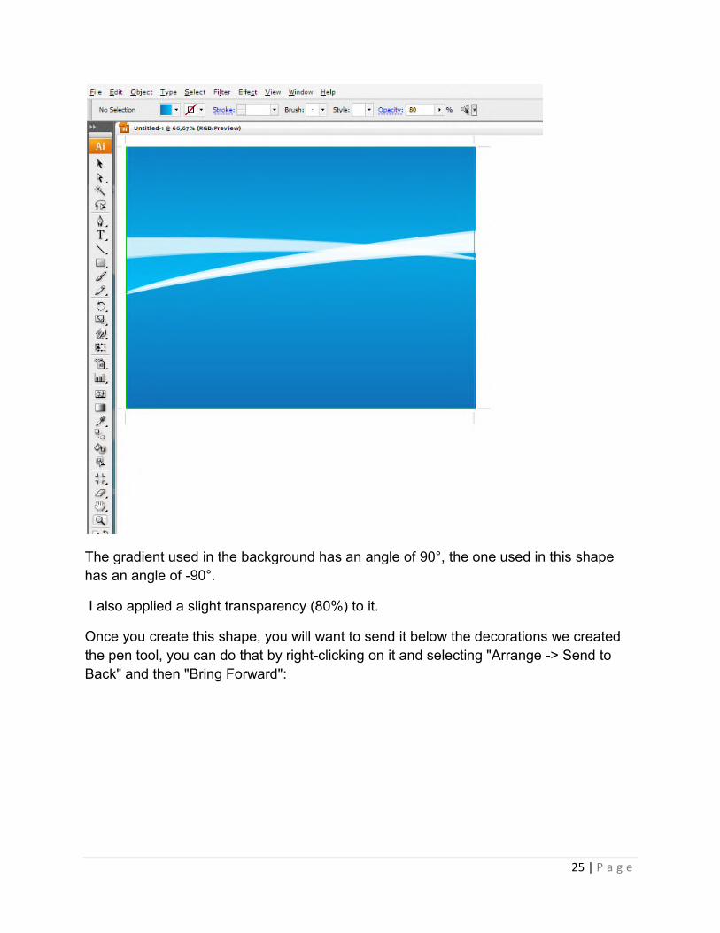
To add some variance we will create a shape that follows loosely the lower-positioned
decoration and add a gradient similar to the one used as a background.
The gradient used in this example has the same colors as the one in the background,
but it has an inverted angle
25 | P a g e
The gradient used in the background has an angle of 90°, the one used in this shape
has an angle of -90°.
I also applied a slight transparency (80%) to it.
Once you create this shape, you will want to send it below the decorations we created
the pen tool, you can do that by right-clicking on it and selecting "Arrange -> Send to
Back" and then "Bring Forward":

26 | P a g e
As you can see this simple operation adds a great deal of variance to our image
Let' s further add some decorations by creating a white circle with an 80% transparency.
We will then duplicate this circle and position it exactly over the first one and with our
direct selection tool (A on the keyboard) we will drag the top anchor point down a bit to
create this effect
We will then proceed to duplicate this decoration a few times, change its overall
transparency, rotate and resize it so we get something that looks like this:

27 | P a g e
Let' s now add some shapes with the pen tool and fill them up with the same gradient as
the background, but with the angle changed to suit our needs.
Position these shapes underneath every other decoration, but obviously above the
background:

28 | P a g e
Let' s add some further white decorations by creating a white rectangle with a 25%
transparency and duplicate it positioning the duplicates over the originals and resizing
them as needed.
Let' s then add some text to give our image some context:
CREATING A BORDER.
The first thing we need to do is creat the little shape that is repeated along the contour.

1. Create a new circle and set the fill to black (or any color you want). Right now you
have this:
2. Go to Object -> Path -> Add anchor points. You sh
3. To give it the flowery border go to: Effect
message box will appear where you can edit the settings. Here is what i used:
4. Create a new circle and fill it (I chose white) and then mover i
make sure it’s perfectly aligned, select both shapes and click the Horizontal Align
Center and Vertical Align Center buttons:
go to Window and check the Control toolbar. Now you should have:
1. Create a new circle and set the fill to black (or any color you want). Right now you
> Add anchor points. You should have this:
3. To give it the flowery border go to: Effect -> Distort & Transform -> Pucker & Bloat. A
message box will appear where you can edit the settings. Here is what i used:
4. Create a new circle and fill it (I chose white) and then mover it over the shape. To
make sure it’s perfectly aligned, select both shapes and click the Horizontal Align
Center and Vertical Align Center buttons: and . If you can’t see the buttons,
go to Window and check the Control toolbar. Now you should have:
29 | P a g e
1. Create a new circle and set the fill to black (or any color you want). Right now you
> Pucker & Bloat. A
message box will appear where you can edit the settings. Here is what i used:
t over the shape. To
make sure it’s perfectly aligned, select both shapes and click the Horizontal Align
. If you can’t see the buttons,

5. Next we’ll convert the shape into a brush. Before doing that, I suggest resizing the
shapes (hold the Shift key down while resizing so it keeps the original proportions). After
that is done, bring up the Brushes toolbar (F5) and click on the options menu
Brush:
Select New Pattern Brush in the dialog that appears:
and then ok in the following dialog box. (you can play with the settings there, but for now
the default ones are good).
6. Draw and oval and for Brush select the brush you just ma
me:
Next we’ll convert the shape into a brush. Before doing that, I suggest resizing the
shapes (hold the Shift key down while resizing so it keeps the original proportions). After
that is done, bring up the Brushes toolbar (F5) and click on the options menu
Select New Pattern Brush in the dialog that appears:
and then ok in the following dialog box. (you can play with the settings there, but for now
6. Draw and oval and for Brush select the brush you just made. Here is how it looks for
30 | P a g e
Next we’ll convert the shape into a brush. Before doing that, I suggest resizing the
shapes (hold the Shift key down while resizing so it keeps the original proportions). After
that is done, bring up the Brushes toolbar (F5) and click on the options menu -> New
and then ok in the following dialog box. (you can play with the settings there, but for now
de. Here is how it looks for
31 | P a g e
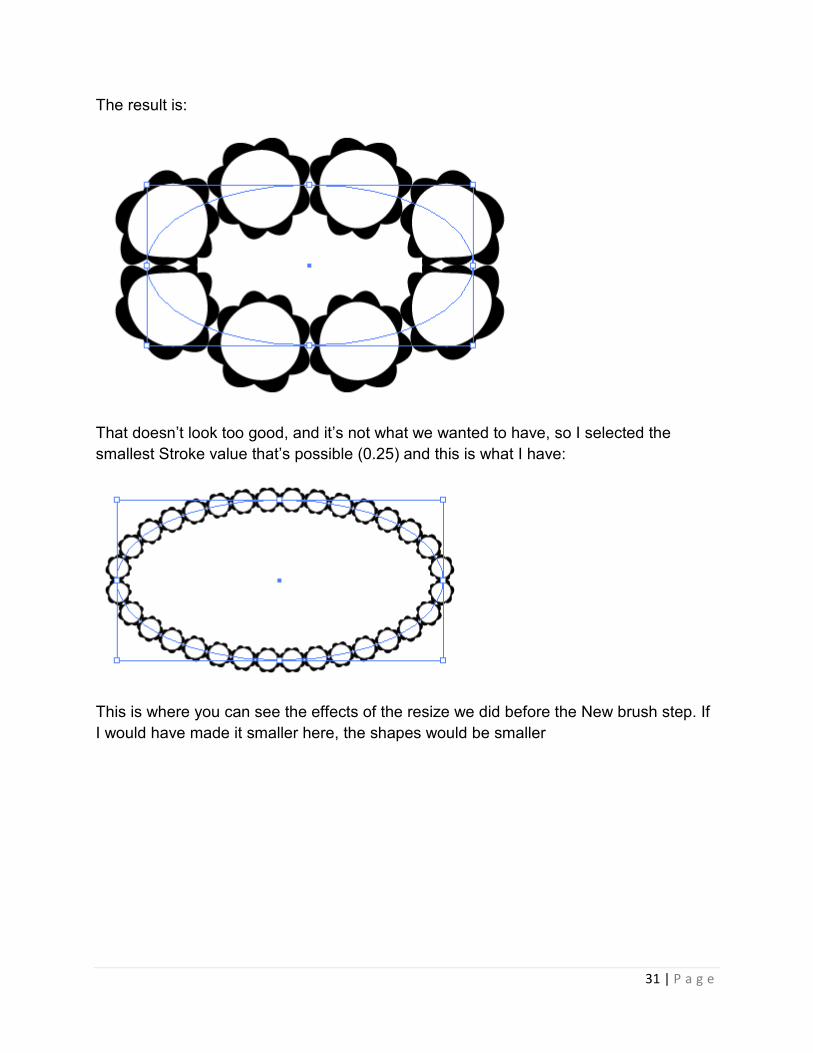
The result is:
That doesn’t look too good, and it’s not what we wanted to have, so I selected the
smallest Stroke value that’s possible (0.25) and this is what I have:
This is where you can see the effects of the resize we did before the New brush step. If
I would have made it smaller here, the shapes would be smaller

32 | P a g e
UNIT– II
Basics of Illustrator
In this lesson, we will look at how to use the shape tools to draw our basic shapes in illustrator. But before we start, we will look at how to select a basic shape so that you have no problems in selecting and editing shapes in Illustrator.
Selection Tools
There are 2 types of selection tool in Illustrator used for selection objects.
Selection Tool: Used for selecting and moving a shape. It can also be used to resize a shape. Direct Selection Tool: Selects a single anchor point instead of the whole shape. Used for editing anchor point of a shape. Click once on a point to select and hold Shift to select multiple anchor points.
Shape Tools
Now we will move on to the Shape Tools. When you go to the Tool Palette and hold the Rectangle Tool, a list of shape tools will expand out for you to pick. We will start with the default Rectangle Tool.

33 | P a g e
Understanding Fill & Stroke
Click and drag out a Rectangle as shown. By default, it has a white fill and black stroke. (Stroke is the border of the shape)
Changing Fill Color
Let’s start changing the fill color for the rectangle. Double click the Fill from the Tool Palette. It will pop up the Color Picker. Drag the slider to blue and select a deep blue color. Click Ok after that.
Removing Stroke
Click the Stroke in the Tool Palette once to swap it above Fill. Click the None icon boxed up in red to set the Stroke to None. The black stroke will disappear.

34 | P a g e
Constrain Proportion
To draw a perfect square, we will select the Rectangle Tool. Hold Shift and drag to draw a square. Same for the circle, we will select the Ellipse Tool and hold Shift to drag out a circle.
Resizing Shape
To resize shapes, select the shape using the Selection Tool and a bounding box will appear. Drag the corner anchor point to resize it. To constrain to proportion while resizing, hold Shift as you resize. Also hold Alt/Option if your want to resize from the same position.

35 | P a g e
Rotating Shapes
Select the shape with the Selection Tool and a bounding box will appear. Move your cursor near the anchor corner and a rotation icon will icon, click and turn it to rotate the square. To snap at 45 degrees increment, hold Shift and turn.
More Options for Shape Tools
Select the Star Tool. Click once on the artboard and an option will pop up. Enter the same values below and click Ok. It will draw a star burst shape. This method can be used to bring out more options for shape tools.
Conclusion
Almost all the objects found in our daily life can be built from combining using the basic shape tools. In Day 9, we will learn about Compound Paths which will help us create more complicated shapes by adding and subtracting from the basic shapes.
Drawing Lines
Use the Line Segment tool when you want to draw one straight line segment at a time.
Select the Line Segment tool .
1. Do one of the following:
� Position the pointer where you want the line to begin, and drag to where
you want the line to end.

36 | P a g e
� Click where you want the line to begin, and specify the length and angle of
the line. If you want to fill the line with the current fill color, select Fill Line.
Then click OK.
Edit paths with the Pencil tool
You can edit any path using the Pencil tool and add freeform lines and shapes to any
shape.
Add to a path with the Pencil tool
1. Select an existing path.
2. Select the Pencil tool.
3. Position the pencil tip on an endpoint of the path.
You can tell you’re close enough to the endpoint when the small x next to the pencil tip
disappears.
4. Drag to continue the path.
Connect two paths with the Pencil tool
1. Select both paths (Shift-click or drag around the two with the Selection tool).
2. Select the Pencil tool.
3. Position the pointer where you want to begin from one path, and start dragging
toward the other path.
4. After you begin dragging, hold down Ctrl (Windows) or Command (Mac OS). The
Pencil tool displays a small merge symbol to indicate you’re adding to the
existing path.
5. Drag onto the endpoint of the other path, release the mouse button, and then
release the Ctrl or Command key.
Note: For best results, drag from one path to the other as if you were simply continuing
the paths in the direction they were created.
Reshape paths with the Pencil tool
1. Select the path you want to change.
2. Position the Pencil tool on or near the path to redraw.

37 | P a g e
You can tell you’re close enough to the path when the small x disappears from the tool.
3. Drag the tool until the path is the desired shape.
Using the Pencil tool to edit a closed shape
Note: Depending on where you begin to redraw the path and in which direction you
drag, you may get unexpected results. For example, you may unintentionally change a
closed path to an open path, change an open path to a closed path, or lose a portion of
a shape.
Draw with the Pencil tool
The Pencil tool works primarily the same way in Adobe Illustrator and InDesign. It lets
you draw open and closed paths as if you were drawing with a pencil on paper. It is
most useful for fast sketching or creating a hand-drawn look. Once you draw a path, you
can immediately change it if needed.
Anchor points are set down as you draw with the Pencil tool; you do not determine
where they are positioned. However, you can adjust them once the path is complete.
The number of anchor points set down is determined by the length and complexity of
the path and by tolerance settings in the Pencil Tool Preferences dialog box. These
settings control how sensitive the Pencil tool is to the movement of your mouse or
graphics-tablet stylus.
Draw freeform paths with the Pencil tool
1. Select the Pencil tool .
2. Position the tool where you want the path to begin, and drag to draw a path. The
Pencil tool displays a small x to indicate drawing a freeform path.
As you drag, a dotted line follows the pointer. Anchor points appear at both ends of the
path and at various points along it. The path takes on the current stroke and fills
attributes, and remains selected by default.
38 | P a g e
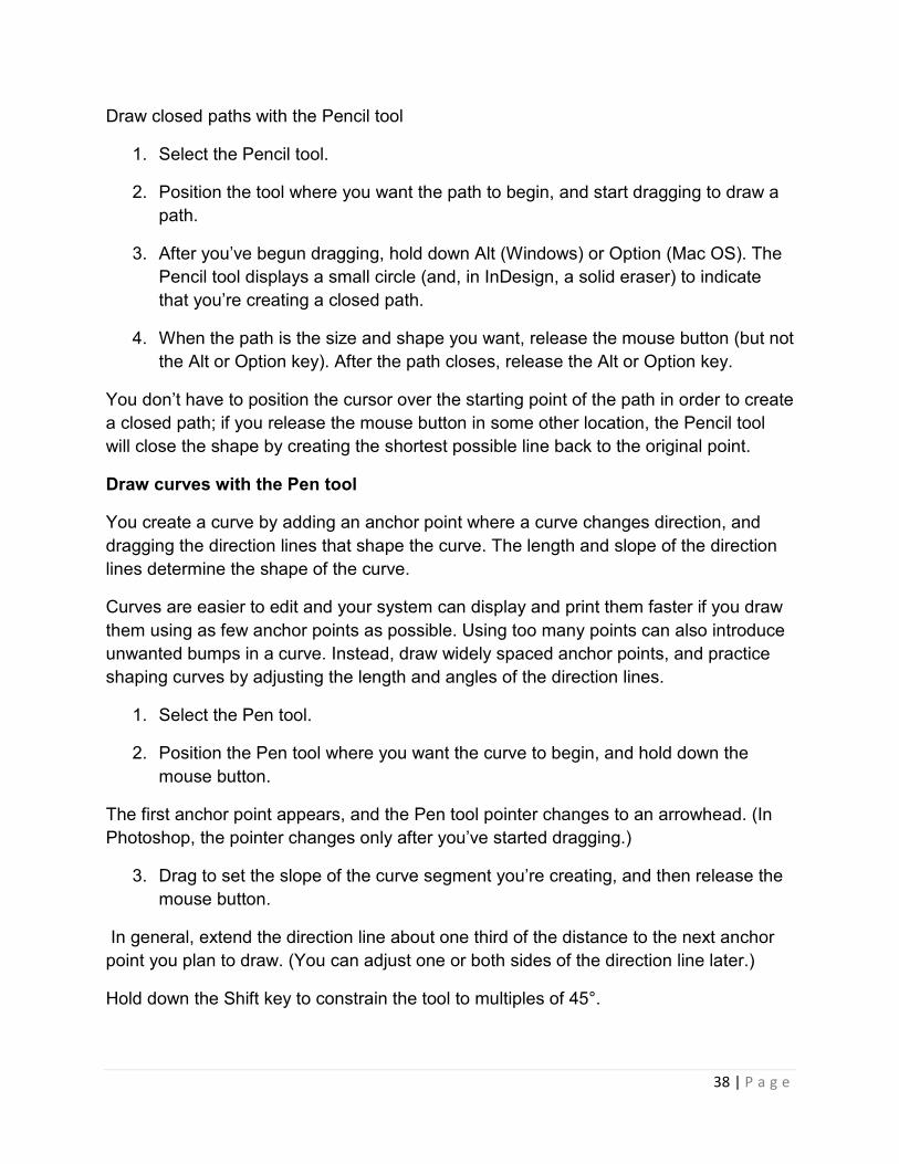
Draw closed paths with the Pencil tool
1. Select the Pencil tool.
2. Position the tool where you want the path to begin, and start dragging to draw a
path.
3. After you’ve begun dragging, hold down Alt (Windows) or Option (Mac OS). The
Pencil tool displays a small circle (and, in InDesign, a solid eraser) to indicate
that you’re creating a closed path.
4. When the path is the size and shape you want, release the mouse button (but not
the Alt or Option key). After the path closes, release the Alt or Option key.
You don’t have to position the cursor over the starting point of the path in order to create
a closed path; if you release the mouse button in some other location, the Pencil tool
will close the shape by creating the shortest possible line back to the original point.
Draw curves with the Pen tool
You create a curve by adding an anchor point where a curve changes direction, and
dragging the direction lines that shape the curve. The length and slope of the direction
lines determine the shape of the curve.
Curves are easier to edit and your system can display and print them faster if you draw
them using as few anchor points as possible. Using too many points can also introduce
unwanted bumps in a curve. Instead, draw widely spaced anchor points, and practice
shaping curves by adjusting the length and angles of the direction lines.
1. Select the Pen tool.
2. Position the Pen tool where you want the curve to begin, and hold down the
mouse button.
The first anchor point appears, and the Pen tool pointer changes to an arrowhead. (In
Photoshop, the pointer changes only after you’ve started dragging.)
3. Drag to set the slope of the curve segment you’re creating, and then release the
mouse button.
In general, extend the direction line about one third of the distance to the next anchor
point you plan to draw. (You can adjust one or both sides of the direction line later.)
Hold down the Shift key to constrain the tool to multiples of 45°.

39 | P a g e
Drawing the first point in a curve
A. Positioning Pen tool
B. Starting to drag (mouse button pressed)
C. Dragging to extend direction lines
4. Position the Pen tool where you want the curve segment to end, and do one of
the following:
� To create a C-shaped curve, drag in a direction opposite to the previous
direction line. Then release the mouse button.
Drawing the second point in a curve
A. Starting to drag second smooth point
B. Dragging away from previous direction line, creating a C curve
C. Result after releasing mouse button
� To create an S-shaped curve, drag in the same direction as the previous
direction line. Then release the mouse button.

40 | P a g e
Drawing an S curve
A. Starting to drag new smooth point
B. Dragging in same direction as previous direction line, creating an S curve
C. Result after releasing mouse button
(Photoshop only) To change the direction of the curve sharply, release the mouse
button, and then Alt-drag (Windows) or Option-drag (Mac OS) the direction point
in the direction of the curve. Release the Alt (Windows) or Option (Mac OS) key
and the mouse button, reposition the pointer where you want the segment to end,
and drag in the opposite direction to complete the curve segment.
Continue dragging the Pen tool from different locations to create a series of smooth
curves. Note that you are placing anchor points at the beginning and end of each curve,
not at the tip of the curve.
Alt-drag (Windows) or Option-drag (Mac OS) direction lines to break out the
direction lines of an anchor point.
Complete the path by doing one of the following:
� To close the path, position the Pen tool over the first (hollow) anchor point.
A small circle appears next to the Pen tool pointer when it is positioned
correctly. Click or drag to close the path.
Note: To close a path in InDesign, you can also select the object and choose Object >
Paths > Close Path.
� To leave the path open, Ctrl-click (Windows) or Command-click (Mac OS)
anywhere away from all objects.
To leave the path open, you can also select a different tool, or choose Select > Deselect
in Illustrator or Edit > Deselect All in InDesign.

41 | P a g e
Select paths, segments, and anchor points
Before you can reshape or edit a path, you need to select the path’s anchor points,
segments, or a combination of both.
Select anchor points
� If you can see the points, you can click them with the Direct Selection tool to
select them. Shift-click to select multiple points.
� Select the Direct Selection tool and drag a boundary around the anchor points.
Shift-drag around additional anchor points to select them.
� Make sure the path that contains the anchor points is not selected. Move the
Direct Selection tool over the anchor point until the pointer displays a hollow
square, and then click the anchor point. Shift-click additional anchor points to
select them.
� (Illustrator only) Select the Lasso tool, and drag around the anchor points. Shift-
drag around additional anchor points to select them.
Select path segments
Do any of the following:
� Select the Direct Selection tool , and click within 2 pixels of the segment, or
drag a marquee over part of the segment. Shift-click or Shift-drag around
additional path segments to select them.
� (Illustrator only) Select the Lasso tool , and drag around part of the path
segment. Shift-drag around additional path segments to select them.
Select all anchor points and segments in a path
1. Select the Direct Selection tool or, in Illustrator, the Lasso tool.
2. Drag around the entire path.
If the path is filled, you can also click inside the path with the Direct Selection tool to
select all anchor points.

42 | P a g e
Copy a path
Select a path or segment with the Selection tool or Direct Selection tool and do one
of the following:
� Use the standard menu functions to copy and paste paths within or between
applications.
� Press and hold Alt (Windows) or Option (Mac OS) and drag the path to the
desired position, and then release the mouse button and Alt/Option key.
Transform using the bounding box
When you select one or more objects with the Selection tool, a bounding box displays
around them. Use the bounding box to easily move, rotate, duplicate, and scale objects
by dragging the object or a handle (one of the hollow squares along the bounding box).
� To hide the bounding box, choose View > Hide Bounding Box.
� To show the bounding box, choose View > Show Bounding Box.
� To reorient the bounding box after you rotate it, choose Object > Transform >
Reset Bounding Box.
Selected objects before (left) compared to after (right) scaling using the bounding box
Scale objects
Scaling an object enlarges or reduces it horizontally (along the x axis), vertically (along
the y axis), or both. Objects scale relative to a reference point which varies depending
on the scaling method you choose. You can change the default reference point for most
scaling methods, and you can also lock the proportions of an object.
By default, strokes and effects are not scaled along with objects. To scale strokes and
effects, choose Edit > Preferences > General (Windows) or Illustrator > Preferences >
General (Mac OS), and select Scale Strokes & Effects. If you want to choose whether to

43 | P a g e
scale strokes and effects on a case-by-case basis, use the Transform panel or the
Scale command to scale objects.
The Scale Strokes & Effects option scales the object, the drop shadow effect, and the
stroke (left); only the object scales when this option is off (right).
Scale objects with the Scale tool
1. Select one or more objects.
2. Select the Scale tool .
3. Do any of the following:
� To scale relative to the object’s center point, drag anywhere in the
document window until the object is the desired size.
� To scale relative to a different reference point , click where you want the
reference point to be in the document window, move the pointer away
from the reference point, and then drag until the object is the desired size.
� To maintain the object’s proportions as it scales, hold down Shift as you
drag diagonally.
� To scale the object along a single axis, hold down Shift as you drag
vertically or horizontally.
For finer control over scaling, start dragging farther from the reference point.
Scale objects with the bounding box
1. Select one or more objects.
2. Select the Selection tool or the Free Transform tool .
3. Drag a bounding box handle until the object is the desired size.

44 | P a g e
Objects scale relative to the opposite handle of the bounding box.
4. Do any of the following to control the scaling behavior:
� To maintain the object’s proportions, hold down Shift as you drag.
� To scale relative to the object’s center point, hold down Alt (Windows) or
Option (Mac OS) as you drag.
Scale objects to a specific width and height
1. Select one or more objects.
2. In the Transform panel, enter a new value in the Width (W) or Height (H) box, or
both.
You can do any of the following before you enter a value to control the scaling behavior:
� To maintain the objects’ proportions, click the lock proportions button .
� To change the reference point for scaling, click a white square on the
reference point locator .
� To scale stroked paths and any size-related effects along with the object,
select Scale Strokes & Effects from the panel menu.
You can also maintain proportions by entering a value in the W or H box, and
then pressing Ctrl (Windows) or Command (Mac OS) while you press Enter.
Scale objects by a specific percentage
1. Select one or more objects.
2. Do one of the following:
� To scale from the center, choose Object > Transform > Scale or double-
click the Scale tool .
� To scale relative to a different reference point, select the Scale tool and
Alt-click (Windows) or Option-click (Mac OS) where you want the
reference point to be in the document window.
In the Scale dialog box, do one of the following:
� To maintain the object’s proportions as it scales, select Uniform, and enter
a percentage in the Scale text box.

45 | P a g e
� To scale the height and width separately, select Non-Uniform, and enter a
percentage in the Horizontal and Vertical text boxes.
The scale factors are relative to the reference point and can be negative or positive.
To scale stroked paths and any size-related effects along with the object, select Scale
Strokes & Effects.
If the objects contain a pattern fill, select Patterns to scale the pattern. Deselect Objects
if you want to scale the pattern but not the objects.
Click OK, or click Copy to scale a copy of the objects.
Scale multiple objects
1. Select the objects.
2. Choose Object > Transform > Transform Each.
3. Set percentages for horizontal and vertical scaling in the Scale section of the
dialog box.
4. To change the reference point, click a white square on the reference point
locator .
5. Click OK, or click Copy to scale a copy of each object
Shear objects
Shearing an object slants, or skews, the object along the horizontal or vertical axis, or a
specified angle that’s relative to a specified axis. Objects shear relative to a reference
point which varies depending on the shearing method you choose and can be changed
for most shearing methods. You can lock one dimension of an object as you shear it,
and you can shear one object or multiple objects simultaneously.
Shearing is useful for creating cast shadows.

46 | P a g e
Shearing relative to the center (left) compared to shearing relative to a user-defined
reference point (right)
Shear objects with the Free Transform tool
1. Select one or more objects.
2. Select the Free Transform tool .
3. Do one of the following:
� To shear along the object’s vertical axis, start dragging the middle-left or
middle-right bounding-box handle, and then hold down Ctrl+Alt (Windows)
or Option+Command (Mac OS) as you drag up or down. You can also
hold down Shift to constrain the object to its original width.
� To shear along the object’s horizontal axis, start dragging the top-middle
or bottom-middle bounding-box handle and then hold down Ctrl+Alt
(Windows) or Option+Command (Mac OS) as you drag right or left. You
can also hold down Shift to constrain the object to its original height.
Distort objects
You can distort objects by using the Free Transform tool or a liquify tool. Use the Free
Transform tool when you want to distort freely; use a liquify tool if you want to take
advantage of specific preset distortions such as twirls, puckers, or wrinkles.
Distort objects with the Free Transform tool
1. Select one or more objects.
2. Select the Free Transform tool .
3. Start dragging a corner handle on the bounding box (not a side handle), and then
do one of the following:
� Hold down Ctrl (Windows) or Command (Mac OS) until the selection is at
the desired level of distortion.
� Hold down Shift+Alt+Ctrl (Windows) or Shift+Option+Command (Mac OS)
to distort in perspective.

47 | P a g e
Distorting in perspective
Distort objects using a liquify tool
You cannot use liquify tools on linked files or objects that contain text, graphs, or
symbols.
1. Select a liquify tool, and click or drag over the objects you want to distort.
2. (Optional) To isolate the distortion to specific objects, select the objects before
using the tool.
3. (Optional) To change the size of the tool cursor and set other tool options,
double-click the liquify tool and specify any of the following:
Width and Height
Controls the size of the tool cursor.
Angle
Controls the orientation of the tool cursor.
Intensity
Specifies the rate of change for the distortion. Higher values equal faster changes.
Use Pressure Pen
Uses the input from a tablet or pen instead of the Intensity value. If you don’t have a
pressure-sensitive tablet attached, this option is dimmed.
Complexity (Scallop, Crystallize, and Wrinkle tools)
Specifies how closely the results of the particular brush are spaced on the object’s
outline. This is closely tied with the Detail value.

48 | P a g e
Detail
Specifies the spacing between points introduced into the object’s outline (higher values
space points closer together).
Simplify (Warp, Twirl, Pucker, and Bloat tools)
Specifies how much you want to reduce the superfluous points that do not measurably
affect the overall appearance of the shape.
Twirl Rate (Twirl tool only)
Specifies the rate at which the twirl is applied. Enter a value between –180° and 180°.
Negative values twirl the object clockwise and positive values twirl counterclockwise.
The object twirls faster with values that are closer to either –180° or 180°. To twirl
slowly, specify a rate close to 0°.
Horizontal and Vertical (Wrinkle tool only)
Specifies how far apart the control points are placed.
Brush Affects Anchor Points, Brush Affects In Tangent Handles, or Brush Affects
Out Tangent Handles (Scallop, Crystallize, Wrinkle tools)
Enables the tool brush to make changes to these properties

49 | P a g e
UNIT– III
IMAGE STROKES
INTRODUCTION-BRUSH
Brushes let you stylize the appearance of paths. You can apply brush strokes to existing
paths, or you can use the Paintbrush tool to draw a path and apply a brush stroke
simultaneously.
There are four types of brushes in Illustrator—calligraphic, scatter, art, and pattern. You
can achieve the following effects using these brushes:
Calligraphic brushes
Create strokes that resemble those drawn with the angled point of a calligraphic pen
and are drawn along the center of the path.
Scatter brushes
Disperse copies of an object (such as a ladybug or a leaf) along the path.
Art brushes
Stretch a brush shape (such as Rough Charcoal) or object shape evenly along the
length of the path.
Pattern brushes
Paint a pattern—made of individual tiles—that repeats along the path. Pattern brushes
can include up to five tiles, for the sides, inner corner, outer corner, beginning, and end
of the pattern.

50 | P a g e
Sample brushes - A. Calligraphic brush B. Scatter brush C. Art brush D. Pattern
brush
Scatter brushes and Pattern brushes can often achieve the same effect. However, one
way in which they differ is that Pattern brushes follow the path exactly, while Scatter
brushes do not.
Arrows in a Pattern brush bend to follow the path (left), but arrows remain
straight in a Scatter brush (right).
DRAW ARCS
1. Select the Arc tool .
2. Do one of the following:
� Position the pointer where you want the arc to begin, and drag to where
you want the arc to end.
� Click where you want the arc to begin. In the dialog box, click a square on
the reference point locator to determine the point from which the arc is
drawn. Then set any of the following options, and click OK.
Length X-axis Specifies the width of the arc.
Length Y-axis Specifies the height of the arc.
Type Specifies whether you want the object to be an open path or a closed
path.
Base Along Specifies the direction of the arc. Choose X Axis or Y Axis
depending on whether you want to draw the base of the arc along the horizontal (x) axis
or vertical (y) axis.

51 | P a g e
Slope Specifies the direction of the arc’s slope. Enter a negative value for
a concave (inward) slope. Enter a positive value for a convex (outward) slope. A slope
of 0 creates a straight line.
Fill Arc Fills the arc with the current fill color
DRAW SPIRALS
1. Select the Spiral tool .
2. Do one of the following:
� Drag until the spiral is the desired size. Drag the pointer in an arc to rotate
the spiral.
� Click where you want the spiral to begin. In the dialog box, set any of the
following options, and click OK.
Radius Specifies the distance from the center to the outermost point in the spiral.
Decay Specifies the amount by which each wind of the spiral should
decrease relative to the previous wind.
Segments Specifies how many segments the spiral has. Each full wind of the spiral
consists of four segments.
Style Specifies the direction of the spiral.
DRAW GRIDS
Use the grid tools to quickly draw rectangular and polar grids. The Rectangular Grid tool
creates rectangular grids of a specified size with a specified number of dividers. The
Polar Grid tool creates concentric circles of a specified size and a specified number of
dividers.
DRAW RECTANGULAR GRIDS
1. Select the Rectangular Grid tool .
2. Do one of the following:
� Drag until the grid is the desired size.

52 | P a g e
� Click to set the grid’s reference point. In the dialog box, click a square on
the reference point locator to determine the point from which the grid is
drawn. Then set any of the following options, and click OK.
Default Size Specifies the width and height of the entire grid.
Horizontal Dividers Specifies the number of horizontal dividers you want to
appear between the top and bottom of the grid. The Skew value determines how the
horizontal dividers are weighted toward the top or bottom of the grid.
Vertical Dividers Specifies the number of dividers you want to appear between the
left and right sides of the grid. The Skew value determines how the vertical dividers are
weighted to the left or right side.
Use Outside Rectangle As Frame Replaces the top, bottom, left, and right
segments with a separate rectangular object.
Fill Grid Fills the grid with the current fill color (otherwise, the fill is set to none).
DRAW CIRCULAR (POLAR) GRIDS
1. Select the Polar Grid tool .
2. Do one of the following:
� Drag until the grid is the desired size.
� Click to set the grid’s reference point. In the dialog box, click a square on
the reference point locator to determine the point from which the grid is
drawn. Then set any of the following options, and click OK.
Default Size Specifies the width and height of the entire grid.
Concentric Dividers Specifies the number of circular concentric dividers you want
to appear in the grid. The Skew value determines how the concentric dividers are
weighted toward the inside or outside of the grid.
Radial Dividers Specifies the number of radial dividers you want to appear between
the center and the circumference of the grid. The Skew value determines how the radial
dividers are weighted counterclockwise or clockwise on the grid.
Create Compound Path From Ellipses Converts the concentric circles into
separate compound paths and fill every other circle.
Fill Grid Fills the grid with the current fill color (otherwise, the fill is set to none).

53 | P a g e
ADOBE ILLUSTRATOR GRAPH TOOLS LET YOU CREATE NINE DIFFERENT
GRAPH TYPESCOLUMN
The default graph type. It compares one or more sets of values by using rectangles
whose lengths are proportional to the values.
STACKED COLUMN
Similar to a column graph, but stacks the columns on top of one another, instead of side
by side. This graph type is useful for showing the relationship of parts to the total.
BAR
Similar to a column graph, but positions the rectangles horizontally instead of vertically.
STACKED BAR
Similar to a stacked column graph, but stacks the bars horizontally instead of vertically.
LINE
Uses points to represent one or more sets of values, with a different line joining the
points in each set. This type of graph is often used to show the trend of one or more
subjects over a period of time.
AREA
Similar to a line graph, but emphasizes totals as well as changes in values.
SCATTER
Plots data points as paired sets of coordinates along the x and y axes. Scatter graphs
are useful for identifying patterns or trends in data. They also can indicate whether
variables affect one another.
PIE
A circular graph whose wedges represent the relative percentages of the values
compared.
RADAR
The Radar Graph tool creates graphs that compare sets of values at given points in
time or in particular categories, and is displayed in a circular format. This type of graph
is also called a web graph.

54 | P a g e
TYPESCOLUMN STACKED COLUMN LINE
STACKED BAR LINE AREA
SCATTER PIE RADAR

55 | P a g e
GRAPH DATA
You use the Graph Data window to enter the data for your graph. The Graph Data
window appears automatically when you use a graph tool and stays open until you
close it.
Graph data window
A. Entry text box B. Import data C. Transpose row/column
D. Switch x/y E. Cell style F. Revert G. Apply
1. Display the Graph Data window for an existing graph: select the entire graph with
the Selection tool, and then choose Object > Graph > Data.
2. Enter data in any of the following ways:
� Select a cell in the worksheet, and enter the data in the text box at the top
of the window. Press Tab to input the data and select the next cell in the
same row; press Enter or Return to input the data and select the next cell
in the same column; use the arrow keys to move from cell to cell; or simply
click another cell to select it.
� Copy data from a spreadsheet application such as Lotus® 1-2-3 or
Microsoft Excel. In the Graph Data window, click the cell that will be the
upper-left cell of the data you paste, and choose Edit > Paste.
� Use a word-processing application to create a text file in which the data for
each cell is separated by a tab, and the data for each row is separated by
a paragraph return. The data can only contain decimal points or decimal
commas; otherwise, the data is not plotted. (For example, enter 732000,
not 732,000.) In the Graph Data window, click the cell that will be the
upper-left cell of the data you import, click the Import Data button , and
select the text file.

56 | P a g e
Note: If you accidentally enter graph data backward (that is, in rows instead of columns,
or vice versa), click the Transpose button to switch the columns and rows of data. To
switch the x and y axes of scatter graphs, click the Switch X/Y button .
Click the Apply button or press the Enter key on the numeric keypad to regenerate
the graph
FORMATTING AND CUSTOMIZING GRAPHS
Graphs can be formatted in a variety of ways. For example, you can change the
appearance and position of the graph’s axes, add drop shadows, move the legend, and
combine different graph types. You can view the formatting options for a graph by
selecting a graph with the Selection tool and choosing Object > Graph > Type.
You can also manually customize your graph in numerous ways. You can change the
colors of shading; change the typeface and type style; move, reflect, shear, rotate, or
scale any or all parts of the graph; and customize column and marker designs. You can
apply transparency, gradients, blends, brush strokes, graphic styles, and other effects to
graphs. You should always apply these types of changes last, because regenerating the
graph will remove them.
To get ideas for how you can customize graphs, see the examples in the Cool
Extras/Sample Files/Graph Designs folder inside the Illustrator application folder.
Keep in mind that a graph is a grouped object that is related to its data. Never ungroup
the graph; if you do, you cannot change the graph. To edit a graph, select the parts you
want to edit without ungrouping the graph, using either the Direct Selection tool or the
Group Selection tool.
It is also important to understand how elements of a graph are related. The entire graph
with its legends is one group. All the sets of data are a subgroup of the graph; in turn,
each set of data with its legend box is a subgroup of all the sets of data. Each value is a
subgroup of its set of data, and so on. Never ungroup or regroup objects that are within
the graph.
Labels are words or numbers that describe two things: the sets of data you want to
compare, and the categories across which you want to compare them. For column,
stacked column, bar, stacked bar, line, area, and radar graphs, you enter labels in the
worksheet as follows:

57 | P a g e
Labels in Graph Data window
A. Data set labels B. Blank cell C. Category labels
Enter labels
For column, stacked column, bar, stacked bar, line, area, and radar graphs, enter
labels in the worksheet as follows:
� If you want Illustrator to generate a legend for the graph, delete the contents of
the upper-left cell and leave the cell blank.
� Enter labels for the different sets of data in the top row of cells. These labels will
appear in the legend. If you don’t want Illustrator to generate a legend, don’t
enter data-set labels.
� Enter labels for the categories in the left column of cells. Categories are often
units of time, such as days, months, or years. These labels appear along either
the horizontal axis or vertical axis of the graph, with the exception of radar
graphs, for which each label results in a separate axis.
� To create labels consisting only of numbers, enclose the numbers in straight
quotation marks. For example, to use the year 1996 as a label, enter "1996".
� To create line breaks in labels, use the vertical bar key to separate lines.
For example, type Total|subscriptions|1996 to produce the following graph
label:
Total
subscriptions
1996

58 | P a g e
Enter data sets for scatter graphs
A scatter graph differs from the other kinds of graphs in that both axes measure values;
there are no categories.
Scatter graph data
� Enter data-set labels in every other cell along the top row of the worksheet,
starting with the first cell. These labels will appear in the legend.
� Enter y-axis data in the first column and x-axis data in the second column.
Enter data sets for pie graphs
You organize data sets for pie graphs similarly to other graphs. However, each row of
data in the worksheet generates a separate graph.
Pie graph data
� Enter data-set labels as for column, stacked column, bar, stacked bar, line, area,
and radar graphs. Enter category labels if you want to generate graph names.

59 | P a g e
� To create a single pie graph, plot only one row of data, either all positive or all
negative values.
� To create multiple pie graphs, plot additional rows of data, either all positive or all
negative values. By default, the size of the individual pie graphs is proportional to
the total of each graph’s data.
Enter data sets for column, bar, line, area, and radar graphs
After you enter the labels for your graph, you’re ready to enter each set of data under
the appropriate column.
Column graph data
Column, stacked column, bar, stacked bar graphs
The height of the column or length of the bar corresponds to the amount being
compared. For column or bar graphs, you can combine positive and negative values;
negative values appear as columns extending below the horizontal axis. For stacked
column graphs, numbers must be all positive or all negative.
Line graphs
Each column of data corresponds to one line in the line graph. You can combine
positive and negative values in a line graph.
Area graphs
Values must be all positive or all negative. Each row of data entered corresponds to a
filled area on the area graph. Area graphs add each column’s values to the previous
column’s totals. Therefore, even if area graphs and line graphs contain the same data,
they appear substantially different.

60 | P a g e
Radar graphs
Each number is plotted on an axis and connected to the others in the same axis to
create a “web.” You can combine positive and negative values in a radar graph

61 | P a g e
UNIT– IV
Image Grouping
Free Transform Tool Attributes The "Free Transform" tool is located in Adobe Illustrator's "Tool Palette." To activate this tool, click on its symbol in the Adobe's Tool Palette (left) or you can use the keyboard shortcut "E" to access the "Free Transform" tool. Illustrator's "Free Transform" tool is used to distort the shape of a selected path or series of paths. This is different from the "Rotate Tool" which only turns or rotates a selection. The Free Transform tool is similar to the "Envelope Distort" tool but I feel that "Free Transform" provides more predictable results. To use this tool you would select a path, object, or grouping of objects by dragging your cursor over them while the "Selection Tool (V)" (the solid arrow) is active. Once you create your selection, a "Bounding Box" will appear around the selected objects. Once the bounding box appears, you then select the Free Transform tool. The free transform tool has three distinct attributes. When a selection is highlighted, the cursor becomes a rotational (semi-circle) arrow when the cursor is outside of the bounding box (Fig. A). By dragging this semi-circular arrow, you would rotate the object but no distortion would take place. When you "mouse-over" one of the corners of the bounding box, the cursor becomes a diagonal double sided arrow (Fig. B). If you were to click and drag this arrow you would re-size the bounding box but again, no distortion would take place. The way you make the Free Transform tool do its intended job (distortion) is to click a corner of the bounding box and while holding the click you hit the Command (Control for Windows) key. This will turn the cursor into a single arrowhead (Fig. C). In (Fig. D) we have a grouping of objects that have been highlighted (made active) by using the selection tool. You will notice that when we mouse-over the upper left corner of the Bounding Box we get the double-sided diagonal arrow. When we click-hold the corner our cursor becomes a single arrowhead (Fig. D). We are now ready to distort the image by dragging the corner.

62 | P a g e
Maximizing the "Free Transform" Tool
For our test subject we are going to take our overhead or "plan view" line-art of a passenger vehicle (Fig. 1) and distort it into a predetermined perspective (Fig. 2) using the Free Transform tool.
Prior to distorting our subject matter we will create a Perspective Grid (Fig. 3) using the techniques covered in the 2 Point Perspective Drawing tutorial. This perspective grid will serve as a template for distorting the line-art image.
Before distorting a grouping of objects, we will need to use a function called "Reset Bounding Box" to control the way in which the Bounding Box behaves. If we were not to use this procedure, each time we attempt to align one corner, another corner will move out of alignment (Fig. 4). It would take many attempts to finally align everything up and be a very frustrating endeavor.

63 | P a g e
Resetting the "Bounding Box" In order to control the bounding box we will take several steps that will enable us to distort out subject matter in a minimum of moves. The first step will be to take our vehicle overhead (Fig. 5) and group everything together by selecting all of the paths and using the keyboard's Command>G keys. The next step will be to surround the vehicle with a colored box (Fig. 6). As you can see in (Fig. 7) when we rotate the bounding box using the Free Transform tool the bounding box keeps its orientation aligned with the "Art Board" or background. We will need to have the bounding box maintain the orientation of the selection as shown in (Fig. 8). To accomplish this task, make sure to highlight (activate) the subject with the selection tool and while they are active go to: Object>Transform>Reset Bounding Box in the menu bar before you attempt to rotate and/or distort it. This will keep multiple objects from confusing the orientation of the Bounding Box once you start moving and distorting it.

64 | P a g e
The next step will be to create a template outline of the exact shape that we will be distorting out subject into (Fig. 9). Trace over the perspective grid in a different color (blue in this case) by following the outline of the shape.
Next we will take our perspective template (blue outline in Fig. 9) and rotate it so that the bottom edge is horizontal to the page (Fig. 10). The reason for this step is to have the bounding box anchor-points stay as close to the four outside corners of the image (in this case, the car) as possible. By making most of the distortion moves along this horizontal plane the bounding box (and its anchor-points) doesn’t end up in random locations (see Fig. 4 above). This becomes especially problematic after your first movement, making it much harder to do each subsequent movement. The more movements, the worse it gets.
Align the lower right hand corner of the vehicle image with the lower right corner of the blue line template (Fig. 10). Using the Free Transform tool, stretch the vehicle line-art (using the double-sided arrow cursor on the left-center bounding box square) until the lower left corners align (Fig. 11). Now click on the upper center square of the bounding box (Fig. 12) and Command>Drag it down and to the left until the upper left corners align. The last step will be to Command>Drag the upper-right corner of the bounding box (Fig. 11) until it aligns with the blue template. This will throw the lower-left corner slightly out of alignment but it will be easy to Command>Drag the lower-left bounding box corner back into alignment.

65 | P a g e
The last step will be to rotate the distorted perspective view of the vehicle into place (Fig. 12). For this task we will be using the "Rotate" tool. Align the lower-right corner of the distorted vehicle line-art with the lower-right corner of the perspective grid. Rotate the image using the lower-right corner as an anchor point.
Our last example shows the distorted vehicle line-art properly placed into the perspective grid. (below). This may seem like a lot of steps to achieve something that would seem to be relatively simple but if you have tried to use the Free Transform tool, you know how aggravating it can be if used improperly.
The Illustrator Gradient Tool (G) is accessed through Illustrator's Tool palette (Fig. 1). Once a simple gradation has been created it is controlled through the Gradient palette shown in Fig. 2. A gradation is created by selecting a contained shape (square shown in Fig. 3) and dragging across it with the Gradient Tool (G). You will notice that the white-to-black gradation is indicated in the Gradient palette shown in Fig. 2.

66 | P a g e
Gradient Mesh Tool Attributes Tonal gradations can also be created via Illustrator's Gradient Mesh tool (U). This tool is used to render complex gradations and shapes. It is also accessed through Illustrator's Tool palette (Fig. 4). Once a gradient "Mesh" has been created (Fig. 5) you will notice a grid pattern overlaying your shape. The grid is controlled in much the same way as you would control Illustrator's Pen Tool. You can drag anchor points and add them just as you would with the Pen tool. Unlike the Gradient Tool (G), the Gradient Mesh tool does not make use of the Illustrator Gradient Palette shown in Fig. 6. It is totally controlled by manipulating the anchor points on the grid "mesh". You will notice that the center anchor point in Fig. 5 is active (solid) and that the grey color it is introducing into our black square is shown as the "Fill" color on the Tool palette (Fig. 4).
Using the Gradient Tool's Linear & Radial Settings In this demonstration we will create a matt finished metal tube using only the Illustrator Gradient Tool (G). For this type of gradation we will "Gradient" Palette to "Linear" in the pull-down menu. By clicking on the gradient bar in the Gradient Palette (Fig. 8), you can add new gradation points. This gives you the multiple banding effect that is necessary to render a reflective metallic surface. You will see that our new gradation is shown as the

67 | P a g e
"Fill" color on the Illustrator Tool palette (Fig. 7). You control the color that each new gradation point introduces by double clicking on that point and using the "Color Palette" to modify its color properties. In Fig. 9 we have hardened up the gradation to simulate a highly reflective chrome surface. This is achieved by moving the gradation points closer together thereby shortening the span of each gradation step.
In this palette window you can also adjust the angle of the gradation from 0º to 360º by using the "Angle" setting in the pull-down menu. In our example above we have set the angle to zero degrees. If you were illustrating a sphere instead of tubing you would set the "Gradient" palette to "Radial" in the pull-down menu. This would create a radial gradation that emanates from the center of your defined path. Using the Gradient Mesh Tool In this next demonstration we will create a convex shape using the Illustrator Gradient Mesh tool (U). We will start out with a simple shape (Fig. 11). Once a gradient "Mesh" has been established to our shape (Fig. 12) you will see our grid pattern overlaying the shape. At this stage all anchor points are active (solid). Now we will click on the center anchor point to activate it and deactivate all of the other surrounding points. Once again you will notice that the center anchor point in Fig. 13 is active (solid) and that the white color it is introducing into our grey shape is shown as the "Fill" color on the Tool palette (Fig. 10). As was stated in the preceding paragraph, you can control the illusion of shape by dragging or adding anchor points to the mesh grid. This will change the location and intensity of the gradation thereby affecting the shape. Remember to control the mesh anchor points in the same way that you would control the anchor points along a Path or Stoke.

68 | P a g e
In Fig. 14 we see our shape as it is integrated into the final image. All of the anchor points have been selected and the "Fill" color on the Tool palette will show a "Question Mark" to indicate that there are multiple colors at work in the selection.
Pushing the Limits of Illustrator's Gradient Mesh This is a very basic lesson in the use of the Illustrator Gradient Mesh tool and its ability to create smooth gradations and blends. Using the techniques discussed in this tutorial there is no limit to the complexity of the subject matter you can render with these tools. For an example of just how far you can take Adobe Illustrator's Gradient Tools, check out the article on Yukio Miyamoto's work in Illustrator (samples below).
Perhaps the single greatest limitation on how far you can go with this tool is the file size, and its ability to drastically slow down screen redraws. This is especially annoying when

69 | P a g e
dragging the file with the Hand Tool while zoomed in to the image. If this is the case, you will want to set the "View" mode to "Outline" which will turn off the tonal color work, thereby speeding up screen redraws
In Adobe Illustrator CS, tonal gradations are rendered via the Gradient Mesh tool (U) and the Gradient Tool (G). The Gradient tool is fairly straightforward in its approach to rendering a gradation and blending subtle tonal and color gradations. On the other hand, the Gradient Mesh tool is one of the more labor intensive and frustrating tools in the Illustrator tool pallet, especially for the Illustrator newcomer. Once you become comfortable with this tool you can create seamless blends and gradations that are infinitely scalable in vector format, making the final file far more versatile than a Photoshop raster file. Gradient Pallet Attributes The Illustrator Gradient Tool (G) is accessed through Illustrator's Tool pallet (Fig. 1). Once a simple gradation has been created it is controlled through the Gradient Pallet shown in Fig. 2. A gradation is created by selecting a contained shape (square shown in Fig. 3) and dragging across it with the Gradient Tool (G). You will notice that the white-to-black gradation is indicated in the Gradient Pallet shown in Fig. 2.
Gradient Mesh Tool Attributes Tonal gradations can also be created via Illustrator's Gradient Mesh tool (U). This tool is used to render complex gradations and shapes. It is also accessed through Illustrator's Tool pallet (Fig. 4). Once a gradient "Mesh" has been created (Fig. 5) you will notice a grid pattern overlaying your shape. The grid is controlled in much the same way as you would control Illustrator's Pen Tool. You can drag anchor points and add them just as you would with the Pen tool.

70 | P a g e
Using the Gradient Tool's Linear & Radial Settings In this demonstration we will create a matt finished metal tube using only the Illustrator Gradient Tool (G). For this type of gradation we will "Gradient" pallet to "Linear" in the pull-down menu. By clicking on the gradient bar in the Gradient Pallet (Fig. 8), you can add new gradation points. This gives you the multiple banding effect that is necessary to render a reflective metallic surface. You will see that our new gradation is shown as the "Fill" color on the Illustrator Tool Pallet (Fig. 7). You control the color that each new gradation point introduces by double clicking on that point and using the "Color Pallet" to modify its color properties. In Fig. 9 we have hardened up the gradation to simulate a highly reflective chrome surface. This is achieved by moving the gradation points closer together thereby shortening the span of each gradation step.
In this pallet window you can also adjust the angle of the gradation from 0º to 360º by using the "Angle" setting in the pull-down menu. Inour example above we have set the angle to zero degrees. If you were illustrating a sphere instead of tubing you would set the "Gradient" pallet to "Radial" in the pull-down menu. This would create a radial gradation that emanates from the center of your defined path. Using the Gradient Mesh Tool In this next demonstration we will create a convex shape using the Illustrator Gradient Mesh tool (U). We will start out with a simple shape (Fig. 11). Once a gradient "Mesh" has been established to our shape (Fig. 12) you will see our grid pattern overlaying the shape. At this stage all anchor points are active (solid).

71 | P a g e
Now we will click on the center anchor point to activate it and deactivate all of the other surrounding points. Once again you will notice that the center anchor point in Fig. 13 is active (solid) and that the white color it is introducing into our grey shape is shown as the "Fill" color on the Tool Pallet (Fig. 10). As was stated in the preceding paragraph, you can control the illusion of shape by dragging or adding anchor points to the mesh grid. This will change the location and intensity of the gradation thereby affecting the shape. Remember to control the mesh anchor points in the same way that you would control the anchor points along a Path or Stoke. In Fig. 14 we see our shape as it is integrated into the final image. All of the anchor points have been selected and the "Fill" color on the Tool Pallet will show a "Question Mark" to indicate that there are multiple colors at work in the selection.

72 | P a g e
UNIT–V
Symbols
A symbol is an art object that you can reuse in a document. For example, if you create
a symbol from a flower, you can then add instances of that symbol multiple times to
your artwork without actually adding the complex art multiple times. Each symbol
instance is linked to the symbol in the Symbols panel or to a symbols library. Using
symbols can save you time and greatly reduce file size.
Symbols also provide excellent support for SWF and SVG export. When you export to
Flash, you can set the symbol type to Movie Clip. Once in Flash, you can choose
another type if necessary. You can also specify 9-slice scaling in Illustrator so that the
movie clips scale appropriately when used for user interface components.
After you place a symbol, you can edit the symbol’s instances on the artboard and, if
you want, redefine the original symbol with the edits. The symbolism tools let you add
and manipulate multiple symbol instances at once.
Artwork with symbol instances

73 | P a g e
Editing symbols
Illustrator doesn't edit symbol artwork in the same way Flash does (double-clicking and
making changes that are reflected in all instances). Instead, to edit a symbol, select an
instance on the canvas, press the Break Link to Symbol button on the Symbols palette,
and edit the artwork. When you're ready to update the symbol, make sure the symbol is
selected in the Symbols palette, select the artwork, and choose Redefine Symbol from
the flyout menu on the Symbols palette. You could also hold down Opt/Alt and drag the
edited artwork onto the symbol in the palette.
Transforming instances
Illustrator allows you to apply transformations and effects both inside a symbol and to its
instances. If file size is a concern, stick to instance transformations that Flash can
handle natively (scale, skew, rotate, and fade), and apply other effects inside the
symbol so that they can be reused. For example, applying a drop shadow inside a
symbol vs. outside can cut the file size from 60kb to 5kb (shown here). Also be careful
about applying effects like warps to symbol instances. If necessary Illustrator will
convert symbols into paths on export to preserve an effect (shown here).
Bitmaps and symbols
Symbols in Illustrator can contain bitmaps (including bitmaps with soft-edged
transparency), making it possible to create efficient SWFs using bitmaps inside symbols
(the example below is 9kb). Note that you can set bitmap options (lossless/GIF or
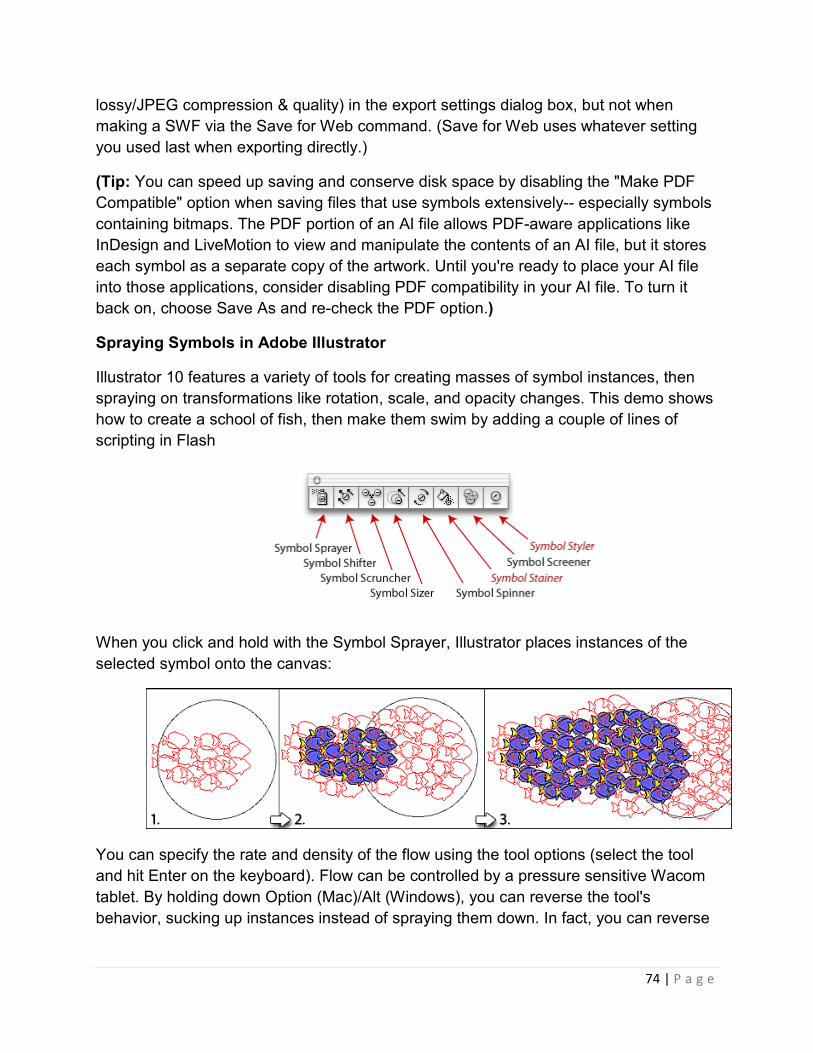
74 | P a g e
lossy/JPEG compression & quality) in the export settings dialog box, but not when
making a SWF via the Save for Web command. (Save for Web uses whatever setting
you used last when exporting directly.)
(Tip: You can speed up saving and conserve disk space by disabling the "Make PDF
Compatible" option when saving files that use symbols extensively-- especially symbols
containing bitmaps. The PDF portion of an AI file allows PDF-aware applications like
InDesign and LiveMotion to view and manipulate the contents of an AI file, but it stores
each symbol as a separate copy of the artwork. Until you're ready to place your AI file
into those applications, consider disabling PDF compatibility in your AI file. To turn it
back on, choose Save As and re-check the PDF option.)
Spraying Symbols in Adobe Illustrator
Illustrator 10 features a variety of tools for creating masses of symbol instances, then
spraying on transformations like rotation, scale, and opacity changes. This demo shows
how to create a school of fish, then make them swim by adding a couple of lines of
scripting in Flash
When you click and hold with the Symbol Sprayer, Illustrator places instances of the
selected symbol onto the canvas:
You can specify the rate and density of the flow using the tool options (select the tool
and hit Enter on the keyboard). Flow can be controlled by a pressure sensitive Wacom
tablet. By holding down Option (Mac)/Alt (Windows), you can reverse the tool's
behavior, sucking up instances instead of spraying them down. In fact, you can reverse

the behavior of most of the symbolism tools by holding Opt/Alt (making instances
smaller instead of larger, more opaque instead of more transparent, etc.):
Note: most, but not all, of the symbolism tools can work efficiently SWFs. The Symbol
Stainer (tinter) and Symbol Styler apply transformations that can't be represented
directly in Flash, meaning that Illustrator will generate new symbols for affected
instances
Create a few symbols to spray with
First of all you need to create a few symbols to have a bit of variation to work with.
Instead of creating a symbol of only one leaf, I suggest to draw groups of leaves and
make them separate symbols. To do this,
drop them in the Symbols palette. I've used different shades of green for my leafs.
Set the Symbol Sprayer Tool
The second step is to double click the Symbol Sprayer Tool in the Toolbox and adjust
the settings to your wishes. This can be a bit tricky and you might need to experiment a
bit to find the setting that fits your purpose. I've used an intensity of 7 and a Symbol Set
Density of 5. Furthermore I've changed all dropdown menus to "User Defined".
the behavior of most of the symbolism tools by holding Opt/Alt (making instances
smaller instead of larger, more opaque instead of more transparent, etc.):
most, but not all, of the symbolism tools can work efficiently SWFs. The Symbol
Stainer (tinter) and Symbol Styler apply transformations that can't be represented
directly in Flash, meaning that Illustrator will generate new symbols for affected
Create a few symbols to spray with
First of all you need to create a few symbols to have a bit of variation to work with.
Instead of creating a symbol of only one leaf, I suggest to draw groups of leaves and
make them separate symbols. To do this, just select the group of leaves and drag &
drop them in the Symbols palette. I've used different shades of green for my leafs.
Set the Symbol Sprayer Tool
The second step is to double click the Symbol Sprayer Tool in the Toolbox and adjust
to your wishes. This can be a bit tricky and you might need to experiment a
bit to find the setting that fits your purpose. I've used an intensity of 7 and a Symbol Set
Density of 5. Furthermore I've changed all dropdown menus to "User Defined".
75 | P a g e
the behavior of most of the symbolism tools by holding Opt/Alt (making instances
smaller instead of larger, more opaque instead of more transparent, etc.):
most, but not all, of the symbolism tools can work efficiently SWFs. The Symbol
Stainer (tinter) and Symbol Styler apply transformations that can't be represented
directly in Flash, meaning that Illustrator will generate new symbols for affected
First of all you need to create a few symbols to have a bit of variation to work with.
Instead of creating a symbol of only one leaf, I suggest to draw groups of leaves and
just select the group of leaves and drag &
drop them in the Symbols palette. I've used different shades of green for my leafs.
The second step is to double click the Symbol Sprayer Tool in the Toolbox and adjust
to your wishes. This can be a bit tricky and you might need to experiment a
bit to find the setting that fits your purpose. I've used an intensity of 7 and a Symbol Set
Density of 5. Furthermore I've changed all dropdown menus to "User Defined".

Stroke
You use the Stroke panel (Window
the dash sequence if it is dashed, the stroke weight, the stroke alignment, the miter
limit, and the styles of line joins and line caps.
Strokes panel
You can apply stroke options to an entire object, or you can use Live Paint groups and
apply different strokes to different edges within the object.
APPLY A STROKE COLOR, WIDTH, OR ALIGNMEN
1. Select the object. (To select an edge in a Live Paint group, use the Live Paint
Selection tool.)
2. Click the Stroke box in the
Doing so indicates that you want to apply a stroke rather than a fill.
You use the Stroke panel (Window > Stroke) to control whether a line is solid or dashed,
the dash sequence if it is dashed, the stroke weight, the stroke alignment, the miter
limit, and the styles of line joins and line caps.
an apply stroke options to an entire object, or you can use Live Paint groups and
apply different strokes to different edges within the object.
, WIDTH, OR ALIGNMENT
Select the object. (To select an edge in a Live Paint group, use the Live Paint
Click the Stroke box in the Tools panel, the Color panel, or the Control panel.
Doing so indicates that you want to apply a stroke rather than a fill.
76 | P a g e
> Stroke) to control whether a line is solid or dashed,
the dash sequence if it is dashed, the stroke weight, the stroke alignment, the miter
an apply stroke options to an entire object, or you can use Live Paint groups and
Select the object. (To select an edge in a Live Paint group, use the Live Paint
Tools panel, the Color panel, or the Control panel.
Doing so indicates that you want to apply a stroke rather than a fill.
77 | P a g e
Stroke box
3. Select a color from the Color panel, or a swatch from the Swatches panel or
Control panel. Alternatively, double-click the Stroke box to select a color using
the Color Picker.
If you want to use the current color in the Stroke box, you can simply drag the
color from the Stroke box onto the object. Dragging does not work on Live Paint
groups.
4. Select a weight in the Strokes panel or Control panel.
5. If the object is a closed path (and not a Live Paint group), choose an option from
the Stroke panel to align the stroke along the path:
� Align Stroke To Center
� Align Stroke To Inside
� Align Stroke To Outside
Note: If you try to align paths that use different stroke alignments, the paths may not
exactly align. Make sure the path alignment settings are the same if you need the edges
to match up exactly when aligned.
CREATE DOTTED OR DASHED LINES
You can create a dotted or dashed line by editing an object’s stroke attributes.
1. Select the object.
2. In the Stroke panel, select Dashed Line. If the Dashed Line option isn’t showing,
choose Show Options from the Stroke panel menu.
3. Specify a dash sequence by entering the lengths of dashes and the gaps
between them.
The numbers entered are repeated in sequence so that once you have established the
pattern, you don’t need to fill in all the text boxes.
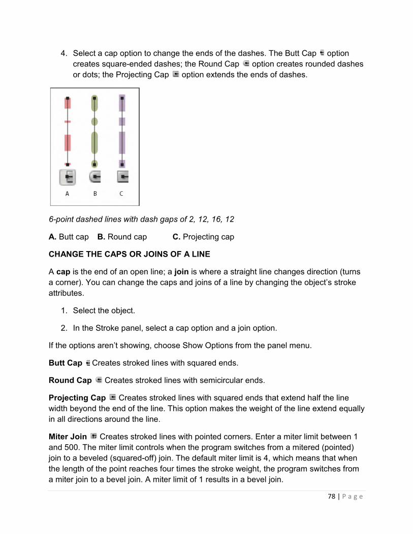
78 | P a g e
4. Select a cap option to change the ends of the dashes. The Butt Cap option
creates square-ended dashes; the Round Cap option creates rounded dashes
or dots; the Projecting Cap option extends the ends of dashes.
6-point dashed lines with dash gaps of 2, 12, 16, 12
A. Butt cap B. Round cap C. Projecting cap
CHANGE THE CAPS OR JOINS OF A LINE
A cap is the end of an open line; a join is where a straight line changes direction (turns
a corner). You can change the caps and joins of a line by changing the object’s stroke
attributes.
1. Select the object.
2. In the Stroke panel, select a cap option and a join option.
If the options aren’t showing, choose Show Options from the panel menu.
Butt Cap Creates stroked lines with squared ends.
Round Cap Creates stroked lines with semicircular ends.
Projecting Cap Creates stroked lines with squared ends that extend half the line
width beyond the end of the line. This option makes the weight of the line extend equally
in all directions around the line.
Miter Join Creates stroked lines with pointed corners. Enter a miter limit between 1
and 500. The miter limit controls when the program switches from a mitered (pointed)
join to a beveled (squared-off) join. The default miter limit is 4, which means that when
the length of the point reaches four times the stroke weight, the program switches from
a miter join to a bevel join. A miter limit of 1 results in a bevel join.
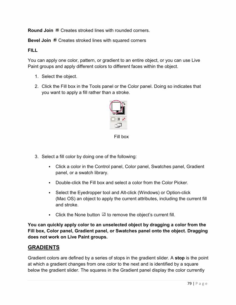
79 | P a g e
Round Join Creates stroked lines with rounded corners.
Bevel Join Creates stroked lines with squared corners
FILL
You can apply one color, pattern, or gradient to an entire object, or you can use Live
Paint groups and apply different colors to different faces within the object.
1. Select the object.
2. Click the Fill box in the Tools panel or the Color panel. Doing so indicates that
you want to apply a fill rather than a stroke.
Fill box
3. Select a fill color by doing one of the following:
� Click a color in the Control panel, Color panel, Swatches panel, Gradient
panel, or a swatch library.
� Double-click the Fill box and select a color from the Color Picker.
� Select the Eyedropper tool and Alt-click (Windows) or Option-click
(Mac OS) an object to apply the current attributes, including the current fill
and stroke.
� Click the None button to remove the object’s current fill.
You can quickly apply color to an unselected object by dragging a color from the
Fill box, Color panel, Gradient panel, or Swatches panel onto the object. Dragging
does not work on Live Paint groups.
GRADIENTS
Gradient colors are defined by a series of stops in the gradient slider. A stop is the point
at which a gradient changes from one color to the next and is identified by a square
below the gradient slider. The squares in the Gradient panel display the color currently

80 | P a g e
assigned to each gradient stop. With a radial gradient, the leftmost gradient slider
defines the center point’s color fill, which radiates outward to the color of the rightmost
gradient slider.
1. Do one of the following:
� To create a new gradient, deselect all objects and click the gradient box at
the bottom of the Tools panel.
� To modify an object’s gradient, select the object.
� To modify a preset gradient, click a gradient swatch in the Swatches
panel.
To display only gradients in the Swatches panel, click the Show
Swatch Kinds button and choose Show Gradient Swatches.
In the Gradient panel, select a gradient type (Linear or Radial).
If you select Linear, enter an angle of direction for the gradient in the Angle text box. Or,
drag the Gradient tool in the document window to set the angle.
Select colors for the gradient:
� To define the starting and ending colors of a gradient, click the leftmost or
rightmost gradient stop. Specify a color in the Color panel, or Alt-click
(Windows) or Option-click (Mac OS) a color swatch in the Swatches panel.
Or, drag a color from the Color panel or the Swatches panel onto the
gradient stop.
Note: If you create a gradient between spot colors, you must deselect Convert To
Process in the Separation Setup dialog box to print the gradient in individual spot color
separations.
� To add intermediate colors to a gradient, drag a color from the Swatches
panel or the Color panel onto the gradient slider. Or, click anywhere below
the gradient slider, and then select a color as you would for the starting or
ending color. To delete an intermediate color, drag the square off the
gradient slider.
� To adjust the midpoints of the gradient’s color stops (the point at which
two color stops are 50%), drag a diamond icon located above the slider or
select the icon and enter a value between 0 and 100 in the Location text
box.

81 | P a g e
� To adjust the endpoints of the gradient’s color stops, drag the leftmost or
rightmost gradient stop below the gradient slider.
Click the New Swatch button in the Swatches panel to save the new or modified
gradient as a swatch. Or, drag the gradient from the Gradient panel or Tools panel to
the Swatches panel
Why Vectors?
Once upon a time, people had to use pen and paper to compose letters or write articles.
College papers were drafted on stacks of notebook paper; lots of lines crossed out
unwanted words or sentences, while little carets inserted additional words or phrases. It
wasn’t unusual to see garbage cans full of crumpled pieces of paper (this was also
before recycling), or for writers to mark pages with arrows or footnotes that pointed to
other places where they wanted to insert another paragraph or two.
In contrast, I am writing this article while sitting in front of a screen, my fingers on a
keyboard. If I decide I don’t like something, I move my hand over to the mouse, highlight
the offending text, and with a simple click of a button, delete it. As I read over what I’ve
written, I decide a clarifying remark would be in order, so I move my cursor up and type
in my new thought.
Learning how to create and use vector graphics is as powerful as learning how to use a
word-processing program.
What Are Vector Graphics?
Most images that you see on a Website are raster graphics — images made up of little
dots (pixels) of color. If you were to take a gif or jpeg and zoom in, you’d see the
individual pixels that make up the graphic:
If you use an imaging program to shrink the graphic, it makes some calculations that
"average" neighboring pixels together to create an image with smaller dimensions. But if

82 | P a g e
you wanted to enlarge the graphic, the imaging program would take the existing pixels,
perform some calculations, and add in lots of extra pixels to make the image larger. This
usually results in a blurry picture. In the diagram below, you can see our original
100×102 pixel image, enlarged 300%. Raster images do not enlarge well!
Time to contrast raster graphics with vector graphics: Vector graphics are made up of
points that define lines and curves. For example, the rectangle below is a vector graphic
made up of four points connected by lines, and the abstract shape is made up of points
connected by curved lines. The graphics hold information about the direction of the line
or curve, how thick the line is, and what color or pattern fills the shape.
The great thing about vector graphics is that, because you’re only dealing with points
and lines, you can enlarge them quite easily without any loss of detail. This makes
vector graphics great for logos and diagrams that might need to be output at different
sizes. For example, when designing a logo, I’ll often use a vector graphics program to
make the initial file, and then create a raster version for an optimized, Web-ready file.
Another good thing about vector graphics is that their file size is usually smaller. Raster
graphics have to store information about each pixel. Vector graphics only have to store
information about the points.
By now, you should be pretty excited about vector graphics. Let’s start to make them!
Basic Shapes
Adobe Illustrator and Macromedia Freehand have many basic shape tools that make it
easy to create rectangles, circles, and other shapes. Let’s take a quick tour of the Tools

83 | P a g e
palettes (palettes may vary slightly depending on what version of the program you
have):
Both Illustrator and Freehand display the Ellipse and Rectangle Tools by default:
Illustrator:
Freehand:
In Illustrator, hold down the ellipse and rectangle buttons to view more tools for other
types of shapes — polygons, spirals, and rounded rectangles.
Illustrator tools:
Freehand has an additional Polygon tool under the Rectangle Tool option, as well as
the Arc Tool and Spiral Tool, accessible from the Xtra Tools Palette (Window > Toolbars
> Xtra Tools). To create rounded rectangles or star shapes, you can modify some of the
options of the tools or objects (more about this later).
Freehand tools:
Drawing a shape using one of these shape tools is really, really easy.
1. Select the tool.
2. Click in the document, hold, and drag.
3. Release the mouse button when the shape is as big as you want it to be. You’re
done!

84 | P a g e
The polygon and spiral tools will always draw from the center; that is, the place you
initially click will be the center starting point of the object. The rectangle and ellipse tools
will, by default, draw from the top-left corner. If you want rectangles and ellipses drawn
from the center, hold the Alt (PC) or Option (Mac) key while you draw. This tip works for
both Illustrator and Freehand.
Default draws from corner
Holding alt or option key draws from center.
Changing Options or Properties of Basic Shapes
Illustrator: When using the shape tools in Illustrator, you may select the tool and then
simply click once on the page (don’t hold and drag) to pull up the options dialog box for
that shape. The options dialog box allows you to define specific dimensions for a shape
(for example, a precise 2×3-inch rectangle, or a 200×200-pixel circle) and, for some
shapes, to provide additional options. For example, the Rounded Rectangle Tool option
box allows you to specify the radius for the rounded corners:
Similarly, the Polygon (and Star) Tools have options that allow you to define the number
of sides (or points) the shape will have:

85 | P a g e
After you define the options, click "OK" to create a shape with those specifications. The
shape tool will remember the options for other shapes that you create with that tool. To
change them, simply click once to bring up the options dialog box again.
Freehand: Freehand’s shape options can be accessed by double-clicking on the tool
button itself, which, in the case of the Rectangle Tool, allows you to specify a corner
radius to create a rounded rectangle:
Double-click the polygon tool, and you’ll be able to specify the number of sides —
whether the shape is a polygon or a star — and even the angles of the star points.
After you create a shape in Freehand, you can further refine its dimensions and
properties by selecting the shape and changing the numbers and options in the
Properties > Object palette.

86 | P a g e
If exact dimensions don’t matter to you, but you want to enlarge or shrink an object in
Illustrator or Freehand, switch to the black arrow tool (known as "Selection Tool" in
Illustrator, "Pointer Tool" in Freehand, and "black arrow" for us low-tech types), then
select the object, and finally drag on the corner handles to get the object to your ideal
size.
Working with Paths and the Pen Tool
Becoming comfortable with the Pen Tool often takes a while for vector graphic newbies.
Unlike pencil-and-paper doodling (or comparatively, using a pencil- or brush-type tool in
a typical drawing program), where your hand (or mouse) guides the drawn path, the pen
tool creates shapes based on a series of points and their corresponding "direction lines"
(Illustrator term) or "handles" (Freehand term).
Drawing a complex shape with a pencil or brush tool usually involves clicking once to
start the shape, then holding the mouse button down, and dragging the mouse to follow
the lines of the shape. Drawing the same shape with a pen tool involves a series of
clicks and drags to set the anchor points and define curve directions. It sounds
complicated, but once you get the hang of it, you’ll never look back!
Select the Pen Tool, and go for it:
Illustrator:
Freehand:
Click once on the document, then move the cursor and click again. This creates a line
that connects the two points.
By clicking again, you can start to create a shape:

87 | P a g e
To "close" the path to actually make a shape, move the cursor to the original point.
When the cursor turns to a pen shape with a small circle, click on the point and the
shape will be closed off. If the cursor doesn’t change, it means that you aren’t quite on
top of the original point, so you’ll end up just creating another point without closing the
shape.
What you’ve learned so far:
1. Clicking with the pen tool creates corner points.
2. Each new click creates a connected line segment with the previous point.
3. Bringing the cursor back to the original point and clicking will close the path to
create a shape.
Now, let’s move on to curves.
With the same Pen Tool, click once to create a starting "corner" point. Then, click again
— but this time, hold the mouse down and drag. A curve will form. You can continue to
hold and drag in different directions to see how the curve is affected. The resulting
tangent line can be referred to as a "direction line" or a "handle."
The location at which you place the next point will affect the shape of the resulting
curve, as you can see in the examples below:

88 | P a g e
The black arrow tool selects the entire path (so that you can move it around and resize
it). Use the "white arrow tool" (known as the Direct Selection Tool in Illustrator and the
Subselect Tool in Freehand) to tweak individual points and direction lines.
Illustrator:
Freehand:
With the white arrow tool, select the point on the curve that you wish to tweak:
Now, grab one of the direction line handles and pull. You’ll see the curves adjust; the
entire curve shifts so that the direction line remains tangent to the curve. The side of the
curve that you’re pulling grows more pronounced the further out you drag the handle.
In another example, you can see how pulling out both handles makes the curve "wider."

89 | P a g e
The white arrow tool can also be used to move individual points around:
Now you also know how to:
1. Use the pen tool to create curved points (by clicking and dragging).
2. Use the white arrow tool to tweak points and direction lines.
But there are many more ways that you can work with paths
A Whirlwind Tour of Other Path Tools
You may add points to an existing path. In both Illustrator and Freehand, first select the
path that you want to add points to, then hover over the path with the pen tool. You’ll
see the cursor change to a pen with a plus (+) sign. Click once and a new point will be
added, with direction handles that follow the existing curve. (Illustrator also has the "Add
Anchor Point Tool," hidden behind the Pen Tool, which does the same thing but doesn’t
require you to select a path first.)
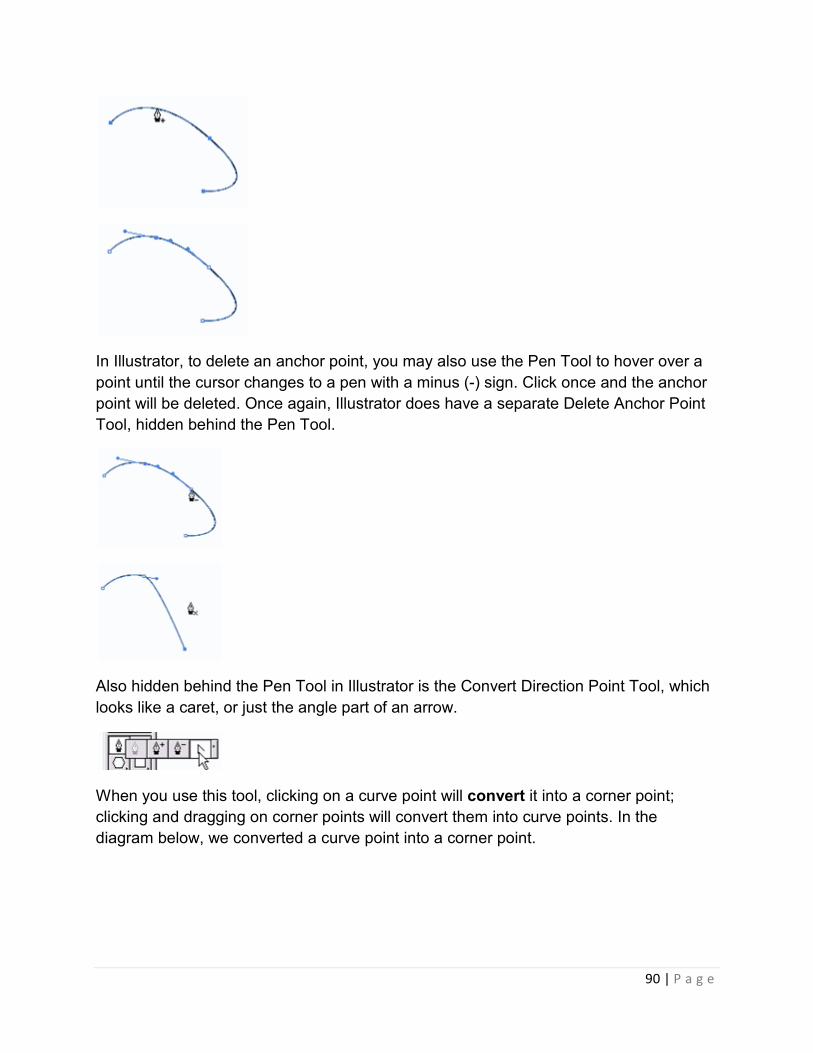
90 | P a g e
In Illustrator, to delete an anchor point, you may also use the Pen Tool to hover over a
point until the cursor changes to a pen with a minus (-) sign. Click once and the anchor
point will be deleted. Once again, Illustrator does have a separate Delete Anchor Point
Tool, hidden behind the Pen Tool.
Also hidden behind the Pen Tool in Illustrator is the Convert Direction Point Tool, which
looks like a caret, or just the angle part of an arrow.
When you use this tool, clicking on a curve point will convert it into a corner point;
clicking and dragging on corner points will convert them into curve points. In the
diagram below, we converted a curve point into a corner point.
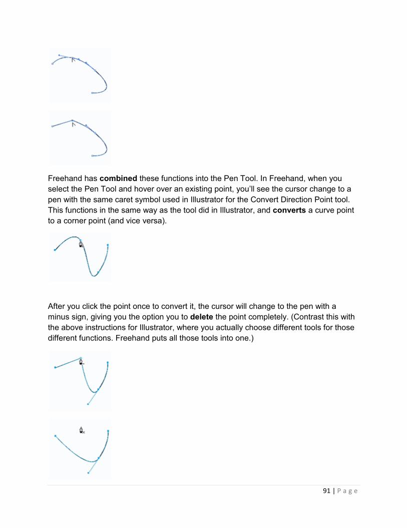
91 | P a g e
Freehand has combined these functions into the Pen Tool. In Freehand, when you
select the Pen Tool and hover over an existing point, you’ll see the cursor change to a
pen with the same caret symbol used in Illustrator for the Convert Direction Point tool.
This functions in the same way as the tool did in Illustrator, and converts a curve point
to a corner point (and vice versa).
After you click the point once to convert it, the cursor will change to the pen with a
minus sign, giving you the option you to delete the point completely. (Contrast this with
the above instructions for Illustrator, where you actually choose different tools for those
different functions. Freehand puts all those tools into one.)
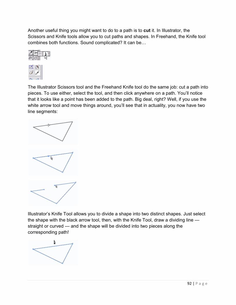
92 | P a g e
Another useful thing you might want to do to a path is to cut it. In Illustrator, the
Scissors and Knife tools allow you to cut paths and shapes. In Freehand, the Knife tool
combines both functions. Sound complicated? It can beY
The Illustrator Scissors tool and the Freehand Knife tool do the same job: cut a path into
pieces. To use either, select the tool, and then click anywhere on a path. You’ll notice
that it looks like a point has been added to the path. Big deal, right? Well, if you use the
white arrow tool and move things around, you’ll see that in actuality, you now have two
line segments:
Illustrator’s Knife Tool allows you to divide a shape into two distinct shapes. Just select
the shape with the black arrow tool, then, with the Knife Tool, draw a dividing line —
straight or curved — and the shape will be divided into two pieces along the
corresponding path!

93 | P a g e
To achieve this same functionality in Freehand, double-click on the Knife tool to get to
the options, and check the "Close cut paths" option.
They’re the basics of manipulating paths. In the next section, we’ll take you step-by-step
through an easy, practical example where you can apply all your new knowledge… and
even learn a few more tricks along the way!
Easy Logos Using Paths
Let’s say that you work for Gateway, and you need to duplicate the Gateway "spotted-g"
logo:
Gateway and the Spotted G Gateway logo are trademarks of Gateway, Inc. We’ve used
them here for the purposes of illustration only – no infringement of the trademark is
intended.
With Illustrator or Freehand, this will be quite a snap!
First, use the Pen Tool to create the basic shape.

94 | P a g e
The shape is obviously not quite perfect, so we’ll use the white arrow tool to tweak the
lines and points…
Note: there are a number of additional steps the perfectionist could have taken to get a
perfectly even curved-triangle shape. For example, you could have created a 3-sided
triangle with the polygon tool first and used the Convert Direction Tool to "curve" the
points. In Freehand, you could have skipped this step by modifying the Object
Properties of a triangle to have curved corners. Then, you could have used the Pen
Tool — or Add Anchor Points Tool — to add three more points on the sides of the now-
curved triangle. These points could be moved "inward" by hand, or by using the white
arrow tool to select only those three side points, then using the Scale tool to move them
towards the center. Perhaps you may want to try this process; for the purposes of this
educational tutorial, doing things freehand — no pun intended — is fine.
Now, use the Ellipse Tool to create a circle. Here’s another tip: to make a perfect circle
or square, hold the Shift key down while you draw. Holding the shift key generally

95 | P a g e
"constrains" movements in most graphics programs. We also held down the Alt key
(Mac — Option key) to draw the circle from the center, instead of the corner.
Create another circle, centered inside the first.
Note: There are plenty of ways that you can create two circles within each other. In
Illustrator, one way is to draw two circles, then click on the center of one of the circles
and move it over the center of the other circles. You’ll notice that the top circle "snaps"
to the middle of the other circle when you get close enough. This method works for
other polygons that have "centers." Another way that works in both Illustrator and
Freehand is to select the two circles, then use the Align Palette to line up the centers.
Yet another way is to draw the first circle, select it, and switch to the Scale tool. Hold the
Shift key — to keep it a perfect circle — then start dragging to make a smaller circle.
Hold down the Alt (PC) or Option (Mac) key while you’re dragging… then let go of the
mouse. Holding down the Alt/Option key makes a copy of the object, which is a useful
trick for other purposes.
Now, use the Rectangle Tool to make the long rectangular section of the logo.
With the basic shapes in place, we’ll first fill the curvy shape with black. In Illustrator,
select the shape, and in the Tools Palette, click the Color button to fill the shape with
color.

96 | P a g e
In Freehand, select the shape, then use the paint bucket color dropdown to fill the
shape with color.
You may also get rid of the outline (stroke). In Freehand, use the pencil dropdown
(above the paint bucket) to choose the "no color" option. In Illustrator, first click on the
Stroke icon (outlined box), then click the "no color" option.
At this point, hide the curvy shape by hitting Ctrl-3 (PC) or Command-3 (Mac) in
Illustrator, or going to View > Hide Selection in Freehand. This will allow us to work with
the other shapes without getting distracted.
Ok, it’s time to work with the other shapes: use the knife tool to cut the circle path just a
little above and below the rectangle.

97 | P a g e
Use the black arrow tool to select the cut segment and delete it.
Do the same to the other circle.
Now, use the pen tool to connect the endpoints of the shape.
Just to demonstrate that there are lots of ways you can do things, here’s another way to
achieve the same effect in Illustrator:
First, fill the larger circle with black (so that you can see it more easily).

98 | P a g e
Select both circles: use the black arrow tool and drag across the corner of the circles so
that both are selected. Open the Pathfinder palette in Illustrator. Choose the "Minus
Front" command. The two circles will be combined into one doughnut shape.
Now, use the Knife Tool to cut two lines across the ring shape slightly above and below
the rectangle.
Select the new cutout piece and hit Backspace to delete it.

99 | P a g e
Same effect; different method!
We’re almost there! Select both shapes and set the fill color to white.
Finally, unhide the curvy shape. In Illustrator, hit Ctrl-Alt-3 (PC) or Command-Option-3
(Mac). In Freehand, go to View > Show All. The black curvy shape will reappear, and
the logo is complete!
Summary
In this lengthy tutorial, you learned:
1. The difference between raster and vector graphics
2. How to make basic shapes in Illustrator and Freehand
3. How to resize shapes using the black arrow to select objects and drag on their
corner handles
4. How to use the pen tool to create corner points (by clicking)
5. That each new click creates a connected line segment with the previous point
6. That bringing the cursor back to the original point and clicking will close the path
to create a shape
7. How to use the pen tool to create curved points (by clicking and dragging)
8. How to use the white arrow tool to tweak points and direction lines

100 | P a g e
9. How to add, delete and convert points using the Pen Tool and its derivatives
10. How to use the Scissors and/or Knife Tools
11. How to use the Shift key to make perfect circles or squares
12. How to align two circles so that they’re centered
13. How to use the Alt key when moving objects to make copies of the object
14. How to change the fill and stroke colors of objects
15. How to "Hide" and "Unhide" objects


