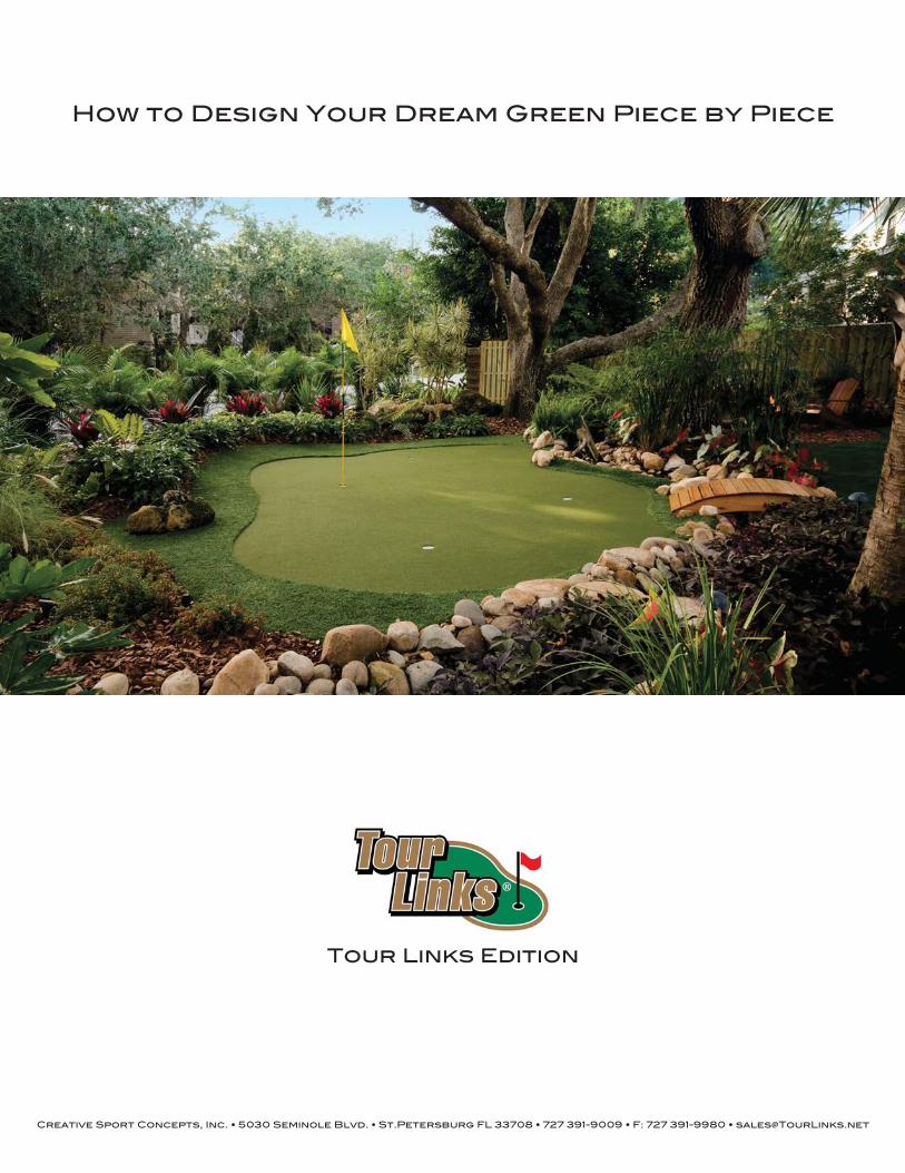
How to Design Your Dream Green Piece by Piece
Tour Links Edition
Creative Sport Concepts, Inc. • 5030 Seminole Blvd. • St.Petersburg FL 33708 • 727 391-9009 • F: 727 391-9980 • [email protected]

Choose your Design Sheet:
The size of your project will determine what size design sheet is needed. There are two design sheets: a 40 foot and a 61 foot. If your design is over 40 ft x 30 ft you will need to use the 61ft design sheet. On the 40 foot and 61 foot sheets, one box equals one panel.
NOTE: Blank design sheets and a design worksheet are on the last few pages of this document.
Identifying the Types of Panels Needed:
Figure 1.1 Identifies the different types of Tour Links® panels.
**A Tour Links filler plate can be placed in these panels if the use of a golf cup is not required.
Getting Started:
What you need to know about your project: • Your desired size • Shape • Number of holes • If a transition edge is needed • If it is an indoor or outdoor installation
Figure 1.2 Indicates that the Tour Links ICC panel can be rotated to position the
hole where it is needed.
Figure 1.3 Indicates that the Tour Links ICC panel can be rotated to position the
hole where it is needed.
IC--Inside Center Panel
The IC will be the majority of the panel area for most putting greens or landscaping projects. This panel is cut to shape to create any design profile desired.
ICC--Inside Center Panel with Cup Hole
The ICC is used in conjuction with the IC panel when a golf cup is required. The cup hole is positioned near the corner of the panel however the panel can be rotated which gives the designer four possible cup positions.
SE--Straight Edge Panel with Bump Rail
Used in the construction of greens and/or turf areas that require a straight raised edge boarder.
ORSCE--Outside Radius Single Curved Edge with Cup Hole and Bump Rail**
Used to create a 90 degree radiused corner. Also can be used to create a full circle for golf chipping station etc. This panel is able to accept a golf cup.
ORDCE--Outside Radius Double Curved Edge with Cup Hole and Bump Rail**
This panel creates a 90 degree corner with a bit more styling and also has indentations to store two golf balls and a logo sticker. This panel is able to accept a golf cup.
IRSCE--Inside Radius Single Curve Edge with Bump Rail
This panel is used to create inside radius turns.
2
ICC Panel
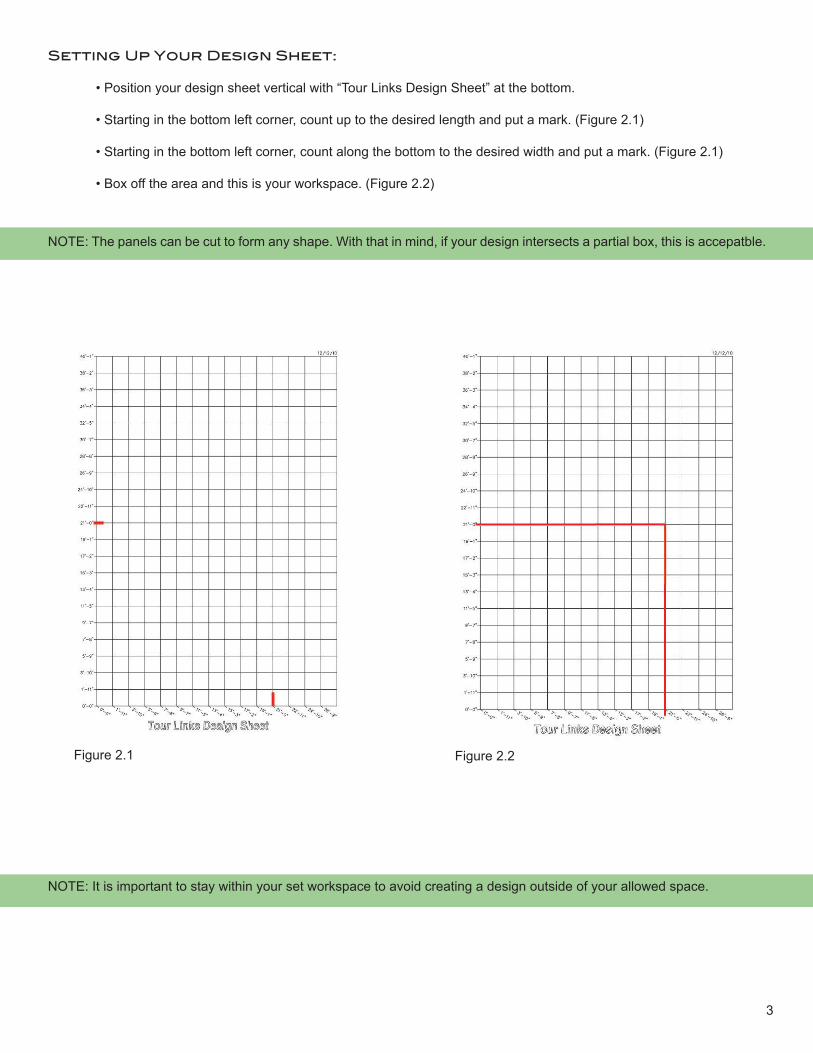
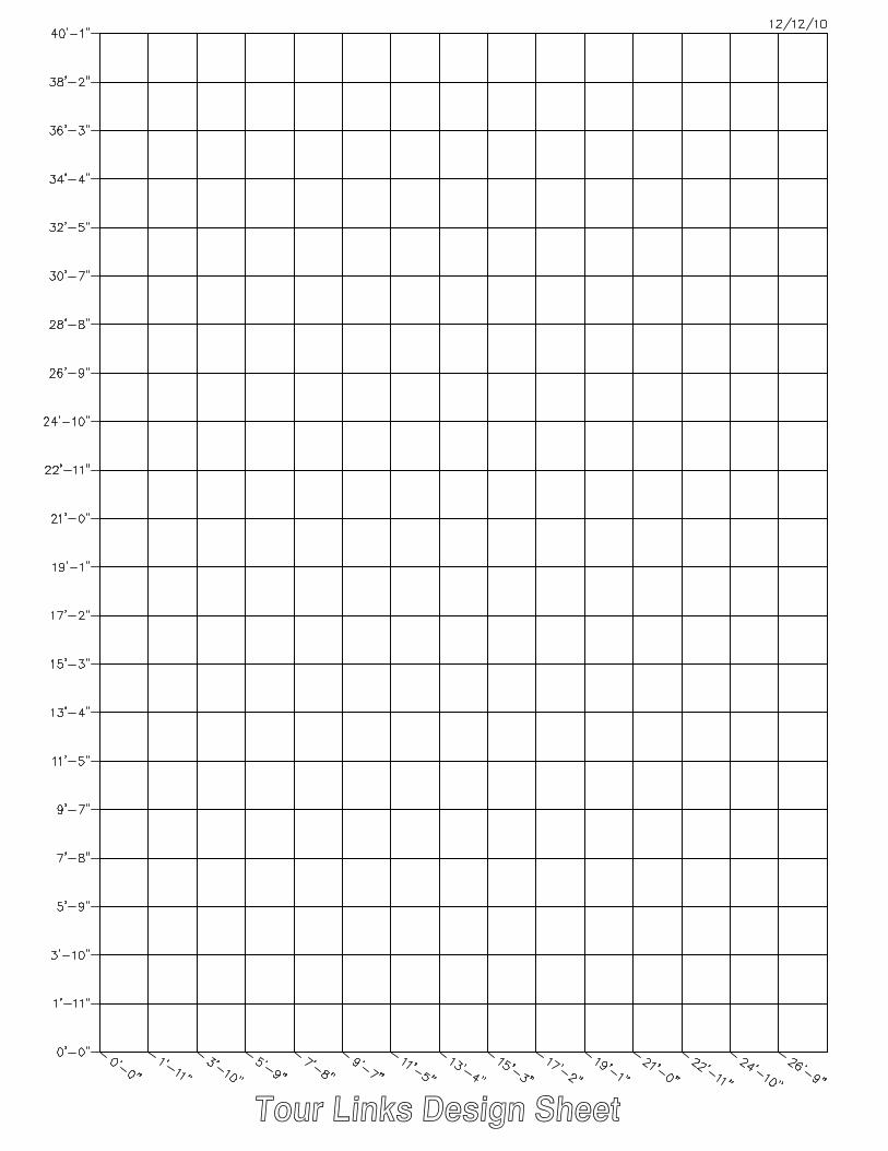
Setting Up Your Design Sheet:
• Position your design sheet vertical with “Tour Links Design Sheet” at the bottom.
• Starting in the bottom left corner, count up to the desired length and put a mark. (Figure 2.1)
• Starting in the bottom left corner, count along the bottom to the desired width and put a mark. (Figure 2.1)
• Box off the area and this is your workspace. (Figure 2.2)
NOTE: It is important to stay within your set workspace to avoid creating a design outside of your allowed space.
Figure 2.1 Figure 2.2
NOTE: The panels can be cut to form any shape. With that in mind, if your design intersects a partial box, this is accepatble.
3
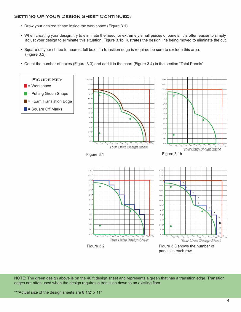
Setting Up Your Design Sheet Continued:
• Draw your desired shape inside the workspace (Figure 3.1).
• When creating your design, try to eliminate the need for extremely small pieces of panels. It is often easier to simply adjust your design to eliminate this situation. Figure 3.1b illustrates the design line being moved to eliminate the cut.
• Square off your shape to nearest full box. If a transition edge is required be sure to exclude this area. (Figure 3.2).
• Count the number of boxes (Figure 3.3) and add it in the chart (Figure 3.4) in the section “Total Panels”.
Figure 3.1
Figure 3.2 Figure 3.3 shows the number of panels in each row.
NOTE: The green design above is on the 40 ft design sheet and represents a green that has a transition edge. Transition edges are often used when the design requires a transition down to an existing floor.
***Actual size of the design sheets are 8 1/2” x 11”
= Workspace
= Putting Green Shape
= Foam Transistion Edge
= Square Off Marks
Figure Key
Figure 3.1b
4

Identifying the Number of Each Panel Needed:
• Count the total number of panels. Put that amount in the “total panel” box.
• Count each ICC, SE, ORSCE, ORDCE, and IRSCE panel then put the amount in the corresponding box.
• Count the panels that can be double cut, divide it by two, then put the amount in the box. (Figure 4.3)
• Calculate the difference between the “Total Panels” and the total number of ICC, SE, ORSCE, ORDCE, IRSEC and the number of double cuts. This will give you the total number of ICs needed.
Panel TotalTotal Panels 81IC 73ICC 3SE 0ORSCE 0ORDCE 0IRSCE 0Double Cut 5
Figure 3.4
Double Cuts:
Double cutting the panel is key to material and cost savings. A general rule is, if the edge of your green cuts through less than half of the panel, that panel can reused and cut again. See Figures 4.1 and 4.2
Figure 4.1Can be Double cut
Figure 4.2Can be double cut if a small
corner piece is required.
Figure 4.3“X” stands for panels that can be double cut.
In this figure 10 panels can be double cut.10 divded by two equals five. Only five panels are required.
Key1st Cut
2nd Cut
Scrap
5

More Examples of Putting Green Designs:
The scenario below illustrates a 28.6’ x 21’ putting green that uses bump rails and has five holes and putting turf only.
Panel TotalTotal Panels 147IC 97ICC 6SE 36ORSCE 5ORDCE 1IRSCE 2Double Cut 0
6
ORDCE
IC
ICC
ORSCE
SE
IRSCE
Putting Turf

More Examples of Putting Green Designs:
The scenario below illustrates a 32’ x 23’ putting green that requires custom cutting of the IC panels and has three holes and incorporates fringe turf.
Panel TotalTotal Panels 158IC 155ICC 3SE 0ORSCE 0ORDCE 0IRSCE 0Double Cut 9
In this example 18 panels can be double cut.18 divded by two equals nine. Only nine panels are required.
7
Putting Turf 18” FringeFor a wrap and roll edge be sure to allow enough fringe to wrap over the panel edge and bury into the ground.

Tour Links Design Possibilites:
IC Center Panel Cut Green with Fringe and Transition Edge
Bump Rail Green No Fringe
IC Center Panel Cut Green with Fringe (No Transition Edge)
Bump Rail Green with Fringe
8
Putting Turf
Fringe
Transition Edge
Putting Turf
Fringe
Putting Turf
FringePutting Turf
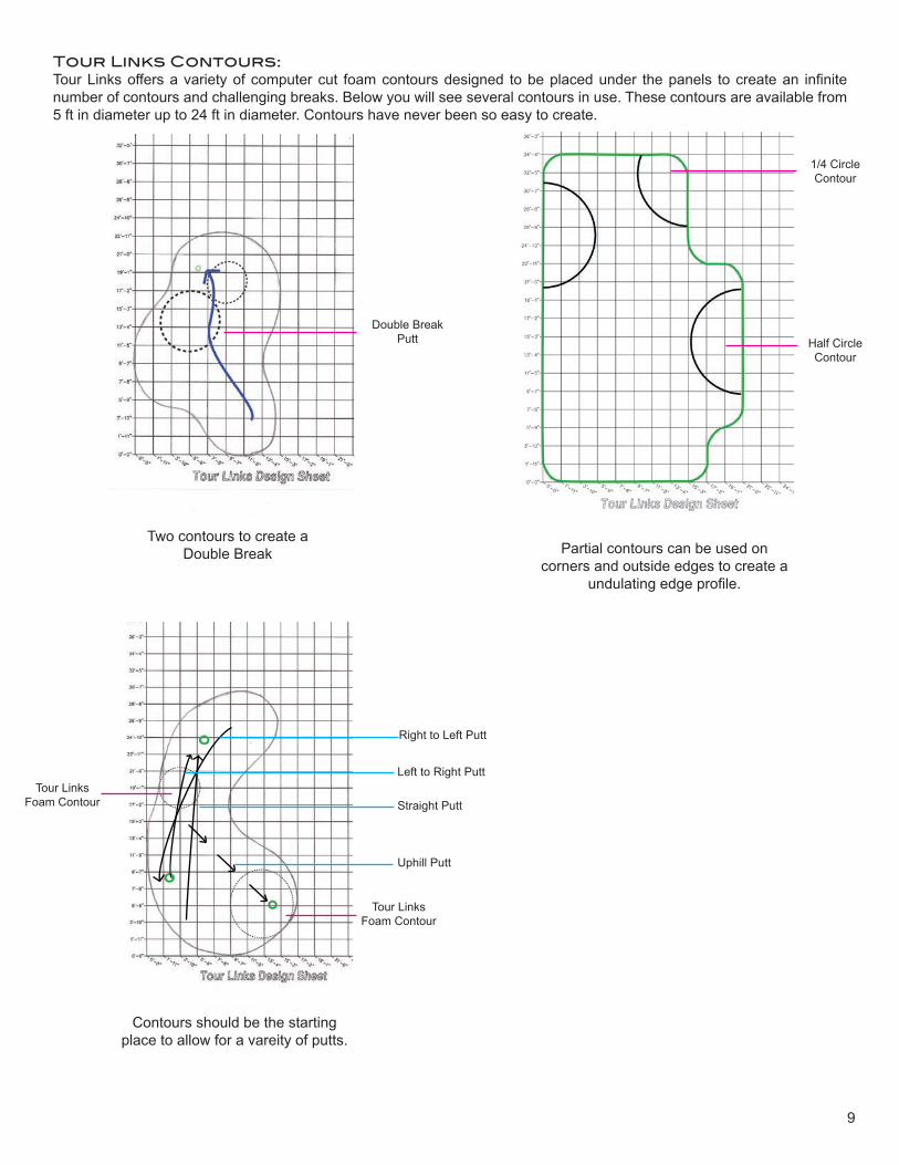
Tour Links Contours: Tour Links offers a variety of computer cut foam contours designed to be placed under the panels to create an infinite number of contours and challenging breaks. Below you will see several contours in use. These contours are available from 5 ft in diameter up to 24 ft in diameter. Contours have never been so easy to create.
Half Circle Contour
1/4 Circle Contour
Double BreakPutt
Tour Links Foam Contour
Tour Links Foam Contour
Two contours to create a Double Break Partial contours can be used on
corners and outside edges to create a undulating edge profile.
Contours should be the starting place to allow for a vareity of putts.
9
Right to Left Putt
Left to Right Putt
Straight Putt
Uphill Putt
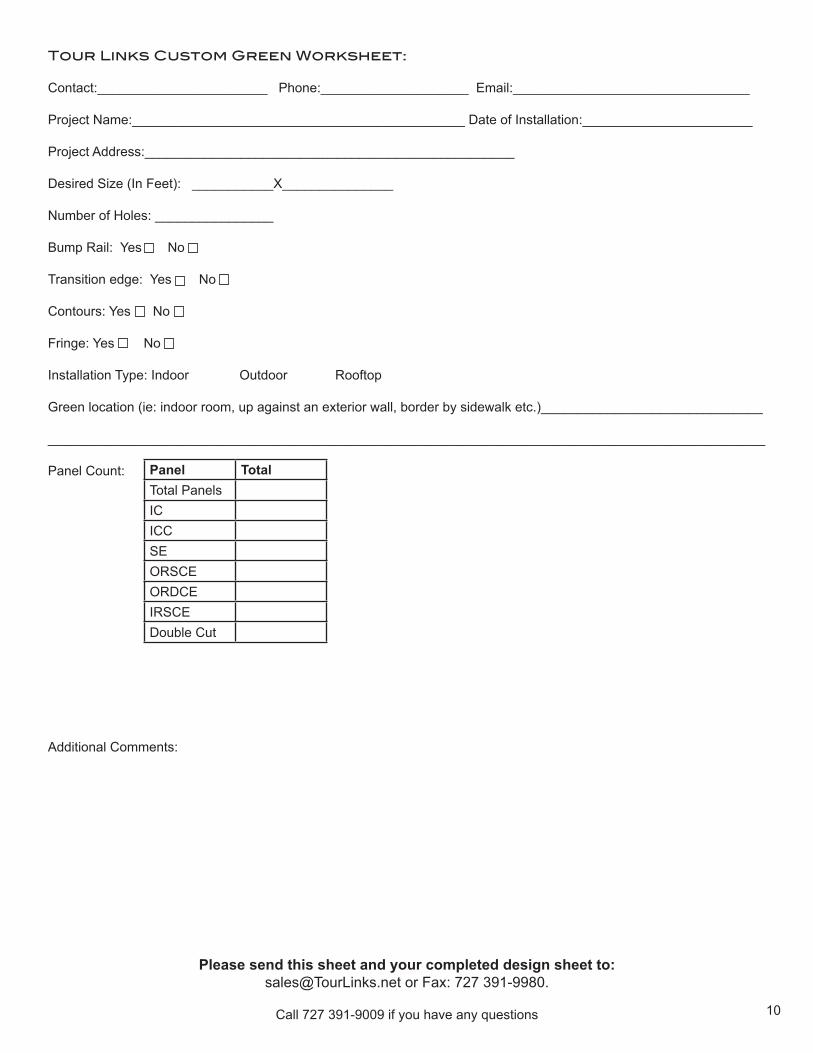
Tour Links Custom Green Worksheet:
Contact:_______________________ Phone:____________________ Email:________________________________
Project Name:_____________________________________________ Date of Installation:_______________________
Project Address:__________________________________________________
Desired Size (In Feet): ___________X_______________
Number of Holes: ________________
Bump Rail: Yes No
Transition edge: Yes No
Contours: Yes No
Fringe: Yes No
Installation Type: Indoor Outdoor Rooftop
Green location (ie: indoor room, up against an exterior wall, border by sidewalk etc.)______________________________
_________________________________________________________________________________________________ Panel Count: Panel Total
Total PanelsICICCSEORSCEORDCEIRSCEDouble Cut
Additional Comments:
Please send this sheet and your completed design sheet to:[email protected] or Fax: 727 391-9980.
Call 727 391-9009 if you have any questions 10