Accepted Manuscript
Highly Porous Organic-Inorganic Hybrid Fiber from Copolymers of Styrene
and Polyhedral Oligomeric Silsesquioxane-Derived Methacrylate: Syntheses,
Fiber Formation and Potential Modification
Thanarath Pisuchpen, Varol Intasanta, Voravee P. Hoven
PII: S0014-3057(14)00293-6
DOI: http://dx.doi.org/10.1016/j.eurpolymj.2014.08.017
Reference: EPJ 6545
To appear in: European Polymer Journal
Received Date: 4 May 2014
Revised Date: 6 August 2014
Accepted Date: 13 August 2014
Please cite this article as: Pisuchpen, T., Intasanta, V., Hoven, V.P., Highly Porous Organic-Inorganic Hybrid Fiber
from Copolymers of Styrene and Polyhedral Oligomeric Silsesquioxane-Derived Methacrylate: Syntheses, Fiber
Formation and Potential Modification, European Polymer Journal (2014), doi: http://dx.doi.org/10.1016/
j.eurpolymj.2014.08.017
This is a PDF file of an unedited manuscript that has been accepted for publication. As a service to our customers
we are providing this early version of the manuscript. The manuscript will undergo copyediting, typesetting, and
review of the resulting proof before it is published in its final form. Please note that during the production process
errors may be discovered which could affect the content, and all legal disclaimers that apply to the journal pertain.

1
Highly Porous Organic-Inorganic Hybrid Fiber from Copolymers of
Styrene and Polyhedral Oligomeric Silsesquioxane-Derived
Methacrylate: Syntheses, Fiber Formation and Potential
Modification
Thanarath Pisuchpena,b
, Varol Intasantac, Voravee P. Hoven
a*
aOrganic Synthesis Research Unit, Department of Chemistry, Faculty of Science, Chulalongkorn
University, Phayathai Road, Pathumwan, Bangkok 10330, Thailand
bCenter of Excellence on Petrochemical and Materials Technology, Chulalongkorn University,
Phayathai Road, Pathumwan, Bangkok 10330, Thailand
cNational Nanotechnology Center, National Science and Technology Development Agency,
Thailand Science Park, Phahonyothin Road, Klong Luang, Pathumthani, 12120, Thailand
Correspondence to: Voravee P. Hoven (E-mail: [email protected])
Abstract
Copolymers comprising styrene and polyhedral oligomeric silsesquioxane-derived methacrylate
(PS-co-PMAPOSS) of various MAPOSS:styrene ratios with Mn over 100 kDa were prepared by
concurrent ARGET ATRP-RAFT. Fibrous mats of the synthesized copolymers are then
fabricated through electrospinning process using various conditions (solvents and POSS
content). The results from SEM and EDS analysis unveiled the fibers’ physical and chemical
characteristics as a clear footprint of the influence of solvent selection (tetrahydrofuran (THF)
and dimethylformamide (DMF)). It is evident that liquid-liquid phase separation followed by
phase segregation of PS and POSS constitute to the varying degree of porosity in the electrospun
fibers. Finally, preliminary tests suggest that highly porous PS-co-PMAPOSS fiber can be
modified with high temperature, plasma and silanization for further novel applications.
Keywords: porous fibers; electrospinning; polystyrene; POSS; phase separation
2
1. Introduction
Porous materials represent a class of functional constituents in catalysis, filtration, storage,
control release, sensing, insulation and absorption. Fabrications of such structures can be
accomplished by a number of approaches. Phase separation among incompatible components at
small length scale, in particular, epitomizes one of the effective ways that help creating porosity.
Recent advances in molecular design and polymer syntheses have made possible hybridization of
not only organic and inorganic components, but also those with definite incompatibilities, into
one single polymeric chain. Through which, structural development driven by phase separation
could be tuned via the degree of incompatibilities among the choices of monomers during
syntheses and solvent combination in the course of fabrications.
Polyhedral oligomeric silsesquioxane (POSS) is an organic-inorganic hybrid compound, of
which the most well-known is that of cubic structure, also known as T8. Due to its chemical
similarity to silica, POSS is sometimes referred to as the smallest colloidal silica. Thermal and
chemical stability of POSS, as well as various functionalities can convey great potential in the
area of polymer nanocomposites.
Various routes have been developed as means to assimilate POSS functional moieties into
polymer matrix, including melt blending [1], solution blending [2] and addition of POSS to
polymer chains either through grafting [3] or copolymerization [4]. In addition to the mechanical
and thermal integrity, such incorporation of POSS molecules can affect morphological and
structural feature of the polymer itself. Polymerized POSS molecules are known to form
segregated nanosized semi-crystalline or crystalline domains, even if the functional groups on
main chains and POSS subunits are similar [5]. Random copolymers with POSS on their chains
have revealed lamellar-like POSS aggregates [6], while block copolymers containing POSS have
exhibited long-range ordered lamellar or cylindrical structures [7].
Electrospinning becomes a prevalent and versatile technique to fabricate precursor polymer
solutions or melt into non-woven fibrous mat under electric-field induced repulsive coulombic
force. With sufficiently entangled polymeric networks as spinning precursor, various inorganic
materials can also be fabricated into ultrafine fibers [8-10]. Its simplicity and ability to induce
unique micro- and nanostructures bring about innumerable possibilities of applications, including
POSS-derived nanocomposites, in which electrospinning facilitates dispersion of nanoparticles
[11,12]. As Cozza and co-workers had demonstrated, electrospinning could also be used to
3
promote dispersion and prevent aggregation of POSS in cellulose acetate matrix [13].
Morphological features of electrospun fibers have also been shown to be affected by an addition
of POSS. In publication of Xue and co-workers, electrospun fibers from copolymers of
poly(methyl methacrylate) (PMMA) containing POSS exhibited nanofibrillar structures of
ordered POSS moieties which were also longitudinally aligned in the fiber direction [14].
Herein this research, we propose an approach to generate highly porous organic-inorganic
hybrid fibrous materials via chemical design, polymer syntheses, fiber formation and interplay
among solubilities and domain separation. Specifically, we would like to explore an impact of
POSS incorporation on the morphological and structural feature of polystyrene (PS) through the
dynamics of electrospining as means for fiber formation. Commercially available methacrylate-
substituted POSS, heptaisobutyl-(1-propylmethacrylate)-POSS (MAPOSS) was copolymerized
with styrene employing a controlled radical polymerization method denoted as concurrent
RAFT-ARGET ATRP (Scheme 1). With subsequent fabrication by electrospinning lined ahead,
the initial challenge was to attain copolymers with molecular weight high enough for sufficient
molecular entanglement suitable for electrospinning. This polymerization process is a
combination of Reversible Addition-Fragmentation Chain Transfer (RAFT) and Activator
Regenerated by Electron Transfer for Atom Transfer Radical Polymerization (ARGET ATRP).
Unlike conventional RAFT, which requires external source of radical, atom transfer process
provides a more consistent level of radical which is under influence of both ATRP and RAFT
equilibria. This novel approach provides a superior control over both initiation and propagation
and, as demonstrated by Matyjaszewski and coworkers, allows for narrow PDI for polymeric
chains with molecular weight even over 100 kDa [15-17]. The use of ARGET ATRP further
provides an additional simplicity to the reaction process and copolymer purification, especially
in this case where economical reducing agent like copper wire was employed. Subsequently,
fibers from the synthesized copolymers were then fabricated by electrospinning, in which several
parameters such as copolymer concentration and solvent composition were systematically
investigated.

4
S
S CN
COOH
4-cyano-4-(thiobenzoylthio)pentanoic acid
RSiO
O
O SiR
O
OSiR
O
ORSi
SiRO
SiRSi
RSi
O OOO
O O
N
NNCu(0)
CuBr2
CN
HOOC S
S
RSiO
O
O SiR
O
OSiR
O
ORSi
SiRO
SiRSi
RSi
O OOO
O O
PMDETA
styrene
MAPOSS
PS-co-PMAPOSS
n m
R =
Scheme 1. Synthesis of PS-co-PMAPOSS by concurrent RAFT-ARGET ATRP.
2. Experimental
2.1. Materials
Styrene (Sty) and copper (II) bromide (CuBr2) were purchased from Fluka. Heptaisobutyl-(1-
propylmethacrylate)-POSS (MAPOSS), pentamethyl- diethylenetri-amine (PMEDTA), 4,4′-
azobis(4-cyanovaleric acid) (ACVA), cyanovaleric acid dithiobenzoate (CVADTB) and
aluminium oxide were purchased from Sigma-Aldrich. Toluene, tetrahydrofuran (THF), N,N-
dimethylformamide (DMF) and ethanol were purchased from Lab-scan. All reagents were AR
grade and used as received.
2.2. Synthesis of PS and PS-co-PMAPOSS using concurrent RAFT-ARGET ATRP
2 mg of CuBr2, 26 µL of PMDETA, 12 mg of CVADTB (molar ratio of 1:140:10), 4.8 g
copper wire and designated amount of Sty and MAPOSS were added into a 25 mL scintillation
vial, which was then sealed with rubber septum. Purged with nitrogen gas for 15 min, the
reaction was set to carry out under nitrogen atmosphere at 90°C for 24 h. The crude products
were first dissolved in THF, and then passed through a basic alumina column to remove residual
catalysts. The resulting clear and colorless solution was then precipitated in an excessive amount
of ethanol under vigorous stirring. The solid was then dried at room temperature under vacuum
overnight to obtain a final copolymer product.
5
2.3. Electrospinning
In the preparation of spinning precursor solutions, the synthesized (co)polymers were
dissolved in various solvents including toluene, THF and mixture of THF-DMF. Each of the as-
prepared solution was loaded into a syringe equipped with a syringe pump and attached to a 1.5
cm-long blunt tip needle. A high voltage supply connected the needle with a positive voltage
cable and a receiving aluminum foil with a ground one. A polymer solution was electrospun
onto the ground aluminum foil under voltage of 20 kV, 15 cm collecting distance and flow rates
of 6.5-8.5 mL/h. The resulting electrospun fiber mats were left to dry in ambience for 24 h prior
to characterization.
2.4. Chemical modification
To test the tolerance to modification of the electrospun fibers, several procedures were carried
out. First, tetraethoxysilane (TEOS) (5% of polymer weight) was added to polymer solution prior
to electrospinning. Next, silanol groups were introduced to surface of the electrospun fiber mats
through 2 methods, calcination at 400oC for 1 h and oxygen plasma treatment at 100 W for 10
min. Finally, electrospun fiber mats with silanol groups were treated with vapor phase of
trichloromethylsilane (MeSiCl3) following a published procedure [18]. Treated fiber mats were
characterized by a contact angle goniometer (Ramé-Hart, Model 200-F1, USA) for water contact
angle.
2.5. Nuclear magnetic resonance spectroscopy (NMR)
1H-NMR spectra was recorded in CDCl3 using Varian, model Mercury-400 nuclear magnetic
resonance spectrometer operating at 400 MHz. Chemical shifts (δ) were reported in part per
million (ppm) relative to the reference signals of tetramethylsilane (TMS) or the residual
protonated solvent.
2.6. Gel permeation chromatography (GPC)
Molecular weight and molecular weight distributions of the synthesized (co)polymers were
determined by gel permeation chromatography (GPC) using Water 600 controller and pump,
Waters E600 column connected to Waters 2140 refractive index detector, and THF as eluent.
The flow rate was 1 mL/min. PS standards were employed to construct a calibration curve.
6
2.7. Thermogravimetric analysis (TGA)
Thermal degradation behavior of all (co)polymer samples and percent ash were investigated
by thermogravimetric analysis (TGA) (Mettler Toledo, model TGA/SDTA 851, USA) over a
temperature range of 30-600 °C at a heating rate of 10 °C/min under ambient condition. The
data were analyzed with STARe SW program version 9.30.
2.8. Scanning electron microscopy (SEM) and energy dispersive x-Ray spectrometry (SEM-EDS)
The morphological appearances of the as-spun fibers were investigated using a scanning
electron microscope (SEM, JEOL, Model JSM-6480LV, Japan). Each sample was placed on the
holder with an adhesive tape and coated with a thin sputtered layer of gold. The scanning
electron images were obtained by using an acceleration voltage of 15 kV. The average fiber
diameter of the electrospun fibers was measured by Semafore software directly from SEM
images. Elemental analyses were performed under SEM model JSM-5800LV (JEOL, Japan)
under an EDS mode.
2.9. X-ray diffractometry (XRD)
The crystallinity of the synthesized (co)polymers and their respective as-spun fibers were
investigated using an X-ray diffractometer (model Rigaku TTRAX III, 18 kW, Japan). Each
sample was grounded into powder prior to analysis.
3. Results and discussion
3.1. Synthesis of PS and copolymers by concurrent RAFT - ARGET ATRP
For a polymer to be able to form fibers by itself via electrospinning, molecular weight of the
polymer has to be high enough to promote sufficient chain entanglement. To ensure
electrospinnability, this research aimed to synthesize PS-co-PMAPOSS with molecular weight
well above 100 kDa. A successful synthetic protocol of the copolymer with Mn (131.7 kDa)
reaching the expected target (130 kDa) employed 0.96 g of copper wire. As can be seen from
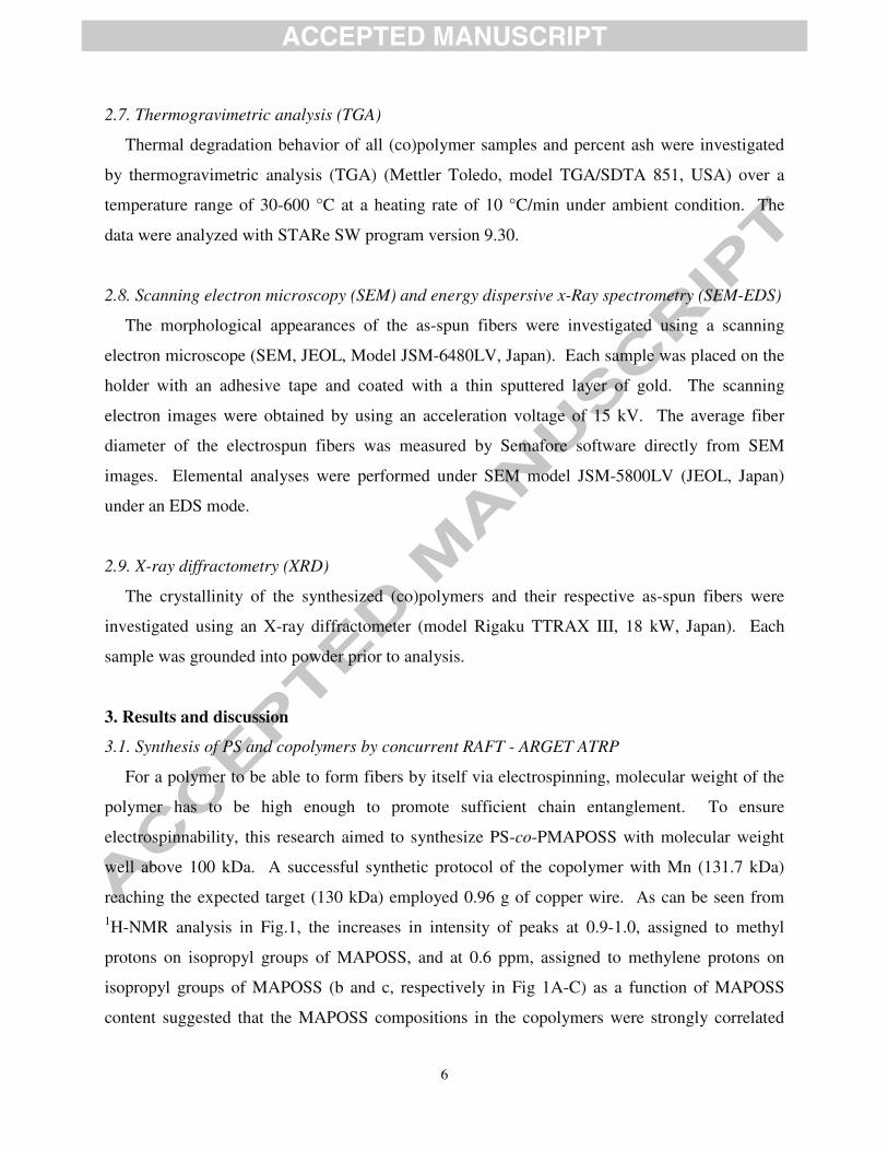
1H-NMR analysis in Fig.1, the increases in intensity of peaks at 0.9-1.0, assigned to methyl
protons on isopropyl groups of MAPOSS, and at 0.6 ppm, assigned to methylene protons on
isopropyl groups of MAPOSS (b and c, respectively in Fig 1A-C) as a function of MAPOSS
content suggested that the MAPOSS compositions in the copolymers were strongly correlated
7
with and proportional to those in the feed. Furthermore, there were no peaks in 5.5-6.0 ppm, a
range assigned to methylene protons of the monomers, indicating the absence of residual
unreacted monomers after purification. The weight percent of MAPOSS (%MAPOSS) in
copolymers was calculated from 1H NMR data using relative intensity of the peak at 0.6 ppm,
assigned to methylene protons on isopropyl groups of MAPOSS (b, Fig 1A-C), and that of the
peak at 6.2-7.2, assigned to phenyl protons on phenyl group of styrene (a, Fig 1A- C) (data
shown in Table 1). The %MAPOSS calculated from 1H-NMR, molecular weights of the
(co)polymers obtained from GPC analysis, and the thermal characteristics of all (co)polymer
samples (shown in Fig S1 in Supplementary Material and 2) are summarized in Table 1. As
illustrated, the molecular weights of the copolymers closely resembled the target molecular
weight of 130 kDa. In addition, %MAPOSS by 1H-NMR progressively increased with the
theoretical %MAPOSS in the feed. As the numbers calculated from 1H-NMR data appeared
greater than the theoretical values, it was hypothesized that MAPOSS was more reactive towards
copolymerization than styrene.
RSiO
O
O SiR
O
OSiR
O
ORSi
SiRO
SiRSi
RSi
O OOO
O O
n m
R =
HHH
HH
H
H
H
H HH
0.50.51.01.01.51.52.02.02.52.53.03.03.53.54.04.04.54.55.05.05.55.56.06.06.56.57.07.07.57.58.08.0
a b c
C
B
A
a
b
b
b
c
δ (ppm)
Fig. 1. 1
H NMR spectra of PS-co-PMAPOSS with %MAPOSS in monomer feed of (A) 5%, (B)
10%, and (C) 25%.

8
TABLE 1
Molecular weight (Mn), composition of PS and PS-co-PMAPOSS (%MAPOSS by mass), and
decomposition temperature (Td).
%MAPOSS
in feed
Mn (kDa) %MAPOSS
obtained by
1H-NMR
Td (oC)
Initial Derivative
Peak
0 158.9 0 281 391
5 111.1 9 281 350a,390
10 129.6 14 284 394
25 131.7 36 295 409
a Peak shoulder
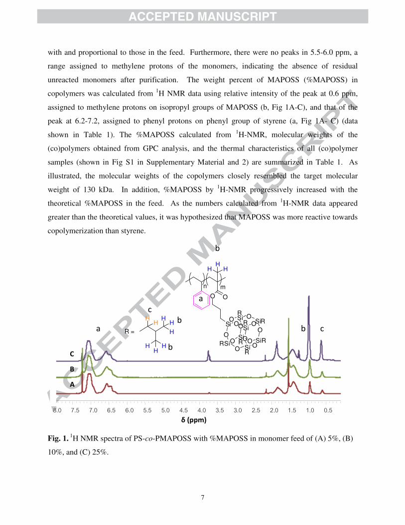
As revealed in Fig. 2, the derivative of TGA thermograms suggested that the decomposition
of the PS-co-PMAPOSS with %MAPOSS of 9% occurred at slightly lower temperature than that
of the PS. On the other hand, those with %MAPOSS of 14 and 36% decomposed at higher
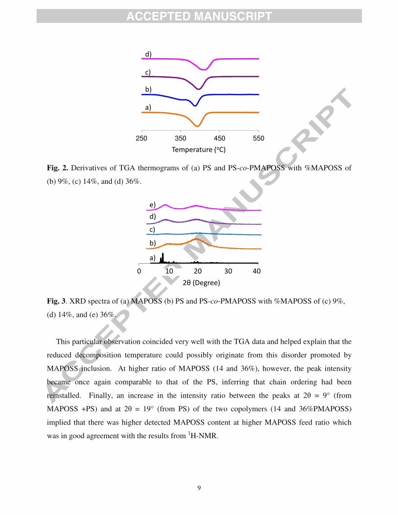
temperature than the PS. This phenomenon could be explained after a morphological
investigation of MAPOSS, PS, and the copolymers by XRD as shown in Fig.3. As for the
spectrum of PS, the lack of any sharp peaks and the presence of two broad peaks at 2θ = 10° and
19° (Fig. 3b) indicated that a majority of PS was amorphous, yet, with a certain degree of chain
packing. Nevertheless, at low %MAPOSS (9%), the spectral intensity (Fig. 3c) dropped
significantly implying that the addition of small amount of MAPOSS apparently disrupted the
packing of PS chains.
9
250 350 450 550
d)
c)
b)
a)
Temperature (oC)
Fig. 2. Derivatives of TGA thermograms of (a) PS and PS-co-PMAPOSS with %MAPOSS of
(b) 9%, (c) 14%, and (d) 36%.
0 10 20 30 400 10 20 30 40
a)
b)
c)
d)
e)
2θ (Degree)
Fig. 3. XRD spectra of (a) MAPOSS (b) PS and PS-co-PMAPOSS with %MAPOSS of (c) 9%,
(d) 14%, and (e) 36%.
This particular observation coincided very well with the TGA data and helped explain that the
reduced decomposition temperature could possibly originate from this disorder promoted by
MAPOSS inclusion. At higher ratio of MAPOSS (14 and 36%), however, the peak intensity
became once again comparable to that of the PS, inferring that chain ordering had been
reinstalled. Finally, an increase in the intensity ratio between the peaks at 2θ = 9° (from
MAPOSS +PS) and at 2θ = 19° (from PS) of the two copolymers (14 and 36%PMAPOSS)
implied that there was higher detected MAPOSS content at higher MAPOSS feed ratio which
was in good agreement with the results from 1H-NMR.
10
3.2 Electrospinning of (co)polymers
Previously, it has been shown in literatures that solvent has a strong impact on morphological
features of electrospun fiber [19-20]. In this research, single solvents (toluene, THF, DMF) and
mixtures of THF and DMF with various volume ratios were employed as media to solubilize the
copolymers for electrospinning. The concentration used was 20% in all cases. In terms of
solubility, PS could be dissolved in all three solvents, while the copolymers were soluble in
toluene and THF, but could only swell in DMF. As an addition of THF to DMF could increase
the solubility of the copolymers, the materials became completely soluble in THF/DMF mixture
as the ratio between THF and DMF reached 1:2. Although toluene was a good solvent for both
PS and copolymers, electrospinning of the polymer solution in toluene resulted in spraying of
large droplets without any fiber formation, presumably due to low dipole moment and
conductivity of toluene. Therefore, it was concluded that toluene was not a practical solvent for
electrospinning of these (co)polymers.
SEM micrographs of electrospun PS fibers are shown in Fig. S2 (Supplementary Material).
Through variation of solvents, it was found that, while PS was soluble in both THF and DMF,
using THF alone resulted almost exclusively in beads with very few fibers (Fig. S2a). Using
DMF and mixture of THF and DMF (Fig. S2b-d) as solvents gave fibers with very small number
of beads, which could be explained as a result of higher dipole moment and conductivity of DMF
than those of THF. Average fiber diameters and standard deviations of those fibers obtained
from DMF were higher than those from the solution in mixed solvents. There was, however,
very little difference in fiber diameters among those from solvent mixtures of different ratio (Fig.
S2b-c). The results were in good agreement with a previous report by Jarusuwannapoom and co-
workers, although the molecular weight of PS in the current case (158.9 kDa) was lower than
that of the aforementioned report [21].
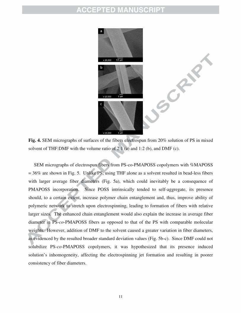
Closer inspection (Fig. 4) shows that these electrospun PS fibers had coarse surfaces, with
roughness appearing more pronounced with the increase of DMF content. The mechanism of
roughness evolution has been proposed in a publication by Lu and Xia, which involved
condensation of miniscule water droplets on the surface of fibers during evaporation of solvent,
leaving pores to develop on the surface during the course of subsequent dehydration [22].
11
Fig. 4. SEM micrographs of surfaces of the fibers electrospun from 20% solution of PS in mixed
solvent of THF:DMF with the volume ratio of 2:1 (a) and 1:2 (b), and DMF (c).
SEM micrographs of electrospun fibers from PS-co-PMAPOSS copolymers with %MAPOSS
= 36% are shown in Fig. 5. Unlike PS, using THF alone as a solvent resulted in bead-less fibers
with larger average fiber diameters (Fig. 5a), which could inevitably be a consequence of
PMAPOSS incorporation. Since POSS intrinsically tended to self-aggregate, its presence
should, to a certain extent, increase polymer chain entanglement and, thus, improve ability of
polymeric network to stretch upon electrospinning, leading to formation of fibers with relative
larger sizes. The enhanced chain entanglement would also explain the increase in average fiber
diameter in PS-co-PMAPOSS fibers as opposed to that of the PS with comparable molecular
weights. However, addition of DMF to the solvent caused a greater variation in fiber diameters,
as evidenced by the resulted broader standard deviation values (Fig. 5b-c). Since DMF could not
solubilize PS-co-PMAPOSS copolymers, it was hypothesized that its presence induced
solution’s inhomogeneity, affecting the electrospinning jet formation and resulting in poorer
consistency of fiber diameters.
12
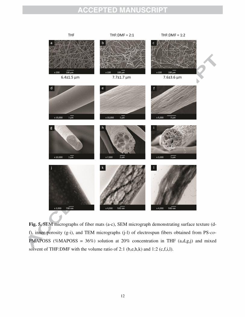
Fig. 5. SEM micrographs of fiber mats (a-c), SEM micrograph demonstrating surface texture (d-
f), inner porosity (g-i), and TEM micrographs (j-l) of electrospun fibers obtained from PS-co-
PMAPOSS (%MAPOSS = 36%) solution at 20% concentration in THF (a,d,g,j) and mixed
solvent of THF:DMF with the volume ratio of 2:1 (b,e,h,k) and 1:2 (c,f,i,l).
13
SEM analyses showed that electrospun fiber obtained from the THF solution of copolymers
(Fig. 5d) gave relatively smooth fibers, with little roughness. However, the surface of fibers
electrospun from the polymer solutions in mixed solvents showed fibrillar structures with
directional grooves along the fibers’ axis, resembling a “wood-like” feature. An increase of
DMF content in the solvent mixture further promoted the formation of fibril structures with even
more distinct grooves. Since the roughness of the fiber surface was different from that of PS, it
was hypothesized that structural development in the two cases progressed via different routes.
For this reason, peering into the internal structures of the fibers could shed light into the
mechanisms through which the observed roughness manifested. The interior of the fibers were
examined as in SEM cross-sectional images (Fig. 5g-i) and TEM micrographs of electrospun
fibers (Fig. 5j-l). The results revealed that the fibers fabricated from THF solution were mostly
dense with largely miniscule pores present, whereas those from mixed solvents exhibited
numerous pores of mixed and relatively larger sizes. The fibers from 2:1 THF:DMF mixture
possessed noticeable “sheath” and hollow pores, which resembled the cross-section of lotus root
(Fig. 5h). TEM micrographs (Fig. 5k) also confirmed that the outer part of the fibers consisted of
nanofibrillar structures while the inner part consisted of interconnected pores. In contrast, the
fibers from 1:2 THF:DMF mixture showed no discernible “sheath” but illustrated a large number
of small hollow pores similar to sponges (Fig. 5i). TEM micrograph shown in Fig. 5l further
revealed that the inner part of the fibers not only consisted of nanofibrillar structures similar to
those on the surface, but also accommodated numerous small pores throughout. As, incidentally,
the internal nanofibrillar structures observed in this study were similar to those reported
previously by Xue and co-workers as mentioned earlier, in our case the fibers contained many
more visible pores [22].
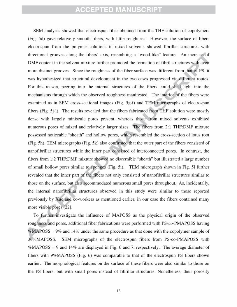
To further investigate the influence of MAPOSS as the physical origin of the observed
roughness and pores, additional fiber fabrications were performed with PS-co-PMAPOSS having
%MAPOSS = 9% and 14% under the same procedure as that done with the copolymer sample of
36%MAPOSS. SEM micrographs of the electrospun fibers from PS-co-PMAPOSS with
%MAPOSS = 9 and 14% are displayed in Fig. 6 and 7, respectively. The average diameter of
fibers with 9%MAPOSS (Fig. 6) was comparable to that of the electrospun PS fibers shown
earlier. The morphological features on the surface of these fibers were also similar to those on
the PS fibers, but with small pores instead of fibrillar structures. Nonetheless, their porosity
14
followed the same trend as the electrospun fibers obtained from the copolymer with higher POSS
described previously, being more prominent with the increase of DMF content in the mixed
solvent.
Fig. 6. SEM micrographs demonstrating overall morphology (a,b), surface texture (c,d), and
inner porosity (e,f) of electrospun fibers obtained from PS-co-PMAPOSS (%MAPOSS = 9%)
solution at 20% concentration in mixed solvent of THF:DMF with the volume ratio of 2:1 (a,c,e)
and 1:2 (b,d,f). Below the top row is the average diameter of the corresponding electrospun
fibers.
In the cases of fibers from PS-co-PMAPOSS copolymers with 14%MAPOSS (Fig. 7), the
resulting diameter was comparable to that of the sample with 36%MAPOSS. The morphological
features on surface and inner pore structures also followed the same predisposition as unveiled in
the fibers with higher POSS content, with fibrillar surface structure and porosity became more
distinct with the increase in DMF content. These results implied that in order to form
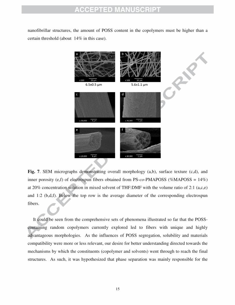
15
nanofibrillar structures, the amount of POSS content in the copolymers must be higher than a
certain threshold (about 14% in this case).
Fig. 7. SEM micrographs demonstrating overall morphology (a,b), surface texture (c,d), and
inner porosity (e,f) of electrospun fibers obtained from PS-co-PMAPOSS (%MAPOSS = 14%)
at 20% concentration solution in mixed solvent of THF:DMF with the volume ratio of 2:1 (a,c,e)
and 1:2 (b,d,f). Below the top row is the average diameter of the corresponding electrospun
fibers.
It could be seen from the comprehensive sets of phenomena illustrated so far that the POSS-
containing random copolymers currently explored led to fibers with unique and highly
advantageous morphologies. As the influences of POSS segregation, solubility and materials
compatibility were more or less relevant, our desire for better understanding directed towards the
mechanisms by which the constituents (copolymer and solvents) went through to reach the final
structures. As such, it was hypothesized that phase separation was mainly responsible for the
16
phenomena observed. Phase separation of polymers and formation of porous structure in
polymers were investigated by many research groups in the past.
Over a decade ago, Megelski et al. reported their pioneering work on pore generation in
electrospun nanofibers. Void in nanofibers manifested in various structures-from densely packed
and well-defined nanopores to relatively larger flat micropores. Considered generic in fibers
constituting a broad range of polymers, the case was hypothesized to correlate with high
volatility of solvents used in the processes [23]. In addition, Casper et al. investigated the effect
of molecular weight and humidity on fiber surface characteristics during their experiments with
electrospinning of polystyrene solutions [24]. The authors revealed that the increase in relative
humidity and molecular weight led to such profound effects as the increase in pore size, pore size
distribution and overall porosity. Dayal et al. theoretically peered into the internal structures of
nanofibers formed by solution-based electrospinning [25]. They have suggested that solvent
evaporation affecting the phase diagram of amorphous polymer solution was the morphological
determining factor for the internal pores.
Within the electrospinning scheme, Medeiros et al. investigated on the physical origin of the
relevance of humidity in their inquiries with a number of polymers such as PVA, PMMA, PVC,
PS and PLA in various solvents including toluene, DMF [26]. While pore manifestation was
varied with and influenced by types of polymers, component solubility and molecular weights,
the final structure was a genuine footprint of the competitive kinetics of phase separation and
solvent evaporation. As per end-use applications of solution-based phase separation, solvent
compatibility was taken for granted and explored to a great extent. Under DMF solvent system
and high humidity, Pai et al. attributed the presence of internal porosity in PS electrospun
nanofibers to the solvent’s miscibility with water [27]. This inherent characteristics investigated
diffusion of airborne water into the fiber, stimulating liquid (DMF)-liquid (water) phase
separation which preceded solidification of PS from DMF and the birth of voids in the vicinity
once apprehended by water. Suggested by the reported findings discussed above, phase
separation in polymer solutions leading to inner pores and structured surface and interfaces was
arguably one of the most complex phenomena. To grasp that under the dynamics of
electrospinning was even more challenging.
To further comprehend the unique structures of PS-co-PMAPOSS fibers and their
development, we carefully examined the samples’ surfaces utilizing SEM/EDS technique. As

17
seen in Table 2, the elemental composition of the PS-co-PMAPOSS fiber surface changed
accordingly with the solvent. With THF, a good solvent for both PS and PS-co-PMAPOSS, the
elemental composition of fiber almost matched the theoretical estimation calculated from that of
the bulk composition. In contrast, the addition of DMF caused a decrease in silicon signal, a
prominent footprint of MAPOSS moiety. Despite increase of oxygen content, oxidation of POSS
was unlikely to take place due to its oxidative stability [28]. While both PS and PMAPOSS
phases were well dispersed in THF, PS phase seemed to be more available at the surface than its
PMAPOSS counterpart when DMF was added.
Table 2
Elemental composition of the surface of fiber electrospun from PS-co-PMAPOSS (36 %
MAPOSS) obtained by SEM/EDS analysis compared to calculated data from 1H NMR.
THF:DMF (v/v)
Elemental Composition (%)
C O Si
calculated from 1H
NMR data
88.16 7.53 4.30
3:0 87.78 7.60 4.62
2:1 85.15 11.08 3.77
1:2 84.73 12.20 3.06
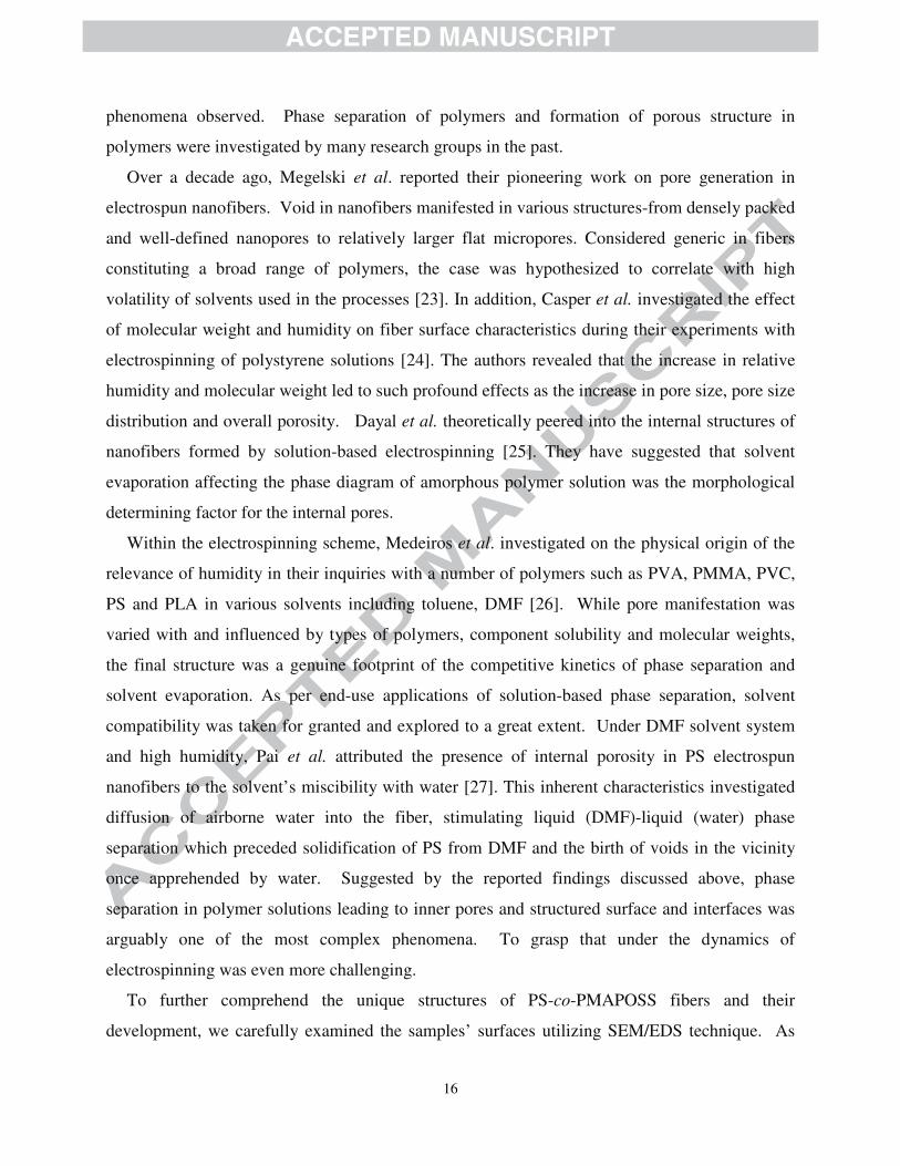
This result pointed out that the phase morphology of electrospun PS-co-PMAPOSS fibers was
influenced by the solvent composition. Furthermore, the unveiled influence of solvent
composition on the phase morphology of electrospun PS-co-PMAPOSS fibers might have hinted
at possible chain re-orientation upon solubility change. As a schematic representation, Fig. 8
depicted our proposed mechanism for fiber formation illustrating development of internal pores
and structured surfaces. In particular, when THF was used as a solvent (Fig. 8A), its rapid
evaporation rate caused the charged jet to shrink and kinetically trap both PS and PMAPOSS

18
together without phase separation. This mechanism gave rise to dense fiber with little pores left
from the evaporation of THF. In the cases of mixed solvents with THF: DMF of 2:1 (Fig. 8B),
the solvent would evaporate more slowly due to the high boiling point of DMF, causing
difference in solvent composition between what remained at the outer layer and that resided
within the core of the fibers. As a result, this led to the formation of fibrillar “sheath” on the
outer part. Subsequent evaporation of the remaining solvent (mainly DMF) drove the formation
of internal pores. As for the case of mixed solvent with THF: DMF of 1:2 (Fig. 8C), solvent
evaporation would be even more hindered, leaving larger DMF fraction trapped inside the fiber
core, originating the fibrillar structure throughout.
To further reveal the unique potential applications of the obtained organic-inorganic hybrid
fibers, chemical transformation was performed with thermal and plasma treatment. With its
organic-inorganic hybrid nature, POSS and POSS-containing fibrous composites were
hypothesized to possess an ability to convert to full silicon dioxide after high temperature
treatment. Even though the fibers electrospun solely from PS-co-PMAPOSS (36% MAPOSS)
could not tolerate the high heat (the fibrous structure was destroyed upon calcination at 400oC as
shown in Fig. S3 (Supplementary Material), addition of TEOS (5% of polymer weight) into the
spinning precursor solution led to fibers with better physical integrity after calcination as shown
in Fig. 9a.
Furthermore, an electrospun fiber mesh of PS-co-PMAPOSS was transferred into an oxygen
plasma chamber. After a given condition of plasma treatment, the resulting fibers were
examined under electron microscopy. Fig. 9b illustrated SEM micrograph of the plasma treated
nanofibers with their fibrous structures remained intact. Furthermore, after plasma treatment, the
water receding contact angle plummeted to almost 0°, implying emergence of hydrophilic silanol
groups in the samples. The results hinted at the potential of these hybrid materials after further
chemical modifications as backbones for a broad range of functional surfaces.
To enhance the functionality of the treated samples for even broader range of applications,
silanization by MeSiCl3 was carried out to chemically modify the surface characteristics of the
samples. First, fibers of PS-co-PMAPOSS/TEOS before plasma treatment showed high contact
angle (θ = 144°) and decrease to almost 0° after plasma treatment. Yet, after silanization, the
contact angle rose again (θ = 134°). Despite their preliminary nature, the results inexorably
19
suggested possibilities of surface modification on the developed hybrid structures for a broad
range of end use applications.
Fig. 8. Schematic illustration of proposed mechanism of formation of pores and roughness in PS-
co-PMAPOSS fibers electrospun from THF solution (A) and mixed solvent of THF and DMF
with THF:DMF volume ratio of 2:1 (B) and 1:2 (C). The left column shows charged jet of the
polymer solution. The middle column shows evaporation of solvent from the charged jet to form
fiber. The last column indicates the morphological features of the fiber.

20
Fig. 9. SEM micrographs of modified electrospun fibers obtained from PS-co-PMAPOSS (36%
MAPOSS): (a) after an addition of TEOS and calcination and (b) followed by plasma treatment.
Conclusions
Highly porous organic-inorganic hybrid fibers were fabricated via a combination of
electrospinning and solvent-driven phase separation. First, PS-co-PMAPOSS were successfully
synthesized with target molecular weight higher than 100 kDa to ensure electrospinnability via
concurrent ARGET ATRP-RAFT. The composition of MAPOSS in the copolymer calculated
from 1H NMR data progressively increased with the MAPOSS composition in the feed. PS-co-
PMAPOSS fiber mats were then fabricated using electrospinning with mixed THF and DMF as
solvents. Addition of DMF in solvent caused the as-spun fibers to display various degrees of
roughness and porosity. Investigation by SEM/EDS technique showed that elemental
composition of PS-co-PMAPOSS fiber surface changed according to solvent used. The decrease
in silicon content (MAPOSS moiety) on the surface was found together with the increase in
DMF content. This implied that the morphology of PS-co-PMAPOSS fiber was driven by DMF-
induced phase separation. Finally, preliminary tests suggested that highly porous PS-co-
PMAPOSS fiber could be modified with high temperature, plasma treatment, and silanization for
further novel applications.
Acknowledgements
Financial support for this work from the Thailand Graduate Institute of Science and
Technology (TGIST) sponsored by the National Science and Technology Development Agency
(NSTDA), Thailand, awarded to TP, VI, and VPH, the Higher Education Research Promotion
and National Research University Project of Thailand, Office of the Higher Education
Commission (Project Code AS505A), the Ratchadaphiseksomphot Endowment Fund of
Chulalongkorn University (RES560530126-AM), and the Thai Government Stimulus Package 2
21
(TKK2555), under the Project for Establishment of Comprehensive Center for Innovative Food,
Health Products and Agriculture are acknowledged.
References
[1] Fina A, Tabuani D, Frache A, Camino A. Polymer 2005:46;7855.
[2] Yen Y, Kuo S, Huang C, Chen J, Chang F. J Phys Chem B 2008:112;10821.
[3] Kim C, Kim B, Sheikh FA, Lee U, Khil M, Kim H. Macromolecules 2007:40;4823.
[4] Romo–Uribe A, Mather PT, Haddad TS, Lichtenhan JD. J Polym Sci Part B: Polym
Phys 1998:36;1857.
[5] Waddon AJ, Zheng L, Farris RJ, Coughlin EB. Nano Lett 2002:2;1149.
[6] Hirai T, Leolukman M, Jin S, Goseki R, Ishida Y, Ka-kimoto M, Hayakawa T, Ree M,
Gopalan P. Macromolecules 2009:42;8835.
[7] Zheng L, Hong S, Cardoen G, Burgaz E, Gido SP, Coughlin EB. Macromolecules
2004:37; 8606.
[8] Jamil H, Batool SS, Imran Z, Usman M, Rafiq MA, Willander M, Hassan MM. Ceram
Int 2012:38;2437.
[9] Pirzada T, Arvidson SA, Saquing CD, Shah SS, Khan SA. Langmuir 2012:28;5834.
[10] Baek J, Park J, Kang J, Kim D, Koh S, Kang Y. Bull Korean Chem Soc 2012:33;2694.
[11] Kim H, Lee H, Knowles JC. J. Biomed. Mater. Res. A 2006:79A;643.
[12] Mazinani S, Ajji A, Dubois C. Polymer 2009:50;3329.
[13] Cozza ES, Monticelli O, Marsano E. Macromol Mater Eng 2010:295;791.
[14] Xue Y, Wang H, Yu D, Feng L, Dai L, Wang X, Lin T, Chem Commun 2009:6418.
[15] Nicolaÿ R, Kwak Y, Matyjaszewski K. Angew Chem 2010:122;551.
[16] Kwak Y, Nicolaÿ R, Matyjaszewski K. Macromolecules 2008:41;6602.
[17] Magenau AJD, Kwak Y, Matyjaszewski K. Macromolecules 2010:43;9682.
[18] Pisuchpen T, Chaim-ngoen N, Intasanta N, Supaphol P, Hoven VP. Langmuir
2011:27;3654.
[19] Wannatong L, Sirivat A, Supaphol P. Polym Int 2004:53;1851.
[20] Uyar T, Besenbacher F. Polymer 2008:49;5336.
22
[21] Jarusuwannapoom T, Hongrojjanawiwat W, Jitjaicham S, Wannatong L, Nithitanakul
M, Pattamaprom C, Koombhongse P, Rangkupan R, Supaphol P. Eur Polym J
2005:41;409.
[22] Lu P, Xia Y. Langmuir 2013:29;7070.
[23] Megelski S, Stephens JS, Chase DB, Rabolt JF. Macromolecules 2002:35;8456.
[24] Casper CL, Stephens JS, Tassi NG, Chase DB, Rabolt JF. Macromolecules
2004:37;573.
[25] Dayal P, Liu J, Kumar S, Kyu T. Macromolecules 2007:40;7689.
[26] Medeiros ES, Mattoso LHC, Offeman RD, Wood DF, Orts WJ. Can J Chem
2008:86;590.
[27] Pai C, Boyce MC, Rutledge GC. Macromolecules 2009:42;2102.
[28] Baney RH, Itoh M, Sakakibara A, Suzuki T. Chem Rev 1995:95;1409.
23
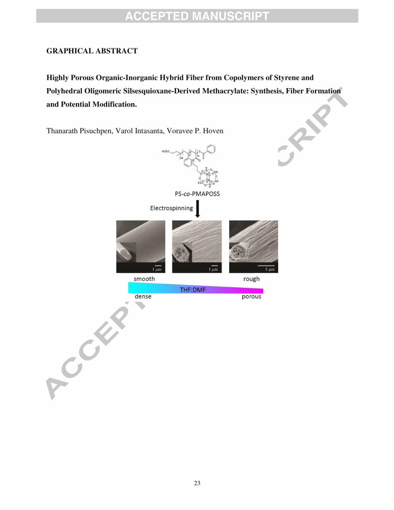
GRAPHICAL ABSTRACT
Highly Porous Organic-Inorganic Hybrid Fiber from Copolymers of Styrene and
Polyhedral Oligomeric Silsesquioxane-Derived Methacrylate: Synthesis, Fiber Formation
and Potential Modification.
Thanarath Pisuchpen, Varol Intasanta, Voravee P. Hoven
24
Highlights
• POSS-containing copolymers can be synthesized by concurrent ARGET ATRP-RAFT
• Thermal decomposition and solubility of PS was altered by PMAPOSS incorporation
• Characteristic of fibers electrospun from the copolymers was influenced by solvent
• Phase separation of the copolymer constitutes to the degree of fiber porosity
• The copolymer fibers can be modified with high temperature, plasma and silanization


