
HIGH PERFORMANCE HEAT RECOVERY UNITHRF SERIES
Nominal air fl ows from 790 to 4250 m3/h
SELECTION MANUAL
05
14
6
18
08
09
0
1
ENG


Index
Description of the unit 4Configurations 5Main components 6Unit diagram 7Accessories and options 8Technical data 10Dimensions 10Thermoregulation 11Ventilation control 13Characteristic curves size 008 15Characteristic curves size 010 18Characteristic curves size 013 21Characteristic curves size 020 24Characteristic curves size 031 27Characteristic curves size 042 30Performance internal hot water heating coil 33Performance internal hot water heating coil 36Performance external module water coils cold water operation 39

Selection manual
4
Description of the unit
The RPF series is a line of heat recovery units with per-
formance greater than 90% specially created for high
performance recovery of the energy from the expelled
air. It is suitable for installations in tertiary and indus-
trial environments such as offices, bars and restaurants,
meeting rooms, shops, school buildings, gyms, homes
for the elderly, and, in general, for all those structures
in which the reduction of energy costs is of significant
importance.
In order to be able to meet every need, there are 6
sizes with air flow rate from 200 m3/h to 4600 m3/h,
both in the horizontal configuration (except the size
042) and in the vertical one. The unit may be installed
on suspended ceiling, floor mounted or fitted exter-
nally.
The RPF recovery unit is a monoblock machine. It is
very compact and especially plug and play. It does not
require any particular interventions during installation
and fine-tuning is carried out directly in the factory.
The core of this product is the high efficiency alu-
minum plate heat recovery unit with countercurrent
exchange. The performance of the recovery unit is
greater than 90%, is EUROVENT certified, technically
innovative and operates with distribution of the air
flow through defined canalised paths at very low load
losses.
The other features and functionalities of the unit are:
• high efficiency air flow filtration (F7) for the flow of
outlet air;
• plug fan ventilation with permanent magnet syn-
chronous motor and EC electronic control with low
values of electric consumption. The impellers are
designed in such a way as to ensure a flow of air that
passes through the internal components with the
minimum level of noise;
• designed to reduce the overall value of the Specific
Fan Power;
• free-cooling and free-heating obtained thanks to
management of the locks in order to take full advan-
tage of the favourable conditions of the outside air;
• anti-freeze function in winter in case of extremely
cold temperatures;
• complete control of ventilation and of thermoregu-
lation with advanced energy saving features;
• integration of the power required through a wide
range of accessory devices;
• plug and play installation logic with BMS systems
interfacing;
• the environmental sound level is maintained at low
values for the precise soundproofing of the machine
and the careful selection of moving components.

Selection manual
5
Configurations
S
S
S
E
E
E
I
I
I
I
D
D D
D
Horizontal Confi guration right supply (top view)
Horizontal Confi guration left supply (top view)
Vertical Confi gurationright supply (view from accessible side)
Vertical Confi gurationleft supply (view from accessible side)
D = Discharge / Expulsion I = Intake S = Supply E = Extract

Selection manual
6
Main components
SUPPORT STRUCTURE
The structure of the unit is composed of an aluminum frame with thermal break profi le and multi-lip tubular seals to ensure the best sealing of the panels (sealing class L1 with leakage L1 and thermal bridge class TB2 according to EN 1886).The corner joints are made from nylon reinforced with fi bre glass.The panels have a thickness of 50 mm and are of the sandwich-type in pre-painted sheet RAL 9002 (exter-nal) and galvanised sheet metal (internal), insulated with polyurethane with density 45 kg/m3. The poly-urethane foam used has an eco-friendly water-based expander GWP=0 (Global Warming Potential) , which respects the environment and has an M1 fi re reaction classaccording to the standard NFP92-512:1986 (test no. LNE PV P115893 - DE/1). The sandwich panels are for the most part removable to facilitate and enable maintenance of the unit.The internal condensation collection tank is indepen-dent of the supporting structure of the unit and is easily extractable.Within the units there is a motorised by-pass lock (fully aluminum) controlled for management of the free cooling up to 100% depending on the external conditions.Standard fi tting is with mounting brackets for secur-ing to the ceiling or support feet (accessories) for fl oor-mounted installation.
HOT / COLD WATER COILS
These are made with micro-fi nned copper piping and aluminum fi ns, pre-painted aluminium, copper or tin-plated copper, secured through mechanical expan-sion of the pipes. They are supplied with 2 or 3-way valves.
FANS
The supply and extract fans are plug type with elec-tronic control (EC) permanent magnet synchronous motor. The impellers are designed in such a way as to ensure a
flow of air that passes through the internal components
with the minimum level of noise;
FILTERS
Access to the fi lters of the unit is secured via suitable
side (standard) or lower (optional) opening [reference
to horizontal version].
Standard insertion of an F7 fi lter on the intake air, ac-
cording to EN779, with low load losses; on the air ex-
tracted instead is inserted a G4 fi lter according to EN779
with low load losses.
RECOVERY UNIT
A EUROVENT certifi ed high-effi ciency cross-fl ow heat
recovery unit is used to recover heat.
Its performance is not less than 90% (EN308) on the basis of the external conditions: intake air -10°C/90% - extract air 20°C/50% - identical fl ow rates between supply and extract.Anautomatic defrost function is also inserted by opening the internal modulating lock and modula-tion with the intake fl ow or by electric defrosting coil (accessory).
The performanceof the KLINGENBURG recovery unitis EUROVENT certifi ed
ELECTRIC coils
The electric coils are managed by the thermoregulator.
They are made from a galvanised sheet metal frame
and are made by creating a series of modules, or
spiral piping, equipped with safety thermostats with
automatic reset, calibrated to intervene in the event of
absence of or poor ventilation.
They can be used both for pre-heating and as
internal heating instead of the water coil.
NOTE: only the internal electric heating coils are
modulating.
ELECTRICAL PANEL
The unit is equipped with an electric panel located on
board the machine, accessible laterally. The electrical
panel is isolated from the air flow in an appropriate
compartment. The power section comprises the main
switch with door interlock function, protection fuses
and fan contacts.
The control is programmable and is equipped with vis-
ible graphical built-in display which is accessible from
outside the machine.

Selection manual
7
D = Discharge I = Intake S = Supply E = Extract
Fansupply
Extract fan
Ser vocontrol locks
Flow switchsupply
Probetemperature a i r expulsion - defrost
Extract flow switch
Pre-heatingelectric coils
T e m p e r a t u r e probe external air intake
Temperature p r o b e a i r extract
Electricalpanel
Pressure switchexternal air fil-ters
S
E I
D
As per standard
Optional
Unit indicative diagram
P r e s s u r e switcha i r f i l t e r s extract
Hot electric / water coil
T e m p e r a t u r e probe supply
Pressure probePressure probe
Probe air qual-ity

Selection manual
8
ELECTRIC PRE-HEATING COILS (internal)
EH025F Coil 2.5 kW 230/1+N/50;EH037F Coil 3.75 kW 230/1+N/50;EH052F Coil 5.25 kW 400/3/50; EH067F Coil 6.75 kW 400/3/50; EH082F Coil 8.25 kW 400/3/50; EH180F Coil 18 kW 400/3/50;(only one choice is permitted)
HEATING COILS (internal)
HC3R Water heating coil;HC3R3V Water heating coil with 3-way valve supplied;HC3R2V Water heating coil with 2-way valve supplied;EH025H Electric coil2.5 kW 230/1+N/50;EH037H Electric coil3.75 kW 230/1+N/50 (*);EH038H Electric coil 3.75 kW 400/3/50;EH052H Electric coil 5,25 kW 400/3/50; EH067H Electric coil 6.75 kW 400/3/50;EH135H Electric coil 13.5 kW 400/3/50;EH025MH Electric coil2.5 kW 230/1+N/50
modulating;EH037MH Electric coil3.75 kW 230/1+N/50
modulating (*);EH038MH Electriccoil 3.75 kW 400/3/50
modulating;EH052MH Electric coil 5.25 kW 400/3/50
modulating; EH067MH Electric coil6.75 kW 400/3/50
modulating;EH135MH Electric coil 13.5 kW 400/3/50
modulating;(*) Not compatible if electric pre-heating coilis present(only one choice is permitted)
COOLING COILS (additional module)
CC3R Watercoil;CC3R3V Water coil with 3-way valve supplied;CC3R2V Water coil with 2-way valve supplied;
Operation with hot water is also provided (not compatible if there is an internal heating coil).(only one choice is permitted)
PROTECTIVE ROOF TPRF
INSPECTION OF FILTERS
SFI Side Inspection (standard);BFI Inspection from the lower side; (only one choice is permitted)
PRESSURE SWITCH FILTERS
DPS1 Pressure switch fi lters outside air; DPS2 Pressure switch fi lters outside air and
environment extract;(only one choice is permitted)
AIR FLOW SWITCH
SFS Flow switch supply fan;EFS Flow switch extract fan;
SUPPORT FEET
BSF Support feet for horizontal or vertical basic unit;
BSM Support feet for additional module
INTAKE ACCESSORIES
FLCI Tapered circular intake fl ange;FLPI Flat circular intake fl ange;GTAI Vibration damping joint intake; SRI Intake locks; CFAI Weatherproof hoods,
INTAKE LOCK ACCESSORIES
CMSRI Manual control;SCSRI Servocontrol ON/OFF;SCMSRI Servocontrol ON/OFF with spring return;(only one choice is permitted)
EXTRACT ACCESSORIES
FLCE Circular taperedextract fl ange;PLPE Flat circular extract fl ange; GTAE Vibration damping joint extract; SRE Extract locks;CFAE Weatherproof hoods,(only one choice is permitted)
EXTRACT LOCK ACCESSORIES
CMSRE Manual control;SCSRE Servocontrol ON/OFF;
Accessories and options

Selection manual
9
SCMSRE Servocontrol ON/OFF with spring return;(only one choice is permitted)
EXPULSION ACCESSORIES
FLCD Circular taperedexpulsionfl ange;GTAD Vibration damping joint expulsion SRD Expulsion locksCFAD Weatherproof hoods
EXPULSION LOCK ACCESSORIES
CMSRD Manual control;CMSRD Servocontrol ON/OFF;SCMSRD Servocontrol ON/OFF with spring return;(only one choice is permitted)
SUPPLY ACCESSORIES
FLCS Circular taperedsupplyfl ange;GTAS Vibration damping joint supplySRS Supply locksCFAS Weatherproof hoods,
SUPPLY LOCK ACCESSORIES
CMSRS Manual control;SCSRS Servocontrol ON/OFF;SCMSRS Servocontrol ON/OFF with spring return;(only one choice is permitted)
SILENCERS ENVIRONMENT SIDE ( additional mod-
ule)
SZS SuplysilencersSZEExtract silencers
SILENCERS EXTERNAL SIDE ( additional module)
SZI Intake silencersSZD Expulsion silencers
FANS CONTROL
CMF Electrical panel + manual fan speed control CPOC Electrical panel + fan control in constant
fl owCPRC Electrical panel + fan control under constant
pressureCCO2 Electrical panel + fan control with CO 2
probeCVOC Electrical panel + fan control in fl ow with
VOC probe CPOCO2 Electrical panel + fan control in constant
fl ow with CO 2 probe CPOVOC Electrical panel + fan control in constant
fl ow with VOCprobe (only one choice is permitted)
THERMOREGULATION
CTR Extract temperature controlCTS Supply temperature control [only if
modulating actuators (valves-resistance) ](only one choice is permitted)
COMMUNICATION PROTOCOL
PC485 ModBus RTU - RS485PCPFB Profi bus DP Slave - V0PCTCP Ethernet ModBus TCP(only one choice is permitted)
REMOTE PANEL RCP

Selection manual
10
C
A B
82 D 80 D 82
57
E5
7
200200
Rated technical data
Model 008 010 013 020 031 042
Rated air fl ow rate supply and extract m3/h 790 1000 1300 2000 3100 4250
Minimum air fl ow rate supply and extract m3/h 200 200 400 1000 1000 1300
Maximum air fl ow rate supply and extract m3/h 980 1260 1530 2350 3700 4600
Nominal rated static pressure supply and extract Pa 200 250 250 250 250 225
Recovered total thermal power(1) kW 7.2 9.1 11.8 18.1 28.1 38.5
Performance in intake (EN308)(1) % 90 90 90 90 90 90
Total number fans 2 2 2 2 2 2
Total rated input power fans(2) kW 0.31 0.47 0.66 1.16 1.55 2.50
Total maximum input power(2) kW 0.60 1.24 1.26 1.66 5.26 5.26
Total maximum input current(2) A 4,6 7.5 7.5 9.3 11.1 11.1
Power supply unit(2) V-Ph230-1+N
50Hz
230-1+N
50Hz
230-1+N
50Hz
230-1+N
50Hz
400-3-
50Hz
400-3-
50Hz
Confi guration Horizontal Vertical
Model A (mm) B (mm) C (mm) D (mm) E (mm) A (mm) B (mm) C (mm) D (mm) E (mm)
008 1915 1054 450 405 336 1915 1054 450 430 286
010 1915 1258 450 507 336 1915 1258 450 532 286
013 2174 1374 524 565 410 2174 1374 524 590 360
020 2334 1694 560 725 446 2334 1694 560 750 396
031 2654 1948 700 852 586 2654 1948 700 877 536
042 - - - - - 2974 1550 1130 678 966
Supply Extract
1) Air conditions: intake -10 °C, 90 %UR and extract 20°C, 50% UR; 2) Basic version
Overall dimensions

Selection manual
11
Thermoregulation
MAIN OPERATION LOGICS
The unit is set to work, both in cooling and heating,
according to 2 main operation logics:
1. COMFORT: this is the standard mode of operation
2. ECONOMY: this is the mode of operation at reduced
speed.
During operation in Economy mode the following oper-
ation logics are adopted:
• ventilation is reduced
• if the unit is working in heating, a lower set point
temperature is adopted
• if the unit is working in cooling, a higher set point
temperature is adopted
HEATING OPERATION
Heating takes place according to the following two modes.
Heating with hot water coils
The supply air flow is heated by means of hot water coil. Adjustment is possible via a 2- or 3-way valve that regulates the flow of water from 0% to 100%.
Heating via electric coils
The supply air flow is heated by means of electric coils. The electric coils may be modulating or step (2 step or 3 with possible adjustments). NOTE: the main heating coils can be modulating or step while the pre-heating coils can only be step.
COOLING OPERATION
Cooling takes place according to the following mode.
Cooling with cold water coils
The supply air flow is cooled by means of cold water coils. Adjustment is possible via a 2- or 3-way valve that regulates the flow of water.
FREE COOLING / FREE HEATING OPERATION
Depending on the settings of the parameters and the
external environmental conditions the unit can operate
in a condition of free cooling or free heating.
Cooling by free cooling
When the difference between the internal and exter-nal temperature reaches a certain preset value, the unit goes into free cooling mode. During this period the by-pass lock is opened and the flow of outside air
is sent to the area to be air-conditioned without pass-ing through the recovery unit. Cooling in free cooling remains active for an adjustable maximum amount of time.
Heating by free heating
When the difference between the internal and external
temperature reaches a certain preset value, the unit
goes into free heating mode. During this period the
by-pass lock is opened and the flow of outside air is
sent to the area to be air-conditioned without passing
through the recovery unit. Heating in free cooling heat-
ing remains active for an adjustable maximum amount
of time.
OPERATION IN NIGHT COOLING MODE
Night cooling mode allows night-time refreshment forced in a way similar to free cooling mode.
SEASON CHANGE MODE
The functionality mode change from winter to sum-mer (and vice versa) can be performed manually or automatically (via external temperature probe or adjustment). See the user adjustment manual under the heading "Operation mode setting".
ANTIFREEZE FUNCTION (if provided)
The antifreeze function is provided to prevent the for-
mation of ice on the recovery unit and on the water coil
when the temperature detected by the expulsion probe
falls below a certain value.
The antifreeze function is carried out in the following
two ways.
Anti-freeze function via ventilation and locks
In this case, prevention of the formation of ice within the unit is carried out by the reduction of the speed of rotation of the supply fan (the extract fan is not involved) and opening of the by-pass lock of the recovery unit at a later time.
Anti-freeze function via electric coils
In this case the prevention of the formation of ice within the unit is carried out via heating of the exter-nal air flow.
NOTE: The antifreeze function is implemented at the time of selection of the machine or through interven-

Selection manual
12
tion of the assistance service in the version with use of fans and locks or in the version with use of electric coils. Both versions cannot be implemented on the same unit.
FIRE - SMOKE ALARM MANAGEMENT
Where the fire-smoke alarm is activated, there are 3 adjustment logics which can be set at the time of selection of the machine or subsequently with inter-vention of the assistance service.
1. All Off 2. Fan On 3. Extraction
Fan extract OFF MAX MAX
Fan supply OFF MAX OFF
External locks
OFF ON ON
Thermo-regulation
OFF OFF OFF
NOTE: The heat recovery unit is not a fume extractor
OPENING / CLOSING OF THE LOCKS
The internal and external locks are controlled by the
ventilation. With fans running the locks are open while
with the fans off the locks are closed.

Selection manual
13
Ventilation control
OPERATINGMODE
The unit is configured at the factory according to the modes 2 - 3 - 4 - 5 described below. In the event of a fault or with alarm notification the machine passes automatically to mode 1 (CMF).Once the machine configuration has been chosen it is not possible to go from one type of adjustment to another.
1. Manual ventilation control mode - CMF
This mode enables manual and independent control of
the rotational speed of the fans. The speed of rotation of
the supply and extract fan is set by means of the control
keyboard.
E C
2. Ventilation control mode in constant flow rate -
CPOC
This operation mode involves maintaining of the con-stant flow of supply and extraction (within the limits of operation of the fans). The supply and extraction flow rates can be set independently. With a variation of internal load (for example, due to increased dirt in the filters) or external load losses, the unit maintains the pre-established flow rates set.
P
Q
E
C
Measurements of the flow rates of supply and extrac-tion are carried out by pressure probes positioned inside the machine. In the event of a fault of the pres-sure probes or with alarm notification the ventilation control mode passes into manual (CMF). The unit is configured at the factory with the flow rate of supply and extraction requested at the time of selection.
Adjustment is m3/h.
3. Ventilation control mode in constant pressure -
CPRC
This operation mode involves maintaining of the con-stant pressure of supply and extraction (within the limits of operation of the fans). The supply and extrac-tion pressures can be set independently.
P
Q
PC
Measurement of the pressures of supply and extrac-tion are carried out by pressure probes provided and located on the channels (for installation of the pres-sure probe, see the respective paragraph in the instal-lation manual).In the event of a fault of the pressure probes or with alarm notification the ventilation control mode passes into manual (CMF). The unit is configured at the facto-ry with the pressure of supply and extraction request-ed at the time of selection.The adjustment is in Pascal units (Pa).
4. Ventilation control mode with CO2 probe or VOC
- CCO2 / CVOC probe
This mode of operation involves maintaining the pre-determined sets of air quality through variation of the speed of the fans. The quality of the air is detected via the CO2 probe or VOC probe, located at the extraction point.In the event of a fault of the CO2 probe or of the VOC probe or with alarm notification, the ventilation con-trol mode passes into manual (CMF).

Selection manual
14
P
CE
Q
5. Ventilation control mode with CO2 probe or VOC
- probe in constant flow CPOCO2 / CPOVOC
This mode of operation involves maintaining of the constant flow (within a certain range) for the value of air quality set.
P
Q
E
C
In case of failure of the CO2 probe or the VOC probe, the control mode passes into the control mode of the constant pressure flow rate.In the case of a failure of the pressure probe the con-trol mode passes into the control mode via the CO2 probe or VOC probe.In the event of a fault of the CO2 probe or of the VOC probe and the pressure probe the control mode pass-es into manual (CMF).
C = operation in comfort mode
C = operation in economy mode
PC = operation under constant pressure
p: pressure
Q: flow rate

78,0
80,0
82,0
84,0
86,0
88,0
90,0
92,0
94,0
96,0
100 200 300 400 500 600 700 800 900 1000 1100
0,0
0,5
1,0
1,5
2,0
2,5
3,0
3,5
4,0
4,5
5,0
100 200 300 400 500 600 700 800 900 1000 1100
SPECIFIC FAN POWER SIZE 008
SF
P [
kW/m
c/s]
Flow rate [m3/h]
Basic
mac
hine
rate
d sta
tic p
ress
ure e
xpre
ssed
in Pa
SFP maximum speed
400
350
300 250
200 150 100 50
The values refer to both the fans at the same fl ow rate
30
35
40
45
50
55
60
100 200 300 400 500 600 700 800 900 1000 1100
SOUND POWER EXTERNAL CASING SIZE 008
Lw[d
B(A
)]
Flow rate [m3/h]
400 350 300 250
200
150
100
50 Basic
mac
hine
rate
d sta
tic p
ress
ure e
xpre
ssed
in Pa
The values refer to both the fans at the same fl ow rate
Selection manual
15
PERFORMANCE RECOVERY UNIT SIZE 008
Pe
rfo
rma
nce
[%
]
Flow rate [m3/h]
Air
exp
elle
d a
t 2
0°C
an
d 5
0%
u.r.
-10°C 90%
-5°C 90%
0°C 90%
5°C 90%
Characteristic curves size 008

Selection manual
16
0
100
200
300
400
500
600
700
100 200 300 400 500 600 700 800 900 1000 1100
FLOW RATE PREVALENCE SUPPLY SIZE 008
Sta
tic
pre
ssu
re [
Pa
]
Flow rate [m3/h]
Maximum and rated prevalence
Minimum prevalence
0
0,02
0,04
0,06
0,08
0,1
0,12
0,14
0,16
0,18
100 200 300 400 500 600 700 800 900 1000 1100
ELECTRIC POWER INPUT SUPPLY FAN SIZE 008
Po
we
r [k
W]
Flow rate [m3/h]
Maximum speed
400 350 300 250 200 150 100 50 Ba
sic m
achi
ne ra
ted
static
pre
ssur
e exp
ress
ed in
Pa
40
45
50
55
60
65
70
75
80
100 200 300 400 500 600 700 800 900 1000 1100
OVERALL SOUND POWER SUPPLY SIZE 008
Lw[d
B(A
)]
Flow rate [m3/h]
400 350 300 250 200 150
100
50
Basic
mac
hine
rate
d sta
tic p
ress
ure e
xpre
ssed
in Pa

Selection manual
17
0
100
200
300
400
500
600
700
100 200 300 400 500 600 700 800 900 1000 1100
Sta
tic
pre
ssu
re [
Pa
]
FLOW RATE PREVALENCE EXTRACT SIZE 008
Flow rate [m3/h]
Maximum and rated prevalence
Minimum prevalence
0
0,02
0,04
0,06
0,08
0,1
0,12
0,14
0,16
0,18
100 200 300 400 500 600 700 800 900 1000 1100
Po
we
r [k
W]
Flow rate [m3/h]
Maximum speed
400 350 300 250 200 150 100 50 Ba
sic m
achi
ne ra
ted
static
pre
ssur
e exp
ress
ed in
Pa
ELECTRIC POWER INPUT FAN EXTRACT SIZE 008
78,0
80,0
82,0
84,0
86,0
88,0
90,0
92,0
94,0
96,0
100 200 300 400 500 600 700 800 900 1000 1100
OVERALL SOUND POWER EXTRACT SIZE 008
Lw[d
B(A
)]
Flow rate [m3/h]
400 350
300 250
200
150
100
50
Basic
mac
hine
rate
d sta
tic p
ress
ure e
xpre
ssed
in Pa

78
80
82
84
86
88
90
92
94
96
98
100 300 500 700 900 1100 1300
PERFORMANCE RECOVERY UNIT SIZE 010
Pe
rfo
rma
nce
[%
]
Flow rate [m3/h]
Air
exp
elle
d a
t 2
0°C
an
d 5
0%
u.r.
-10°C 90%
-5°C 90%
0°C 90%
5°C 90%
0
1
2
3
4
5
6
7
8
9
10
11
100 300 500 700 900 1100 1300
SPECIFIC FAN POWER SIZE 010
SF
P [
kW/m
c/s]
Flow rate [m3/h]
Maximum speed
400
350 300 250 200 150 100
Rated speed
The values refer to both the fans at the same fl ow rate
Basic
mac
hine
rate
d sta
tic p
ress
ure e
xpre
ssed
in Pa
30
35
40
45
50
55
60
100 200 300 400 500 600 700 800 900 1000 1100 1200 1300
SOUND POWER EXTERNAL CASING SIZE 010
Lw[d
B(A
)]
Flow rate [m3/h]
400 350 300 250
200
150
100
Basic
mac
hine
rate
d sta
tic p
ress
ure e
xpre
ssed
in Pa
The values refer to both the fans at the same fl ow rate
Selection manual
18 00000000
Characteristic curves size 010

0
200
400
600
800
1000
1200
100 300 500 700 900 1100 1300
FLOW PREVALENCE SUPPLY 010
Sta
tic
pre
ssu
re [
Pa
]
Flow rate [m3/h]
Maximum prevalence
Minimum prevalence
Rated prevalence
0
0,05
0,1
0,15
0,2
0,25
0,3
0,35
0,4
0,45
0,5
100 300 500 700 900 1100 1300
ELECTRIC POWER INPUT SUPPLY FAN SIZE 010
Po
we
r [k
W]
Maximum speed
400 350 300 250
200 150
100 Rated speed
Basic
mac
hine
rate
d sta
tic p
ress
ure e
xpre
ssed
in Pa
Flow rate [m3/h]
55
60
65
70
75
80
100 200 300 400 500 600 700 800 900 1000 1100 1200 1300
OVERALL SOUND POWER EXTRACT SIZE 010
Lw[d
B(A
)]
Flow rate [m3/h]
400 350 300 250
200
150
100
Basic
mac
hine
rate
d sta
tic p
ress
ure e
xpre
ssed
in Pa
Selection manual
19

0
200
400
600
800
1000
1200
100 300 500 700 900 1100 1300
Sta
tic
pre
ssu
re [
Pa
]
FLOW RATE PREVALENCE EXTRACT SIZE 010
Flow rate [m3/h]
Maximum prevalence
Minimum prevalence
Rated prevalence
0
0,05
0,1
0,15
0,2
0,25
0,3
0,35
0,4
0,45
0,5
100 300 500 700 900 1100 1300
ELECTRIC POWER INPUT FAN EXTRACT SIZE 010
Po
we
r [k
W]
Flow rate [m3/h]
Maximum speed
400 350 300 250
Rated speed 200 150
100
Basic
mac
hine
rate
d sta
tic p
ress
ure e
xpre
ssed
in Pa
45
50
55
60
65
70
100 200 300 400 500 600 700 800 900 1000 1100 1200 1300
OVERALL SOUND POWER EXTRACT SIZE 010
Lw[d
B(A
)]
Flow rate [m3/h]
400 350
300
250
200
150
100
Basic
mac
hine
rate
d sta
tic p
ress
ure e
xpre
ssed
in Pa
Selection manual
20

Selection manual
21
Characteristic curves size 013
78
80
82
84
86
88
90
92
94
96
300 500 700 900 1100 1300 1500
PERFORMANCE RECOVERY UNIT SIZE 013
Pe
rfo
rma
nce
[%
]
Flow rate [m3/h]
Air
exp
elle
d a
t 2
0°C
an
d 5
0%
u.r.
-10°C 90%
-5°C 90%
0°C 90%
5°C 90%
0,5
1,0
1,5
2,0
2,5
3,0
3,5
4,0
4,5
5,0
5,5
6,0
6,5
300 500 700 900 1100 1300 1500
SPECIFIC FAN POWER SIZE 013
SF
P [
kW/m
c/s]
Flow rate [m3/h]
Speed maximum
400 350 300 250 200 150 100
Speed rated The values refer to both the fans at the same fl ow rate
Basic
mac
hine
rate
d sta
tic p
ress
ure e
xpre
ssed
in Pa
35
40
45
50
55
60
300 500 700 900 1100 1300 1500
SOUND POWER EXTERNAL CASING SIZE 013
Lw[d
B(A
)]
Flow rate [m3/h]
400
350
300
250
200
150
100 Basic
mac
hine
rate
d sta
tic p
ress
ure e
xpre
ssed
in Pa
The values refer to both the fans at the same fl ow rate

Selection manual
22
0
200
400
600
800
1000
300 500 700 900 1100 1300 1500
FLOW RATE PREVALENCE SUPPLY SIZE 013
Sta
tic
pre
ssu
re [
Pa
]
Flow rate [m3/h]
Maximum prevalence
Minimum prevalence
Rated prevalence
0
0,05
0,1
0,15
0,2
0,25
0,3
0,35
0,4
0,45
0,5
300 500 700 900 1100 1300 1500
ELECTRIC POWER INPUT SUPPLY FAN SIZE 013
Po
we
r [k
W]
Flow rate [m3/h]
Maximum speed
400 350 300 250 200 150 100
Rated speed
Basic
mac
hine
rate
d sta
tic p
ress
ure e
xpre
ssed
in Pa
55
60
65
70
75
80
300 500 700 900 1100 1300 1500
OVERALL SOUND POWER EXTRACT SIZE 013
Lw[d
B(A
)]
Flow rate [m3/h]
400
350
300
250
200
150
100 Basic
mac
hine
rate
d sta
tic p
ress
ure e
xpre
ssed
in Pa

Selection manual
23
0
200
400
600
800
1000
300 500 700 900 1100 1300 1500
Sta
tic
pre
ssu
re [
Pa
]
FLOW RATE PREVALENCE EXTRACT SIZE 013
Flow rate [m3/h]
Maximum prevalence
Minimum prevalence
Rated prevalence
0
0,05
0,1
0,15
0,2
0,25
0,3
0,35
0,4
0,45
0,5
300 500 700 900 1100 1300 1500
ELECTRIC POWER INPUT FAN RECOVERY SIZE 013
Po
we
r [k
W]
Flow rate [m3/h]
Maximum speed
400 350 300 250 200 150 100
Basic
mac
hine
rate
d sta
tic p
ress
ure e
xpre
ssed
in Pa
45
50
55
60
65
70
300 500 700 900 1100 1300 1500
Lw[d
B(A
)]
Flow rate [m3/h]
400
350
300
250
200
150
100
Basic
mac
hine
rate
d sta
tic p
ress
ure e
xpre
ssed
in Pa
OVERALL SOUND POWER EXTRACT SIZE 013

Selection manual
24
78
80
82
84
86
88
90
92
94
800 1000 1200 1400 1600 1800 2000 2200 2400
PERFORMANCE RECOVERY UNIT SIZE 020
Pe
rfo
rma
nce
[%
]
Flow rate [m3/h]
Air
exp
elle
d a
t 2
0°C
an
d 5
0%
u.r.
-10°C 90%
-5°C 90%
0°C 90%
5°C 90%
Characteristic curves size 020
0,5
1,0
1,5
2,0
2,5
3,0
3,5
4,0
800 1000 1200 1400 1600 1800 2000 2200 2400
SPECIFIC FAN POWER SIZE 020
SF
P [
kW/m
c/s]
Flow rate [m3/h]
Maximum speed
400
350
300
250
200
150
100
Rated speed
The values refer to both the fans at the same fl ow rate
Basic
mac
hine
rate
d sta
tic p
ress
ure e
xpre
ssed
in Pa
40
42
44
46
48
50
52
54
56
58
800 1000 1200 1400 1600 1800 2000 2200 2400
SOUND POWER EXTERNAL CASING SIZE 020
Lw[d
B(A
)]
Flow rate [m3/h]
400
350
300
250
200
150
100
Basic
mac
hine
rate
d sta
tic p
ress
ure e
xpre
ssed
in Pa
The values refer to both the fans at the same fl ow rate

Selection manual
25
0
100
200
300
400
500
600
700
800
800 1000 1200 1400 1600 1800 2000 2200 2400
FLOW RATE PREVALENCE SUPPLY SIZE 020
Sta
tic
pre
ssu
re [
Pa
]
Flow rate [m3/h]
Maximum prevalence
Minimum prevalence
Rated prevalence
0
0,1
0,2
0,3
0,4
0,5
0,6
0,7
0,8
800 1000 1200 1400 1600 1800 2000 2200 2400
ELECTRIC POWER INPUT SUPPLY FAN SIZE 020
Po
we
r [k
W]
Flow rate [m3/h]
Maximum speed
400 350 300 250 200 150 100
Rated speed
Basic
mac
hine
rate
d sta
tic p
ress
ure e
xpre
ssed
in Pa
62
64
66
68
70
72
74
76
78
800 1000 1200 1400 1600 1800 2000 2200 2400
OVERALL SOUND POWER SUPPLY SIZE 020
Lw[d
B(A
)]
400
350
300
250
200
150
100 Basic
mac
hine
rate
d sta
tic p
ress
ure e
xpre
ssed
in Pa
Flow rate [m3/h]

Selection manual
26
0
100
200
300
400
500
600
700
800
800 1000 1200 1400 1600 1800 2000 2200 2400
Sta
tic
pre
ssu
re [
Pa
]
FLOW RATE PREVALENCE EXTRACT SIZE 020
Flow rate [m3/h]
Maximum prevalence
Minimum prevalence
Rated prevalence
0
0,1
0,2
0,3
0,4
0,5
0,6
0,7
0,8
800 1000 1200 1400 1600 1800 2000 2200 2400
ELECTRIC POWER INPUT FAN RECOVERY SIZE 020
Po
we
r [k
W]
Flow rate [m3/h]
Maximum speed
400 350 300 250 200 150 100
Rated speed
Basic
mac
hine
rate
d sta
tic p
ress
ure e
xpre
ssed
in Pa
52
54
56
58
60
62
64
66
800 1000 1200 1400 1600 1800 2000 2200 2400
OVERALL SOUND POWER EXTRACT SIZE 020
Lw[d
B(A
)]
Flow rate [m3/h]
400
350
300
250
200
150
100
Basic
mac
hine
rate
d sta
tic p
ress
ure e
xpre
ssed
in Pa

78
80
82
84
86
88
90
92
94
800 1300 1800 2300 2800 3300 3800
Selection manual
27
PERFORMANCE RECOVERY UNIT SIZE 031
Pe
rfo
rma
nce
[%
]
Flow rate [m3/h]
Air
exp
elle
d a
t 2
0°C
an
d 5
0%
u.r.
-10°C 90%
-5°C 90%
0°C 90%
5°C 90%
Characteristic curves size 031
0,5
1,0
1,5
2,0
2,5
3,0
3,5
4,0
4,5
5,0
800 1300 1800 2300 2800 3300 3800
SPECIFIC FAN POWER SIZE 031
SF
P [
kW/m
c/s]
Flow rate [m3/h]
Maximum speed
400
350
300
250
200
150
100
Rated speedThe values refer to both the fans at the same fl ow rate
Basic
mac
hine
rate
d sta
tic p
ress
ure e
xpre
ssed
in Pa
40
42
44
46
48
50
52
54
56
58
800 1300 1800 2300 2800 3300 3800
SOUND POWER EXTERNAL CASING SIZE 031
Lw[d
B(A
)]
Flow rate [m3/h]
400
Basic
mac
hine
rate
d st
atic
pre
ssur
e ex
pres
sed
in P
a
350
300
250
200
150
100
The values refer to both the fans at the same fl ow rate

Selection manual
28
0
100
200
300
400
500
600
700
800
900
800 1300 1800 2300 2800 3300 3800
FLOW RATE PREVALENCE SUPPLY SIZE 031
Sta
tic
pre
ssu
re [
Pa
]
Flow rate [m3/h]
Maximum prevalence
Minimum prevalence
Rated prevalence
0
0,1
0,2
0,3
0,4
0,5
0,6
0,7
0,8
0,9
1
800 1300 1800 2300 2800 3300 3800
ELECTRIC POWER INPUT SUPPLY FAN SIZE 031
Po
we
r [k
W]
Flow rate [m3/h]
Maximum speed
400 350 300 250 200 150 100
Rated speed
Basic
mac
hine
rate
d sta
tic p
ress
ure e
xpre
ssed
in Pa
55
60
65
70
75
80
800 1300 1800 2300 2800 3300 3800
OVERALL SOUND POWER SUPPLY SIZE 031
Lw[d
B(A
)]
Flow rate [m3/h]
400 350
300
250
200
150
100
Basic
mac
hine
rate
d sta
tic p
ress
ure e
xpre
ssed
in Pa

Selection manual
29
0
100
200
300
400
500
600
700
800
900
800 1300 1800 2300 2800 3300 3800
Sta
tic
pre
ssu
re [
Pa
]
FLOW RATE PREVALENCE EXTRACT SIZE 031
Flow rate [m3/h]
Maximum prevalence
Minimum prevalence
Rated prevalence
0,0
0,1
0,2
0,3
0,4
0,5
0,6
0,7
0,8
0,9
1,0
800 1300 1800 2300 2800 3300 3800
ELECTRIC POWER INPUT FAN EXTRACT SIZE 031
Po
we
r [k
W]
Flow rate [m3/h]
Maximum speed
400 350 300 250 200 150 100
Rated speed
Basic
mac
hine
rate
d sta
tic p
ress
ure e
xpre
ssed
in Pa
45
50
55
60
65
70
800 1300 1800 2300 2800 3300 3800
OVERALL SOUND POWER EXTRACT SIZE 031
Lw[d
B(A
)]
Flow rate [m3/h]
400
350
300
250
200
150
100
Basic
mac
hine
rate
d sta
tic p
ress
ure e
xpre
ssed
in Pa

0,0
1,0
2,0
3,0
4,0
5,0
6,0
800 1300 1800 2300 2800 3300 3800 4300 4800
78
80
82
84
86
88
90
92
94
96
800 1300 1800 2300 2800 3300 3800 4300 4800
Selection manual
30
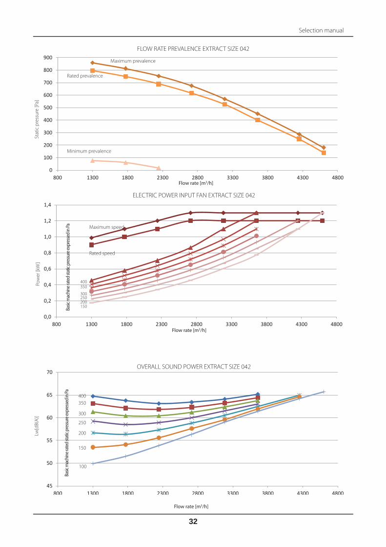
SPECIFIC FAN POWER SIZE 042
SF
P [
kW/m
c/s]
Flow rate [m3/h]
Maximum speed
400 350
300
250 200 150 100
Rated speed The values refer to both the fans at the same fl ow rate
Basic
mac
hine
rate
d sta
tic p
ress
ure e
xpre
ssed
in Pa
Air
exp
elle
d a
t 2
0°C
an
d 5
0%
u.r.
Pe
rfo
rma
nce
[%
]
-10°C 90%
-5°C 90%
0°C 90%
5°C 90%
Flow rate [m3/h]
PERFORMANCE RECOVERY UNIT SIZE 042
Characteristic curves size 042
40
45
50
55
60
65
800 1300 1800 2300 2800 3300 3800 4300 4800
SOUND POWER EXTERNAL CASING SIZE 042
Lw[d
B(A
)]
Flow rate [m3/h]
400
350
300
250
200
150
100
Basic
mac
hine
rate
d sta
tic p
ress
ure e
xpre
ssed
in Pa
The values refer to both the fans at the same fl ow rate

Selection manual
31
0
100
200
300
400
500
600
700
800
900
800 1300 1800 2300 2800 3300 3800 4300 4800
FLOW RATE PREVALENCE SUPPLY SIZE 042
Sta
tic
pre
ssu
re [
Pa
]
Flow rate [m3/h]
Maximum prevalence
Minimum prevalence
Rated prevalence
0,0
0,2
0,4
0,6
0,8
1,0
1,2
1,4
800 1300 1800 2300 2800 3300 3800 4300 4800
ELECTRIC POWER INPUT SUPPLY FAN SIZE 042
Po
we
r [k
W]
Flow rate [m3/h]
Maximum speed
400 350 300 250 200 150 100
Rated speed
Basic
mac
hine
rate
d sta
tic p
ress
ure e
xpre
ssed
in Pa
60
65
70
75
80
85
800 1300 1800 2300 2800 3300 3800 4300 4800
OVERALL SOUND POWER SUPPLY SIZE 042
Lw[d
B(A
)]
400
350
300
250
200
150
100
Flow rate [m3/h]
Basic
mac
hine
rate
d sta
tic p
ress
ure e
xpre
ssed
in Pa
Selection manual
32
0,0
0,2
0,4
0,6
0,8
1,0
1,2
1,4
800 1300 1800 2300 2800 3300 3800 4300 4800
0
100
200
300
400
500
600
700
800
900
800 1300 1800 2300 2800 3300 3800 4300 4800
45
50
55
60
65
70
800 1300 1800 2300 2800 3300 3800 4300 4800
ELECTRIC POWER INPUT FAN EXTRACT SIZE 042
Po
we
r [k
W]
Flow rate [m3/h]
Maximum speed
400 350
300 250 200 150
Rated speed
Basic
mac
hine
rate
d sta
tic p
ress
ure e
xpre
ssed
in Pa
Sta
tic
pre
ssu
re [
Pa
]
FLOW RATE PREVALENCE EXTRACT SIZE 042
Flow rate [m3/h]
Maximum prevalence
Minimum prevalence
Rated prevalence
OVERALL SOUND POWER EXTRACT SIZE 042
Lw[d
B(A
)]
Flow rate [m3/h]
400
350
300
250
200
150
100
Basic
mac
hine
rate
d sta
tic p
ress
ure e
xpre
ssed
in Pa

Selection manual
33
Tem
pera
ture
wat
er °C
/ °C
Tem
pe
ratu
re
air
°C
(*) Air fl ow rate.
m3/h 300 400 500 600 700 800 900
80
/70 11 Power (kW) / Temp air output (°C) 5.1 60.3 6.4 57.1 7.6 54.5 8.6 52.3 9.6 50.5 10.6 49.0 11.5 47.7
Water fl ow rate (l/h) / Load loss water side (kPa) 453.1 6.2 563.9 9.1 665.3 12.3 759.3 15.6 847.3 19.0 930.7 22.5 1009.9 26.1
15 Power (kW) / Temp air output (°C) 4.8 61.5 6.0 58.5 7.0 56.0 8.0 54.0 9.0 52.3 9.8 50.9 10.7 49.6
Water fl ow rate (l/h) / Load loss water side (kPa) 421.4 5.4 524.6 8.0 618.9 10.3 706.5 13.7 788.6 16.7 866.3 19.8 940.1 23.0
90
/70 11 Power (kW) / Temp air output (°C) 5.5 63.9 6.8 60.1 8.0 57.2 9.1 54.8 10.2 52.8 11.2 51.1 12.1 49.6
Water fl ow rate (l/h) / Load Lloss water side (kPa) 243.6 2.0 301.7 2.9 354.7 3.9 403.7 4.9 449.5 5.9 492.8 7.0 533.9 8.1
15 Power (kW) / Temp air output (°C) 5.2 65.1 6.4 61.5 7.5 58.9 8.5 56.5 9.5 54.6 10.4 53.0 11.3 51.6
Water fl ow rate (l/h) / Load Lloss water side (kPa) 227.6 1.8 281.9 2.6 331.3 3.4 377.1 4.3 419.9 5.3 460.3 6.2 498.7 7.2
45
/40 1
1 Power (kW) / Temp air output (°C) 2.5 34.8 3.1 33.2 3.6 31.9 4.1 30.9 4.6 30.0 5.1 29.2 5.5 28.6
Water fl ow rate (l/h) / Load Lloss water side (kPa) 429.4 6.5 533.5 9.6 628.5 12.9 716.7 16.3 799.1 19.8 877.1 23.4 951.2 27.1
15 Power (kW) / Temp air output (°C) 2.1 35.8 2.7 34.4 3.1 33.3 4.6 30.0 4.0 31.6 4.4 30.9 4.7 30.4
Water fl ow rate (l/h) / Load Lloss water side (kPa) 370.7 5.0 460.3 7.4 542.1 9.9 799.1 19.8 689.1 15.2 755.9 17.9 819.6 20.7
60
/50 11 Power (kW) / Temp air output (°C) 3.5 44.2 4.3 41.9 5.1 40.1 5.8 38.6 6.4 37.3 7.0 36.3 7.6 35.4
Water fl ow rate (l/h) / Load loss water side (kPa) 301.6 3.2 373.0 4.8 439.8 6.4 500.8 8.1 557.9 9.8 611.8 11.6 663.0 13.4
15 Power (kW) / Temp air output (°C) 3.1 45.3 3.9 43.2 4.5 41.5 5.2 40.2 5.8 39.0 6.3 38.0 6.8 37.2
Water fl ow rate (l/h) / Load loss water side (kPa) 271.4 2.7 336.4 3.9 395.6 5.3 450.3 6.7 501.6 8.1 550.0 9.5 595.9 11.0
Tem
pera
ture
wat
er °C
/ °C
Tem
pe
ratu
re
air
°C
(*) Air fl ow rate.
m3/h 400 500 600 700 800 900 1000
80
/70 11 Power (kW) / Temp air output (°C) 6.9 60.3 8.1 57.8 9.3 55.7 10.4 53.9 11.5 52.3 12.5 50.9 13.4 49.7
Water fl ow rate (l/h) / Load loss water side (kPa) 603.8 11.2 715.8 15.2 820.0 19.4 918.1 23.8 1011.1 28.3 1099.7 32.9 1184.5 37.7
15 Power (kW) / Temp air output (°C) 6.4 61.5 7.6 59.1 8.7 57.2 9.7 55.5 10.7 54.0 11.6 52.7 12.5 51.6
Water fl ow rate (l/h) / Load loss water side (kPa) 561.8 9.8 666.2 13.4 763.4 17.1 854.7 20.9 941.4 24.9 1024.0 29.0 1103.1 33.1
90
/70 11 Power (kW) / Temp air output (°C) 7.4 64.1 8.7 61.2 10.0 58.8 11.1 56.7 12.2 55.0 13.7 53.5 14.3 52.1
Water fl ow rate (l/h) / Load loss water side (kPa) 326.2 3.6 385.3 4.9 440.3 6.2 491.9 7.6 540.6 9.0 587.1 10.4 631.5 11.9
15 Power (kW) / Temp air output (°C) 6.9 65.3 8.1 62.6 9.3 60.3 10.4 58.4 11.4 56.7 12.4 55.3 13.4 54.0
Water fl ow rate (l/h) / Load loss water side (kPa) 305.0 3.2 360.3 4.3 411.6 5.5 459.9 6.7 505.5 8.0 549.0 9.2 590.5 10.5
45
/40 1
1 Power (kW) / Temp air output (°C) 3.3 34.9 3.9 33.6 4.5 32.6 5.0 31.7 5.5 30.9 6.0 30.2 6.5 29.6
Water fl ow rate (l/h) / Load loss water side (kPa) 574.5 11.9 680.2 16.1 778.6 20.5 871.0 25.1 958.7 29.8 1042.2 34.6 1122.0 39.5
15 Power (kW) / Temp air output (°C) 2.9 35.9 3.4 34.8 3.9 33.9 4.3 33.1 4.8 32.4 5.1 31.9 5.6 31.3
Water fl ow rate (l/h) / Load loss water side (kPa) 496.5 9.2 587.8 12.4 672.9 15.8 752.6 19.3 828.0 22.9 900.1 26.6 969.0 30.4
60
/50 11 Power (kW) / Temp air output (°C) 4.6 44.4 5.5 42.6 6.3 41.1 7.0 39.8 7.7 38.8 8.4 37.8 9.0 36.9
Water fl ow rate (l/h) / Load loss water side (kPa) 404.3 6.0 478.0 8.1 546.4 10.2 610.7 12.5 671.5 14.8 729.5 17.2 784.7 19.6
15 Power (kW) / Temp air output (°C) 4.2 45.5 4.9 43.9 5.7 42.5 6.3 41.3 6.9 40.3 7.5 39.5 8.1 38.7
Water fl ow rate (l/h) / Load loss water side (kPa) 364.2 4.9 430.5 6.7 492.1 8.5 550.0 10.4 604.8 12.3 656.9 14.2 706.7 16.2
Internal performance hot water heating coils
Size 008
Size 010
*entering the coil
*entering the coil

Selection manual
34
Tem
pera
ture
wat
er °C
/ °C
Tem
pe
ratu
re
air
°C
(*) Air fl ow rate.
m3/h 600 800 1000 1200 1400 1500 1600
80/7
0 11
Power (kW) / Temp air output (°C) 10.2 60.0 12.7 56.7 15.0 54.1 17.1 52.0 19.1 50.2 20.0 49.4 20.9 48.7
Water fl ow rate (l/h) / Load loss water side (kPa) 900.3 7.6 1119.8 11.3 1320.0 15.2 1505.9 19.4 1680.2 23.6 1763.6 25.8 1844.8 27.9
15
Power (kW) / Temp air output (°C) 9.5 61.3 11.8 58.2 13.9 55.7 15.9 53.7 17.8 52.0 18.6 51.3 19.5 50.6
Water fl ow rate (l/h) / Load loss water side (kPa) 837.6 6.7 1041.9 9.9 1228.7 13.4 1401.7 17.0 1564.2 20.7 1642.0 22.6 1717.8 24.6
90/7
0 11
Power (kW) / Temp air output (°C) 11.0 63.7 13.6 59.9 16.0 56.9 18.2 54.6 20.2 52.6 21.2 51.7 22.1 50.9
Water fl ow rate (l/h) / Load loss water side (kPa) 485.2 2.4 600.6 3.6 705.7 4.8 802.9 6.1 893.9 7.4 937.4 8.0 979.8 8.7
15
Power (kW) / Temp air output (°C) 10.3 64.9 12.7 61.3 14.9 58.5 17.0 56.3 18.9 54.4 19.8 53.6 20.7 52.8
Water fl ow rate (l/h) / Load loss water side (kPa) 453.5 2.2 561.3 3.2 659.6 4.3 750.5 5.4 835.5 6.5 876.2 7.1 915.8 7.7
45/4
0 11
Power (kW) / Temp air output (°C) 4.9 34.7 6.1 33.1 7.2 31.8 8.2 30.7 9.2 29.9 9.6 29.5 10.1 29.1
Water fl ow rate (l/h) / Load loss water side (kPa) 854.9 8.1 1061.8 11.9 1250.3 16.0 1424.6 20.2 1588.5 24.6 1666.8 26.8 1743.1 29.1
15
Power (kW) / Temp air output (°C) 4.3 35.7 5.3 34.3 6.2 33.2 7.1 32.3 7.9 31.5 8.3 31.2 8.7 30.8
Water fl ow rate (l/h) / Load loss water side (kPa) 738.6 6.2 916.8 9.1 1079.3 12.3 1229.9 15.5 1370.6 18.8 1438.3 20.6 1504.0 22.3
60/5
0 11
Power (kW) / Temp air output (°C) 6.9 44.1 8.6 41.8 10.1 39.9 11.4 38.5 12.7 37.2 13.4 36.7 14.0 36.2
Water fl ow rate (l/h) / Load loss water side (kPa) 601.1 4.0 744.8 5.9 875.7 7.9 996.9 10.0 1110.3 12.2 1164.5 13.3 1217.3 14.4
15
Power (kW) / Temp air output (°C) 6.2 45.2 7.7 43.1 9.1 41.4 10.3 40.1 11.5 38.9 12.0 38.4 12.6 37.9
Water fl ow rate (l/h) / Load loss water side (kPa) 541.3 3.3 670.5 4.9 788.0 6.6 897.1 8.3 999.0 10.1 1047.9 11.0 1095.3 11.9
Tem
pera
ture
wat
er °C
/ °C
Tem
pe
ratu
re
air
°C
(*) Air fl ow rate.
m3/h 1000 1250 1500 1750 2000 2250 2300
80/7
0 11
Power (kW) / Temp air output (°C) 16.3 58.1 19.3 55.5 22.1 53.3 24.6 51.6 27.1 50.0 29.4 48.6 29.9 48.4
Water fl ow rate (l/h) / Load loss water side (kPa) 1440.6 12.8 1701.6 17.4 1944.2 22.1 2171.9 27.0 2387.3 32.0 2592.2 37.2 2632.1 38.2
15
Power (kW) / Temp air output (°C) 15.2 59.4 18.0 57.0 20.5 55.0 22.9 53.3 25.2 51.8 27.4 50.6 27.8 50.3
Water fl ow rate (l/h) / Load loss water side (kPa) 1304.8 11.3 1584.1 15.2 1810.2 19.4 2022.5 23.7 2223.3 28.2 2414.4 32.7 2451.6 33.6
90/7
0 11
Power (kW) / Temp air output (°C) 17.6 61.5 20.7 58.6 23.5 56.2 26.3 54.2 28.8 52.5 31.2 51.0 31.7 50.7
Water fl ow rate (l/h) / Load loss water side (kPa) 776.2 4.1 913.8 5.5 1041.4 7.0 1160.9 8.5 1273.8 10.1 1381.1 11.7 1401.9 12.0
15
Power (kW) / Temp air output (°C) 16.4 62.9 19.3 60.1 22.0 57.9 24.5 56.0 26.9 54.3 29.2 52.9 29.6 52.6
Water fl ow rate (l/h) / Load loss water side (kPa) 725.7 3.6 854.5 4.9 973.8 6.2 1085.5 7.5 1191.1 8.9 1291.5 10.3 1311.0 10.6
45/4
0 11
Power (kW) / Temp air output (°C) 7.9 33.8 9.3 32.5 10.7 31.4 11.9 30.6 13.1 29.8 14.2 29.1 14.4 29.0
Water fl ow rate (l/h) / Load loss water side (kPa) 1369.7 13.5 1616.0 18.2 1844.9 23.2 2059.5 28.2 2262.4 33.5 2455.4 38.8 2492.9 39.8
15
Power (kW) / Temp air output (°C) 6.8 35.0 8.1 33.8 9.2 32.9 10.3 32.1 11.3 31.5 12.2 30.9 12.4 30.8
Water fl ow rate (l/h) / Load loss water side (kPa) 1183.9 10.4 1396.8 14.0 1593.9 17.8 1779.2 21.7 1954.2 25.7 2120.6 29.8 2153.0 30.6
60/5
0 11
Power (kW) / Temp air output (°C) 11.1 42.8 13.0 41.0 14.9 39.5 16.6 38.2 18.2 37.2 19.7 36.2 20.0 36.1
Water fl ow rate (l/h) / Load loss water side (kPa) 962.8 6.8 1134.3 9.1 1293.3 11.5 1442.3 14.0 1582.9 16.6 1716.8 19.2 1742.8 19.7
15
Power (kW) / Temp air output (°C) 10.0 44.1 11.7 42.4 13.4 41.0 14.9 39.9 16.4 38.9 17.8 38.0 18.0 37.9
Water fl ow rate (l/h) / Load loss water side (kPa) 867.3 5.6 1021.7 7.5 1164.9 9.5 1299.0 11.6 1425.6 13.7 1545.9 15.9 1569.4 16.3
Size 013
Size 020
*entering the coil
*entering the coil

Selection manual
35
Tem
pera
ture
wat
er °C
/ °C
Tem
pe
ratu
re
air
°C
(*) Air fl ow rate.
m3/h 1500 1900 2300 2700 3100 3500 3550
80/7
0 11
Power (kW) / Temp air output (°C) 25.0 59.0 29.9 56.3 34.4 54.0 38.6 52.2 42.6 50.6 46.4 49.2 46.8 49.0
Water fl ow rate (l/h) / Load loss water side (kPa) 2203.8 13.1 2632.4 18.1 3029.8 23.3 3401.9 28.8 3753.2 34.4 4087.2 40.1 4127.9 40.9
15
Power (kW) / Temp air output (°C) 23.3 60.3 27.8 57.7 32.0 55.6 35.9 53.9 39.7 52.4 43.2 51.0 43.6 50.9
Water fl ow rate (l/h) / Load loss water side (kPa) 2051.2 11.5 2450.8 15.9 2821.2 20.5 3168.1 25.3 3495.8 30.2 3807.3 35.3 3845.2 35.9
90/7
0 11
Power (kW) / Temp air output (°C) 26.9 62.7 32.0 59.6 36.8 57.0 41.2 54.9 45.4 53.2 49.3 51.6 49.8 51.4
Water fl ow rate (l/h) / Load loss water side (kPa) 1190.4 4.2 1417.0 5.8 1626.4 7.4 1822.2 9.1 2006.8 10.9 2182.1 12.6 2203.5 12.9
15
Power (kW) / Temp air output (°C) 25.2 64.0 30.0 61.1 34.4 58.7 38.5 56.7 42.4 55.0 46.1 53.5 46.6 53.3
Water fl ow rate (l/h) / Load loss water side (kPa) 1113.2 3.7 1325.2 5.1 1521.1 6.6 1704.3 8.1 1877.0 9.6 2041.0 11.2 2061.0 11.4
45/4
0 11
Power (kW) / Temp air output (°C) 12.11 34.2 14.5 32.9 16.6 31.8 18.6 30.9 20.6 30.1 22.4 29.4 22.6 29.3
Water fl ow rate (l/h) / Load loss water side (kPa) 2098.1 13.9 2503.5 19.1 2879.0 24.5 3230.3 30.2 3561.9 36.0 3876.9 41.9 3915.2 42.7
15
Power (kW) / Temp air output (°C) 10.47 35.4 12.5 34.2 14.4 33.2 16.1 32.4 17.8 31.7 19.3 31.1 19.5 31.1
Water fl ow rate (l/h) / Load loss water side (kPa) 1814.7 10.7 2164.8 14.7 2488.4 18.9 2792.0 23.2 3078.2 27.7 3350.0 32.2 3383.1 32.8
60/5
0 11
Power (kW) / Temp air output (°C) 17.0 43.5 20.2 41.6 23.2 40.0 26.0 38.7 28.6 37.6 31.2 36.6 31.5 36.5
Water fl ow rate (l/h) / Load loss water side (kPa) 1476.4 6.9 1758.9 9.5 2020.0 12.2 2264.4 15.0 2494.4 17.9 2713.1 20.8 2739.7 21.1
15
Power (kW) / Temp air output (°C) 15.3 44.7 18.2 43.0 20.9 41.5 23.4 40.3 25.8 39.3 28.1 38.4 28.3 38.3
Water fl ow rate (l/h) / Load loss water side (kPa) 1330.7 5.8 1585.2 7.9 1820.2 10.1 2040.1 12.4 2247.4 14.8 2444.1 17.2 2468.1 17.5
Tem
pera
ture
wat
er °C
/ °C
Tem
pe
ratu
re
air
°C
(*) Air fl ow rate.
m3/h 2200 2700 3200 3700 4200 4700 4750
80/7
0 11
Power (kW) / Temp air output (°C) 35.9 58.0 41.8 55.6 47.4 53.6 52.6 51.9 57.5 50.4 62.3 49.1 62.7 49.0
Water fl ow rate (l/h) / Load loss water side (kPa) 3162.0 9.6 3685.2 12.6 4173.0 15.8 4633.5 19.2 5070.2 22.6 5487.0 26.1 5527.7 26.4
15
Power (kW) / Temp air output (°C) 33.4 59.3 38.9 57.1 44.1 55.2 48.9 53.6 53.6 52.2 58.0 51.0 58.4 50.9
Water fl ow rate (l/h) / Load loss water side (kPa) 2943.2 8.4 3430.3 11.1 3884.9 13.9 4314.1 16.8 4721.2 19.8 5109.7 22.9 5147.7 23.2
90/7
0 11
Power (kW) / Temp air output (°C) 38.5 61.4 44.7 58.7 50.5 56.4 55.9 54.5 61.1 52.9 66.0 51.5 66.5 51.3
Water fl ow rate (l/h) / Load loss water side (kPa) 1702.0 3.0 1977.0 4.0 2233.4 5.0 2474.6 6.0 2703.2 7.0 2921.0 8.1 2942.3 8.2
15
Power (kW) / Temp air output (°C) 36.0 62.8 41.8 60.2 47.2 58.1 52.3 56.3 57.1 54.7 61.7 53.4 62.2 53.2
Water fl ow rate (l/h) / Load loss water side (kPa) 1591.1 2.7 1848.3 3.5 2088.0 4.4 2313.5 5.3 2527.3 6.2 2731.0 7.2 2750.9 7.3
45/4
0 11
Power (kW) / Temp air output (°C) 17.3 33.7 20.2 32.5 22.8 31.6 25.3 30.7 27.7 30.0 30.0 29.4 30.2 29.3
Water fl ow rate (l/h) / Load loss water side (kPa) 3004.4 10.0 3497.1 13.2 3956.3 16.5 4390.1 19.9 4801.0 23.4 5192.9 27.0 5231.1 27.4
15
Power (kW) / Temp air output (°C) 15.0 34.9 17.4 33.9 19.7 33.0 21.9 32.3 23.9 31.6 25.9 31.1 26.1 31.0
Water fl ow rate (l/h) / Load loss water side (kPa) 2595.8 7.7 3021.5 10.1 3417.7 12.7 3790.8 15.3 4145.5 18.0 4483.3 20.7 4516.3 21.0
60/5
0 11
Power (kW) / Temp air output (°C) 24.2 42.7 28.2 41.0 31.8 39.6 35.3 38.5 38.6 37.4 41.7 36.5 42.0 36.4
Water fl ow rate (l/h) / Load loss water side (kPa) 2110.7 5.0 2453.3 6.6 2772.8 8.2 3073.4 9.9 3358.4 11.6 3629.7 13.3 3656.1 13.5
15
Power (kW) / Temp air output (°C) 21.8 44.0 25.4 42.4 28.7 41.2 31.8 40.1 34.7 39.1 37.5 38.3 37.8 38.2
Water fl ow rate (l/h) / Load loss water side (kPa) 1900.9 4.1 2209.2 5.4 2496.6 6.8 2767.1 8.2 3023.6 9.6 3267.9 11.0 3291.7 11.2
Size 031
Size 042
*entering the coil
*entering the coil

Selection manual
36
Mode Abbreviation Power kW Power supply Stages
Pre-heating EH025F 2.5 (1+1,5) 230/1/50 Hz 2
Heating EH025H 2.5 (1+1,5) 230/1/50Hz 2
Heating EH025MH 2.5 230/1/50Hz Modulating
Pre-heating + Heating EH025F + EH025H 2.5 - 2.5 230/1/50Hz 2 - 2
Pre-heating + Heating EH025F + EH025MH 2.5 - 2.5 230/1/50Hz 2 + Modulating
Mode Abbreviation Power kW Power supply Stages
Pre-heating EH037F 3.75 (1.5+2,25) 230/1/50 Hz 2
Heating IS025H 2.5 (1+1,5) 230/1/50 Hz 2
Heating EH037H 3.75 (1.5+2,25) 230/1/50 Hz 2
Heating EH025MH 2.5 230/1/50 Hz modulating
Heating EH037MH 3.75 230/1/50 Hz modulating
Pre-heating + Heating EH037F+E025H 3.75 - 2.5 230/1/50 Hz 2 - 2
Pre-heating + Heating EH037F+EH025MH 3.75 - 2.5 230/1/50 Hz 2 + Modulating
Pre-heating + Heating EH037F+EH37H 3.75 - 3.75 230/1/50 Hz 2 - 2
Pre-heating + Heating EH037F+EH37MH 3.75 - 3.75 230/1/50 Hz 2 + Modulating
Performance internal electric heating coils
Size 008
Size 010

Selection manual
37
Mode Abbreviation Power kW Power supply Stages
Pre-heating EH037F 3.75 (1.5+2,25) 230/1/50 Hz 2
Pre-heating EH052F 5.25 (2.1+3,15) 400/3/50 Hz 2
Heating EH037H 3.75 (1.5+2,25) 230/1/50 Hz 2
Heating EH038H 3.75 (1.5+2,25) 400/3/50 Hz 2*
Heating EH052H 5.25 (2.1+3,15) 400/3/50 Hz 2*
Heating EH037MH 3.75 230/1/50 Hz Modulating
Heating EH038MH 3.75 400/3/50 Hz Modulating
Heating EH052MH 5.25 400/3/50 Hz Modulating
Pre-heating + Heating EH037F + EH037H 3.75 - 3.75 230/1/50 Hz 2 - 2
Pre-heating + Heating EH037F + EH037MH 3.75 - 3.75 230/1/50 Hz 2 + Modulating
Pre-heating + Heating EH052F + EH038H 5.25 - 3.75 400/3/50 Hz 2 + 2*
Pre-heating + Heating EH052F + EH052H 5.25 - 5.25 400/3/50 Hz 2 + 2*
Pre-heating + Heating EH052F + EH038MH 5.25 - 3.75 400/3/50 Hz 2 + Modulating
Pre-heating + Heating EH052F + EH052MH 5.25 - 5.25 400/3/50 Hz 2 + Modulating
* for the vertical version the coil will be one-stage
Mode Abbreviation Power kW Power supply Stages
Pre-heating EH037F 3.75 (1.5+2,25) 230/1/50 Hz 2
Pre-heating EH067F 6.75 (2.7+4,05) 400/3/50 Hz 2
Heating EH037H 3.75 (1.5+2,25) 230/1/50 Hz 2
Heating EH038H 3.75 (1.5+2,25) 400/3/50 Hz 2*
Heating EH067H 6.75 (2.7+4,05) 400/3/50 Hz 2*
Heating EH037MH 3.75 230/1/50 Hz Modulating
Heating EH038MH 3.75 400/3/50 Hz Modulating
Heating EH067MH 6.75 400/3/50 Hz Modulating
Pre-heating + Heating EH037F + EH037H 3.75 - 3.75 230/1/50 Hz 2 - 2
Pre-heating + Heating EH037F + EH037MH 3.75 - 3.75 230/1/50 Hz 2 + Modulating
Pre-heating + Heating EH067F + EH038H 6.75 - 3.75 400/3/50 Hz 2 + 2*
Pre-heating + Heating EH067F + EH067H 6.75 - 6.75 400/3/50 Hz 2 + 2*
Pre-heating + Heating EH067F + EH038MH 6.75 - 3.75 400/3/50 Hz 2 + Modulating
Pre-heating + Heating EH067F + EH067MH 6.75 - 6.75 400/3/50 Hz 2 + Modulating
* for the vertical version the coil will be one-stage
Size 013
Size 020

Selection manual
38
Mode Abbreviation Power kW Power supply Stages
Pre-heating EH082F 8.25 (3.3+4,95) 400/3/50 Hz 2
Heating EH067H 6.75 (2.7+4,05) 400/3/50 Hz 2
Heating EH135H 13.5 (5.4+8,10) 400/3/50 Hz 2
Heating EH067MH 6.75 400/3/50 Hz Modulating
Heating EH135MH 13.5 400/3/50 Hz Modulating
Pre-heating + Heating EH082F + EH067H 8.25 - 6.75 400/3/50 Hz 2 - 2
Pre-heating + Heating EH082F + EH135H 8.25 - 13.5 400/3/50 Hz 2 - 2
Pre-heating + Heating EH082F + EH067MH 8.25 - 6.75 400/3/50 Hz 2 + Modulating
Pre-heating + Heating EH082F + EH135MH 8.25 - 13.5 400/3/50 Hz 2 + Modulating
Mode Abbreviation Power kW Power supply Stages
Pre-heating EH180F 18.0 (7.2+10,8) 400/3/50 Hz 2
Heating EH067H 6.75 (2.7+4,05) 400/3/50 Hz 2
Heating EH135H 13.5 (5.4+8,10) 400/3/50 Hz 2
Heating EH067MH 6.75 400/3/50 Hz Modulating
Heating EH135MH 13.5 400/3/50 Hz Modulating
Pre-heating + Heating EH180F + EH067H 18.0 - 6.75 400/3/50 Hz 2 - 2
Pre-heating + Heating EH180F + EH135H 18.0 - 13.5 400/3/50 Hz 2 - 2
Pre-heating + Heating EH180F + EH067MH 18.0 - 6.75 400/3/50 Hz 2 + Modulating
Pre-heating + Heating EH180F + EH135MH 18.0 - 13.5 400/3/50 Hz 2 + Modulating
Size 031
Size 042

Selection manual
39
Tem
pera
ture
wat
er °C
/ °C
Tem
pe
ratu
re
air
°C
(*) Air fl ow rate.
m3/h 300 400 500 600 700 800 900
5/1
0
24
Total power (kW) / Sensible power (kW) 1.68 1.26 2.00 1.55 2.48 1.89 2.92 2.21 3.32 2.51 3.71 2.79 4.07 3.06
Temperature air output (°C) / Humidity air output (%) 11.3 92.0 12.3 90.0 12.6 87.9 12.9 86.1 13.5 84.5 13.5 83.1 13.8 81.9
Water fl ow rate (l/h) / Load loss water side (kPa) 289.5 3.1 344.3 4.2 427.0 6.2 502.1 8.3 571.8 10.4 637.5 12.6 700.1 14.9
27
Total power (kW) / Sensible power (kW) 2.40 1.53 3.09 1.96 3.73 2.36 4.32 2.73 4.83 3.06 5.30 3.36 5.77 3.67
Temperature air output (°C) / Humidity air output (%) 11.5 92.0 12.1 89.3 12.7 87.2 13.2 85.3 13.7 83.8 14.2 82.5 14.6 81.3
Water fl ow rate (l/h) / Load loss water side (kPa) 412.3 5.8 531.5 9.2 641.1 12.8 743.6 16.6 831.6 20.3 911.0 24.0 993.2 28.0
30
Total power (kW) / Sensible power (kW) 3.24 1.82 4.14 2.31 4.91 2.74 5.65 3.15 7.02 3.91 7.02 3.91 7.60 4.24
Temperature air output (°C) / Humidity air output (%) 11.4 91.5 12.3 88.9 13.2 86.7 13.9 84.9 15.0 82.0 15.0 82.0 15.5 80.8
Water fl ow rate (l/h) / Load loss water side (kPa) 557.4 10.0 711.7 15.4 844.0 20.8 971.9 26.8 1092.8 33.0 1207.7 39.3 1308.1 45.5
33
Total power (kW) / Sensible power (kW) 4.11 2.08 5.19 2.61 6.20 3.11 7.14 3.57 8.04 4.01 8.83 4.40 9.62 4.79
Temperature air output (°C) / Humidity air output (%) 11.5 91.2 12.7 88.6 13.7 86.4 14.5 84.5 15.2 83.0 15.9 81.7 16.5 80.5
Water fl ow rate (l/h) / Load loss water side (kPa) 707.2 15.2 892.1 23.0 1065.7 31.6 1228.8 40.8 1383.1 50.2 1518.3 59.5 1655.1 69.2
7/1
2
24
Total power (kW) / Sensible power (kW) 1.31 1.11 1.54 1.37 1.73 1.60 1.89 1.81 2.24 2.08 2.55 2.34 2.84 2.58
Temperature air output (°C) / Humidity air output (%) 12.9 92.6 13.7 90.5 14.4 88.6 14.9 87.0 15.2 85.5 15.2 84.1 15.4 82.9
Water fl ow rate (l/h) / Load loss water side (kPa) 225.8 2.0 265.0 2.6 297.4 3.2 325.9 3.8 385.5 5.1 439.0 6.4 487.9 7.8
27
Total power (kW) / Sensible power (kW) 1.90 1.33 2.49 1.72 3.03 2.08 3.52 2.41 3.99 2.73 4.40 3.02 4.77 3.28
Temperature air output (°C) / Humidity air output (%) 13.5 92.6 13.9 90.0 14.3 87.9 14.8 86.1 15.1 84.6 15.5 83.3 15.9 82.1
Water fl ow rate (l/h) / Load loss water side (kPa) 327.0 3.8 428.9 6.2 520.8 8.7 606.1 11.4 686.4 14.3 756.1 16.9 819.8 19.5
30
Total power (kW) / Sensible power (kW) 2.73 1.61 3.53 2.07 4.26 2.49 4.90 2.86 6.08 3.56 6.08 3.56 6.60 3.87
Temperature air output (°C) / Humidity air output (%) 13.5 92.2 14.1 89.6 14.7 87.4 15.3 85.7 16.3 82.8 16.3 82.8 16.8 81.6
Water fl ow rate (l/h) / Load loss water side (kPa) 469.5 7.3 607.5 11.5 732.2 16.0 843.0 20.6 947.40 25.3 1046.5 30.2 1136.0 35.1
33
Total power (kW) / Sensible power (kW) 3.71 1.91 4.69 2.42 5.57 2.87 6.42 3.30 7.22 3.71 7.92 4.07 8.63 4.43
Temperature air output (°C) / Humidity air output (%) 13.2 91.8 14.3 89.2 15.2 87.1 15.9 85.3 16.6 83.7 17.2 82.4 17.7 81.2
Water fl ow rate (l/h) / Load loss water side (kPa) 637.5 12.5 806.6 19.0 958.0 25.8 1103.9 33.2 1241.7 40.9 1362.8 48.5 1484.3 56.3
10
/15
24
Total power (kW) / Sensible power (kW) 0.95 0.95 1.15 1.15 1.33 1.33 1.49 1.49 1.63 1.63 1.77 1.77 1.97 1.97
Temperature air output (°C) / Humidity air output (%) 14.5 93.2 15.3 85.6 16.0 82.1 16.5 79.3 17.3 77.1 17.3 75.4 17.4 75.0
Water fl ow rate (l/h) / Load loss water side (kPa) 162.7 1.1 197.9 1.6 228.5 2.0 255.8 2.4 280.5 2.9 304.7 3.3 338.8 4.0
27
Total power (kW) / Sensible power (kW) 1.30 1.10 1.51 1.36 1.70 1.60 1.99 1.86 2.33 2.13 2.64 2.39 2.92 2.63
Temperature air output (°C) / Humidity air output (%) 15.8 93.2 16.7 91.0 17.3 89.1 17.6 87.4 17.7 85.8 17.9 84.5 18.1 83.3
Water fl ow rate (l/h) / Load loss water side (kPa) 222.9 1.9 260.2 2.5 292.3 3.1 343.2 4.1 401.0 5.4 453.4 6.7 502.1 8.0
30
Total power (kW) / Sensible power (kW) 2.05 1.36 2.66 1.75 3.21 2.11 3.73 2.44 4.57 3.03 4.57 3.03 4.96 3.30
Temperature air output (°C) / Humidity air output (%) 16.1 93.0 16.6 90.5 17.1 88.4 17.5 86.6 18.4 83.8 18.4 83.8 18.7 82.7
Water fl ow rate (l/h) / Load loss water side (kPa) 352.6 4.3 457.4 6.8 552.9 9.5 641.8 12.4 717.11 15.1 786.9 17.8 853.0 20.6
33
Total power (kW) / Sensible power (kW) 3.02 1.66 3.85 2.11 4.52 2.49 5.20 2.87 5.85 3.23 6.44 3.57 7.00 3.89
Temperature air output (°C) / Humidity air output (%) 15.9 92.6 16.6 90.1 17.5 88.1 18.1 86.3 18.7 84.7 19.2 83.4 19.6 82.2
Water fl ow rate (l/h) / Load loss water side (kPa) 520.2 8.5 663.0 13.2 777.4 17.5 895.3 22.5 1006.3 27.6 1107.6 32.9 1203.9 38.1
Performance external module water coils Cold water operation
Size 008
*entering the coil

Selection manual
40
Tem
pera
ture
wat
er °C
/ °C
Tem
pe
ratu
re
air
°C
(*) Air fl ow rate.
m3/h 400 500 600 700 800 900 1000
5/1
0
24
Total power (kW) / Sensible power (kW) 2.19 1.66 2.49 1.94 2.97 2.29 3.55 2.67 4.00 2.99 4.43 3.30 4.83 3.59
Temperature air output (°C) / Humidity air output (%) 11.5 91.9 12.3 90.6 12.5 88.9 12.5 87.3 13.0 86.0 13.0 84.8 13.2 83.7
Water fl ow rate (l/h) / Load loss water side (kPa) 376.0 2.9 429.0 3.7 511.4 5.0 610.3 6.9 688.1 8.6 761.3 10.2 831.3 12.0
27
Total power (kW) / Sensible power (kW) 3.24 2.06 3.96 2.50 4.64 2.92 5.27 3.31 5.78 3.65 6.32 3.99 6.84 4.32
Temperature air output (°C) / Humidity air output (%) 11.4 91.9 11.8 89.9 12.2 88.1 12.6 86.6 13.1 85.3 13.5 84.1 13.9 83.1
Water fl ow rate (l/h) / Load loss water side (kPa) 556.7 5.9 681.4 8.4 797.5 11.1 907.2 14.0 994.3 16.5 1087.3 19.4 1176.7 22.3
30
Total power (kW) / Sensible power (kW) 4.37 2.44 5.30 2.95 6.12 3.40 6.87 3.83 8.34 4.63 8.34 4.63 9.03 5.01
Temperature air output (°C) / Humidity air output (%) 11.2 91.5 11.9 89.4 12.6 87.7 13.2 86.2 14.2 83.6 14.2 83.6 14.6 82.6
Water fl ow rate (l/h) / Load loss water side (kPa) 752.1 10.0 911.1 14.1 1052.0 18.2 1182.1 22.4 1310.9 27.0 1434.2 31.7 1553.0 36.4
33
Total power (kW) / Sensible power (kW) 5.53 2.79 6.62 3.33 7.66 3.85 8.66 4.33 9.61 4.80 10.52 5.24 11.40 5.67
Temperature air output (°C) / Humidity air output (%) 11.3 91.1 12.3 89.1 13.1 87.4 13.8 85.8 14.4 84.5 14.9 83.3 15.4 82.2
Water fl ow rate (l/h) / Load loss water side (kPa) 951.3 15.2 1137.9 20.9 1318.0 27.3 1489.2 34.0 1652.9 40.9 1810.2 48.0 1961.4 55.3
7/1
2
24
Total power (kW) / Sensible power (kW) 1.70 1.46 1.94 1.72 2.11 1.95 2.28 2.17 2.54 2.42 2.91 2.70 3.34 3.00
Temperature air output (°C) / Humidity air output (%) 13.0 92.6 13.6 91.1 14.2 89.6 14.7 88.3 14.9 87.0 14.9 85.8 15.0 84.7
Water fl ow rate (l/h) / Load loss water side (kPa) 292.2 1.9 333.4 2.3 362.6 2.7 392.0 3.1 437.6 3.8 501.1 4.8 574.0 6.1
27
Total power (kW) / Sensible power (kW) 2.55 1.78 3.19 2.19 3.77 2.57 4.31 2.93 4.82 3.27 5.29 3.58 5.69 3.87
Temperature air output (°C) / Humidity air output (%) 13.5 92.6 13.7 90.6 14.0 88.9 14.3 87.4 14.6 86.0 14.9 84.9 15.2 83.8
Water fl ow rate (l/h) / Load loss water side (kPa) 438.7 3.8 549.6 5.7 648.8 7.6 741.4 9.6 828.9 11.8 909.3 13.9 979.1 15.8
30
Total power (kW) / Sensible power (kW) 3.71 2.17 4.54 2.64 5.36 3.10 5.98 3.48 7.25 4.22 7.25 4.22 7.85 4.56
Temperature air output (°C) / Humidity air output (%) 13.3 92.1 13.8 90.1 14.1 88.3 14.7 86.9 15.6 84.4 15.6 84.4 16.0 83.3
Water fl ow rate (l/h) / Load loss water side (kPa) 637.7 7.4 780.6 10.6 921.9 14.2 1028.2 17.3 1139.9 20.8 1247.5 24.5 1349.5 28.0
33
Total power (kW) / Sensible power (kW) 5.00 2.57 5.99 3.08 6.90 3.55 7.79 4.00 8.65 4.43 9.46 4.85 10.17 5.21
Temperature air output (°C) / Humidity air output (%) 13.0 91.7 13.9 89.7 14.7 88.0 15.3 86.5 15.8 85.2 16.3 84.0 16.8 83.0
Water fl ow rate (l/h) / Load loss water side (kPa) 859.8 12.5 1030.0 17.3 1187.0 22.3 1340.5 27.8 1487.1 33.4 1627.8 39.2 1749.2 44.8
10
/15
24
Total power (kW) / Sensible power (kW) 1.24 1.24 1.44 1.44 1.62 1.62 1.79 1.79 1.94 1.94 2.08 2.08 2.23 2.23
Temperature air output (°C) / Humidity air output (%) 14.7 93.3 15.3 85.8 15.8 82.9 16.3 80.5 17.0 78.5 17.0 76.8 17.3 75.7
Water fl ow rate (l/h) / Load loss water side (kPa) 213.6 1.1 248.4 1.4 279.4 1.7 307.6 2.0 333.5 2.3 357.4 2.6 383.8 2.9
27
Total power (kW) / Sensible power (kW) 1.67 1.45 1.88 1.71 2.07 1.95 2.31 2.20 2.76 2.52 3.14 2.80 3.47 3.07
Temperature air output (°C) / Humidity air output (%) 16.0 93.3 16.6 91.6 17.1 90.1 17.4 88.7 17.4 87.3 17.5 86.1 17.7 85.1
Water fl ow rate (l/h) / Load loss water side (kPa) 287.8 1.8 323.7 2.2 356.1 2.6 396.7 3.1 475.7 4.3 539.5 5.4 597.4 6.4
30
Total power (kW) / Sensible power (kW) 2.78 1.83 3.42 2.23 4.02 2.61 4.57 2.96 5.50 3.59 5.50 3.59 5.92 3.88
Temperature air output (°C) / Humidity air output (%) 16.0 92.9 16.3 91.0 16.6 89.4 17.0 87.9 17.7 85.5 17.7 85.5 18.1 84.4
Water fl ow rate (l/h) / Load loss water side (kPa) 477.9 4.3 589.0 6.3 691.1 8.4 787.0 10.5 871.01 12.6 946.9 14.6 1019.4 16.7
33
Total power (kW) / Sensible power (kW) 4.09 2.23 4.94 2.69 5.62 3.08 6.35 3.48 7.04 3.87 7.70 4.23 8.29 4.57
Temperature air output (°C) / Humidity air output (%) 15.7 92.5 16.3 90.6 17.1 89.0 17.6 87.5 18.0 86.2 18.4 85.1 18.8 84.0
Water fl ow rate (l/h) / Load loss water side (kPa) 703.9 8.6 849.5 12.1 967.5 15.2 1092.0 18.9 1210.8 22.8 1324.5 26.7 1426.8 30.6
Size 010
*entering the coil

Selection manual
41
Tem
pera
ture
wat
er °C
/ °C
Tem
pe
ratu
re
air
°C
(*) Air fl ow rate.
m3/h 600 800 1000 1200 1400 1500 1600
5/1
0
24
Total power (kW) / Sensible power (kW) 3.00 2.35 3.53 2.87 4.64 3.60 5.43 4.19 6.24 4.77 6.71 5.09 7.08 5.35
Temperature air output (°C) / Humidity air output (%) 12.2 90.7 13.2 88.8 13.1 86.5 13.5 84.6 13.8 83.0 13.8 82.3 13.9 81.6
Water fl ow rate (l/h) / Load loss water side (kPa) 516.6 2.4 607.5 3.2 797.7 5.2 934.8 7.0 1073.7 8.9 1154.6 10.1 1218.2 11.1
27
Total power (kW) / Sensible power (kW) 4.57 2.94 5.95 3.78 7.19 4.55 8.25 5.23 9.21 5.85 9.64 6.14 10.11 6.44
Temperature air output (°C) / Humidity air output (%) 12.1 90.7 12.6 87.9 13.2 85.7 13.7 83.8 14.3 82.3 14.5 81.6 14.8 81.0
Water fl ow rate (l/h) / Load loss water side (kPa) 786.2 5.1 1022.7 8.1 1236.1 11.4 1419.7 14.6 1583.5 17.7 1658.8 19.4 1738.7 21.1
30
Total power (kW) / Sensible power (kW) 6.21 3.49 7.99 4.46 9.44 5.28 10.85 6.05 12.73 7.11 12.73 7.11 13.33 7.44
Temperature air output (°C) / Humidity air output (%) 12.1 90.2 12.9 87.4 13.8 85.2 14.5 83.4 15.4 81.1 15.4 81.1 15.7 80.5
Water fl ow rate (l/h) / Load loss water side (kPa) 1067.6 8.8 1374.9 13.8 1624.1 18.6 1866.1 23.8 2084.1 29.1 2190.1 31.8 2293.5 34.5
33
Total power (kW) / Sensible power (kW) 7.99 4.03 10.03 5.04 11.95 5.98 13.74 6.86 15.32 7.64 16.12 8.03 16.89 8.41
Temperature air output (°C) / Humidity air output (%) 12.2 89.8 13.4 87.1 14.4 84.8 15.3 83.0 16.1 81.5 16.4 80.8 16.7 80.1
Water fl ow rate (l/h) / Load loss water side (kPa) 1374.3 13.8 1724.9 20.7 2055.1 28.4 2363.9 36.4 2635.4 44.3 2771.9 48.6 2905.1 52.6
7/1
2
24
Total power (kW) / Sensible power (kW) 2.30 2.07 2.66 2.53 2.96 2.95 3.54 3.54 3.96 3.89 4.32 4.16 4.69 4.43
Temperature air output (°C) / Humidity air output (%) 13.6 91.5 14.5 89.4 15.1 87.4 15.1 86.9 15.6 84.1 15.6 83.4 15.7 82.7
Water fl ow rate (l/h) / Load loss water side (kPa) 396.3 1.5 458.0 1.9 509.7 2.3 608.8 3.2 681.5 3.9 742.7 4.5 806.0 5.2
27
Total power (kW) / Sensible power (kW) 3.46 2.50 4.73 3.30 5.79 4.01 6.77 4.65 7.60 5.23 7.97 5.50 8.33 5.76
Temperature air output (°C) / Humidity air output (%) 14.3 91.5 14.4 88.7 14.8 86.5 15.2 84.6 15.6 83.1 15.8 82.4 16.0 81.8
Water fl ow rate (l/h) / Load loss water side (kPa) 595.2 3.1 814.0 5.3 996.7 7.7 1163.8 10.1 1307.9 12.4 1371.2 13.5 1432.8 14.6
30
Total power (kW) / Sensible power (kW) 5.43 3.18 6.86 4.02 8.18 4.79 9.40 5.50 11.09 6.50 11.09 6.50 11.57 6.79
Temperature air output (°C) / Humidity air output (%) 13.7 90.8 14.6 88.1 15.3 86.0 15.9 84.1 16.7 81.9 16.7 81.9 17.0 81.3
Water fl ow rate (l/h) / Load loss water side (kPa) 934.0 6.8 1179.5 10.4 1407.6 14.2 1616.4 18.2 1812.7 22.3 1906.9 24.4 1989.8 26.5
33
Total power (kW) / Sensible power (kW) 7.22 3.72 9.01 4.65 10.73 5.52 12.33 6.34 13.74 7.07 14.45 7.43 15.13 7.79
Temperature air output (°C) / Humidity air output (%) 13.8 90.4 15.0 87.8 15.9 85.6 16.6 83.7 17.3 82.2 17.6 81.5 17.9 80.9
Water fl ow rate (l/h) / Load loss water side (kPa) 1241.1 11.3 1550.3 16.9 1845.4 23.1 2121.1 29.6 2364.1 36.1 2485.3 39.3 2603.5 42.7
10
/15
24
Total power (kW) / Sensible power (kW) 1.74 1.74 2.10 2.10 2.40 2.40 2.66 2.66 2.90 2.90 3.01 3.01 3.21 3.21
Temperature air output (°C) / Humidity air output (%) 15.2 92.2 16.1 81.5 16.8 78.1 17.3 75.5 18.0 73.4 18.0 72.5 18.0 72.5
Water fl ow rate (l/h) / Load loss water side (kPa) 300.1 0.9 360.6 1.2 412.7 1.6 458.2 1.9 499.0 2.2 518.0 2.4 551.8 2.6
27
Total power (kW) / Sensible power (kW) 2.26 2.06 2.59 2.53 3.08 3.08 3.70 3.70 4.26 4.05 4.49 4.27 4.79 4.51
Temperature air output (°C) / Humidity air output (%) 16.5 92.2 17.4 89.8 17.6 88.5 17.6 88.4 18.2 84.4 18.3 83.7 18.4 83.1
Water fl ow rate (l/h) / Load loss water side (kPa) 388.3 1.4 446.1 1.8 530.2 2.5 636.0 3.4 733.8 4.4 772.2 4.8 823.5 5.3
30
Total power (kW) / Sensible power (kW) 3.86 2.60 5.09 3.37 6.18 4.07 7.11 4.69 8.29 5.53 8.29 5.53 8.66 5.79
Temperature air output (°C) / Humidity air output (%) 16.7 91.8 17.0 89.1 17.5 87.0 18.0 85.2 18.7 83.0 18.7 83.0 18.9 82.3
Water fl ow rate (l/h) / Load loss water side (kPa) 664.5 3.7 875.9 6.0 1063.4 8.4 1223.0 10.9 1360.9 13.1 1426.7 14.3 1490.6 15.4
33
Total power (kW) / Sensible power (kW) 5.73 3.17 7.30 4.03 8.69 4.81 9.98 5.53 11.15 6.19 11.71 6.51 12.25 6.82
Temperature air output (°C) / Humidity air output (%) 16.6 91.4 17.3 88.7 18.1 86.6 18.7 84.8 19.3 83.2 19.5 82.5 19.8 81.9
Water fl ow rate (l/h) / Load loss water side (kPa) 986.3 7.4 1256.8 11.4 1494.9 15.6 1716.9 19.9 1919.2 24.4 2015.6 26.6 2108.6 28.8
Size 013
*entering the coil
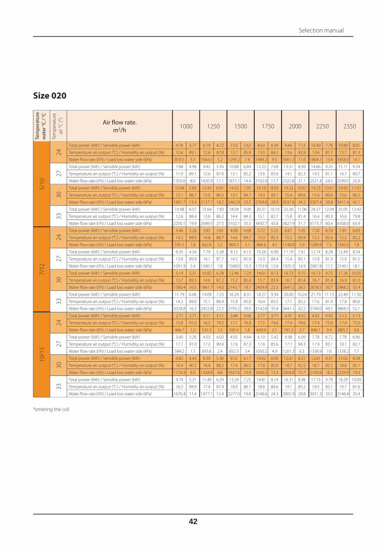
Selection manual
42
Tem
pera
ture
wat
er °C
/ °C
Tem
pe
ratu
re
air
°C
(*) Air fl ow rate.
m3/h 1000 1250 1500 1750 2000 2250 2350
5/1
0
24
Total power (kW) / Sensible power (kW) 4.76 3.77 6.19 4.72 7.53 5.62 8.63 6.39 9.66 7.13 10.49 7.76 10.80 8.01
Temperature air output (°C) / Humidity air output (%) 12.6 89.1 12.6 87.8 12.7 85.8 13.0 84.2 13.6 82.9 13.6 81.7 13.7 81.3
Water fl ow rate (l/h) / Load loss water side (kPa) 818.5 3.3 1064.5 5.2 1295.2 7.4 1484.2 9.5 1661.3 11.6 1804.1 13.4 1858.0 14.1
27
Total power (kW) / Sensible power (kW) 7.88 4.96 9.42 5.93 10.88 6.84 12.23 7.69 13.51 8.50 14.66 9.25 15.11 9.54
Temperature air output (°C) / Humidity air output (%) 11.9 89.1 12.6 87.0 13.1 85.2 13.6 83.6 14.1 82.3 14.5 81.1 14.7 80.7
Water fl ow rate (l/h) / Load loss water side (kPa) 1355.6 8.0 1620.9 11.1 1871.1 14.4 2102.9 17.7 2322.8 21.1 2521.4 24.5 2599.5 25.9
30
Total power (kW) / Sensible power (kW) 10.48 5.83 12.43 6.91 14.32 7.95 16.10 8.93 19.23 10.67 19.23 10.67 19.83 11.01
Temperature air output (°C) / Humidity air output (%) 12.1 88.7 13.0 86.5 13.7 84.7 14.3 83.1 15.4 80.6 15.4 80.6 15.6 80.2
Water fl ow rate (l/h) / Load loss water side (kPa) 1801.7 13.4 2137.7 18.2 2462.8 23.5 2769.6 28.9 3037.6 34.2 3307.4 39.8 3411.4 42.1
33
Total power (kW) / Sensible power (kW) 13.08 6.57 15.64 7.83 18.04 9.00 20.31 10.10 22.26 11.06 24.27 12.04 25.05 12.42
Temperature air output (°C) / Humidity air output (%) 12.6 88.4 13.6 86.2 14.4 84.3 15.1 82.7 15.8 81.4 16.4 80.3 16.6 79.8
Water fl ow rate (l/h) / Load loss water side (kPa) 2250.1 19.9 2689.5 27.5 3102.1 35.5 3492.7 43.8 3827.9 51.7 4173.7 60.4 4308.0 63.9
7/1
2
24
Total power (kW) / Sensible power (kW) 3.46 3.26 3.85 3.81 4.68 4.68 5.72 5.25 6.67 5.95 7.50 6.59 7.81 6.83
Temperature air output (°C) / Humidity air output (%) 14.2 89.9 14.8 88.7 14.6 89.7 15.0 85.3 15.2 83.9 15.2 82.6 15.2 82.2
Water fl ow rate (l/h) / Load loss water side (kPa) 595.5 1.8 662.6 2.2 804.3 3.1 984.6 4.5 1148.0 5.9 1289.9 7.3 1343.0 7.8
27
Total power (kW) / Sensible power (kW) 6.35 4.34 7.79 5.28 9.12 6.15 10.20 6.90 11.19 7.61 12.14 8.28 12.49 8.54
Temperature air output (°C) / Humidity air output (%) 13.8 89.9 14.1 87.7 14.5 85.9 15.0 84.4 15.4 83.1 15.8 81.9 15.9 81.5
Water fl ow rate (l/h) / Load loss water side (kPa) 1091.9 5.4 1340.7 7.8 1568.0 10.3 1753.9 12.6 1925.5 14.9 2087.8 17.2 2149.1 18.1
30
Total power (kW) / Sensible power (kW) 9.19 5.31 10.82 6.28 12.46 7.23 14.01 8.13 16.73 9.75 16.73 9.75 17.26 10.05
Temperature air output (°C) / Humidity air output (%) 13.7 89.3 14.6 87.2 15.2 85.4 15.7 83.9 16.7 81.4 16.7 81.4 16.9 81.0
Water fl ow rate (l/h) / Load loss water side (kPa) 1580.4 10.5 1861.7 14.0 2143.7 18.1 2409.9 22.3 2647.5 26.5 2878.5 30.7 2968.2 32.4
33
Total power (kW) / Sensible power (kW) 11.79 6.06 14.09 7.23 16.24 8.31 18.27 9.34 20.00 10.24 21.79 11.15 22.49 11.50
Temperature air output (°C) / Humidity air output (%) 14.2 89.0 15.1 86.9 15.8 85.0 16.4 83.5 17.1 82.2 17.6 81.0 17.8 80.6
Water fl ow rate (l/h) / Load loss water side (kPa) 2028.8 16.3 2422.8 22.5 2793.2 29.0 3142.6 35.8 3441.1 42.2 3749.0 49.2 3868.5 52.1
10
/15
24
Total power (kW) / Sensible power (kW) 2.71 2.71 3.11 3.11 3.46 3.46 3.77 3.77 4.31 4.31 4.92 4.92 5.13 5.13
Temperature air output (°C) / Humidity air output (%) 15.8 91.0 16.5 79.5 17.1 76.8 17.5 74.6 17.4 74.6 17.4 75.0 17.4 75.0
Water fl ow rate (l/h) / Load loss water side (kPa) 466.7 1.2 535.3 1.5 595.4 1.8 649.4 2.1 741.2 2.7 846.1 3.4 883.2 3.6
27
Total power (kW) / Sensible power (kW) 3.40 3.26 4.03 4.03 4.95 4.64 6.10 5.42 6.98 6.09 7.78 6.72 7.78 6.86
Temperature air output (°C) / Humidity air output (%) 17.1 91.0 17.2 90.9 17.6 87.3 17.6 85.6 17.7 84.3 17.9 83.1 18.1 82.7
Water fl ow rate (l/h) / Load loss water side (kPa) 584.2 1.7 693.6 2.4 852.3 3.4 1050.2 4.9 1201.3 6.3 1338.9 7.6 1338.2 7.7
30
Total power (kW) / Sensible power (kW) 6.82 4.43 8.30 5.36 9.52 6.17 10.62 6.92 12.61 8.31 12.61 8.31 13.02 8.58
Temperature air output (°C) / Humidity air output (%) 16.4 90.3 16.8 88.2 17.4 86.5 17.8 85.0 18.7 82.5 18.7 82.5 18.8 82.1
Water fl ow rate (l/h) / Load loss water side (kPa) 1174.3 6.0 1428.8 8.6 1637.6 10.9 1826.5 13.3 2004.8 15.7 2169.8 18.2 2239.9 19.3
33
Total power (kW) / Sensible power (kW) 9.74 5.31 11.49 6.29 13.24 7.25 14.81 8.14 16.31 8.98 17.73 9.78 18.29 10.09
Temperature air output (°C) / Humidity air output (%) 16.5 89.9 17.4 87.9 18.0 86.1 18.6 84.6 19.1 83.2 19.5 82.1 19.7 81.6
Water fl ow rate (l/h) / Load loss water side (kPa) 1676.4 11.4 1977.1 15.4 2277.0 19.8 2548.6 24.3 2805.9 28.8 3051.3 33.5 3146.4 35.4
Size 020
*entering the coil

Selection manual
43
Tem
pera
ture
wat
er °C
/ °C
Tem
pe
ratu
re
air
°C
(*) Air fl ow rate.
m3/h 1500 1900 2300 2700 3000 3300 3500
5/1
0
24
Total power (kW) / Sensible power (kW) 9.12 6.81 10.67 8.12 12.03 9.30 13.24 10.37 14.08 11.12 14.85 11.82 15.20 12.21
Temperature air output (°C) / Humidity air output (%) 10.3 96.5 11.1 94.5 11.8 92.3 12.4 90.3 13.2 88.9 13.2 87.5 13.5 86.7
Water fl ow rate (l/h) / Load loss water side (kPa) 1568.9 3.9 1835.3 5.2 2069.1 6.4 2278.0 7.7 2421.3 8.5 2554.9 9.4 2614.7 9.8
27
Total power (kW) / Sensible power (kW) 12.86 8.22 15.18 9.81 17.24 11.23 19.08 12.53 20.38 13.43 21.61 14.29 22.38 14.83
Temperature air output (°C) / Humidity air output (%) 10.3 96.5 11.3 94.2 12.1 92.0 12.9 89.9 13.4 88.4 13.8 87.0 14.1 86.2
Water fl ow rate (l/h) / Load loss water side (kPa) 2211.7 7.3 2611.0 9.8 2964.3 12.3 3282.3 14.8 3505.3 16.6 3716.2 18.5 3849.4 19.7
30
Total power (kW) / Sensible power (kW) 16.82 9.56 20.07 11.45 22.94 13.13 25.51 14.64 28.97 16.67 28.97 16.67 30.03 17.30
Temperature air output (°C) / Humidity air output (%) 10.4 96.3 11.5 94.0 12.5 91.7 13.3 89.5 14.5 86.6 14.5 86.6 14.8 85.8
Water fl ow rate (l/h) / Load loss water side (kPa) 2892.7 11.8 3451.7 16.2 3946.1 20.7 4387.9 25.0 4694 28.2 4982.7 31.4 5165.8 33.5
33
Total power (kW) / Sensible power (kW) 21.27 10.92 25.49 13.07 29.15 14.95 32.55 16.67 34.89 17.86 37.11 18.98 38.52 19.70
Temperature air output (°C) / Humidity air output (%) 10.4 96.2 11.7 93.8 12.8 91.5 13.8 89.3 14.5 87.7 15.1 86.3 15.5 85.4
Water fl ow rate (l/h) / Load loss water side (kPa) 3658.9 18.0 4383.8 24.8 5013.2 31.8 5597.5 38.8 6001.5 43.9 6382.7 49.0 6624.9 52.4
7/1
2
24
Total power (kW) / Sensible power (kW) 5.86 5.47 7.48 6.83 8.23 7.78 9.13 8.75 10.15 9.58 10.67 10.19 11.00 10.58
Temperature air output (°C) / Humidity air output (%) 13.0 96.8 13.2 94.9 13.8 92.9 14.2 90.9 14.7 89.5 14.7 88.2 14.9 87.3
Water fl ow rate (l/h) / Load loss water side (kPa) 1008.4 1.8 1287.4 2.7 1415.6 3.2 1571.1 3.9 1746.7 4.7 1836.1 5.1 1892.3 5.4
27
Total power (kW) / Sensible power (kW) 10.59 7.28 12.43 8.69 14.05 9.97 15.50 11.13 16.49 11.93 17.35 12.66 17.96 13.15
Temperature air output (°C) / Humidity air output (%) 12.2 96.8 13.1 94.6 13.8 92.5 14.5 90.5 14.9 89.0 15.3 87.7 15.6 86.9
Water fl ow rate (l/h) / Load loss water side (kPa) 1822.6 5.1 2137.4 6.8 2416.4 8.4 2666.0 10.1 2836.6 11.2 2985.0 12.3 3088.7 13.1
30
Total power (kW) / Sensible power (kW) 14.68 8.67 17.37 10.36 19.76 11.88 21.97 13.27 24.85 15.13 24.85 15.13 25.74 15.70
Temperature air output (°C) / Humidity air output (%) 12.2 96.6 13.2 94.4 14.1 92.2 14.9 90.1 15.9 87.3 15.9 87.3 16.2 86.4
Water fl ow rate (l/h) / Load loss water side (kPa) 2525.4 9.1 2988.2 12.3 3399.7 15.6 3778.8 18.9 4040.5 21.3 4273.9 23.6 4426.8 25.1
33
Total power (kW) / Sensible power (kW) 19.09 10.01 22.81 12.00 26.05 13.74 29.02 15.34 31.08 16.45 33.02 17.49 34.24 18.15
Temperature air output (°C) / Humidity air output (%) 12.3 96.5 13.4 94.2 14.5 92.0 15.4 89.9 16.0 88.4 16.6 87.0 16.9 86.1
Water fl ow rate (l/h) / Load loss water side (kPa) 3283.9 14.6 3924.1 20.1 4480.7 25.7 4991.3 31.1 5345.9 35.2 5679.1 39.3 5890.6 42.0
10
/15
24
Total power (kW) / Sensible power (kW) 4.22 4.22 5.34 5.34 6.29 6.29 7.12 7.12 7.71 7.71 8.19 8.19 8.48 8.48
Temperature air output (°C) / Humidity air output (%) 15.5 97.3 15.5 84.6 15.8 83.3 16.1 81.8 16.5 80.7 16.5 79.4 16.7 78.5
Water fl ow rate (l/h) / Load loss water side (kPa) 726.8 1.0 919.1 1.5 1081.6 2.0 1225.7 2.5 1326.0 2.8 1409.1 3.1 1458.4 3.3
27
Total power (kW) / Sensible power (kW) 6.19 5.62 7.75 6.95 8.17 7.82 9.54 8.97 10.09 9.64 10.60 10.26 10.92 10.66
Temperature air output (°C) / Humidity air output (%) 15.6 97.3 15.9 95.3 16.7 93.3 16.9 91.3 17.2 89.9 17.5 88.6 17.7 87.8
Water fl ow rate (l/h) / Load loss water side (kPa) 1065.4 1.9 1333.9 2.8 1406.3 3.1 1642.1 4.1 1736.9 4.6 1824.3 5.0 1879.2 5.3
30
Total power (kW) / Sensible power (kW) 11.01 7.27 12.91 8.70 14.58 10.00 16.08 11.17 18.01 12.74 18.01 12.74 18.64 13.24
Temperature air output (°C) / Humidity air output (%) 15.1 97.1 15.9 95.0 16.6 92.9 17.3 90.9 18.1 88.2 18.1 88.2 18.4 87.4
Water fl ow rate (l/h) / Load loss water side (kPa) 1894.5 5.3 2221.0 7.1 2509.2 8.9 2767.3 10.6 2929.1 11.7 3099.1 12.9 3206.8 13.8
33
Total power (kW) / Sensible power (kW) 15.54 8.66 18.38 10.36 20.96 11.91 23.28 13.32 24.82 14.28 26.31 15.20 27.25 15.78
Temperature air output (°C) / Humidity air output (%) 15.1 97.0 16.1 94.9 16.9 92.7 17.7 90.7 18.2 89.2 18.7 87.9 19.0 87.0
Water fl ow rate (l/h) / Load loss water side (kPa) 2674.4 9.9 3161.6 13.4 3606.4 17.0 4005.8 20.6 4270.8 23.1 4526.7 25.7 4688.9 27.4
Size 031
*entering the coil

Selection manual
44
Tem
pera
ture
wat
er °C
/ °C
Tem
pe
ratu
re
air
°C
(*) Air fl ow rate.
m3/h 2200 2700 3200 3700 4000 4200 4600
5/1
0
24
Total power (kW) / Sensible power (kW) 13.36 9.92 15.28 11.52 17.00 12.98 18.55 14.31 19.41 15.06 19.95 15.54 20.91 16.43
Temperature air output (°C) / Humidity air output (%) 10.4 95.5 11.1 93.6 11.8 91.6 12.3 89.7 12.9 88.6 12.9 87.9 13.2 86.6
Water fl ow rate (l/h) / Load loss water side (kPa) 2297.0 5.5 2627.8 7.0 2923.1 8.5 3190.0 10.0 3338.6 10.8 3432.1 11.3 3596.9 12.3
27
Total power (kW) / Sensible power (kW) 18.73 11.94 21.59 13.87 24.17 15.64 26.55 17.26 27.89 18.17 28.69 18.74 30.27 19.84
Temperature air output (°C) / Humidity air output (%) 10.5 95.5 11.4 93.3 12.1 91.2 12.8 89.3 13.2 88.2 13.4 87.5 13.9 86.1
Water fl ow rate (l/h) / Load loss water side (kPa) 3220.9 10.1 3712.7 13.1 4157.4 16.1 4566.7 19.1 4796.5 20.8 4933.9 21.9 5206.6 24.1
30
Total power (kW) / Sensible power (kW) 24.53 13.90 28.44 16.16 31.99 18.22 35.22 20.09 38.20 21.82 38.20 21.82 40.42 23.11
Temperature air output (°C) / Humidity air output (%) 10.6 95.3 11.6 93.1 12.5 90.9 13.3 88.9 14.0 87.1 14.0 87.1 14.6 85.7
Water fl ow rate (l/h) / Load loss water side (kPa) 4218.7 16.4 4892.0 21.6 5502.2 26.7 6057.5 31.7 6369.8 34.7 6569.9 36.7 6952.6 40.6
33
Total power (kW) / Sensible power (kW) 30.93 15.83 35.93 18.38 40.55 20.72 44.78 22.84 47.16 24.04 48.69 24.80 51.61 26.27
Temperature air output (°C) / Humidity air output (%) 10.7 95.1 11.9 92.9 12.9 90.7 13.8 88.6 14.4 87.5 14.7 86.8 15.3 85.4
Water fl ow rate (l/h) / Load loss water side (kPa) 5320.5 25.0 6179.1 32.9 6974.4 40.9 7701.7 48.8 8111.2 53.5 8373.9 56.7 8876.9 63.0
7/1
2
24
Total power (kW) / Sensible power (kW) 9.85 8.46 11.34 9.91 12.53 11.18 13.10 12.15 13.71 12.82 14.10 13.24 15.27 14.22
Temperature air output (°C) / Humidity air output (%) 12.4 95.8 12.9 94.1 13.5 92.1 14.1 90.4 14.5 89.3 14.5 88.6 14.7 87.3
Water fl ow rate (l/h) / Load loss water side (kPa) 1694.1 3.2 1950.4 4.1 2154.6 4.9 2253.6 5.3 2359.0 5.7 2426.2 6.0 2627.4 6.9
27
Total power (kW) / Sensible power (kW) 15.48 10.59 17.75 12.32 19.79 13.89 21.57 15.31 22.62 16.13 23.30 16.65 24.59 17.66
Temperature air output (°C) / Humidity air output (%) 12.4 95.8 13.1 93.8 13.8 91.8 14.4 89.9 14.7 88.8 14.9 88.1 15.3 86.8
Water fl ow rate (l/h) / Load loss water side (kPa) 2662.8 7.1 3053.8 9.1 3404.1 11.0 3710.5 12.9 3891.8 14.1 4007.8 14.8 4229.7 16.3
30
Total power (kW) / Sensible power (kW) 21.28 12.55 24.69 14.65 27.68 16.52 30.41 18.23 32.91 19.81 32.91 19.81 34.78 20.99
Temperature air output (°C) / Humidity air output (%) 12.5 95.7 13.3 93.5 14.1 91.5 14.9 89.5 15.5 87.7 15.5 87.7 16.0 86.4
Water fl ow rate (l/h) / Load loss water side (kPa) 3660.7 12.7 4247.4 16.5 4762.1 20.3 5230.2 24.0 5493.1 26.3 5661.5 27.7 5983.0 30.6
33
Total power (kW) / Sensible power (kW) 27.81 14.54 32.23 16.90 36.30 19.06 40.02 21.04 42.11 22.15 43.45 22.86 46.01 24.22
Temperature air output (°C) / Humidity air output (%) 12.5 95.5 13.6 93.3 14.5 91.2 15.4 89.2 15.8 88.1 16.1 87.4 16.7 86.1
Water fl ow rate (l/h) / Load loss water side (kPa) 4783.2 20.4 5544.6 26.7 6243.6 33.0 6883.7 39.4 7243.2 43.2 7473.7 45.7 7914.6 50.7
10
/15
24
Total power (kW) / Sensible power (kW) 6.68 6.68 7.97 7.97 9.12 9.12 10.06 10.06 10.56 10.56 10.87 10.87 11.48 11.48
Temperature air output (°C) / Humidity air output (%) 14.9 96.4 15.1 86.9 15.4 85.2 15.8 83.1 16.2 81.8 16.2 81.0 16.5 79.6
Water fl ow rate (l/h) / Load loss water side (kPa) 1149.6 1.6 1372.1 2.1 1569.3 2.7 1731.7 3.2 1816.7 3.5 1871.1 3.7 1974.9 4.1
27
Total power (kW) / Sensible power (kW) 10.02 8.51 11.34 9.92 11.90 11.00 13.56 12.40 14.14 13.06 14.51 13.49 15.21 14.32
Temperature air output (°C) / Humidity air output (%) 15.2 96.4 15.8 94.5 16.5 92.6 16.8 90.7 17.1 89.7 17.2 89.0 17.5 87.8
Water fl ow rate (l/h) / Load loss water side (kPa) 1724.1 3.2 1951.8 4.0 2046.9 4.3 2333.5 5.5 2433.5 5.9 2497.0 6.2 2617.7 6.8
30
Total power (kW) / Sensible power (kW) 16.09 10.58 18.45 12.33 20.56 13.92 22.42 15.37 24.22 16.74 24.22 16.74 25.55 17.77
Temperature air output (°C) / Humidity air output (%) 15.2 96.2 16.0 94.2 16.6 92.3 17.2 90.4 17.8 88.6 17.8 88.6 18.1 87.3
Water fl ow rate (l/h) / Load loss water side (kPa) 2769.2 7.5 3174.3 9.6 3537.1 11.6 3857.2 13.6 4045.6 14.8 4167.6 15.7 4396.5 17.3
33
Total power (kW) / Sensible power (kW) 22.57 12.55 26.16 14.66 29.32 16.55 32.20 18.28 33.82 19.26 34.86 19.89 36.84 21.09
Temperature air output (°C) / Humidity air output (%) 15.3 96.1 16.2 94.0 17.0 92.0 17.7 90.1 18.1 89.0 18.3 88.3 18.8 87.0
Water fl ow rate (l/h) / Load loss water side (kPa) 3883.3 13.8 4500.6 18.0 5045.0 22.2 5540.1 26.2 5818.8 28.7 5997.2 30.3 6338.2 33.5
Size 042
*entering the coil

Notes

Notes

Notes

I dati tecnici riportati sulla seguente documentazione non sono impegnativi. FAST si riserva la facoltà di apportare in qualsiasi momento tutte le modifiche ritenute necessarie per il miglioramento del prodotto
FAST S.p.A. TRATTAMENTO DELL'ARIA35044 Montagnana (PD) - ItalyVia Luppia Alberi, 170Tel. (+39) 0429 806311 - Fax 0429 806340E-mail: [email protected]://www.fastaer.com
Carta reciclata
Recycled paper
Recyclingpapier
Papier recyclé
Papel reciclado
Les caractéristiques techniques figurant dans la documentation suivante ne sont pas contractuelles. La société Fast se réserve la faculté d’apporter à tout moment toutes les modifications estimées nécessaires pour l’amélioration du produit.
Die technischen Daten in der folgenden Dokumente sind nicht bindend. FAST behält sich das Recht vor, jederzeit Änderungen als notwendig für die Verbesserung der Produkt.
Technical data shown in this booklet are not binding. FAST S.p.A. shall have the right to introduce at any time whatever modifi cations deemed necessa-ry to the improvement of the product.
Los datos técnicos indicados en la siguiente documentación no son vin-culantes. FAST se reserva el derecho de introducir, en cualquier momento, todas las modifi caciones que retenga necesarias paramejorar el producto.


