
Journal of Advanced Research in Applied Mechanics 41, Issue 1 (2018) 16-21
16
Journal of Advanced Research in
Applied Mechanics
Journal homepage: www.akademiabaru.com/aram.html
ISSN: 2289-7895
High Gain and Radiation Efficiency Rectangular on-Chip
Microstrip Patch Antenna for 60 GHz Applications
S. Abdelhamied1,∗
, H. A. Malhat1, S. H. Zainud-Deen
1
1 Department of Electronics and Electrical Engineering, Faculty of Electronic Engineering, Menoufia University, Egypt
ARTICLE INFO ABSTRACT
Article history:
Received 5 June 2017
Received in revised form 10 July 2017
Accepted 4 December 2017
Available online 12 March 2018
This paper introduces the design of the X-shaped unit-cell artificial magnetic
conductor for rectangular on-chip microstrip patch antenna. The antenna with 50 Ω
CPW for 60 GHz applications is proposed. The radiation characteristics of the antenna
are analyzed and simulated using the finite integration technique, FIT. An X-shaped
AMC plane is utilized as an electromagnetic shield beneath the on-chip patch antenna
for gain and radiation efficiency enhancement. Different configurations of the AMC
planes are employed, full plane, 10×10 AMC units removed blank plane, 6×7 AMC
units removed blank plane, and 4×5 AMC units removed blank plane. The full AMC
plane introduces gain enhancement of 1.15 dBi and radiation efficiency improvement
of 10 % compared to that without AMC case. A depletion layer is employed for more
enhancements in the performance of the on-chip patch antenna. This procedure
boosts the gain and the radiation efficiency to 4.2 dBi and 79 % respectively.
Keywords:
On-chip antenna, artificial magnetic
conductor, FIT, depletion layer Copyright © 2018 PENERBIT AKADEMIA BARU - All rights reserved
1. Introduction
Lately, an interest in millimeter-wave communication is enhanced due to their high data rates.
The unlicensed frequency band at 60 GHz has become a potential candidate for short range
communication as it is characterized by high attenuation due to atmospheric absorption [1].
Different applications such as uncompressed high definition video streaming, mobile distributed
computing, and wireless gaming are prospected. Antenna-on-Chip (AoC) is an emerging technology
that guarantees the integration of the antennas, radio frequency circuits and digital circuits on the
same chip, allowing the implementation of System-on-Chip (SoC) [2]. The progress of the low-cost
Complementary Metal Oxide Semiconductor (CMOS) technology has facilitated the mass
production of 60-GHz such circuits [3]. Several CMOS on-chip antennas have been introduced to
satisfy the demands of the 60 GHz SoC [4]. Losses due to the high permittivity and low resistivity
CMOS substrate lead to performance degradation of the AoC in terms of gain and radiation
efficiency. Different techniques are employed to improve the gain and radiation efficiency of AoC,
such as proton implantation and micro-machining [5-6]. But these techniques are expensive,
∗
Corresponding author.
E-mail address: s_abdelhamied @yahoo.com (S. Abdelhamied)
Penerbit
Akademia Baru
Open
Access
Journal of Advanced Research in Applied Mechanics
Volume 41, Issue 1 (2018) 16-21
17
Penerbit
Akademia Baru
complex, not compatible with the mainstream CMOS process and reduce the level of the system
integration. An efficient technique is employed by inserting EM shielding plane between the
antenna and the lossy CMOS substrate using the periodic structure of Artificial Magnetic Conductor
(AMC) cells [7].
This technique will minimize the substrate losses and reduce back radiation while maintaining
the cost and system level integration. AMC behaves like the perfect magnetic conductor (PMC),
where the reflection coefficient is +1 and the reflected wave can constructively enhance the entire
electromagnetic field. A wideband patch AoC with two parasitic strips and a snowflake AMC as a
shield is introduced in [8]. A triangular patch AoC over Jerusalem-Cross (JC) AMC [9] introduces a
gain of 0 dBi and radiation efficiency of 39%, respectively. Different AMC structures used as EM
shielding for AoC systems have been introduced to gain and radiation efficiency enhancement [10].
In this paper, the radiation characteristics of on-chip patch antenna have improved by using an
X-shape AMC structures. The AoC and AMC are designed using 0.18um CMOS process. For all
configurations, both the AMC and the AoC are optimized to cover the 60-GHz wide bandwidth
(from 57 to 64 GHz). A depletion layer with high resistivity is inserted into the lossy CMOS substrate
below the AMC plane to reduce the substrate losses. The finite integration technique (FIT) [11] is
employed to analyze the antenna structure and the results are verified by using finite element
method (FEM) [12]. The paper is organized as follows: Section 2.1 introduces the design of the
proposed on-chip patch antenna and its radiation characteristics. Section 2.2 presents the proposed
X-shape AMC’s unit-cell design and reflection coefficient response in addition to introducing the
radiation characteristics of the AoC in the presence of different configurations of X-shape AMC
plane. Section 2.3 discusses the implementation of a depletion layer into the silicon substrate for
more improvements. Finally, the results are concluded in Section 3.
2. Numerical Results
2.1 O-Chip Patch Antenna Design
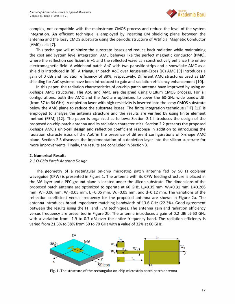
The geometry of a rectangular on-chip microstrip patch antenna fed by 50 Ω coplanar
waveguide (CPW) is presented in Figure 1. The antenna with its CPW feeding structure is placed in
the M6 layer and a PEC ground plane is located under the silicon substrate. The dimensions of the
proposed patch antenna are optimized to operate at 60 GHz, Lp=0.35 mm, Wp=0.31 mm, Lf=0.266
mm, Wf=0.06 mm, Wt=0.05 mm, Lc=0.05 mm, Wc=0.05 mm, and d=0.12 mm. The variations of the
reflection coefficient versus frequency for the proposed antenna are shown in Figure 2a. The
antenna introduces broad impedance matching bandwidth of 13.6 GHz (22.3%). Good agreement
between the results using the FIT and FEM techniques. The antenna gain and radiation efficiency
versus frequency are presented in Figure 2b. The antenna introduces a gain of 0.2 dBi at 60 GHz
with a variation from -1.9 to 0.7 dBi over the entire frequency band. The radiation efficiency is
varied from 21.5% to 38% from 50 to 70 GHz with a value of 32% at 60 GHz.
Fig. 1. The structure of the rectangular on-chip microstrip patch patch antenna

Journal of Advanced Research in Applied Mechanics
Volume 41, Issue 1 (2018) 16-21
18
Penerbit
Akademia Baru
Fig. 2. (a) The reflection coefficient response of the on-chip patch antenna, (b) The
responses of gain and radiation efficiency of the on-chip microstrip patch antena
Fig. 3. (a) The Cross-section view of a 0.18um CMOS process with six metal
layers over the silicon substrate. b, and c. The geometry of the X-shape
AMC unit cell
2.2 On-Chip Antenna Design over AMC Plane
The detailed structure of the on-chip X-shape AMC unit-cell using the 0.18µm CMOS technology
is shown in Figure 3a. The 0.18µm CMOS technology consists of six metal layers (M1 to M6) isolated
from each other by insulator layers of SiO2 with thickness 22 µm and relative dielectric constant
εri=3.9 printed over a silicon substrate with thickness 0.29 mm, relative dielectric constant εrs=11.9,
and conductivity σ=10 S/m. The top metal layer (M6) is assigned for the antenna fabrication and it
is thicker than the other layers to guarantee a reduction in the conduction losses, while the bottom
metal layer (M1) is utilized for the AMC structure. The configuration of the proposed X-shape on-
chip AMC unit-cell is shown in Figures 3b, and 3c. The dimensions of the X-shape AMC unit-cell are
Lc= 0.15 mm, Wc= 10 µm, and G=11.5 µm. The dimensions are optimized to operate at 60 GHz.
Perfect-E and perfect-H boundary conditions are used to realize the periodic boundary conditions
(PBCs) to calculate the reflection response of the AMC unit-cell. The wave port is used as excitation
port and is embedded into the surface of the AMC unit-cell as shown in Figure 4a. The variations of
the reflection coefficient phase versus frequency of the proposed X-shape AMC unit-cell are
presented in Figure 4b. It demonstrates a reflection phase of 0 degree at 60 GHz with ±90º
bandwidth of 13.8 GHz (53~66.8 GHz) with a share of 23 %. The proposed AMC unit-cell covers the
intended unlicensed band (57~64 GHz). The results are calculated using the FIT and FEM. Good
agreement is depicted.
An X-shape AMC surface is realized in M1 layer beneath the antenna as shown in Figure 5.
Different configurations of the AMC unit-cell are employed, full plane, 10×10 AMC units removed
blank plane, 6×7 AMC units removed blank plane, and 4×5 AMC units removed blank plane are
employed. The dimensions of the microstrip patch antenna are optimized in each geometry in
order to keep the resonance frequency at 60 GHz. The impedance bandwidth of the full AMC plane
case extends from 44 GHz to 93 GHz (81 %). The optimized dimensions of the proposed antennas

Journal of Advanced Research in Applied Mechanics
Volume 41, Issue 1 (2018) 16-21
19
Penerbit
Akademia Baru
with different forms of AMC plane are listed in Table 1. The responses of the antenna gain and the
radiation efficiency are shown in Figure 6. The full AMC configuration offers the highest gain and
radiation efficiency of 1.2 dBi, and 42% respectively. An improvement in antenna gain of 1.15 dBi
and 10 % in radiation efficiency compared to the antenna performance without the AMC plane.
Fig. 4. (a) Simulation model for an AMC cell. (b) The variation of the reflection phase versus
frequency of the proposed AMC unit cell
Fig. 5. Simulation models for the on-chip antenna with (a) full AMC plane, and (b) 10x10
AMC units blank, 6×7 AMC units blank and 4×5 AMC units blank
Table 1
The optimized dimensions of the antennas for different AMC planes
Antenna
dimensions
(mm)
Antenna
without AMC
On-chip antenna with AMC
10x10 blank 6x7 blank 4x5 blank Full AMC
Lp 0.35 0.35 0.38 0.4 0.55
Wp 0.31 0.31 0.335 0.32 0.5
Lf 0.266 0.266 0.266 0.266 0.3
Lc 0.05 0.05 0.05 0.05 0.08
Wc 0.05 0.05 0.05 0.05 0.08
Wt 0.05 0.05 0.05 0.05 0.05
Wf 0.06 0.06 0.06 0.06 0.06
d 0.12 0.12 0.12 0.12 0.12
Fig. 6. The variation of the gain and radiation efficiency versus frequency
for the proposed on-chip patch antenna with the different structures of
the AMC planes
Journal of Advanced Research in Applied Mechanics
Volume 41, Issue 1 (2018) 16-21
20
Penerbit
Akademia Baru
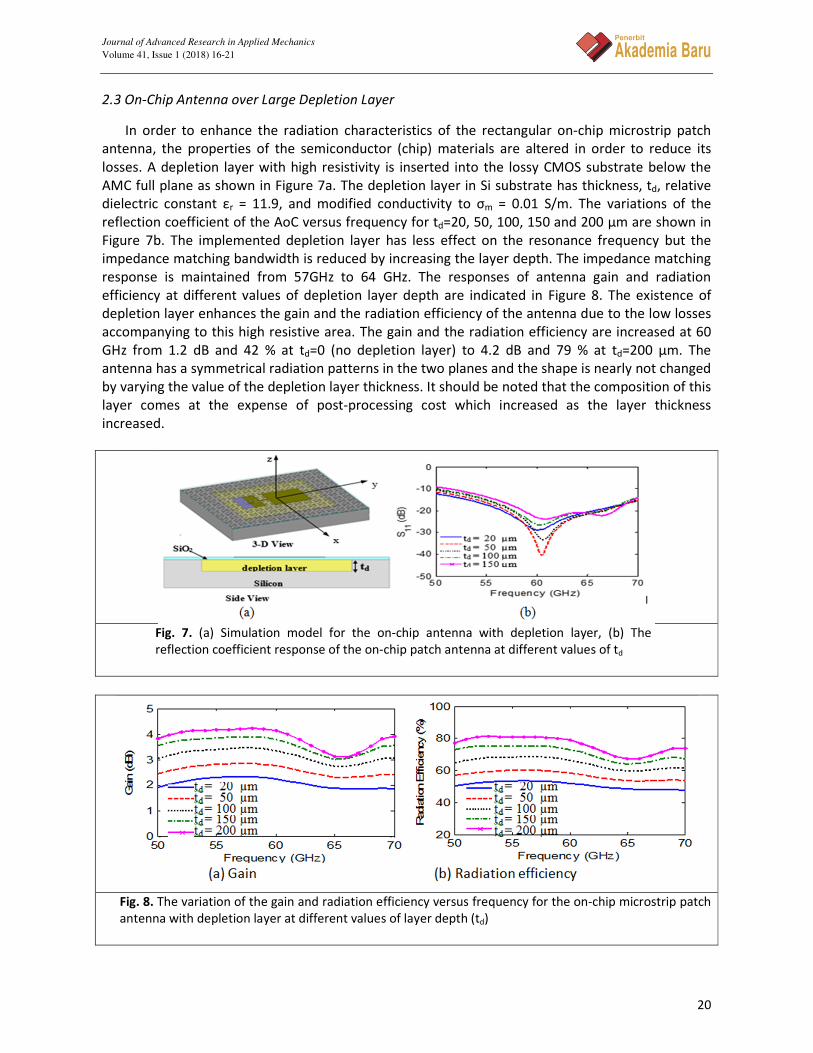
2.3 On-Chip Antenna over Large Depletion Layer
In order to enhance the radiation characteristics of the rectangular on-chip microstrip patch
antenna, the properties of the semiconductor (chip) materials are altered in order to reduce its
losses. A depletion layer with high resistivity is inserted into the lossy CMOS substrate below the
AMC full plane as shown in Figure 7a. The depletion layer in Si substrate has thickness, td, relative
dielectric constant εr = 11.9, and modified conductivity to σm = 0.01 S/m. The variations of the
reflection coefficient of the AoC versus frequency for td=20, 50, 100, 150 and 200 µm are shown in
Figure 7b. The implemented depletion layer has less effect on the resonance frequency but the
impedance matching bandwidth is reduced by increasing the layer depth. The impedance matching
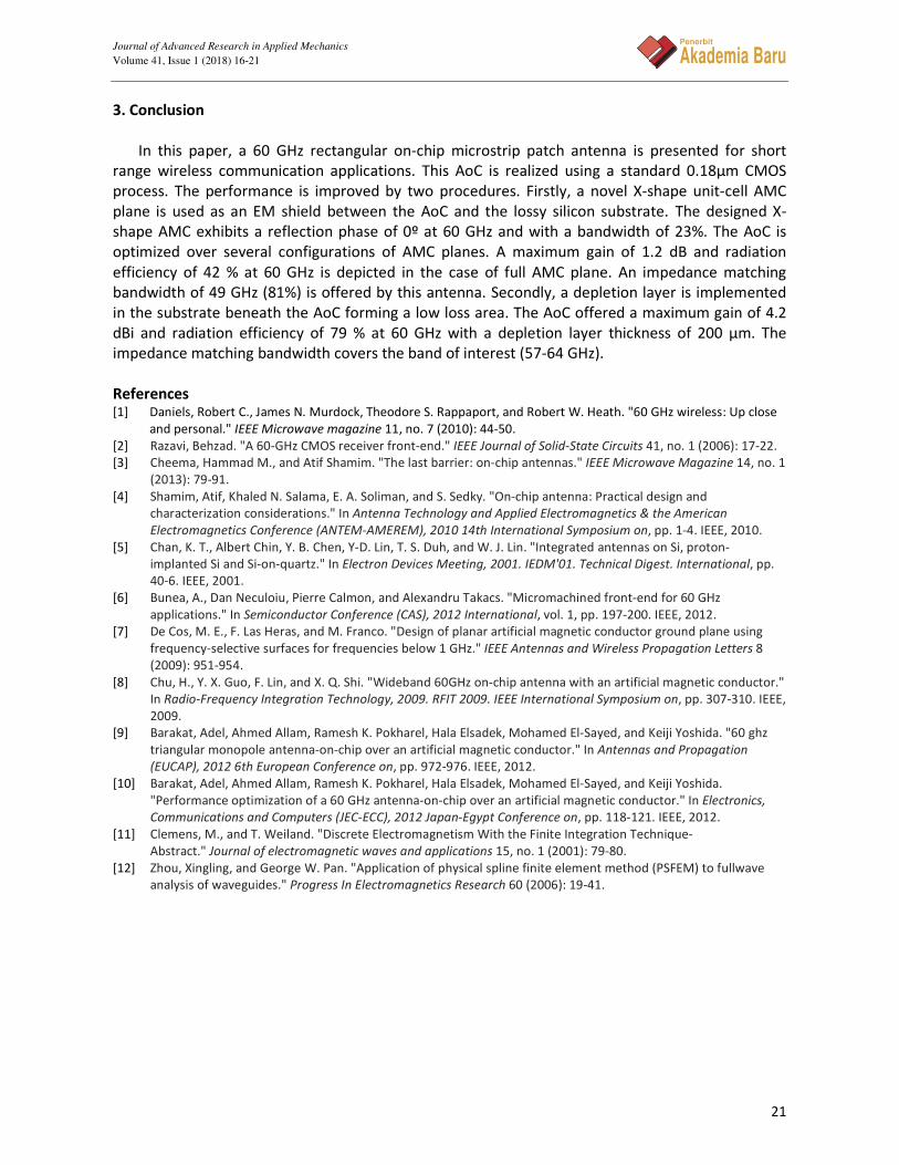
response is maintained from 57GHz to 64 GHz. The responses of antenna gain and radiation
efficiency at different values of depletion layer depth are indicated in Figure 8. The existence of
depletion layer enhances the gain and the radiation efficiency of the antenna due to the low losses
accompanying to this high resistive area. The gain and the radiation efficiency are increased at 60
GHz from 1.2 dB and 42 % at td=0 (no depletion layer) to 4.2 dB and 79 % at td=200 µm. The
antenna has a symmetrical radiation patterns in the two planes and the shape is nearly not changed
by varying the value of the depletion layer thickness. It should be noted that the composition of this
layer comes at the expense of post-processing cost which increased as the layer thickness
increased.
Fig. 7. (a) Simulation model for the on-chip antenna with depletion layer, (b) The
reflection coefficient response of the on-chip patch antenna at different values of td
Fig. 8. The variation of the gain and radiation efficiency versus frequency for the on-chip microstrip patch
antenna with depletion layer at different values of layer depth (td)
Journal of Advanced Research in Applied Mechanics
Volume 41, Issue 1 (2018) 16-21
21
Penerbit
Akademia Baru
3. Conclusion
In this paper, a 60 GHz rectangular on-chip microstrip patch antenna is presented for short
range wireless communication applications. This AoC is realized using a standard 0.18µm CMOS
process. The performance is improved by two procedures. Firstly, a novel X-shape unit-cell AMC
plane is used as an EM shield between the AoC and the lossy silicon substrate. The designed X-
shape AMC exhibits a reflection phase of 0º at 60 GHz and with a bandwidth of 23%. The AoC is
optimized over several configurations of AMC planes. A maximum gain of 1.2 dB and radiation
efficiency of 42 % at 60 GHz is depicted in the case of full AMC plane. An impedance matching
bandwidth of 49 GHz (81%) is offered by this antenna. Secondly, a depletion layer is implemented
in the substrate beneath the AoC forming a low loss area. The AoC offered a maximum gain of 4.2
dBi and radiation efficiency of 79 % at 60 GHz with a depletion layer thickness of 200 µm. The
impedance matching bandwidth covers the band of interest (57-64 GHz).
References [1] Daniels, Robert C., James N. Murdock, Theodore S. Rappaport, and Robert W. Heath. "60 GHz wireless: Up close
and personal." IEEE Microwave magazine 11, no. 7 (2010): 44-50.
[2] Razavi, Behzad. "A 60-GHz CMOS receiver front-end." IEEE Journal of Solid-State Circuits 41, no. 1 (2006): 17-22.
[3] Cheema, Hammad M., and Atif Shamim. "The last barrier: on-chip antennas." IEEE Microwave Magazine 14, no. 1
(2013): 79-91.
[4] Shamim, Atif, Khaled N. Salama, E. A. Soliman, and S. Sedky. "On-chip antenna: Practical design and
characterization considerations." In Antenna Technology and Applied Electromagnetics & the American
Electromagnetics Conference (ANTEM-AMEREM), 2010 14th International Symposium on, pp. 1-4. IEEE, 2010.
[5] Chan, K. T., Albert Chin, Y. B. Chen, Y-D. Lin, T. S. Duh, and W. J. Lin. "Integrated antennas on Si, proton-
implanted Si and Si-on-quartz." In Electron Devices Meeting, 2001. IEDM'01. Technical Digest. International, pp.
40-6. IEEE, 2001.
[6] Bunea, A., Dan Neculoiu, Pierre Calmon, and Alexandru Takacs. "Micromachined front-end for 60 GHz
applications." In Semiconductor Conference (CAS), 2012 International, vol. 1, pp. 197-200. IEEE, 2012.
[7] De Cos, M. E., F. Las Heras, and M. Franco. "Design of planar artificial magnetic conductor ground plane using
frequency-selective surfaces for frequencies below 1 GHz." IEEE Antennas and Wireless Propagation Letters 8
(2009): 951-954.
[8] Chu, H., Y. X. Guo, F. Lin, and X. Q. Shi. "Wideband 60GHz on-chip antenna with an artificial magnetic conductor."
In Radio-Frequency Integration Technology, 2009. RFIT 2009. IEEE International Symposium on, pp. 307-310. IEEE,
2009.
[9] Barakat, Adel, Ahmed Allam, Ramesh K. Pokharel, Hala Elsadek, Mohamed El-Sayed, and Keiji Yoshida. "60 ghz
triangular monopole antenna-on-chip over an artificial magnetic conductor." In Antennas and Propagation
(EUCAP), 2012 6th European Conference on, pp. 972-976. IEEE, 2012.
[10] Barakat, Adel, Ahmed Allam, Ramesh K. Pokharel, Hala Elsadek, Mohamed El-Sayed, and Keiji Yoshida.
"Performance optimization of a 60 GHz antenna-on-chip over an artificial magnetic conductor." In Electronics,
Communications and Computers (JEC-ECC), 2012 Japan-Egypt Conference on, pp. 118-121. IEEE, 2012.
[11] Clemens, M., and T. Weiland. "Discrete Electromagnetism With the Finite Integration Technique-
Abstract." Journal of electromagnetic waves and applications 15, no. 1 (2001): 79-80.
[12] Zhou, Xingling, and George W. Pan. "Application of physical spline finite element method (PSFEM) to fullwave
analysis of waveguides." Progress In Electromagnetics Research 60 (2006): 19-41.


