Hash Function Luffa
Specification
Christophe De CanniereESAT-COSIC, Katholieke Universiteit Leuven
Hisayoshi Sato, Dai WatanabeSystems Development Laboratory, Hitachi, Ltd.
31 October 2008
Copyright c©2008 Hitachi, Ltd. All rights reserved.1
Luffa Specification NIST SHA3 Proposal
Contents
1 Introduction 4
2 Preliminary 52.1 Notations . . . . . . . . . . . . . . . . . . . . . . . . . . . . . 5
2.1.1 Parameters . . . . . . . . . . . . . . . . . . . . . . . . 52.1.2 Symbols . . . . . . . . . . . . . . . . . . . . . . . . . . 6
2.2 Data Structure . . . . . . . . . . . . . . . . . . . . . . . . . . 62.3 Iterations . . . . . . . . . . . . . . . . . . . . . . . . . . . . . 7
3 Chaining 83.1 Message Padding . . . . . . . . . . . . . . . . . . . . . . . . . 83.2 Round Function . . . . . . . . . . . . . . . . . . . . . . . . . . 8
3.2.1 Message Injection Function for w = 3 . . . . . . . . . . 103.2.2 Message Injection Function for w = 4 . . . . . . . . . . 113.2.3 Message Injection Function for w = 5 . . . . . . . . . . 11
3.3 Finalization . . . . . . . . . . . . . . . . . . . . . . . . . . . . 11
4 Non-Linear Permutation 124.1 Outline . . . . . . . . . . . . . . . . . . . . . . . . . . . . . . . 124.2 SubCrumb . . . . . . . . . . . . . . . . . . . . . . . . . . . . . 144.3 MixWord . . . . . . . . . . . . . . . . . . . . . . . . . . . . . . 144.4 AddConstant . . . . . . . . . . . . . . . . . . . . . . . . . . . 154.5 Tweaks . . . . . . . . . . . . . . . . . . . . . . . . . . . . . . . 17
5 Optional Usage 17
A Starting Variables 19
B Constants 19B–1 Initial Values . . . . . . . . . . . . . . . . . . . . . . . . . . . 19B–2 w = 3 . . . . . . . . . . . . . . . . . . . . . . . . . . . . . . . 20B–3 w = 4 . . . . . . . . . . . . . . . . . . . . . . . . . . . . . . . 21B–4 w = 5 . . . . . . . . . . . . . . . . . . . . . . . . . . . . . . . 21
C Test Vectors 22C–1 Luffa-224 . . . . . . . . . . . . . . . . . . . . . . . . . . . . . 22C–2 Luffa-256 . . . . . . . . . . . . . . . . . . . . . . . . . . . . . 22C–3 Luffa-384 . . . . . . . . . . . . . . . . . . . . . . . . . . . . . 22C–4 Luffa-512 . . . . . . . . . . . . . . . . . . . . . . . . . . . . . 23
D Implementations of SubCrumb 23D–1 For Intel R© 686 Processors . . . . . . . . . . . . . . . . . . . . 23
Copyright c©2008 Hitachi, Ltd. All rights reserved.2
Luffa Specification NIST SHA3 Proposal
E Implementations of Message Injection Function MI 24E–1 w = 3 . . . . . . . . . . . . . . . . . . . . . . . . . . . . . . . 24E–2 w = 4 . . . . . . . . . . . . . . . . . . . . . . . . . . . . . . . 25E–3 w = 5 . . . . . . . . . . . . . . . . . . . . . . . . . . . . . . . 26
Copyright c©2008 Hitachi, Ltd. All rights reserved.3
Luffa Specification NIST SHA3 Proposal
1 Introduction
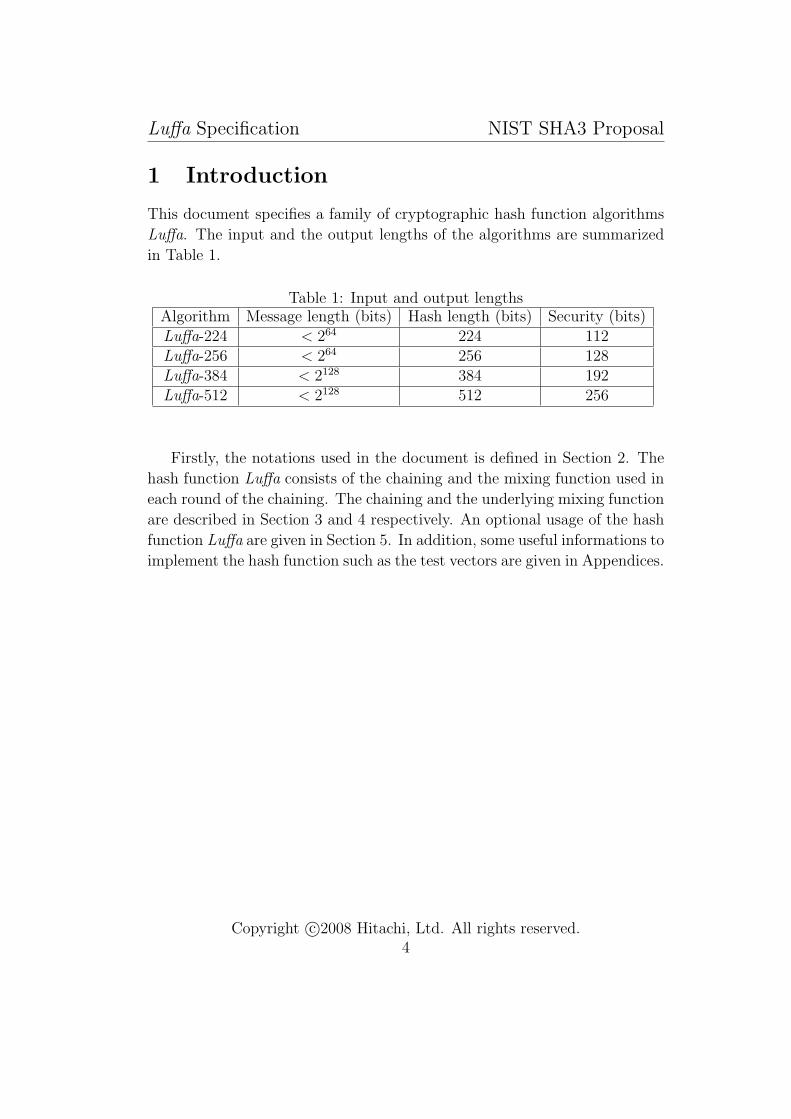
This document specifies a family of cryptographic hash function algorithms
Luffa. The input and the output lengths of the algorithms are summarized
in Table 1.
Table 1: Input and output lengthsAlgorithm Message length (bits) Hash length (bits) Security (bits)Luffa-224 < 264 224 112Luffa-256 < 264 256 128Luffa-384 < 2128 384 192Luffa-512 < 2128 512 256
Firstly, the notations used in the document is defined in Section 2. The
hash function Luffa consists of the chaining and the mixing function used in
each round of the chaining. The chaining and the underlying mixing function
are described in Section 3 and 4 respectively. An optional usage of the hash
function Luffa are given in Section 5. In addition, some useful informations to
implement the hash function such as the test vectors are given in Appendices.
Copyright c©2008 Hitachi, Ltd. All rights reserved.4
Luffa Specification NIST SHA3 Proposal
2 Preliminary
In this section, the basic terms and notations to describe the specification of
Luffa are defined.
2.1 Notations
2.1.1 Parameters
L: The message length in bitsL′: The padded message length in bitsN : The number of message block (of 256 bits)w: The number of sub-permutations (described in 3.2)nh: The hash lengthnb: The block length (Fixed to 256 bits in this document)Vj: The starting variables
H(i)j : The variable which specifies the intermediate values of the state at
i-th round, j-th blockM (i): The message block at the i-th round
i: A subscript which specifies the roundj: A subscript which specifies the sub-permutationk: A subscript which specifies the wordl: A subscript which specifies the bit position in a wordr: A subscript which specifies the step
MI: The message injection functionP : The permutation of nbw bitsQj The permutation dealing with j-th block of nb bits
OF : The output functionbj,k,l: The variable which specifies the k-th word, l-th bit of the input of
the j-th block permutation Qj
a(i,r)j,k,l : The variable which specifies the k-th word, l-th bit of the input of
i-th round, j-th block, r-th step function
x(i,r)j,k,l : The variable which specifies the k-th word, l-th bit of the output of
SubCrumb at i-th round, j-th block, r-th step
y(i,r)j,k,l : The variable which specifies the k-th word, l-th bit of the output of
MixWord at i-th round, j-th block, r-th step
Copyright c©2008 Hitachi, Ltd. All rights reserved.5

Luffa Specification NIST SHA3 Proposal
c(r)j,k,l: The variable which specifies the k-th word, l-th bit of the constant
used in j-th block, r-th step function
2.1.2 Symbols
In this paper, the following symbols are used to identify the operations.
⊕ Bitwise XOR operation∧ Bitwise AND operation|| Concatenation of two bit strings
≫ n Rotation n bits to the right (A 32-bit register is expected)≪ n Rotation n bits to the left (A 32-bit register is expected)0x Hexadecimal prefix
On the other hand, some pseudo codes are given in the paper. They are
written in C language manner and 32-bit registers are expected. In order to
remove any ambiguity, we also list up the operation used in the pseudo codes
as follows:
^ XOR operation| OR operation
>> n Shift n bits to the right<< n Shift n bits to the left
2.2 Data Structure
The basic data size is a 32-bit and it is called a word. A 4 bytes data is stored
to a word in the big endian manner. In other words, the given 4 bytes data
x0, . . . , x3 is stored into a word a as follows:
a = [MSB] x0||x1||x2||x3 [LSB],
where [MSB] (and [LSB]) means the most (and least) significant byte of the
word.
In the specification of Luffa, a 256-bit data block is stored in 8 32-bit
registers. In order to remove any ambiguity, we also define the ordering of a
Copyright c©2008 Hitachi, Ltd. All rights reserved.6
Luffa Specification NIST SHA3 Proposal
32 bytes data in 8 words. A 32 bytes data X = x0, x1, . . . , x31 is stored to 8
32-bit registers a0, . . . , a7 in the following manner:
X = [MSW] a0||a1|| · · · ||a7 [LSW],
ak = [MSB] x4k||x4k+1||x4k+2||x4k+3 [LSB], 0 ≤ k < 8,
where [MSW] (and [LSW]) means the most (and least) significant word.
A bit position in a word sequence is denoted by subscripts. Let a0, . . . , an
be a word sequence. Then the l-th bit (from the least significant bit) of the
k-th word is denoted by ak,l, where the least significant bit is the 0-th bit.
In other words, the bit information of ak is given by
ak = [msb] ak,31||ak,30|| · · · ||ak,1||ak,0 [lsb],
where [msb] and [lsb] mean the most and the least significant bit of the word
respectively.
2.3 Iterations
The message processing of Luffa is a chaining of a mixing function of a fixed
length input and a fixed length output. We call the mixing function as a
round function. The outline of the mixing function is defined in Section 3.
A term round means the procedure to apply the round function.
The building block of the round function is a family of non-linear permu-
tations defined in Section 4. It consists of iterations of a sub-function called
a step function. A term step means the procedure to apply the step function.
In order to clarify the round, the super-script with a parenthesis is used.
I.e., the input to the i-th round function is denoted by X(i−1). The corre-
sponding output of the round function is denoted by X(i) = Round(X(i−1)).
In the same manner, the input to the r-th step function of the i-th round
is denoted by X(i−1,r−1). The corresponding output of the step function is
denoted by X(i−1,r) = Step(X(i−1,r−1)). The round can be abbreviated if it
is not necessary in the context.
The intermediate state of Luffa consists of 8w words, where w ≥ 3 is a
positive integer (See Table 2 for the choice of w). An 8 words data is called
a block. The l-th bit of the input of i-th round, r-th step, j-th block, k-th
word is denoted by a(i−1,r−1)j,k,l .
Copyright c©2008 Hitachi, Ltd. All rights reserved.7
Luffa Specification NIST SHA3 Proposal
P H
C’
C’’P PMI MI MI
V0
V1
Vw - 1
M ( 1 ) M ( 2 ) M ( N )
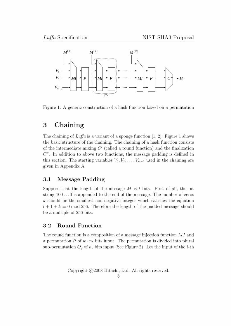
Figure 1: A generic construction of a hash function based on a permutation
3 Chaining
The chaining of Luffa is a variant of a sponge function [1, 2]. Figure 1 shows
the basic structure of the chaining. The chaining of a hash function consists
of the intermediate mixing C ′ (called a round function) and the finalization
C ′′. In addition to above two functions, the message padding is defined in
this section. The starting variables V0, V1, . . . , Vw−1 used in the chaining are
given in Appendix A
3.1 Message Padding
Suppose that the length of the message M is l bits. First of all, the bit
string 100 . . . 0 is appended to the end of the message. The number of zeros
k should be the smallest non-negative integer which satisfies the equation
l + 1 + k ≡ 0 mod 256. Therefore the length of the padded message should
be a multiple of 256 bits.
3.2 Round Function
The round function is a composition of a message injection function MI and
a permutation P of w · nb bits input. The permutation is divided into plural
sub-permutation Qj of nb bits input (See Figure 2). Let the input of the i-th
Copyright c©2008 Hitachi, Ltd. All rights reserved.8
Luffa Specification NIST SHA3 Proposal
round be (H(i−1)0 , . . . , H
(i−1)w−1 ), then the output of the i-th round is given by
H(i)j = Qj(Xj), 0 ≤ j < w,
X0|| · · · ||Xw−1 = MI(H(i−1)0 , . . . , H
(i−1)w−1 ,M (i)),
where H(0)j = Vj.
In the specification of Luffa, the input length of the sub-permutation Qj
is fixed to nb = 256 bits, and the number of the sub-permutations w is defined
in Table 2.
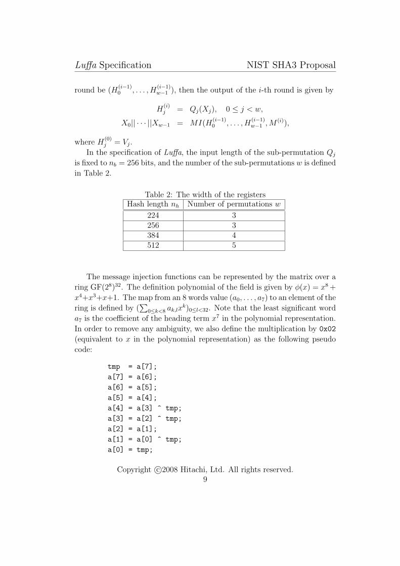
Table 2: The width of the registersHash length nh Number of permutations w
224 3256 3384 4512 5
The message injection functions can be represented by the matrix over a
ring GF(28)32. The definition polynomial of the field is given by φ(x) = x8 +
x4+x3+x+1. The map from an 8 words value (a0, . . . , a7) to an element of the
ring is defined by (∑
0≤k<8 ak,lxk)0≤l<32. Note that the least significant word
a7 is the coefficient of the heading term x7 in the polynomial representation.
In order to remove any ambiguity, we also define the multiplication by 0x02
(equivalent to x in the polynomial representation) as the following pseudo
code:
tmp = a[7];
a[7] = a[6];
a[6] = a[5];
a[5] = a[4];
a[4] = a[3] ^ tmp;
a[3] = a[2] ^ tmp;
a[2] = a[1];
a[1] = a[0] ^ tmp;
a[0] = tmp;
Copyright c©2008 Hitachi, Ltd. All rights reserved.9

Luffa Specification NIST SHA3 Proposal
In the following, the matrices representing the massage injection functions
MI for w = 3, 4, 5 are defined. How to implementing MI only with XORings
and multiplications by 0x02 is shown in Appendix E.
PMIM ( i )
H ( i )0
H ( i )1
H ( i - 1 )w - 1
H ( i - 1 )1
H ( i - 1 )0
H ( i )w - 1
Q1
Qw - 1
Q0
256 bits
2
2
2
Figure 2: The round function (w = 3)
3.2.1 Message Injection Function for w = 3
The matrix representation of the massage injection function MI for w = 3
is defined by
X0
X1
X2
=
3 2 2 1
2 3 2 2
2 2 3 4
H(i−1)0
H(i−1)1
H(i−1)2
M (i)
,
where numerics 0x01, 0x02, 0x03, 0x04 correspond to polynomials 1, x, x+1,
x2 respectively. The prefix 0x is omitted in order to reduce the redundancy.
Copyright c©2008 Hitachi, Ltd. All rights reserved.10
Luffa Specification NIST SHA3 Proposal
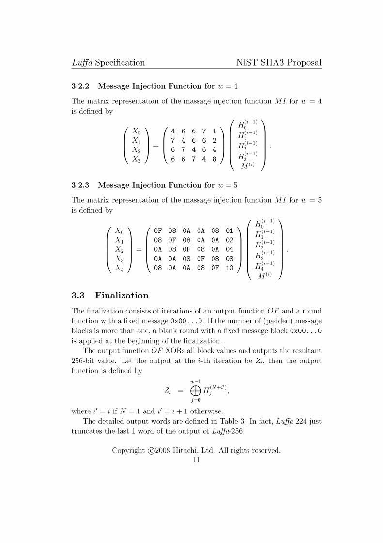
3.2.2 Message Injection Function for w = 4
The matrix representation of the massage injection function MI for w = 4
is defined by
X0
X1
X2
X3
=
4 6 6 7 1
7 4 6 6 2
6 7 4 6 4
6 6 7 4 8
H(i−1)0
H(i−1)1
H(i−1)2
H(i−1)3
M (i)
.
3.2.3 Message Injection Function for w = 5
The matrix representation of the massage injection function MI for w = 5
is defined by
X0
X1
X2
X3
X4
=
0F 08 0A 0A 08 01
08 0F 08 0A 0A 02
0A 08 0F 08 0A 04
0A 0A 08 0F 08 08
08 0A 0A 08 0F 10
H(i−1)0
H(i−1)1
H(i−1)2
H(i−1)3
H(i−1)4
M (i)
.
3.3 Finalization
The finalization consists of iterations of an output function OF and a round
function with a fixed message 0x00...0. If the number of (padded) message
blocks is more than one, a blank round with a fixed message block 0x00...0
is applied at the beginning of the finalization.
The output function OF XORs all block values and outputs the resultant
256-bit value. Let the output at the i-th iteration be Zi, then the output
function is defined by
Zi =w−1⊕j=0
H(N+i′)j ,
where i′ = i if N = 1 and i′ = i + 1 otherwise.
The detailed output words are defined in Table 3. In fact, Luffa-224 just
truncates the last 1 word of the output of Luffa-256.
Copyright c©2008 Hitachi, Ltd. All rights reserved.11

Luffa Specification NIST SHA3 Proposal
Q1
Qw - 1
Q0
Q1
Qw - 1
Q0
OF
Z0 Z1
H ( N )w - 1
H ( N )1
H ( N )0
256 bits
MI MI
0
a blank round(if N>1)
0
Figure 3: The finalization function
Table 3: The hash valuesHash length nh Hash value H
224 Z0,0|| · · · ||Z0,6
256 Z0,0|| · · · ||Z0,7
384 Z0,0|| · · · ||Z0,7||Z1,0|| · · · ||Z1,3
512 Z0,0|| · · · ||Z0,7||Z1,0|| · · · ||Z1,7
4 Non-Linear Permutation
In this section, the detailed specification of the permutation Qj. Some sub-
scripts such as i, j, r will be omitted in this section if it is clear in the context.
For example, a(i,r)j,k,l is denoted by ak,l.
4.1 Outline
The Luffa hash function uses a non-linear permutation Qj whose input and
output length is 256 bits. The permutation Qj is defined as a composition
of an input tweak and iterations of a step function Step. The number of
iterations of a step function is 8 and the tweak is applied only once per a
Copyright c©2008 Hitachi, Ltd. All rights reserved.12
Luffa Specification NIST SHA3 Proposal
SubCrumb (bit slice) SubCrumb (bit slice)
MixWord MixWord MixWord MixWord
AddConstant
a ( r - 1 )0 a ( r - 1 )
1 a ( r - 1 )2 a ( r - 1 )
3 a ( r - 1 )4 a ( r - 1 )
5 a ( r - 1 )6 a ( r - 1 )
7
a ( r )0 a ( r )
1 a ( r )2 a ( r )
3 a ( r )4 a ( r )
5 a ( r )6 a ( r )
7
32 bits
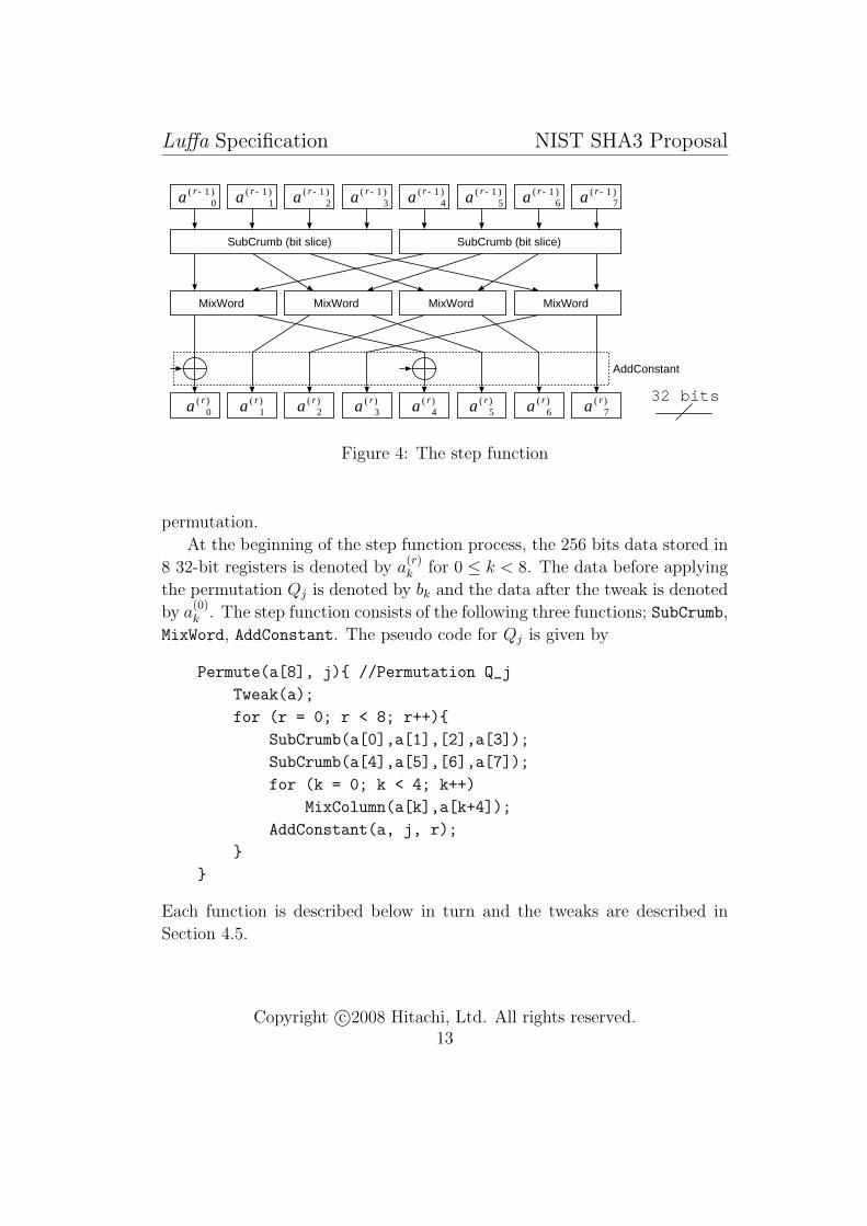
Figure 4: The step function
permutation.
At the beginning of the step function process, the 256 bits data stored in
8 32-bit registers is denoted by a(r)k for 0 ≤ k < 8. The data before applying
the permutation Qj is denoted by bk and the data after the tweak is denoted
by a(0)k . The step function consists of the following three functions; SubCrumb,
MixWord, AddConstant. The pseudo code for Qj is given by
Permute(a[8], j){ //Permutation Q_j
Tweak(a);
for (r = 0; r < 8; r++){
SubCrumb(a[0],a[1],[2],a[3]);
SubCrumb(a[4],a[5],[6],a[7]);
for (k = 0; k < 4; k++)
MixColumn(a[k],a[k+4]);
AddConstant(a, j, r);
}
}
Each function is described below in turn and the tweaks are described in
Section 4.5.
Copyright c©2008 Hitachi, Ltd. All rights reserved.13

Luffa Specification NIST SHA3 Proposal
4.2 SubCrumb
SubCrumb substitutes l-th bits of a0, a1, a2, a3 (or a4, a5, a6, a7) by an Sbox S
defined by
S[16] = {7, 13, 11, 10, 12, 4, 8, 3, 5, 15, 6, 0, 9, 1, 2, 14}.
Let the output of SubCrumb be x0, x1, x2, x3 (or x4, x5, x6, x7). Then the
substitution by SubCrumb is given by
x3,l||x2,l||x1,l||x0,l = S[a3,l||a2,l||a1,l||a0,l], 0 ≤ l < 32,
x7,l||x6,l||x5,l||x4,l = S[a7,l||a6,l||a5,l||a4,l], 0 ≤ l < 32.
S
a3 , l a2 , l a1 , l a0 , l
x0 , lx1 , lx2 , lx3 , l
1 bit
Figure 5: The input and output bits of the Sbox
Appendix D shows the optimal instruction set for Intel R© CoreTM2 Duo
processors 1.
4.3 MixWord
MixWord is a linear permutation of two words. Figure 6 shows the outline
of MixWord. Let the output words be yk and yk+4 where 0 ≤ k < 4. Then
MixWord given by the following equations:
yk+4 = xk+4 ⊕ xk,
yk = xk ≪ σ1,
yk = yk ⊕ yk+4,
1Intel R© is a registered trademark and CoreTM is a trademark of Intel Corporation inthe U.S. and other countries.
Copyright c©2008 Hitachi, Ltd. All rights reserved.14

Luffa Specification NIST SHA3 Proposal
<<<σ1
<<<σ2
<<<σ3
<<<σ4
xk xk +4
yk +4yk
32 bits
Figure 6: MixWord
yk+4 = yk+4 ≪ σ2,
yk+4 = yk+4 ⊕ yk,
yk = yk ≪ σ3,
yk = yk ⊕ yk+4,
yk+4 = yk+4 ≪ σ4.
The parameters σi are given by σ1 = 2, σ2 = 14, σ3 = 10, σ4 = 1.
4.4 AddConstant
AddConstant is given by
a(r)j,k = y
(r−1)j,k ⊕ c
(r−1)j,k , k = 0, 4.
Note that the step constant c(r−1)j,k is not equal to c
(r−1)j′,k if j 6= j′. The step
constants are generated sequentially from fixed initial values c(0)j,L and c
(0)j,R.
The initial values are given in Appendix B. The constant generation function
Copyright c©2008 Hitachi, Ltd. All rights reserved.15
Luffa Specification NIST SHA3 Proposal
fL
c( r - 1 )L
c( r )L c( r )
R
c( r - 1 )R
c( r - 1 )0
c( r - 1 )4
fL
32 bits
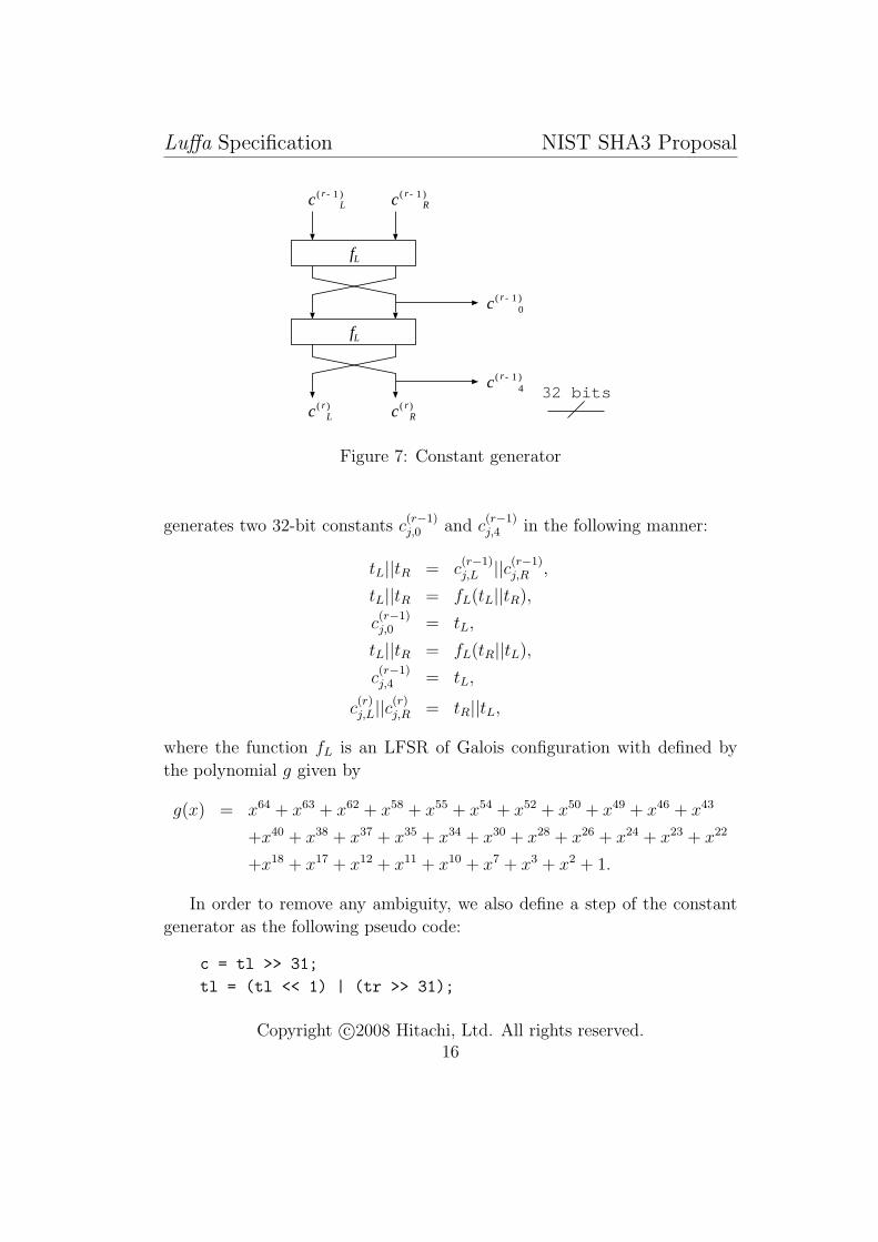
Figure 7: Constant generator
generates two 32-bit constants c(r−1)j,0 and c
(r−1)j,4 in the following manner:
tL||tR = c(r−1)j,L ||c(r−1)
j,R ,
tL||tR = fL(tL||tR),
c(r−1)j,0 = tL,
tL||tR = fL(tR||tL),
c(r−1)j,4 = tL,
c(r)j,L||c(r)
j,R = tR||tL,
where the function fL is an LFSR of Galois configuration with defined by
the polynomial g given by
g(x) = x64 + x63 + x62 + x58 + x55 + x54 + x52 + x50 + x49 + x46 + x43
+x40 + x38 + x37 + x35 + x34 + x30 + x28 + x26 + x24 + x23 + x22
+x18 + x17 + x12 + x11 + x10 + x7 + x3 + x2 + 1.
In order to remove any ambiguity, we also define a step of the constant
generator as the following pseudo code:
c = tl >> 31;
tl = (tl << 1) | (tr >> 31);
Copyright c©2008 Hitachi, Ltd. All rights reserved.16
Luffa Specification NIST SHA3 Proposal
tr = tr << 1;
if (c == 1){ tl ^= 0xc4d6496c; tr ^= 0x55c61c8d; }
SWAP(tl, tr);
step_const[j][r][k] = tr; /* k=0,4 */
4.5 Tweaks
For each permutation Qj, the least significant four words of a 256-bit input
are rotated j bits to the left in 32-bit registers. Let the j-th block, k-th
word input be bj,k and the tweaked word (namely the input to the first step
function) be a(0)j,k , then the tweak is defined by
a(0)j,k,l = bj,k,l, 0 ≤ k < 4,
a(0)j,k,l = bj,k,(l−j mod 32), 4 ≤ k < 8.
5 Optional Usage
Dispite the size of the outputs being specified in Section 3.3, the design of
Luffa allows to generate bit strings of arbitrary length by iterating the output
function OF and the round function Round. This feature is useful for some
applications. On the other hand, it should be pointed out that a longer
output with a small w does not improve the security level.
References
[1] G. Bertoni, J. Daemen, M. Peeters and G. Van Assche, “Sponge Func-
tions,” Ecrypt Hash Workshop 2007.
[2] G. Bertoni, J. Daemen, M. Peeters and G. Van Assche, “On the In-
differentiability of the Sponge Construction,” Advances in Cryptology,
Eurocrypt 2008, pp. 181–197, 2008.
[3] National Institute of Standards and Technology, “Secure Hash Stan-
dard,” FIPS 180-2.
Copyright c©2008 Hitachi, Ltd. All rights reserved.17
Luffa Specification NIST SHA3 Proposal
[4] National Institute of Standards and Technology, “Digital Sigunature
Standard,” FIPS 186-2.
[5] National Institute of Standards and Technology, “The Keyed-Hash Mes-
sage Authentication Code (HMAC),” FIPS 198.
[6] National Institute of Standards and Technology, “Recommendation for
Pair-Wise Key Establishment Schemes Using Discrete Logarithm Cryp-
tography,” SP 800-56A.
[7] National Institute of Standards and Technology, “Recommendation for
Number Generation Using Deterministic Random Bit Generators (DR-
BGs),” SP 800-90.
[8] National Institute of Standards and Technology, “The Advanced En-
cryption Standard Algorithm Validation Suite (AESAVS)”.
Copyright c©2008 Hitachi, Ltd. All rights reserved.18
Luffa Specification NIST SHA3 Proposal
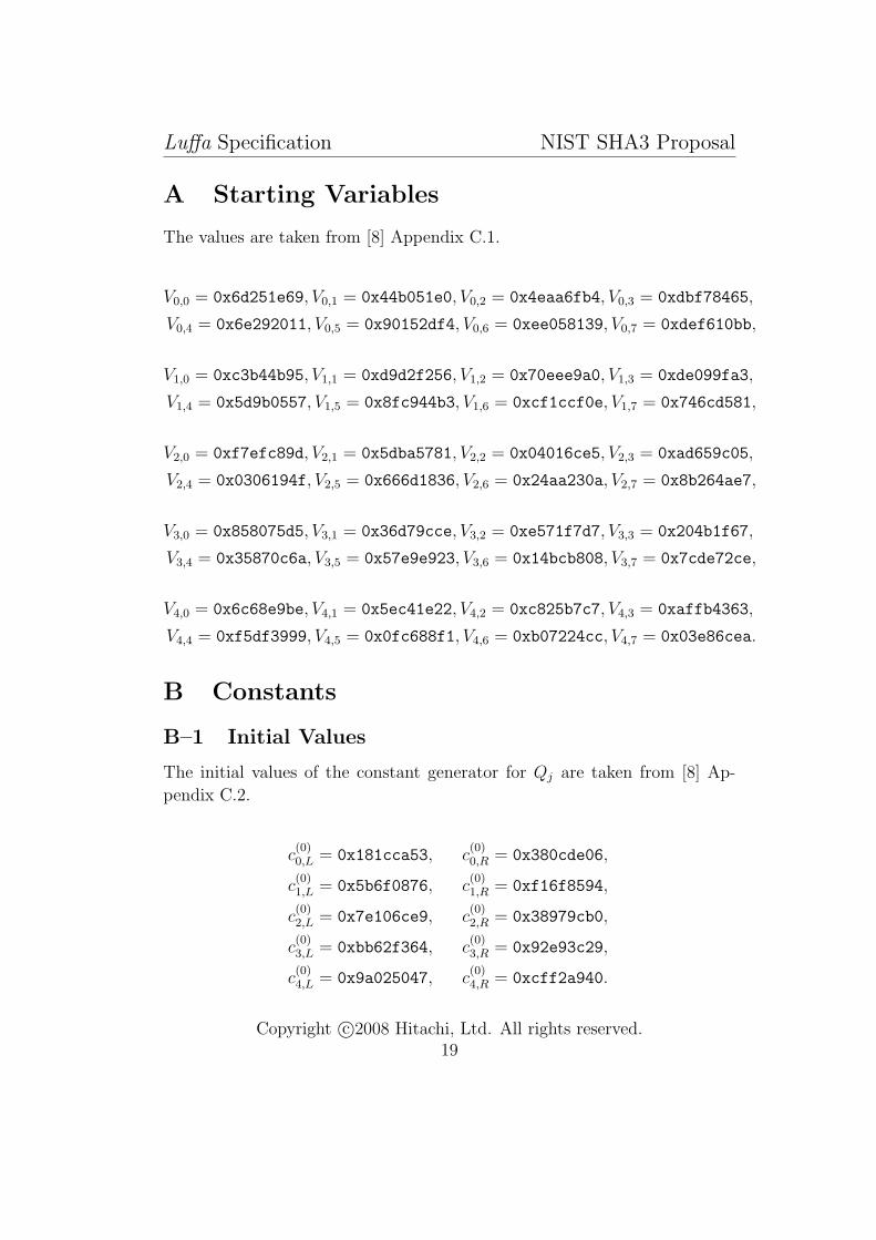
A Starting Variables
The values are taken from [8] Appendix C.1.
V0,0 = 0x6d251e69, V0,1 = 0x44b051e0, V0,2 = 0x4eaa6fb4, V0,3 = 0xdbf78465,
V0,4 = 0x6e292011, V0,5 = 0x90152df4, V0,6 = 0xee058139, V0,7 = 0xdef610bb,
V1,0 = 0xc3b44b95, V1,1 = 0xd9d2f256, V1,2 = 0x70eee9a0, V1,3 = 0xde099fa3,
V1,4 = 0x5d9b0557, V1,5 = 0x8fc944b3, V1,6 = 0xcf1ccf0e, V1,7 = 0x746cd581,
V2,0 = 0xf7efc89d, V2,1 = 0x5dba5781, V2,2 = 0x04016ce5, V2,3 = 0xad659c05,
V2,4 = 0x0306194f, V2,5 = 0x666d1836, V2,6 = 0x24aa230a, V2,7 = 0x8b264ae7,
V3,0 = 0x858075d5, V3,1 = 0x36d79cce, V3,2 = 0xe571f7d7, V3,3 = 0x204b1f67,
V3,4 = 0x35870c6a, V3,5 = 0x57e9e923, V3,6 = 0x14bcb808, V3,7 = 0x7cde72ce,
V4,0 = 0x6c68e9be, V4,1 = 0x5ec41e22, V4,2 = 0xc825b7c7, V4,3 = 0xaffb4363,
V4,4 = 0xf5df3999, V4,5 = 0x0fc688f1, V4,6 = 0xb07224cc, V4,7 = 0x03e86cea.
B Constants
B–1 Initial Values
The initial values of the constant generator for Qj are taken from [8] Ap-
pendix C.2.
c(0)0,L = 0x181cca53, c
(0)0,R = 0x380cde06,
c(0)1,L = 0x5b6f0876, c
(0)1,R = 0xf16f8594,
c(0)2,L = 0x7e106ce9, c
(0)2,R = 0x38979cb0,
c(0)3,L = 0xbb62f364, c
(0)3,R = 0x92e93c29,
c(0)4,L = 0x9a025047, c
(0)4,R = 0xcff2a940.
Copyright c©2008 Hitachi, Ltd. All rights reserved.19
Luffa Specification NIST SHA3 Proposal
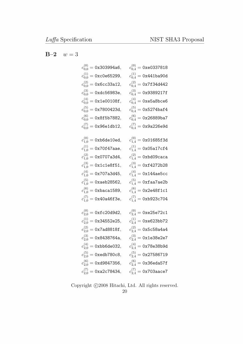
B–2 w = 3
c(0)0,0 = 0x303994a6, c
(0)0,4 = 0xe0337818
c(1)0,0 = 0xc0e65299, c
(1)0,4 = 0x441ba90d
c(2)0,0 = 0x6cc33a12, c
(2)0,4 = 0x7f34d442
c(3)0,0 = 0xdc56983e, c
(3)0,4 = 0x9389217f
c(4)0,0 = 0x1e00108f, c
(4)0,4 = 0xe5a8bce6
c(5)0,0 = 0x7800423d, c
(5)0,4 = 0x5274baf4
c(6)0,0 = 0x8f5b7882, c
(6)0,4 = 0x26889ba7
c(7)0,0 = 0x96e1db12, c
(7)0,4 = 0x9a226e9d
c(0)1,0 = 0xb6de10ed, c
(0)1,4 = 0x01685f3d
c(1)1,0 = 0x70f47aae, c
(1)1,4 = 0x05a17cf4
c(2)1,0 = 0x0707a3d4, c
(2)1,4 = 0xbd09caca
c(3)1,0 = 0x1c1e8f51, c
(3)1,4 = 0xf4272b28
c(4)1,0 = 0x707a3d45, c
(4)1,4 = 0x144ae5cc
c(5)1,0 = 0xaeb28562, c
(5)1,4 = 0xfaa7ae2b
c(6)1,0 = 0xbaca1589, c
(6)1,4 = 0x2e48f1c1
c(7)1,0 = 0x40a46f3e, c
(7)1,4 = 0xb923c704
c(0)2,0 = 0xfc20d9d2, c
(0)2,4 = 0xe25e72c1
c(1)2,0 = 0x34552e25, c
(1)2,4 = 0xe623bb72
c(2)2,0 = 0x7ad8818f, c
(2)2,4 = 0x5c58a4a4
c(3)2,0 = 0x8438764a, c
(3)2,4 = 0x1e38e2e7
c(4)2,0 = 0xbb6de032, c
(4)2,4 = 0x78e38b9d
c(5)2,0 = 0xedb780c8, c
(5)2,4 = 0x27586719
c(6)2,0 = 0xd9847356, c
(6)2,4 = 0x36eda57f
c(7)2,0 = 0xa2c78434, c
(7)2,4 = 0x703aace7
Copyright c©2008 Hitachi, Ltd. All rights reserved.20

Luffa Specification NIST SHA3 Proposal
B–3 w = 4
c(0)3,0 = 0xb213afa5, c
(0)3,4 = 0xe028c9bf
c(1)3,0 = 0xc84ebe95, c
(1)3,4 = 0x44756f91
c(2)3,0 = 0x4e608a22, c
(2)3,4 = 0x7e8fce32
c(3)3,0 = 0x56d858fe, c
(3)3,4 = 0x956548be
c(4)3,0 = 0x343b138f, c
(4)3,4 = 0xfe191be2
c(5)3,0 = 0xd0ec4e3d, c
(5)3,4 = 0x3cb226e5
c(6)3,0 = 0x2ceb4882, c
(6)3,4 = 0x5944a28e
c(7)3,0 = 0xb3ad2208, c
(7)3,4 = 0xa1c4c355
B–4 w = 5
c(0)4,0 = 0xf0d2e9e3, c
(0)4,4 = 0x5090d577
c(1)4,0 = 0xac11d7fa, c
(1)4,4 = 0x2d1925ab
c(2)4,0 = 0x1bcb66f2, c
(2)4,4 = 0xb46496ac
c(3)4,0 = 0x6f2d9bc9, c
(3)4,4 = 0xd1925ab0
c(4)4,0 = 0x78602649, c
(4)4,4 = 0x29131ab6
c(5)4,0 = 0x8edae952, c
(5)4,4 = 0x0fc053c3
c(6)4,0 = 0x3b6ba548, c
(6)4,4 = 0x3f014f0c
c(7)4,0 = 0xedae9520, c
(7)4,4 = 0xfc053c31
Copyright c©2008 Hitachi, Ltd. All rights reserved.21
Luffa Specification NIST SHA3 Proposal
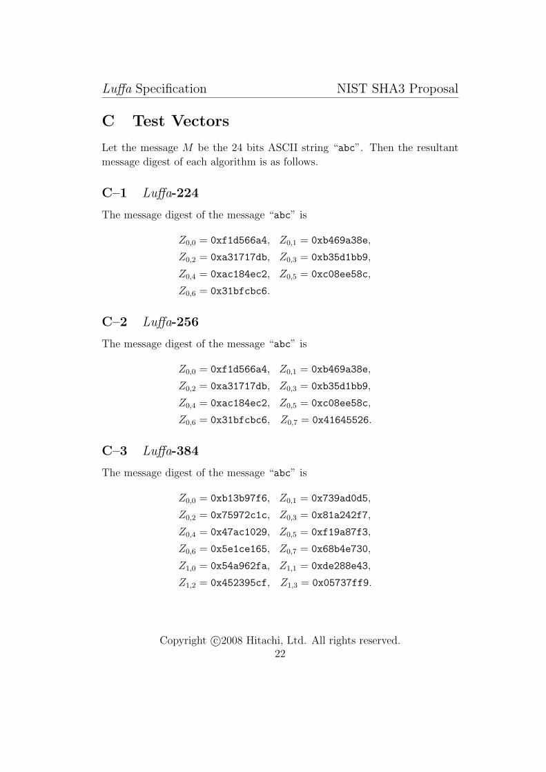
C Test Vectors
Let the message M be the 24 bits ASCII string “abc”. Then the resultant
message digest of each algorithm is as follows.
C–1 Luffa-224
The message digest of the message “abc” is
Z0,0 = 0xf1d566a4, Z0,1 = 0xb469a38e,
Z0,2 = 0xa31717db, Z0,3 = 0xb35d1bb9,
Z0,4 = 0xac184ec2, Z0,5 = 0xc08ee58c,
Z0,6 = 0x31bfcbc6.
C–2 Luffa-256
The message digest of the message “abc” is
Z0,0 = 0xf1d566a4, Z0,1 = 0xb469a38e,
Z0,2 = 0xa31717db, Z0,3 = 0xb35d1bb9,
Z0,4 = 0xac184ec2, Z0,5 = 0xc08ee58c,
Z0,6 = 0x31bfcbc6, Z0,7 = 0x41645526.
C–3 Luffa-384
The message digest of the message “abc” is
Z0,0 = 0xb13b97f6, Z0,1 = 0x739ad0d5,
Z0,2 = 0x75972c1c, Z0,3 = 0x81a242f7,
Z0,4 = 0x47ac1029, Z0,5 = 0xf19a87f3,
Z0,6 = 0x5e1ce165, Z0,7 = 0x68b4e730,
Z1,0 = 0x54a962fa, Z1,1 = 0xde288e43,
Z1,2 = 0x452395cf, Z1,3 = 0x05737ff9.
Copyright c©2008 Hitachi, Ltd. All rights reserved.22

Luffa Specification NIST SHA3 Proposal
C–4 Luffa-512
The message digest of the message “abc” is
Z0,0 = 0x4c1faae4, Z0,1 = 0xbda064ee,
Z0,2 = 0x9c50b695, Z0,3 = 0x2eb95c3e,
Z0,4 = 0x1026c684, Z0,5 = 0x0b9e498c,
Z0,6 = 0x2514eb93, Z0,7 = 0x78377fe9,
Z1,0 = 0xef2d6d1e, Z1,1 = 0x17bc3953,
Z1,2 = 0x46982d1c, Z1,3 = 0xbb8ce685,
Z1,4 = 0x5f4602c8, Z1,5 = 0xbf2ed11b,
Z1,6 = 0xfcd3e453, Z1,7 = 0x314b1feb.
D Implementations of SubCrumb
D–1 For Intel R© 686 Processors
The instructions are given by Table 4. At the first, the four words data
Table 4: The instructions set for Intel R© 686 processorscycle
1 MOV r4 r0 XOR r2 r1 AND r0 r1
2 XOR r0 r2 NOT r1 OR r2 r4
3 XOR r2 r3 XOR r4 r0 AND r3 r0
4 XOR r3 r1 NOT r4 OR r1 r2
5 XOR r4 r1 XOR r0 r3 AND r1 r2
6 XOR r1 r3
a0, a1, a2, a3 are loaded to the registers r0, r1, r2, r3 respectively. Then
the resultant registers r0, r1, r3, r4 provides the outputs of Sbox, namely,
x0 = r0, x1 = r1, x2 = r3, x3 = r4.
Copyright c©2008 Hitachi, Ltd. All rights reserved.23
Luffa Specification NIST SHA3 Proposal
E Implementations of Message Injection Func-
tion MI
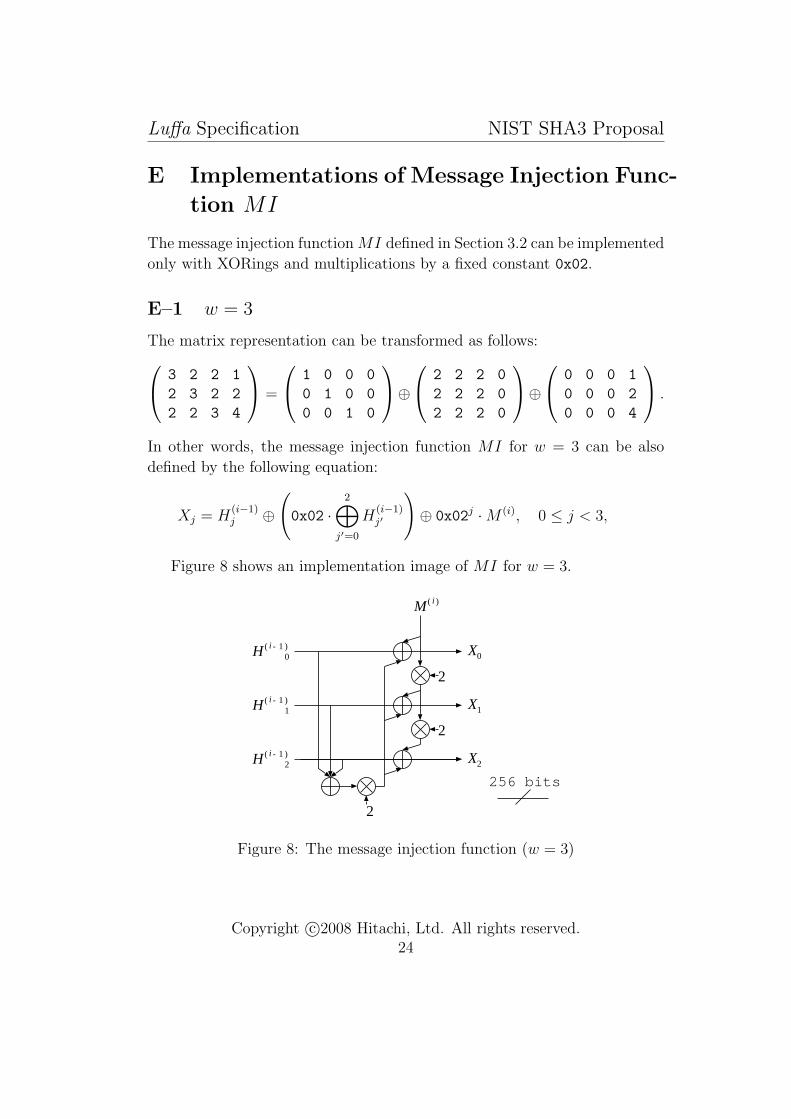
The message injection function MI defined in Section 3.2 can be implemented
only with XORings and multiplications by a fixed constant 0x02.
E–1 w = 3
The matrix representation can be transformed as follows:
3 2 2 1
2 3 2 2
2 2 3 4
=
1 0 0 0
0 1 0 0
0 0 1 0
⊕
2 2 2 0
2 2 2 0
2 2 2 0
⊕
0 0 0 1
0 0 0 2
0 0 0 4
.
In other words, the message injection function MI for w = 3 can be also
defined by the following equation:
Xj = H(i−1)j ⊕
(0x02 ·
2⊕
j′=0
H(i−1)j′
)⊕ 0x02j ·M (i), 0 ≤ j < 3,
Figure 8 shows an implementation image of MI for w = 3.
M ( i )
H ( i - 1 )1
2
2
X1
X2
256 bits
H ( i - 1 )2
H ( i - 1 )0
2
X0
Figure 8: The message injection function (w = 3)
Copyright c©2008 Hitachi, Ltd. All rights reserved.24
Luffa Specification NIST SHA3 Proposal
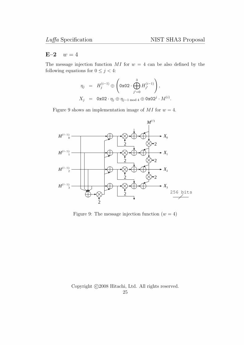
E–2 w = 4
The message injection function MI for w = 4 can be also defined by the
following equations for 0 ≤ j < 4:
ηj = H(i−1)j ⊕
(0x02 ·
3⊕
j′=0
H(i−1)j′
),
Xj = 0x02 · ηj ⊕ ηj−1 mod 4 ⊕ 0x02j ·M (i).
Figure 9 shows an implementation image of MI for w = 4.
M ( i )
H ( i - 1 )1
2
2
2
X1
X2
256 bits
H ( i - 1 )2
H ( i - 1 )0
2
X0
X3H ( i - 1 )3
2
2
2
2
Figure 9: The message injection function (w = 4)
Copyright c©2008 Hitachi, Ltd. All rights reserved.25

Luffa Specification NIST SHA3 Proposal
E–3 w = 5
The message injection function MI for w = 5 can be also defined by the
following equations for 0 ≤ j < 5:
ηj = H(i−1)j ⊕
(0x02 ·
4⊕
j′=0
H(i−1)j′
),
ξj = 0x02 · ηj ⊕ ηj+1 mod 5,
Xj = 0x02 · ξj ⊕ ξj−1 mod 5 ⊕ 0x02j ·M (i).
Figure 10 shows an implementation image of MI for w = 5.
M ( i )
H ( i - 1 )1
2
2
X1
X2H ( i - 1 )2
H ( i - 1 )0
2
X0
X3H ( i - 1 )3
2
2
2
2
2
256 bits2
H ( i - 1 )4 X4
22
2
2
2
2
Figure 10: The message injection function (w = 5)
Copyright c©2008 Hitachi, Ltd. All rights reserved.26


