
Ground loops

Earthing of electrical systems is required for a number of reasons, principally to ensure the safety of people near the system and to prevent damage to the system itself in the event of a fault. The function of the protective conductor, or earth, is to provide a low resistance path for fault current so that the circuit protective devices operate rapidly to disconnect the supply.

In an electrical system, a ground loop usually refers to a current, almost always unwanted, in a conductor connecting
two points that are supposed to be at the same potential, often ground, but are actually at different potentials. Ground
loops created by improperly designed or improperly installed equipment are a major cause
of noise and interference in audio and video systems. They can also create an electric shock hazard, since ostensibly
"grounded" parts of the equipment, which are often accessible to users, are not at ground potential.

Any type of unwanted or unexpected current flowing
through a ground line is referred to as a “ground loop”. Noise in the ground lines is also referred to as a ground loop problem. The basic concept of the ground loop is
shown in the following illustration.

If the two ends of a wire are earth-grounded at different locations, the voltage difference between the two “ground” points can drivesignificant currents (often several amps) through the wire. Consider the wire to be part of a loop which contains a voltage source that represents the difference in potential between the two ground points, and you have the classical “ground loop”.

All types of equipment are susceptible to ground loops:• multimedia• Medical• Industrial• data processing.
Ground loops can cause data errors, component failure , lock-ups, and even safety
hazards.
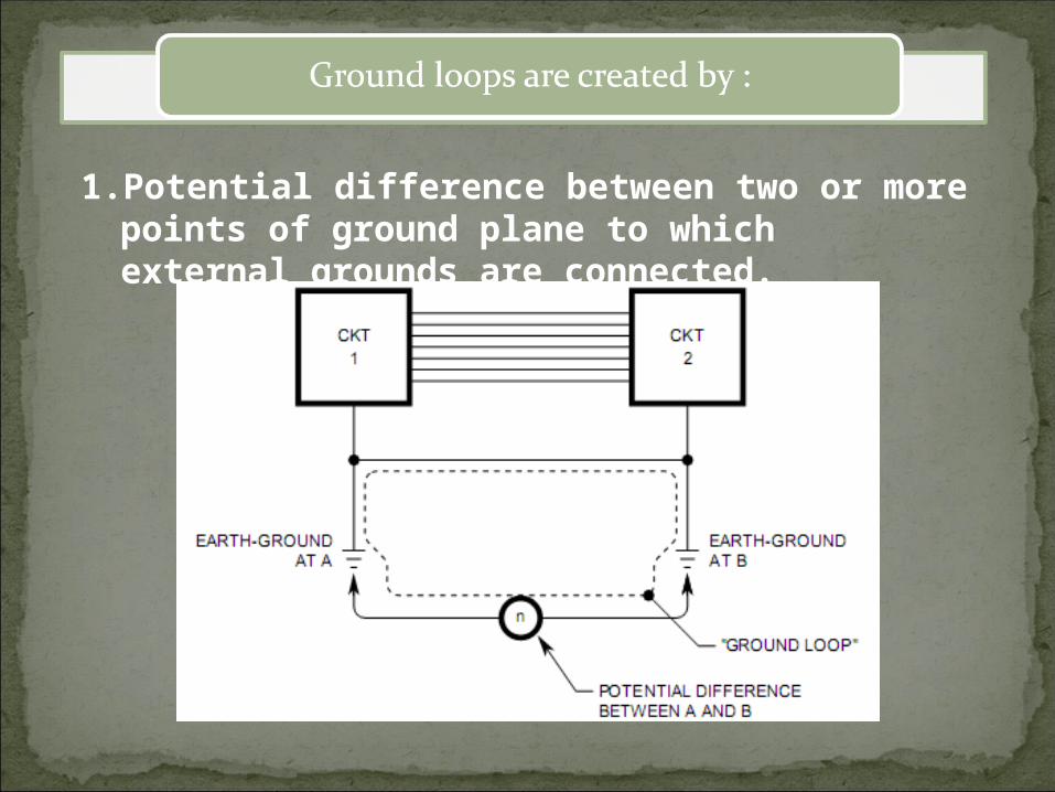
1. Potential difference between two or more points of ground plane to which external grounds are connected.

2. Inductive coupling :

2. Inductive coupling :

3. Capacitive coupling :3. Capacitive coupling :

4. Common - mode - noise :4. Common - mode - noise : Common mode noise is electrical interference on the two signal lines that causes both lines to change in potential relative to ground. Common mode noise most often results when the ground potential between the measuring instrument and the device being measured are different. The difference in grounds results in a ground loop, a current flowing through ground and the low lead. Once this current appears in the low lead wire it will cause a voltage because the wire has some resistance. The longer the lead, the more lead resistance and the greater the voltage error. TIP: TIP: To reduce common mode noise, use a guarded voltmeter. Tie the guard to the low side of the device being measured. This will shunt any ground loop currents away from the high and low measurement wires.

4. Common - mode - noise :4. Common - mode - noise :

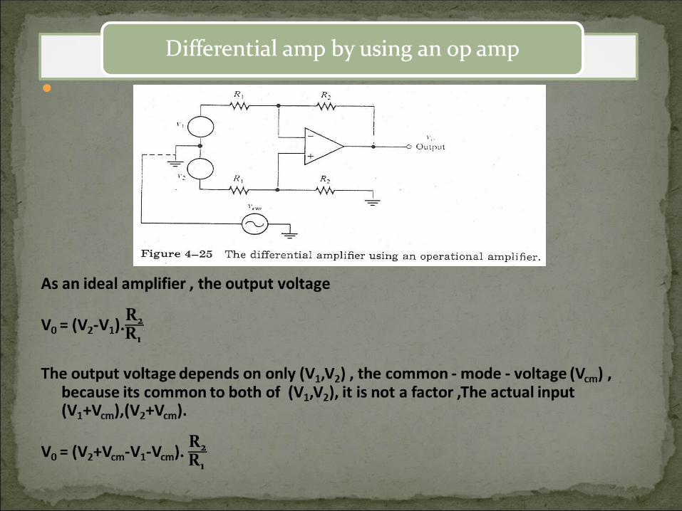
Single point grounding (not safe). Use of differential amplifier.


Name : mohammad abdullatif assa al damatyName : mohammad abdullatif assa al damatyID : 0090618ID : 0090618


