Download - Fundamentals of Solar PV System

Fundamentals of Solar PV system

Solar Energy Basics and solar spectrum
Photovoltaic Cell: Construction and working principleSolar photovoltaic technologiesTypes of solar photovoltaic systems
Designing of a solar photovoltaic system
Advantages and disadvantages of solar energy and systems
Applications of solar energy
Outline

What is Solar Energy?
Originates with the thermonuclear fusion reactions occurring in
the sun.
Represents the entire electromagnetic radiation (visible light,
infrared, ultraviolet, x-rays, and radio waves).
This energy consists of radiant light and heat energy from the sun.
Out of all energy emitted by sun only a small fraction of energy is
absorbed by the earth.

http://en.wikipedia.org/wiki/File:Breakdown_of_the_incoming_solar_energy.svg
The surface receives about 47% of the total solar energy that reaches the Earth. Only this amount is usable.
Breakdown of incoming solar energy


Air Mass
Amount of air mass through which light pass Atmosphere can cut solar energy reaching earth by 50%
and more

Solar Thermal Energy
Solar Heating
Solar Water Heating
Solar Space Heating
Solar Space Cooling
Solar Photovoltaic
Solar Concentrators
Solar Energy Harvesting Using Different Paths

Electricity Generation From Solar Energy
Solar Energy can be used to generate electricity in 2 ways:
Solar Thermal Energy:
Using solar thermal technologies for heating fluids which can be
used as a heat source or to run turbines to generate electricity.
Solar Photovoltaic Energy:
Using solar energy for the direct generation of electricity
using photovoltaic phenomenon.

Technology Options for Solar Power
Parabolic Dish
Solar Power
Thermal
Low Temperature
<100°C.
Solar Water Heating
Solar Chimney
Solar Pond
Med Temp <400°C
High Temp. >400°C
Central Tower
PV
Technology
Mono Crystalline
Silicon
Polycrystalline Silicon
Amorphous Silicon
Production Process
Wafer
Thin Film

Energy Band Diagram of a Conductor, Semiconductor and Insulator
conductor semiconductor insulator
Semiconductors are interested because their conductivity can be readily modulated (by impurity
doping or electrical potential), offering a pathway to control electronic circuits.

Semiconductors used for solar cells
II III IV V VI
B C (6)Al Si (14) P S
Zn Ga Ge (32) As Se
Cd In Sb Te
Semiconductors: Elementary – Si, Ge. Compound – GaAs, InP, CdTe. Ternary – AlGaAs, HgCdTe, CIS. Quaternary – CIGS, InGaAsP, InGaAIP.

Silicon
Si
Si
Si
Si
Si-
Si Si Si
Si
SiSi
Si
Si
Si
Shared electrons
Silicon is group IV element – with 4 electrons in their valence shell. When silicon atoms are brought together, each atom forms covalent bond with
4 silicon atoms in a tetrahedron geometry.

Intrinsic Semiconductor At 0 ºK, each electron is in its lowest energy state so each covalent bond
position is filled. If a small electric field is applied to the material, no electrons will move because they are bound to their individual atoms.
At 0 ºK, silicon is an insulator. As temperature increases, the valence electrons gain thermal energy. If a valence electron gains enough energy (Eg), it may break its covalent bond
and move away from its original position. This electron is free to move within the crystal.
Conductor Eg <0.1eV, many electrons can be thermally excited at room temperature.
Semiconductor Eg ~1eV, a few electrons can be excited (e.g. 1/billion) Insulator, Eg >3-5eV, essentially no electron can be thermally excited at room
temperature.
Energy of a photon,

Extrinsic Semiconductor, n-type Doping
Electron
-
Si Si Si
Si
SiSi
Si
Si
As
Extra
Valence band, Ev
Eg = 1.1 eV
Conducting band, Ec
Ed ~ 0.05 eV
Doping silicon lattice with group V elements can creates extra electrons in the conduction
band — negative charge carriers (n-type), As- donor.
Doping concentration #/cm3 (1016/cm3 ~ 1/million).

Valence band, Ev
Eg = 1.1 eV
Conducting band, Ec
Ea ~ 0.05 eV
Electron
-
Si Si Si
Si
SiSi
Si
Si
B
Hole
Doping silicon with group III elements can creates empty holes in the valence band
positive charge carriers (p-type), B-(acceptor).
Extrinsic Semiconductor, p-type doping

V
I
R O F
p n
p n
V>0 V<0
Reverse bias Forward bias
p-n Junction diode
A p-n junction is a junction formed by combining p-type and n-type semiconductors together in very close contact.
In p-n junction, the current is only allowed to flow along one direction from p-type to n-type materials.
i
p nV<0 V>0
depletion layer
- +

Get image from book
Efficiency – The Band Gap Problem

Photo+voltaic = convert light to electricity

A PV cell is a light illuminated pn-junction diode which directly converts solar energy into electricity via the photovoltaic effect.
A typical silicon PV cell is composed of a thin wafer consisting of an ultra-thin layer of phosphorus-doped (n-type) silicon on top of a thicker layer of boron-doped (p-type) silicon.
When sunlight strikes the surface of a PV cell, photons with energy above the semiconductor bandgap impart enough energy to create electron-hole pairs.
Photovoltaic Cell

Photovoltaic Cell: Operating Principle
There are three basic steps for
generation of electricity using PV cells
which are following:
First is absorption of solar
radiation,
Second is generation of free
charge carriers and
Third is transport and then
collection of charge carriers at PV
cell terminals.

Structure of a Solar Cell

1) Non absorbed photons
2) Lattice thermalization
3) Junction voltage drop
4) Contact voltage drop
5) Recombination
Standard PV cell Efficiency Losses

Blocking Diodes During sun shine, as long as the voltage produced by the panels is greater
than that of the battery, charging will take place.
In the dark, the voltage of the battery would cause a current flow in
reverse direction through the panels, which can lead to the discharging of
battery.
A blocking diode is used in series with the panels and battery in reverse
biasing to prevent reverse flow of the current.
Normal p-n junction diodes can be used as blocking diodes.
To select a blocking diode, following parameters should be kept in mind:
The maximum current provided by the panels.
The voltage ratings of the diode.
The reverse breakdown voltage of the diode.

Hot- Spot and Bypass Diodes
Hot Spot phenomenon happens when one or more
cells of the panel is shaded while the others are
illuminated.
The shaded cells/panels starts behaving as a diode
polarized in reverse direction and generates reverse
power. The other cells generate a current that flows
through the shaded cell and the load.

Any solar cell has its own critical power
dissipation Pc that must not be exceeded and
depends on its cooling and material structures, its
area, its maximum operating temperature and
ambient temperature.
A shaded cell may be destroyed when its reverse
dissipation exceeds Pc. This is the hot spot.
To eliminate the hot-spot phenomenon, a bypass
diode is connected parallel to the module or
group of cells in reverse polarity which provides
another path to the extra current.
Hot- Spot and Bypass Diodes

When part of a PV module is shaded, the shaded cells will not be able to produce as much current as the unshaded cells.
Since all cells are connected in series, the same amount of current must flow through every cell.
The unshaded cells will force the shaded cells to pass more current through it.
Bypass diode working phases
Bypass Diodes working

The only way the shaded cells can operate at a current higher than their short
circuit current is to operate in a region of negative voltage i.e. to cause a net
voltage loss to the system.
The voltage across the shaded or low current solar cell becomes greater than the
forward bias voltage of the other series cells which share the same bypass diode
plus the voltage of the bypass diode thus making the diode to work in forward
bias and hence allowing extra current to pass through it, preventing hot-spot.
For an efficient operation, there are two conditions to fulfill:
Bypass diode has to conduct when one cell is shadowed.
The shadowed cell voltage Vs must stay under its breakdown voltage (Vc).
Ideally, a bypass diode should have a forward voltage (VF) and a leakage current
(IR) as low as possible.
Bypass Diodes working

Bypass Diodes
Two types of diodes are available as bypass diodes in solar
panels and arrays:
p-n junction silicon diode
Schottky barrier diode
To select a bypass diode, following parameters should be
checked:
The forward voltage and current ratings of the diode.
The reverse breakdown voltage of the diode.
The reverse leakage current.
Junction Temperature Range

2 – 3 W
100 - 200 W
10 - 50 kW
Cell
Array
Module,Panel
Volt Ampere Watt Size
Cell 0.5V 5-6A 2-3W about 10cm
Module 20-30V 5-6A 100-200W about 1m
Array 200-300V 50A-200A 10-50kW about 30m
6x9=54 (cells) 100-300 (modules)
Hierarchy of PV

Solar cells are composed of various semiconducting materials
Crystalline silicon
Cadmium telluride
Copper indium diselenide
Gallium arsenide
Indium phosphide
Zinc sulphide
Materials for Solar cell

Cell Technologies
Crystalline
silicon
Mono-crystalli
ne
Pure and
efficient15-19% efficienc
yMulti-
crystalline
12-15% efficienc
y
Thin film
Non Silicon based
CdTe8.5%
efficiency
CIGS9-11%
efficiency
Silicon based
Amorphous
5-7% efficienc
y

Technology DifferencesOptical Properties
• Band gap (direct, indirect)
• Absorption Coefficient• Absorption length
Electrical Properties
• Carrier Lifetime• Mobility• Diffusion length
Manufacturing
• Absorber material• Cells• Modules
Performance
• Efficiency• Current, Voltage and FF• Effect of temperature
and radiation

Optical Properties: Band Gaps
Fixed band gap of c-Si material (mono, multi).Tunable gaps of thin film compound semiconductors.

Optical Properties: Material absorption lengths
Absorption Length in Microns(for approx. 73% incoming light absorption)
Wavelength (nm)
c-Si a-Si CIGS GaAs
400 nm (3.1eV) 0.15 0.05 0.05 0.09600 nm (2eV) 1.8 0.14 0.06 0.18
800 nm (1.55eV)
9.3 Not absorbed
0.14 1.1
1000nm(1.24eV)
180.9 Not absorbed
0.25 Not absorbed
Absorption length is much higher for Si because of lower absorption coefficient.
Longer wavelength photons require more materials to get absorbed.
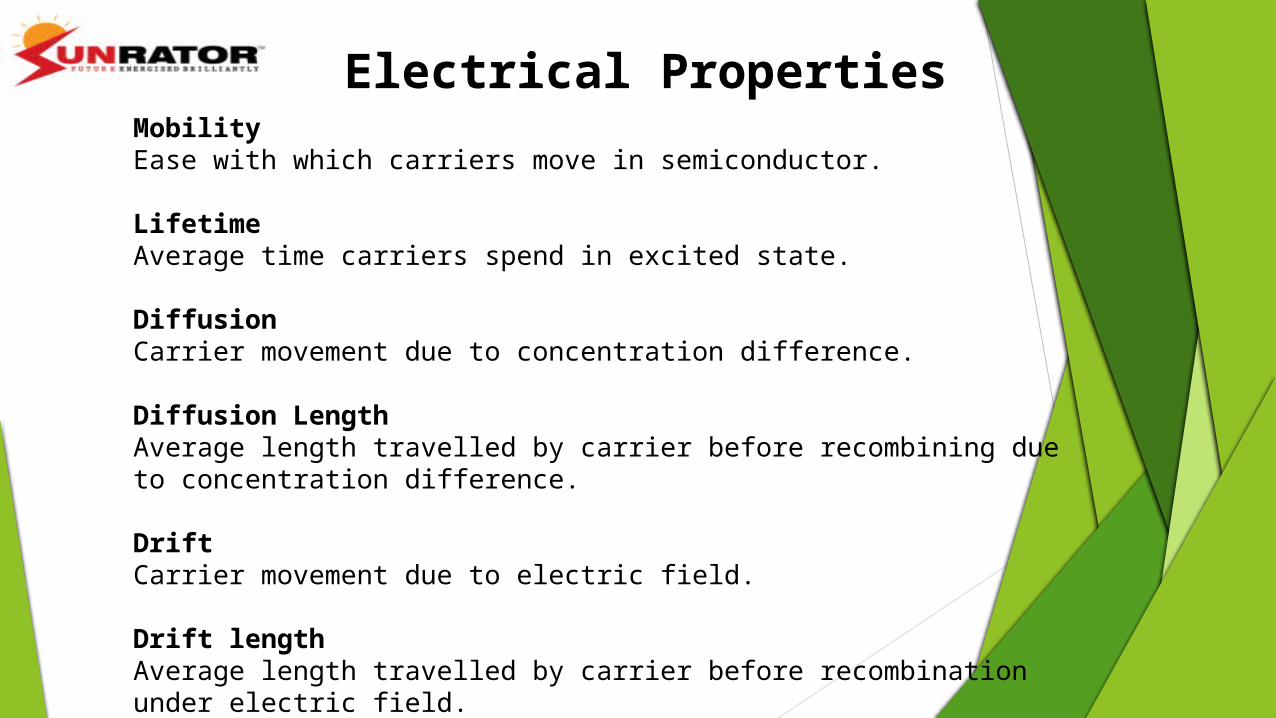
Electrical PropertiesMobilityEase with which carriers move in semiconductor.
LifetimeAverage time carriers spend in excited state.
DiffusionCarrier movement due to concentration difference.
Diffusion LengthAverage length travelled by carrier before recombining due to concentration difference.
DriftCarrier movement due to electric field.
Drift length Average length travelled by carrier before recombination under electric field.

Electrical Properties: Drift and Diffusion lengths
High quality material scenario
Low quality material scenario
Carrier are transported by diffusion to the junction.
Large diffusion length.
Junction is very thin.
Diffusion length are small.
Drift length is about 10 times greater than diffusion length.
Intrinsic layer is thicker.

Three generations of solar cells1. First Generation
First generation cells consist of high quality and single junction devices.
First Generation technologies involve high energy and labour inputs which prevent any
significant progress in reducing production costs.
2. Second Generation
Second generation materials have been developed to address energy requirements and
production costs of solar cells.
Alternative manufacturing techniques such as vapour deposition and electroplating are
advantageous as they reduce high temperature processing significantly.
Produced from cheaper polycrystalline materials and glass
High optical absorption coefficients
Bandgap suited to solar spectrum

3. Third Generation
Third generation technologies aim to enhance poor electrical performance of second generation (thin-film technologies) while maintaining very low production costs.
Current research is targeting conversion efficiencies of 30-60% while retaining low cost materials and manufacturing techniques.
They can exceed the theoretical solar conversion efficiency limit for a single energy threshold material, 31% under 1 sun illumination and 40.8% under the maximal artificial concentration of sunlight (46,200 suns).
Approaches to achieving these high efficiencies including the use of multijunction photovoltaic cells, concentration of the incident spectrum, the use of thermal generation by UV light to enhance voltage or carrier collection, or the use of the infrared spectrum for night-time operation.

Monocrystalline Silicon Modules
Most efficient commercially
available module (14% - 17%)
Most expensive to produce
Circular (square-round) cell
creates wasted space on
module

Front Surface(N-Type side)
• Aluminum Electrode (Silver colored wire)
• To avoid shading, electrode is very fine.
Anti reflection film(Blue colored film)
• Back surface is P-type.• All back surface is
aluminum electrode with full reflection.
Poly Crystalline PV
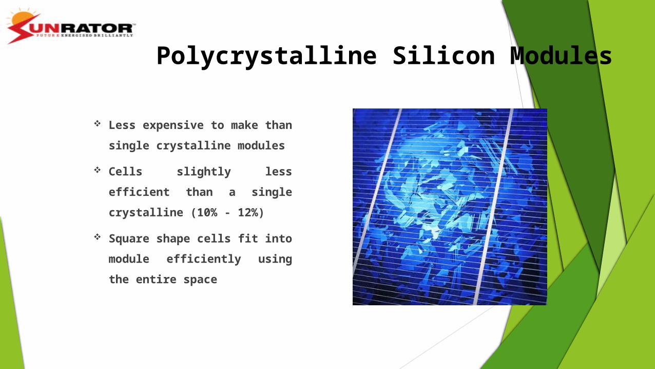
Polycrystalline Silicon Modules
Polycrystalline Silicon Modules
Less expensive to make than
single crystalline modules
Cells slightly less efficient than
a single crystalline (10% - 12%)
Square shape cells fit into
module efficiently using the
entire space

PV Module (Single crystal, Poly crystalline Silicon)Single crystal Poly crystalline
120W(25.7V, 4.7A)
1200mm
800mm800mm
1200mm(3.93ft)
( 2.62ft)
( 3.93f)
(2.62ft)
128W(26.5V ,4.8A)
Efficiency is higher Efficiency is lower
Same size

Amorphous Thin Film
Most inexpensive technology to produce
Metal grid replaced with transparent
oxides
Efficiency = 6 – 8 %
Can be deposited on flexible substrates
Less susceptible to shading problems
Better performance in low light conditions
that with crystalline modules

Solar Panel Manufacturing Technologies Mono-Si Solar Panels Mono-Si is manufactured by Czochralski Process.

Si boule for the production of
wafers.
Solar Panel Manufacturing Technologies Since they are cut from single crystal, they gives the module a uniform appearance.
Advantages
Highest efficient module till now with efficiency between 13 to 21%.
Commonly available in the market.
Greater heat resistance.
Acquire small area where ever placed.
Disadvantages
More expensive to produce.
High amount of Silicon.
High embodied energy (total energy required to produce).

Poly-Si Solar Panels Polycrystalline (or multicrystalline) modules are composed of a number of different
crystals, fused together to make a single cell.
Poly-Si solar panels have a non-uniform texture due to visible crystal grain present due
to manufacturing process.
Advantages Good efficiency between 14 to 16%.
Cost effective manufacture.
Commonly Available in the market.
Visible crystal grain in poly-Si
Solar Panel Manufacturing Technologies

Disadvantages
Not as efficient as Mono-Si.
Large amount of Si.
High Embodied Energy.
Visible difference between Mono-Si and Poly-Si Panels
Mono-Si solar cells are of dark color and the corners of the cells
are usually missing whereas poly-Si panels are of dark or
light blue color. The difference between the structure is only
due to their manufacturing process.
Mono-Si Panel
Poly-Si Panel
Solar Panel Manufacturing Technologies

Thin Film Solar Panels
Made by depositing one or more thin layers (thin film) of
photovoltaic material on a substrate.
Thin Film technology depend upon the type of material
used to dope the substrate.
Cadmium telluride (CdTe), copper indium gallium
selenide (CIGS) and amorphous silicon (A-Si) are three
thin-film technologies often used as outdoor photovoltaic
solar power production.
Solar Panel Manufacturing Technologies

Amorphous-Si Panels Non-crystalline allotrope of Si with no definite arrangement of atoms.
Advantages Partially shade tolerant More effective in hotter climate Uses less silicon - low embodied energy No aluminum frame - low embodied energy
Disadvantages Less efficient with efficiency between 6 to 9% . Less popular - harder to replace. Takes up more space for same output . New technology - less proven reliability.
Solar Panel Manufacturing Technologies

Thin Film Silicon Solar Cells

CdTe/CdS Solar Cell
CdTe: Bandgap 1.5 eV; Absorption coefficient 10 times that of Si
CdS: Bandgap 2.5 eV; Acts as window layer Limitation: Poor contact quality with p-
CdTe (~ 0.1 Wcm2)
Cadmium Telluride Solar Cell
Toxicity of Cd is an issue.
Best lab efficiency = 16.5%.
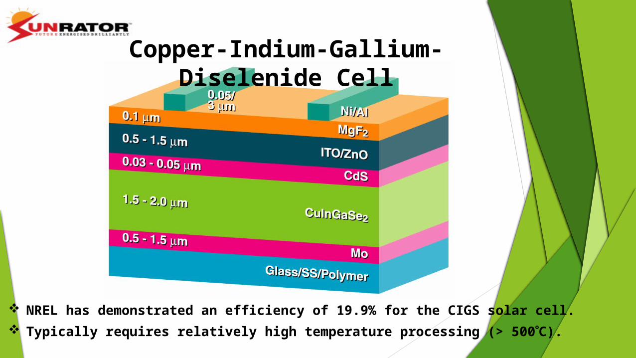
NREL has demonstrated an efficiency of 19.9% for the CIGS solar cell. Typically requires relatively high temperature processing (> 500C).
Copper-Indium-Gallium-Diselenide Cell

Comparison of Si on the basis of crystallinity

Comparison of Mono-Si, Poly-Si and Thin film Panels Mono-Si Panels Poly-Si Panels Thin Film Panels
1. Most efficient with max. efficiency of 21%.
1. Less efficient with efficiency of 16% (max.)
1. Least efficient with max. efficiency of 12%.
2. Manufactured from single Si crystal.
2. Manufactured by fusing different crystals of Si.
2. Manufactured by depositing 1 or more layers of PV material on substrate.
3. Performance best at standard temperature.
3. Performance best at moderately high temperature.
3. Performance best at high temperatures.
4. Requires least area for a given power.
4. Requires less area for a given power.
4. Requires large area for a given power.
5. Large amount of Si hence, high embodied energy.
5. Large amount of Si hence, high Embodied energy.
4. Low amount of Si used hence, low embodied energy.
6. Performance degrades in low-sunlight conditions.
6. Performance degrades in low-sunlight conditions.
5. Performance less affected by low-sunlight conditions.
7. Cost/watt: 1.589 USD 7. 1.418 USD 7. 0.67 USD
8. Largest Manufacturer: Sunpower (USA)
8. Suntech (China) 8. First Solar (USA)

Efficiency, = (VocIscFF)/Pin
Voc is proportional to Eg,
Isc is proportional to # of absorbed
photons
Decrease Eg, absorb more of the
spectrum
But not without sacrificing output
voltage
hv > Eg
Semiconductor Material Efficiencies: The Impact of Band Gap on Efficiency

Direction of current inside PV cell• Inside current of PV cell looks like
“Reverse direction.” Why?
P
N
Current appears to be in the
reverse direction ?
?
• By Solar Energy, current is pumped up from N-pole to P-pole.
• In generation, current appears reverse. It is the same as for battery.
P
NLooks like reverse

Current-Voltage (I-V) Curve
0 exp 1S S
phC Sh
q V IR V IRI I I
kT A R
max,
mp mp OC SCen PV
in PV PV
V IP V I FFP A G A G
RL
+
-
Equivalent circuit of practical PV cell

•Voltage on normal operation point0.5V (in case of Silicon PV)
•Current depend on- Intensity of insolation- Size of cell
(V)
(A)
Voltage(V)
Curr
ent(
I)P
N
A
Short Circuit
Open Circuit
P
N
V
about 0.5V (Silicon)
High insolation
Low insolation
Normal operation point(Maximum Power point)
I x V = W
Open circuit voltage and short circuit current

(V)
(A)
Voltage(V)
Curr
ent(
I)
0.49 V
Standard insolation 1.0 kWh/m2
0.62 V
4.95A
5.55A
Depend ontype of cell or cell-material( Si = 0.5V )
Depend on cell-size
Depend onSolar insolation

To obtain maximum power, current control (or voltage control) is very important.
P
N
A
V
(V)
(A)
Voltage(V)
Curr
ent(
I)
I x V = W
P2
PMAXP1
Vpmax
IpmaxI/V curve
P- Max control
Power curve

(V)
(A)
Voltage(V)
Curr
ent(
I)
12
10
8
6
4
2
00 0.1 0.2 0.3 0.4 0.5 0.6
P
N
A
)(05.0 R
PV characteristics( I/V curve )
If the load has 0.05 ohm resistance, cross point of resistance character and PV-Character will be following point.Then power is 10x0.5=5 W
)(05.0 R
Resistance character
05.0/VI RVI
Ohm’s theory
Estimate obtained power by I / V curve

P
NP
N
Mismatch
5A
1A
P
NP
N
BypassDiode
5A
1A 4A(V)
(A)
Curr
ent(
I)
High intensity insolation
Low intensity insolation
I x V = W
5A
1A
Current is affected largely by change of insolation intensity.
Partially shaded serial cell will produce current mismatch.
I / V curve vs. Insolation intensity
Voltage(V)

Effects of Temperature
As the PV cell temperature
increases above 25º C, the
module Vmp decreases by
approximately 0.5% per
degree C

As insolation decreases amperage decreases while voltage remains roughly constant
Effects of Shading/Low Insolation
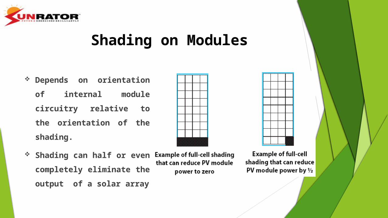
Shading on Modules
Depends on orientation of
internal module circuitry relative
to the orientation of the shading.
Shading can half or even
completely eliminate the output
of a solar array

Series Connections
Loads/sources wired in series
VOLTAGES ARE ADDITIVE CURRENT IS EQUAL

Parallel Connections
Loads/sources wired in parallel:
VOLTAGE REMAINS CONSTANT
CURRENTS ARE ADDITIVE

Roughly size of PV System
How much PV can we install in a given area?
1 kw PV need 10 m2 (108 feet2)Please remember
10m(33feet)
20m
(66f
eet)
Room
Area = 200 m2
(2,178 feet2)
We can install about 20 kW PV

Solar Panel specifications
Mechanical Specifications1. Solar Cell Type: Defines the type of module or cell used in the module.e.g.- Mono-Si, Poly-Si or Thin Film.Design Implication: This determines the class of conversion efficiency of the module.
2. Cell Dimension (in inches/mm.): Defines the size of cell used in the module.e.g.- 125(l) × 125 mm(b) (5 inches).Design Implication: This determines the output power of a single solar cell. 3. Module Dimension (in inches/mm.): Defines the size of the panel.e.g.- 1580 (l)× 808 (b) × 35 (h) mm.Design Implication: Determines the number of cells accommodated in the module.Across length: 1580/125 = 12.64 ~ 12 [least integer]. Across breadth: 808/125 = 6.4 ~ 6.This means number of cell be 72 (6*12).

Solar Panel specificationsMechanical Specifications4. Module Weight (in kgs./lbs.): Defines the weight of the module.e.g.- 15.5 kgs. (34.1 lbs.)Design Implication: Determines the maximum number of panels which can be installed.
5. Glazing or front Glass: Defines the type and width of the front glass used.e.g.- 3.2 mm (0.13 inches) tempered glass.
Design Implication: Width determines the strength of the covering. The type of glass used depends upon thermal insulation requirements or strength requirement.
6. Frame: Defines the type of frame used in the module.e.g.- Anodized aluminium alloy
Design Implication: Frame material is chosen so that it can Withstand the environmental effects such as corrosion, hard Impact etc.

Mechanical Specifications
7. Output Cables: Defines the type of cables and sometimes their dimensions provided at output to connect with connector specifications.e.g.- H+S RADOX® SMART cable 4.0 mm2 of length 1000 mm (39.4 inches) with RADOX® SOLAR integrated twist locking connectors.
Design Implication: The rating of the cable is as per rating of the PV module and of optimum length generally required by the customers.
8. Junction Box: Defines the protection level of electrical casing at the back of panel. Also includes the no. of bypass diodes (if used). e.g.- IP67 rated with 3 bypass diodes.
Solar Panel specifications

Electrical Specifications1. Peak Power (W): Defines the maximum power of the panel.e.g.- P: 195 Wp
2. Optimum operating Voltage: Defines the highest operating voltage of panel at the maximum power at STC.e.g.- Vmp: 36.6VDesign Implication: Determines the number of panels required in series.
3. Optimum operating current: Defines the highest operating current of panel at the maximum power at STC.e.g.- Imp: 5.33ADesign Implication: Determines the wire gauge.Used to calculate the voltage drops across the modules or cells.
Solar Panel specifications

Electrical Specifications
4. Open Circuit Voltage: Defines the output voltage when no load is connected under STC.e.g.- Voc : 45.4VDesign Implication: Determines the maximum possible voltage.Determines the maximum number of modules in series.
5. Short Circuit Current: Defines the protection level of electrical casing at the back of panel. Also includes the no. of bypass diodes (if used). e.g.- Isc: 5.69A Design Implication: Determines the current rating of fuse which is to be used for protection. Determines the conductor size.
Solar Panel specifications

Electrical Specifications7. Module Efficiency: Defines the conversion efficiency given by a given module (which is generally lesser than the single solar cell used in the module). e.g.- 15.3% Design Implication: This parameter helps in solving the problem of choosing a module.
8. Operating Temperature: Defines the range of temperature for which the module can function.e.g.- -40°C to 85°CDesign Implication: Determines the temperature range for the environment in which the panel can be kept.
9. Max. Series Fuse Rating: Defines the max. current which can be handled by the module without damage.e.g.- 15 ADesign Implication: This defines the rating of fuse to be used with the module.
Solar Panel specifications

Electrical Specifications
10. Power Tolerance: Defines the range of power deviation from its stated power ratings due to change in its operating condition. It is defined in %.
e.g.- 0/+5 %Design Implication: This parameter determines the upper limit for power of a module.
11. Parameters defined under NOCT: These parameters are same as defined under STC conditions with different values.
Difference between STC and NOCT:STC (Standard Test Conditions): Irradiance 1000 W/m2, Module temperature 25 °C, Air Mass=1.5
NOCT(Nominal Operating Cell Temperature): Irradiance 800 W/m2, Ambient temperature 20 °C, Wind speed 1 m/s
Solar Panel specifications

Electrical Specifications12. Temperature Coefficients: These coefficients are defined to show the possible rate of
change of values under varying module temperature and irradiance.
Design Implication: These parameters can be used to calculate the power, current and
voltage of the module.
Temperature Coefficient of Voc can also be used to determine the maximum panel voltage
at the lowest expected temperature.
Solar Panel specifications

Parameters at STC Sanyo (HIP-190DA3) Suntech (STP190S-24/Ad+) Trina (TSM-190DC01A)
Optimum Operating Voltage (Vmp) 55.3 V 36.5 V 36.8 V
Optimum Operating Current (Imp) 3.44 A 5.20 A 5.18 A
Open - Circuit Voltage (Voc) 68.1 V 45.2 V 45.1 V
Short - Circuit Current (Isc) 3.7 A 5.62 A 5.52 A
Maximum Power at STC (Pmax) 190 W 190 W 190 W
Module Efficiency 15.7% 14.9% 14.9%
Maximum Series Fuse Rating 15 A 15 A 10 A
Maximum System Voltage 600 VDC 1000 V DC 1000VDC
Power Tolerance +10/-0% 0/+5 % 0/+3
Temperature Coefficient of Pmax -0.34% / °C -0.48 %/°C - 0.45%/°C
Temperature Coefficient of Voc -0.191 V / °C -0.34 %/°C - 0.35%/°C
Temperature Coefficient of Isc 1.68 mA / °C 0.037 %/°C 0.05%/°C
Module Dimension 53.2 x 35.35 x 2.36 in. (1351 x 898 x 60 mm)
62.2 × 31.8 × 1.4 inches (1580 × 808 × 35mm)
62.24 x 31.85 x 1.57in.(1581 x 809 x 40mm)
Warranty : 90% power output 80% power output
20 Years20 Years
12 years 25 years
10 years25 years
Cost: $570.00 $285.00 $459.00
Comparison between Suntech, Trina and Sanyo 190W Monocrystalline modules

Parameters at STC Monocrystalline(S.C. Origin)
Polycrystalline(Moserbaer)
Thin Film (a-si)(China Solar)
Optimum Operating Voltage (Vmp) 17.82V 17 V 18 V
Optimum Operating Current (Imp) 0.285A 0.29A 0.278 A
Open - Circuit Voltage (Voc) 21.396V 21V 26.7 V
Short - Circuit Current (Isc) 0.315A 0.35A 0.401 A
Maximum Power at STC (Pmax) 5W 5 W 5 W
Module Efficiency 16.2% 14% Not Available
Temperature Coefficient of Pmax -0.549% (°K) -0.43 (°K) -(0.19±0.03)%/°C
Temperature Coefficient of Voc -0.397% /°K -0.344 %/°K -(0.34±0.04)%/°C
Temperature Coefficient of Isc 0.06% /°K 0.11 %/ °K 0.08±0.02)%/°C
Maximum System Voltage 1000 VDC 600VDC 600 VDC
Module Dimension 350x176x34mm 359x197x26 mm 385 x322 x18 mm
Warranty: 90% power output 85% power output
10 years25 years
10 years15 years
10 years15 years
Comparison between Mono-, Poly- and Amorphous Si Solar Panels (5 W)

How to choose a solar panel?Critical parameters to be considered for solar panel evaluation
1. Selecting the right technology : The selection of solar panel
technology generally depends on space available for installation
and the overall cost of the system.
2. Selecting the right manufacturer for better warranty.
3. Check operating specifications beyond STC ratings
4. Negative Tolerance can lead to a lower system performance
and reduced capacity.
5. Solar Panel efficiency under different conditions and over time.

Stand-alone systems - those systems which use photovoltaics technology
only, and are not connected to a utility grid.
Hybrid systems - those systems which use photovoltaics and some other
form of energy, such as diesel generation or wind.
Grid-tied systems - those systems which are connected to a utility grid.
Types of Solar Photovoltaic System

Stand Alone PV System

Stand Alone PV SystemWater pumping system

Hybrid PV System

Hybrid PV System
Ranching the Sun project in
Hawaii generates 175 kW of PV
power and 50 kW of wind power
from the five 10 kW wind
turbines
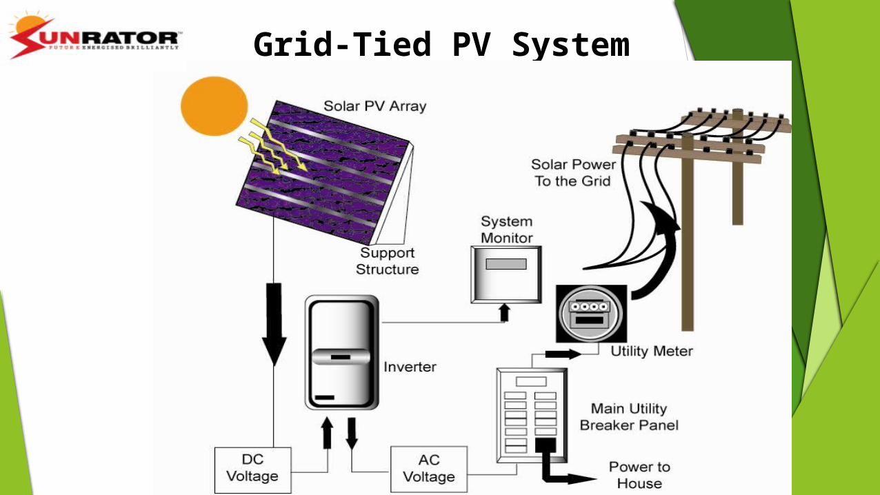
Grid-Tied PV System

Balance of System (BOS)
The BOS typically contains Structures for mounting the PV arrays or modules Power conditioning equipment that massages and
converts the do electricity to the proper form and magnitude required by an alternating current (ac) load.
Sometimes also storage devices, such as batteries, for storing PV generated electricity during cloudy days and at night.

1. Collect some data viz. Latitude of the location, and solar
irradiance (one for every month).
2. Calculation of total solar energy.
3. Estimate the required electrical energy on a
monthly/weekly basis (in kwh):
Required Energy= Equipment Wattage X Usage Time.
4. Calculate the system size using the data from ‘worst
month’ which can be as follows:
a) The current requirement will decide the number of panels
required.
b) The days of autonomy decides the storage capacity of the
system i.e. the number of batteries required.
How to design a PV Off-grid system?

Designing a PV System1. Determine the load (energy, not power)
The load is being supplied by the stored energy device, usually the
battery,
and of the photovoltaic system as a battery charger.
2. Calculating the battery size, if one is needed
3. Calculate the number of photovoltaic modules required
4. Assessing the need for any back-up energy of flexibility for load growth

Determining Load
The appliances and devices (TV's, computers, lights, water pumps etc.) that
consume electrical power are called loads.
Important : examine power consumption and reduce power needs as much
as possible.
Make a list of the appliances and/or loads to be run from solar electric
system.
Find out how much power each item consumes while operating.
Most appliances have a label on the back which lists the Wattage.
Specification sheets, local appliance dealers, and the product
manufacturers are other sources of information.

Determining Loads II
Calculate AC loads (and DC if necessary)
List all AC loads, wattage and hours of use per week (Hrs/Wk).
Multiply Watts by hrs/Wk to get Watt-hours per week (WH/Wk).
Add all the watt hours per week to determine AC Watt Hours Per Week.
Divide by 1000 to get kW-hrs/week

Decide how much storage is provided by battery bank as per requirement (0 if grid tied) expressed as "days of autonomy" because it is based on the number of
days the system should provide power without receiving an input charge from the solar panels or the grid.
Also consider usage pattern and critical nature of application. Alternatively, if a solar panel array is added as a supplement to a generator
based system, the battery bank can be slightly undersized since the generator can be operated in needed for recharging.
Determining the Batteries

Once the storage capacity has been determined, consider the following key parameters: Amp hours, temperature multiplier, battery size and number
To get Amp hours : daily Amp hours number of days of storage capacity ( typically 5 days no input ) 1 x 2 = A-hrs needed Note: For grid tied – inverter losses
Determining the Batteries

Determining Battery Size
Determine the discharge limit for the batteries ( between 0.2 - 0.8 )
Deep-cycle lead acid batteries should never be completely discharged,
an acceptable discharge average is 50% or a discharge limit of 0.5
Divide A-hrs/week by discharge limit
Determine A-hrs of battery and # of batteries needed - Round off to the next
highest number.
This is the number of batteries wired in parallel needed.

Divide system voltage ( typically 12, 24 or 48 ) by battery voltage.
This is the number of batteries wired in series needed.
Multiply the number of batteries in parallel by the number in series.
This is the total number of batteries needed.
Total Number of Batteries Wired in Series

Determining the Number of PV Modules
First find the Solar Irradiance at the location.
Irradiance is the amount of solar power striking a given area and is a measure of the
intensity of the sunshine.
PV engineers use units of Watts (or kiloWatts) per square meter (W/m2) for
irradiance.
http://rredc.nrel.gov/solar/old_data/nsrdb/

Peak Sun Hours
Peak sun hours is defined as the equivalent number of
hours per day, with solar irradiance equaling 1,000 W/m2,
that gives the same energy received from sunrise to
sundown.
Peak sun hours only make sense because PV panel power
output is rated with a radiation level of 1,000W/m2.
Many tables of solar data are often presented as an average
daily value of peak sun hours (kW-hrs/m2) for each month.

Determine total A-hrs/day and increase by 20% for battery losses then
divide by “1 sun hours” to get total Amps needed for array
Then divide your Amps by the Peak Amps produced by your solar module
The peak amperage can be determined if the module's wattage is
dividedby the peak power point voltage
Determine the number of modules in each series string needed to supply
necessary DC battery Voltage
Then multiply the number (for A and for V) together to get the amount of
power you need
P=IV [W]=[A]x[V]
Calculating Energy Output of a PV Array

Charge Controller
Charge controllers are included in most PV systems to protect the batteries
from overcharge and/or excessive discharge.
The minimum function of the controller is to disconnect the array when
the battery is fully charged and keep the battery fully charged without
damage.
The charging routine is not the same for all batteries: a charge controller
designed for lead-acid batteries should not be used to control NiCd
batteries.
Size by determining total Amp max for the array.

Wiring
Selecting the correct size and type of wire will enhance the
performance and reliability of the PV system.
The size of the wire must be large enough to carry the maximum
current expected without undue voltage losses.
All wire has a certain amount of resistance to the flow of current.
This resistance causes a drop in the voltage from the source to the
load. Voltage drops cause inefficiencies, especially in low voltage
systems ( 12V or less ).
See wire size charts here: www.solarexpert.com/Photowiring.html

Inverters
For AC grid-tied systems you do not need a battery or
charge controller if the back up power is not needed–
just the inverter.
The Inverter changes the DC current stored in the
batteries or directly from the PV into usable AC
current.
To size increase the Watts expected to be used by
AC loads running simultaneously by 20%

Off-Grid Design Example
Step 1: Determine the DC Load
DC Device Device Watts
Hours of daily use
DC Watt-hrs per Day (Device Watts x Hours of daily use)
Refrigerator 60 24 1440Lighting fixtures 150 4 600Device A 12 8 96 Total DC Watt-hrs/Day = 2,136

Total AC Watt-hrs/Day = 1,440Divided by 0.85 (Inverter, losses)Total DC Whrs/Day = 1,694
AC Device Device Watts
Hours of daily use
AC Watt-hrs per Day (Device Watts x Hours of daily use)
Device B 6175 6 1050
Pump 80 0.5 40Television 175 2 350 Total AC Watt-hrs/Day = 1440
Step 2: Determine the AC Load, Convert to DC

Step 3: Determine the Total System LoadTotal DC Loads [A] 2,136Total DC Loads [B] 1,694Total System Load 3,830 Whrs/Day
Step 4: Determine Total DC Amp-hours/Day
Total System Load / System Nominal Voltage =(3,830 Whrs/Day) / 12 Volts = 319 Amp-hrs/Day
Step 5: Determine Total Amp-hr/Day with Batteries
Total Amp-hrs/Day X 1.2(Losses and safety factor)319 Amp-hrs/Day X 1.2 = 382.8 or 383 Amp-hrs/Day

Step 6: Determine Total PV Array Current
Total Daily Amp-hr requirement / Design Insolation*=383 Amp-hrs / 5.0 peak solar hrs = 76.6 Amps
* Insolation Based on Optimum Tilt for Season
Step 7: Select PV Module Type
Choose BP Solar-Solarex MSX-60 module:Max Power = 60 W (STP)Max Current = 3.56 AmpsMax Voltage = 16.8 VoltsNominal Output Voltage 12 Volts

Total PV Array Current / (Module Operating Current) X (Module Derate Factor)= 76.6 Amps / (3.56 Amps/Module)(0.90) = 23.90 modules
= (Use 24 Modules)
Step 8: Determine Number of Modules in Parallel
Step 9: Determine Number of Modules in Series
System Nominal Voltage / Module Nominal Voltage12 Volts / (12 Volts/module) = 1 Module
Step 10: Determine Total Number of Modules
Number of modules in parallel X Number of modules in Series= 24 X 1 = 24 modules

Step 11: Determine Minimum Battery Capacity
[Total Daily Amp-hr/Day with Batteries (Step 5)X Desired Reserve Time (Days)] / Percent of Usable Battery Capacity
=(383 Amp-hrs/Day X 3 Days) / 0.80 = 1,436 Amp-hrs
Step 12: Choose a Battery
Use an Interstate U2S – 100 Flooded Lead Acid BatteryNominal Voltage = 6 VoltsRated Capacity = 220 Amp-hrs

Step 13: Determine Number of Batteries in Parallel
Required Battery Capacity (Step 11) / Capacity of Selected Battery=1,436 Amp-hrs / (220 Amp-hrs/Battery) = 6.5 (Use 6 Batteries)
Step 14: Determine Number of Batteries in Series
Nominal System Voltage / Nominal Battery Voltage= 12 Volts / (6 Volts/Battery) = 2 Batteries
Step 15: Determine Total Number of Batteries
Number of Batteries in Parallel X Number of Batteries in Series=6 X 2 = 12 Batteries

Series: Voltage is additive
Parallel: Current is additive
+
-
+
- -+
3 A12 V
3 A12 V 3 A
24 V
6 A12 V
3 A12 V
3 A12 V
+ +
- -
+-

Step 17: Complete Balance of System
a. Complete the design by specifying the:Charge ControllerInverterWire Sizes (Battery will have larger gage due to higher currents)Fuses and DisconnectsStandby Generator, if needed Battery Charger, if neededManual Transfer Switch, if needed.
b. Determine mounting method:Roof mountGround mount with racksGround mount with pole.
c. Assure proper grounding for safety.d. Obtain permits as required.
Step 16: Determine the need for a Standby Generator to reduce other Components (number of Modules and Batteries). Several iterations may be necessary to optimize costs.

Advantage
1.It is free, clean and non-polluting
2.It is a renewable and sustainable energy
3.Solar cells do not produce noise and they are totally silent.
4.Provide electricity to remote places
5.High power-to-weight ratio
6.They require very little maintenance
7.They are long lasting sources of energy which can be used almost anywhere
8.They have long life time
9.There are no fuel costs or fuel supply problems

Disadvantage
1.Soar power can be obtained in night time
2.Soar cells (or) solar panels are Less efficient and very expensive
3.Energy has not be stored in batteries
4.Reliability Depends On Location
5.Environmental Impact of PV Cell Production
6.Air pollution and whether can affect the production of electricity
7.They need large are of land to produce more efficient power supply.
8. Solar energy is a diffuse source.

USES OF SOLAR ENERGY
Heaters Green houses Cars water pumps Lights Desalination Satellites Chilling Dryers Solar ponds Calculators Thermal
Commercial use
On an office building , roof areas can be covered with solar panels . Remote buildings such as schools , communities can make use of
solar energy. In developing countries , this solar panels are very much useful. Even on the highways , for every five kilometres ,solar telephones are
used.

Solar Map of India
About 5,000 trillion kWh per year energy is incident over India’s land area with most parts receiving 4-7 kWh per square meter per day.


