Download - Flow forming of thin-walled precision shells
Flow forming of thin-walled precision shells
BIKRAMJIT PODDER1, PRABAS BANERJEE2, K RAMESH KUMAR1 and
NIRMAL BARAN HUI2,*
1Defence Research and Development Laboratory (DRDL), Kanchanbagh, Hyderabad, India2National Institute of Technology (NIT), Durgapur, India
e-mail: [email protected]; [email protected]; [email protected];
MS received 6 November 2017; revised 28 May 2018; accepted 7 July 2018; published online 27 November 2018
Abstract. Flow forming is an innovative form of cold and chipless metal forming process, used for the
production of high precision, thin-walled, net-shaped cylindrical components. During this process, the length of
a thick walled tube, commonly known as a preform, is increased with a simultaneous decrease in the thickness of
the preform without any change in the internal diameter. Forming of the preform is carried out with the help of
one or more rollers over a rotating mandrel. By a pre-determined amount of thickness reduction in one or more
number of forming passes, the work material is plastically deformed in the radial direction by compression and
made to flow in an axial direction. The desired geometry of the workpiece is achieved when the outer diameter
and the wall of the preform are decreased, and the available material volume is forced to flow longitudinally over
the mandrel. Over the last three and a half decades the flow forming technology has undergone several
remarkable advancements. The versatility of the process makes it possible to produce a wide variety of axi-
symmetric, nearer to the net-shape tubular parts with a complex profile using minimum tooling changes. In this
review article, process details of flow forming have been elaborated. The current state-of-the-art process has
been described, and future developments regarding research and industrial applications are also reviewed.
Keywords. Flow forming; spinning; thin-walled; tooling; power; force; defects.
1. Introduction
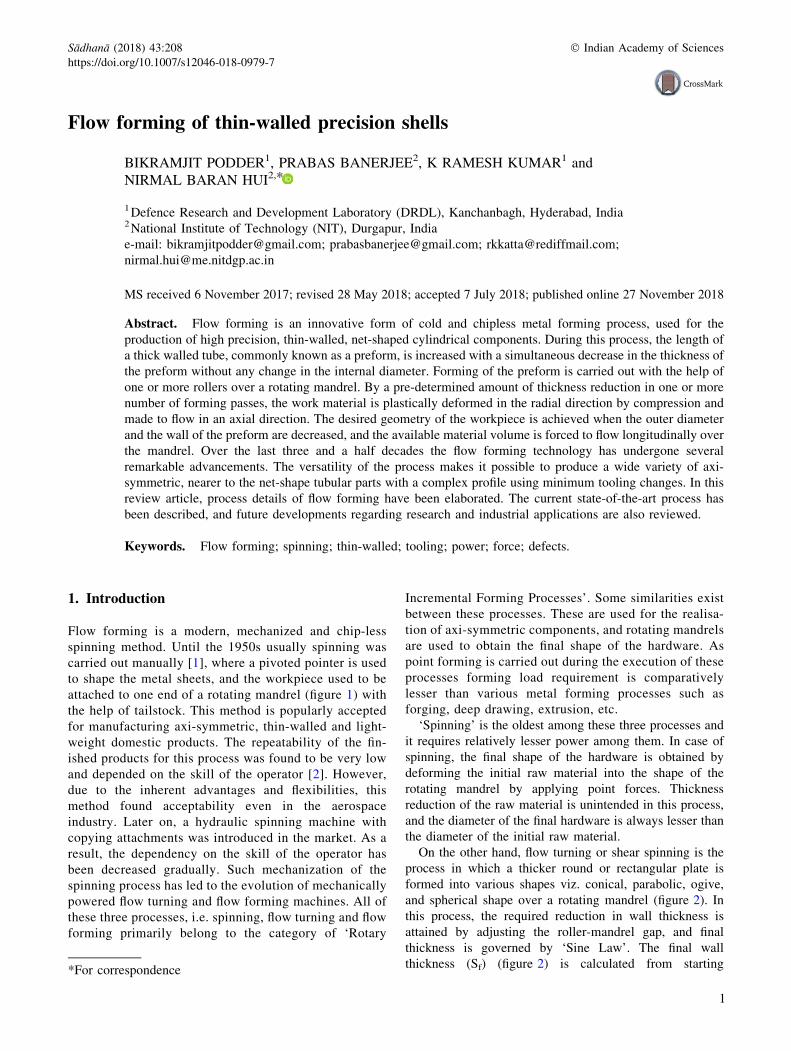
Flow forming is a modern, mechanized and chip-less
spinning method. Until the 1950s usually spinning was
carried out manually [1], where a pivoted pointer is used
to shape the metal sheets, and the workpiece used to be
attached to one end of a rotating mandrel (figure 1) with
the help of tailstock. This method is popularly accepted
for manufacturing axi-symmetric, thin-walled and light-
weight domestic products. The repeatability of the fin-
ished products for this process was found to be very low
and depended on the skill of the operator [2]. However,
due to the inherent advantages and flexibilities, this
method found acceptability even in the aerospace
industry. Later on, a hydraulic spinning machine with
copying attachments was introduced in the market. As a
result, the dependency on the skill of the operator has
been decreased gradually. Such mechanization of the
spinning process has led to the evolution of mechanically
powered flow turning and flow forming machines. All of
these three processes, i.e. spinning, flow turning and flow
forming primarily belong to the category of ‘Rotary
Incremental Forming Processes’. Some similarities exist
between these processes. These are used for the realisa-
tion of axi-symmetric components, and rotating mandrels
are used to obtain the final shape of the hardware. As
point forming is carried out during the execution of these
processes forming load requirement is comparatively
lesser than various metal forming processes such as
forging, deep drawing, extrusion, etc.
‘Spinning’ is the oldest among these three processes and
it requires relatively lesser power among them. In case of
spinning, the final shape of the hardware is obtained by
deforming the initial raw material into the shape of the
rotating mandrel by applying point forces. Thickness
reduction of the raw material is unintended in this process,
and the diameter of the final hardware is always lesser than
the diameter of the initial raw material.
On the other hand, flow turning or shear spinning is the
process in which a thicker round or rectangular plate is
formed into various shapes viz. conical, parabolic, ogive,
and spherical shape over a rotating mandrel (figure 2). In
this process, the required reduction in wall thickness is
attained by adjusting the roller-mandrel gap, and final
thickness is governed by ‘Sine Law’. The final wall
thickness (Sf) (figure 2) is calculated from starting*For correspondence
1
Sådhanå (2018) 43:208 � Indian Academy of Sciences
https://doi.org/10.1007/s12046-018-0979-7Sadhana(0123456789().,-volV)FT3](0123456789().,-volV)
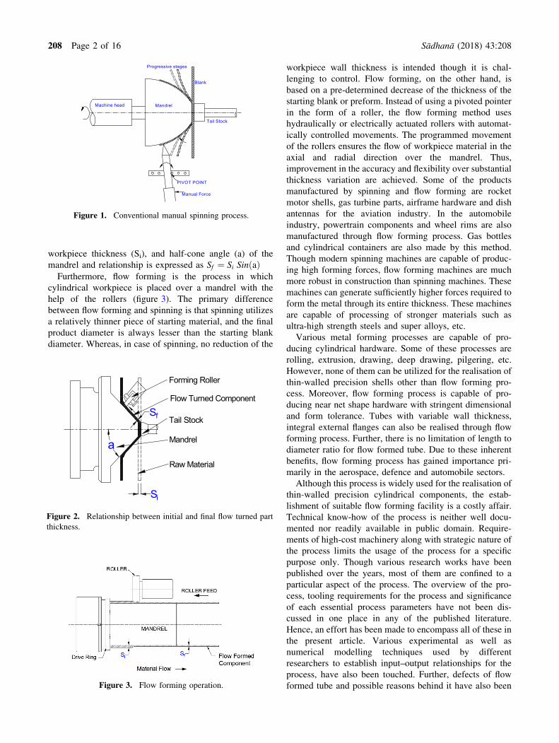
workpiece thickness (Si), and half-cone angle (a) of the
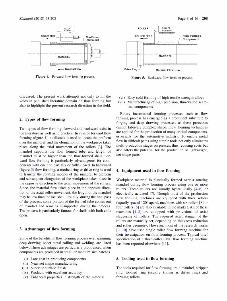
mandrel and relationship is expressed as Sf ¼ Si Sin að ÞFurthermore, flow forming is the process in which
cylindrical workpiece is placed over a mandrel with the
help of the rollers (figure 3). The primary difference
between flow forming and spinning is that spinning utilizes
a relatively thinner piece of starting material, and the final
product diameter is always lesser than the starting blank
diameter. Whereas, in case of spinning, no reduction of the
workpiece wall thickness is intended though it is chal-
lenging to control. Flow forming, on the other hand, is
based on a pre-determined decrease of the thickness of the
starting blank or preform. Instead of using a pivoted pointer
in the form of a roller, the flow forming method uses
hydraulically or electrically actuated rollers with automat-
ically controlled movements. The programmed movement
of the rollers ensures the flow of workpiece material in the
axial and radial direction over the mandrel. Thus,
improvement in the accuracy and flexibility over substantial
thickness variation are achieved. Some of the products
manufactured by spinning and flow forming are rocket
motor shells, gas turbine parts, airframe hardware and dish
antennas for the aviation industry. In the automobile
industry, powertrain components and wheel rims are also
manufactured through flow forming process. Gas bottles
and cylindrical containers are also made by this method.
Though modern spinning machines are capable of produc-
ing high forming forces, flow forming machines are much
more robust in construction than spinning machines. These
machines can generate sufficiently higher forces required to
form the metal through its entire thickness. These machines
are capable of processing of stronger materials such as
ultra-high strength steels and super alloys, etc.
Various metal forming processes are capable of pro-
ducing cylindrical hardware. Some of these processes are
rolling, extrusion, drawing, deep drawing, pilgering, etc.
However, none of them can be utilized for the realisation of
thin-walled precision shells other than flow forming pro-
cess. Moreover, flow forming process is capable of pro-
ducing near net shape hardware with stringent dimensional
and form tolerance. Tubes with variable wall thickness,
integral external flanges can also be realised through flow
forming process. Further, there is no limitation of length to
diameter ratio for flow formed tube. Due to these inherent
benefits, flow forming process has gained importance pri-
marily in the aerospace, defence and automobile sectors.
Although this process is widely used for the realisation of
thin-walled precision cylindrical components, the estab-
lishment of suitable flow forming facility is a costly affair.
Technical know-how of the process is neither well docu-
mented nor readily available in public domain. Require-
ments of high-cost machinery along with strategic nature of
the process limits the usage of the process for a specific
purpose only. Though various research works have been
published over the years, most of them are confined to a
particular aspect of the process. The overview of the pro-
cess, tooling requirements for the process and significance
of each essential process parameters have not been dis-
cussed in one place in any of the published literature.
Hence, an effort has been made to encompass all of these in
the present article. Various experimental as well as
numerical modelling techniques used by different
researchers to establish input–output relationships for the
process, have also been touched. Further, defects of flow
formed tube and possible reasons behind it have also been
MandrelMachine head
Progressive stages
PIVOT POINT
Tail Stock
Blank
Manual Force
Figure 1. Conventional manual spinning process.
Raw Material
Sf
Flow Turned Component
Si
Tail Stock
Mandrela
Forming Roller
Figure 2. Relationship between initial and final flow turned part
thickness.
Figure 3. Flow forming operation.
208 Page 2 of 16 Sådhanå (2018) 43:208
discussed. The present work attempts not only to fill the
voids in published literature domain on flow forming but
also to highlight the present research direction in the field.
2. Types of flow forming
Two types of flow forming; forward and backward exist in
the literature as well as in practice. In case of forward flow
forming (figure 4), a tailstock is used to locate the preform
over the mandrel, and the elongation of the workpiece takes
place along the axial movement of the rollers [3]. The
mandrel supports the flow formed tube and length of
mandrel must be higher than the flow-formed shell. For-
ward flow forming is particularly advantageous for com-
ponents with one end partially or fully closed. In backward
(figure 5) flow forming, a toothed ring or drive ring is used
to transfer the rotating motion of the mandrel to preform
and subsequent elongation of the workpiece takes place in
the opposite direction to the axial movement of the rollers.
Since, the material flow takes place in the opposite direc-
tion of the axial roller movement, the length of the mandrel
may be less than the last shell. Usually, during the final pass
of the process, some portion of the formed tube comes out
of mandrel and remains unsupported during the process.
The process is particularly famous for shells with both ends
open.
3. Advantages of flow forming
Some of the benefits of flow forming process over spinning,
deep drawing, sheet metal rolling and welding, are listed
below. These advantages are particularly pronounced when
components are produced in small or medium size batches.
(i) Low cost in producing components
(ii) Near net shape manufacturing
(iii) Superior surface finish
(iv) Products with excellent accuracy
(v) Enhanced properties in strength of the material
(vi) Easy cold forming of high tensile strength alloys
(vii) Manufacturing of high precision, thin-walled seam-
less components
Rotary incremental forming processes such as flow
forming process has emerged as a prominent substitute to
forging and deep drawing processes, as these processes
cannot fabricate complex shape. Flow forming techniques
are applied for the production of many critical components,
especially for the automotive industry. To enable metal
flow in difficult paths using simple tools not only eliminates
multi-production stages on presses, thus reducing costs but
also offers the potential for the production of lightweight,
net shape parts.
4. Equipment used in flow forming
Workpiece material is plastically formed over a rotating
mandrel during flow forming process using one or more
rollers. These rollers are usually hydraulically [4–6] or
electrically actuated [7]. Though most of the production
flow forming machines are equipped with three rollers
(equally spaced 120� apart), machines with six rollers [8] or
four rollers [6] are also available in the market. All of these
machines [4–8] are equipped with provisions of axial
staggering of rollers. The required axial stagger of the
rollers are manually set, depending on thickness reduction
and roller geometry. However, most of the research works
[9, 10] have used single roller flow forming machine for
their investigation on flow forming process. Typical brief
specification of a three-roller CNC flow forming machine
has been reported elsewhere [11].
5. Tooling used in flow forming
The tools required for flow forming are a mandrel, stripper
ring, toothed ring (usually known as driver ring) and
forming rollers.
Flow FormedComponent
MANDREL
ROLLER FEED
Material Flow
ROLLERHOUSING
Tail
Stoc
k
Figure 4. Forward flow forming process.
ROLLER
Material Flow
MANDREL
Flow FormedComponent
ROLLER FEED
ROLLERHOUSING
Drive Ring
Figure 5. Backward flow forming process.
Sådhanå (2018) 43:208 Page 3 of 16 208
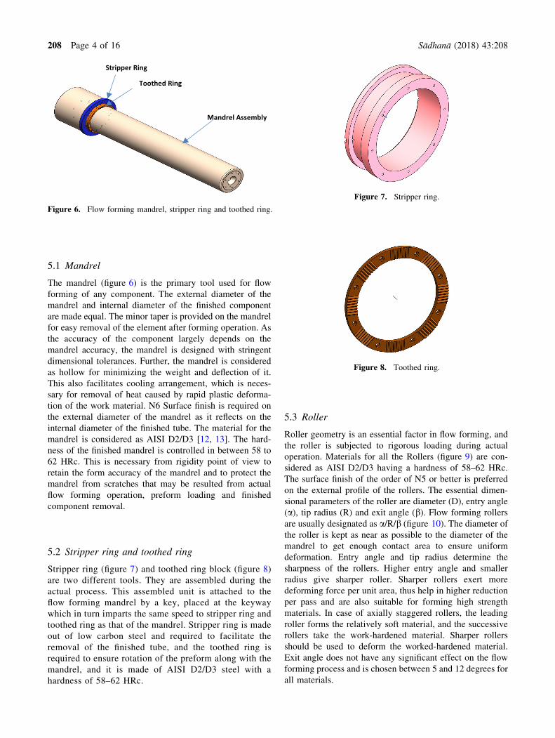
5.1 Mandrel
The mandrel (figure 6) is the primary tool used for flow
forming of any component. The external diameter of the
mandrel and internal diameter of the finished component
are made equal. The minor taper is provided on the mandrel
for easy removal of the element after forming operation. As
the accuracy of the component largely depends on the
mandrel accuracy, the mandrel is designed with stringent
dimensional tolerances. Further, the mandrel is considered
as hollow for minimizing the weight and deflection of it.
This also facilitates cooling arrangement, which is neces-
sary for removal of heat caused by rapid plastic deforma-
tion of the work material. N6 Surface finish is required on
the external diameter of the mandrel as it reflects on the
internal diameter of the finished tube. The material for the
mandrel is considered as AISI D2/D3 [12, 13]. The hard-
ness of the finished mandrel is controlled in between 58 to
62 HRc. This is necessary from rigidity point of view to
retain the form accuracy of the mandrel and to protect the
mandrel from scratches that may be resulted from actual
flow forming operation, preform loading and finished
component removal.
5.2 Stripper ring and toothed ring
Stripper ring (figure 7) and toothed ring block (figure 8)
are two different tools. They are assembled during the
actual process. This assembled unit is attached to the
flow forming mandrel by a key, placed at the keyway
which in turn imparts the same speed to stripper ring and
toothed ring as that of the mandrel. Stripper ring is made
out of low carbon steel and required to facilitate the
removal of the finished tube, and the toothed ring is
required to ensure rotation of the preform along with the
mandrel, and it is made of AISI D2/D3 steel with a
hardness of 58–62 HRc.
5.3 Roller
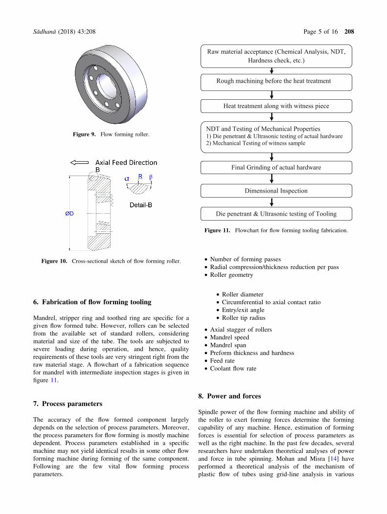
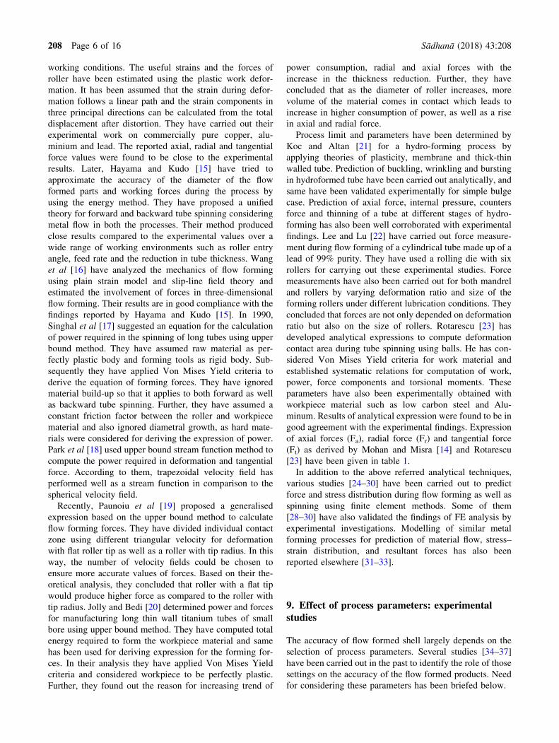
Roller geometry is an essential factor in flow forming, and
the roller is subjected to rigorous loading during actual
operation. Materials for all the Rollers (figure 9) are con-
sidered as AISI D2/D3 having a hardness of 58–62 HRc.
The surface finish of the order of N5 or better is preferred
on the external profile of the rollers. The essential dimen-
sional parameters of the roller are diameter (D), entry angle
(a), tip radius (R) and exit angle (b). Flow forming rollers
are usually designated as a/R/b (figure 10). The diameter of
the roller is kept as near as possible to the diameter of the
mandrel to get enough contact area to ensure uniform
deformation. Entry angle and tip radius determine the
sharpness of the rollers. Higher entry angle and smaller
radius give sharper roller. Sharper rollers exert more
deforming force per unit area, thus help in higher reduction
per pass and are also suitable for forming high strength
materials. In case of axially staggered rollers, the leading
roller forms the relatively soft material, and the successive
rollers take the work-hardened material. Sharper rollers
should be used to deform the worked-hardened material.
Exit angle does not have any significant effect on the flow
forming process and is chosen between 5 and 12 degrees for
all materials.
Figure 7. Stripper ring.
Figure 8. Toothed ring.
Stripper Ring
Mandrel Assembly
Toothed Ring
Figure 6. Flow forming mandrel, stripper ring and toothed ring.
208 Page 4 of 16 Sådhanå (2018) 43:208
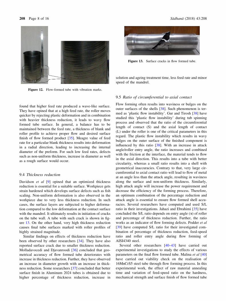
6. Fabrication of flow forming tooling
Mandrel, stripper ring and toothed ring are specific for a
given flow formed tube. However, rollers can be selected
from the available set of standard rollers, considering
material and size of the tube. The tools are subjected to
severe loading during operation, and hence, quality
requirements of these tools are very stringent right from the
raw material stage. A flowchart of a fabrication sequence
for mandrel with intermediate inspection stages is given in
figure 11.
7. Process parameters
The accuracy of the flow formed component largely
depends on the selection of process parameters. Moreover,
the process parameters for flow forming is mostly machine
dependent. Process parameters established in a specific
machine may not yield identical results in some other flow
forming machine during forming of the same component.
Following are the few vital flow forming process
parameters.
• Number of forming passes
• Radial compression/thickness reduction per pass
• Roller geometry
• Roller diameter
• Circumferential to axial contact ratio
• Entry/exit angle
• Roller tip radius
• Axial stagger of rollers
• Mandrel speed
• Mandrel span
• Preform thickness and hardness
• Feed rate
• Coolant flow rate
8. Power and forces
Spindle power of the flow forming machine and ability of
the roller to exert forming forces determine the forming
capability of any machine. Hence, estimation of forming
forces is essential for selection of process parameters as
well as the right machine. In the past few decades, several
researchers have undertaken theoretical analyses of power
and force in tube spinning. Mohan and Misra [14] have
performed a theoretical analysis of the mechanism of
plastic flow of tubes using grid-line analysis in various
Figure 9. Flow forming roller.
Figure 10. Cross-sectional sketch of flow forming roller.
Raw material acceptance (Chemical Analysis, NDT, Hardness check, etc.)
Rough machining before the heat treatment
Heat treatment along with witness piece
NDT and Testing of Mechanical Properties 1) Die penetrant & Ultrasonic testing of actual hardware2) Mechanical Testing of witness sample
Final Grinding of actual hardware
Dimensional Inspection
Die penetrant & Ultrasonic testing of Tooling
Figure 11. Flowchart for flow forming tooling fabrication.
Sådhanå (2018) 43:208 Page 5 of 16 208
working conditions. The useful strains and the forces of
roller have been estimated using the plastic work defor-
mation. It has been assumed that the strain during defor-
mation follows a linear path and the strain components in
three principal directions can be calculated from the total
displacement after distortion. They have carried out their
experimental work on commercially pure copper, alu-
minium and lead. The reported axial, radial and tangential
force values were found to be close to the experimental
results. Later, Hayama and Kudo [15] have tried to
approximate the accuracy of the diameter of the flow
formed parts and working forces during the process by
using the energy method. They have proposed a unified
theory for forward and backward tube spinning considering
metal flow in both the processes. Their method produced
close results compared to the experimental values over a
wide range of working environments such as roller entry
angle, feed rate and the reduction in tube thickness. Wang
et al [16] have analyzed the mechanics of flow forming
using plain strain model and slip-line field theory and
estimated the involvement of forces in three-dimensional
flow forming. Their results are in good compliance with the
findings reported by Hayama and Kudo [15]. In 1990,
Singhal et al [17] suggested an equation for the calculation
of power required in the spinning of long tubes using upper
bound method. They have assumed raw material as per-
fectly plastic body and forming tools as rigid body. Sub-
sequently they have applied Von Mises Yield criteria to
derive the equation of forming forces. They have ignored
material build-up so that it applies to both forward as well
as backward tube spinning. Further, they have assumed a
constant friction factor between the roller and workpiece
material and also ignored diametral growth, as hard mate-
rials were considered for deriving the expression of power.
Park et al [18] used upper bound stream function method to
compute the power required in deformation and tangential
force. According to them, trapezoidal velocity field has
performed well as a stream function in comparison to the
spherical velocity field.
Recently, Paunoiu et al [19] proposed a generalised
expression based on the upper bound method to calculate
flow forming forces. They have divided individual contact
zone using different triangular velocity for deformation
with flat roller tip as well as a roller with tip radius. In this
way, the number of velocity fields could be chosen to
ensure more accurate values of forces. Based on their the-
oretical analysis, they concluded that roller with a flat tip
would produce higher force as compared to the roller with
tip radius. Jolly and Bedi [20] determined power and forces
for manufacturing long thin wall titanium tubes of small
bore using upper bound method. They have computed total
energy required to form the workpiece material and same
has been used for deriving expression for the forming for-
ces. In their analysis they have applied Von Mises Yield
criteria and considered workpiece to be perfectly plastic.
Further, they found out the reason for increasing trend of
power consumption, radial and axial forces with the
increase in the thickness reduction. Further, they have
concluded that as the diameter of roller increases, more
volume of the material comes in contact which leads to
increase in higher consumption of power, as well as a rise
in axial and radial force.
Process limit and parameters have been determined by
Koc and Altan [21] for a hydro-forming process by
applying theories of plasticity, membrane and thick-thin
walled tube. Prediction of buckling, wrinkling and bursting
in hydroformed tube have been carried out analytically, and
same have been validated experimentally for simple bulge
case. Prediction of axial force, internal pressure, counters
force and thinning of a tube at different stages of hydro-
forming has also been well corroborated with experimental
findings. Lee and Lu [22] have carried out force measure-
ment during flow forming of a cylindrical tube made up of a
lead of 99% purity. They have used a rolling die with six
rollers for carrying out these experimental studies. Force
measurements have also been carried out for both mandrel
and rollers by varying deformation ratio and size of the
forming rollers under different lubrication conditions. They
concluded that forces are not only depended on deformation
ratio but also on the size of rollers. Rotarescu [23] has
developed analytical expressions to compute deformation
contact area during tube spinning using balls. He has con-
sidered Von Mises Yield criteria for work material and
established systematic relations for computation of work,
power, force components and torsional moments. These
parameters have also been experimentally obtained with
workpiece material such as low carbon steel and Alu-
minum. Results of analytical expression were found to be in
good agreement with the experimental findings. Expression
of axial forces (Fa), radial force (Fr) and tangential force
(Ft) as derived by Mohan and Misra [14] and Rotarescu
[23] have been given in table 1.
In addition to the above referred analytical techniques,
various studies [24–30] have been carried out to predict
force and stress distribution during flow forming as well as
spinning using finite element methods. Some of them
[28–30] have also validated the findings of FE analysis by
experimental investigations. Modelling of similar metal
forming processes for prediction of material flow, stress–
strain distribution, and resultant forces has also been
reported elsewhere [31–33].
9. Effect of process parameters: experimentalstudies
The accuracy of flow formed shell largely depends on the
selection of process parameters. Several studies [34–37]
have been carried out in the past to identify the role of those
settings on the accuracy of the flow formed products. Need
for considering these parameters has been briefed below.
208 Page 6 of 16 Sådhanå (2018) 43:208

9.1 Roller radius
Effect of roller radius was studied by Srinivasulu et al [34]
by conducting experiments with different rollers of radius 4
to 15 mm. They observed that ovality of the tube directly
proportional to the roller radius. They opined that less force
is produced with smaller roller radius, resulting in lesser
ovality in the tubes. They also have mentioned that the
increase in the mean diameter of the tube is directly pro-
portional to the roller radius (refer to table 2). According to
them, increase in roller radius increases the radial force
during forming, leading to increasing circumference
dimension and resulting in increased mean diameter. Their
experimental results, i.e., the variation in ovality and
increase in mean diameter with roller radius are presented
in table 2.
9.2 Mandrel speed
Lower mandrel speed produces scratch marks on the tube
surface, whereas higher speed up to a certain limit results in
smooth finish [9]. The finish of flow formed shell deterio-
rates above specific limiting value of mandrel speed due to
vibrations at higher speed (figure 12). Davidson et al [9]
observed the phenomenon in their experimental studies.
They have found that higher mandrel speed unifies the
surface avoiding few defects on the surface. At extreme
high-speed machine generated vibration leading to
decreased surface qualities. They have further opined that
enormous increase in speed leads to increase in adiabatic
temperature of the preform, causing plastic instability of the
material.
9.3 Feed rate
Srinivasulu et al [34] carried out experiments by varying
the feed rates. During their studies, they found that lower
feed rates resulted into tubes with larger inner diameter.
They opined that at lower feed rate plastic deformation in
an axial direction is slower than the radial direction. This
leads to material deformation in the radial direction com-
pared to axial, resulting in an opening of the internal
diameter of the tube. Davidson et al [9] have carried out
experiments with different feed rates. They have further
Table 2. Variation of ovality and mean diameter for different
roller radius [34].
Roller radius Ovality Mean diameter
4 0.10 42.10
8 0.45 43.50
10 0.86 43.80
12 1.32 44.30
15 0.98 45.50
Table 1. Expression of forces as derived by researchers [14, 23].
Mohan and Mishra [14] ti—Initial thickness
of the preform
(mm)
Ft ¼ ti � tf
� �XfXKcX 2nþ1
nþ1tf—Final thickness
of the preform
(mm)
Fr ¼ ti � tf� �
X 1� k3s
� � ffiffiffiffiffiffi2Rftana
qXKcX 2nþ1
nþ1
f—Feed rate (mm/
rev)
Fa ¼ ti � tf
� �X 1� k
3s
� � ffiffiffiffiffiffiffiffiffiffiffiffiffiffiffiffi2Rftana
pXKcX 2nþ1
nþ1a—Roller entry
angle
� ¼ 3ln titf
n—Strain hardening
exponent of raw
material
s ¼ 1� ti
tf
� �Kc—Strength co-
efficient of raw
material
k ¼ titf
� �tan / R—Roller radius
(mm)
Rotarescu [23] At—Projected area
of deformation
volume in
tangential plane
Ft ¼ kAt 4þpþ2mð Þ 2qsinþfð Þsinhcosh�2x1½ �12q
Ar—Projected area
of deformation
volume in radial
plane
Fr ¼kAr 4þpþ2mð Þ 2z1þ2qcosþ
ffiffiffiffiffiffiffiffiffiffiffi4q2�f 2
p� �
12q
Aa—Projected area
of deformation
volume in axial
plane
Fa ¼ kAa 4þpþ2mð Þ 2y1þ2qsincosh�fð Þ12q
k—Shear flow stress
m—Shear friction
co-efficient
q—Contact
deformation
pressure
a—Roller entry
angle
f—Feed rate
h—Angle of outer
helical trajectory/
halix angle
x1, y1, z1—The
distance of
highest point of
the deformation
arc (located on
work piece outer
surface) from the
roller centre when
measured along
tangential plane,
axial plane and
radial plane
respectively
Sådhanå (2018) 43:208 Page 7 of 16 208
found that higher feed rate produced a wave-like surface.
They have opined that at a high feed rate, the roller moves
quicker by rejecting plastic deformation and in combination
with heavier thickness reduction, it leads to wavy flow
formed tube surface. In general, a balance has to be
maintained between the feed rate, a thickness of blank and
roller profile to achieve proper flow and desired surface
finish of flow formed product [35]. Meagre value of feed
rate for a particular blank thickness results into deformation
in a radial direction, leading to increasing the internal
diameter of the preform. For such low feed rates, defects
such as non-uniform thickness, increase in diameter as well
as a rough surface would occur.
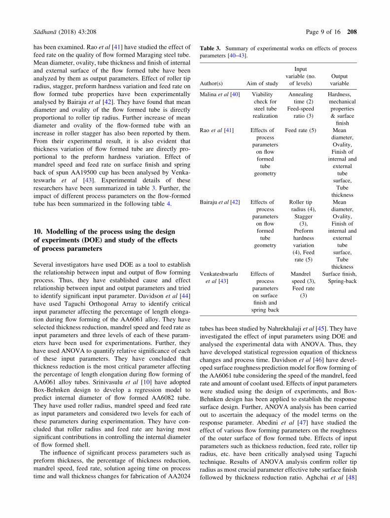
9.4 Thickness reduction
Davidson et al [9] opined that an optimized thickness
reduction is essential for a suitable surface. Workpiece gets
strain hardened which develops surface defects such as fish
scaling. Non-uniform deformation is also observed in the
workpiece due to very less thickness reduction. In such
cases, the surface layers are subjected to higher deforma-
tion compared to the low deformation at the contact surface
with the mandrel. It ultimately results in initiation of cracks
on the tube wall. A tube with such crack is shown in fig-
ure 13. On the other hand, very high thickness reduction
causes final tube surfaces marked with roller profiles of
highly strained magnitude.
Similar findings on effects of thickness reduction have
been observed by other researchers [34]. They have also
reported surface crack due to smaller thickness reduction.
Molladavocedi and Djavanroodi [36] concluded that geo-
metrical accuracy of flow formed tube deteriorates with
increase in thickness reduction. Further, they have observed
an increase in diameter growth with an increase in thick-
ness reduction. Some researchers [37] concluded that better
surface finish in Aluminum 2024 tubes is obtained due to
higher percentage of thickness reduction, increase in
solution and ageing treatment time, less feed rate and minor
speed of the mandrel.
9.5 Ratio of circumferential to axial contact
Flow forming often results into waviness or bulges on the
outer surfaces of the shells [38]. Such phenomenon is ter-
med as ‘plastic flow instability’. Gur and Tirosh [38] have
studied this ‘plastic flow instability’ during tub spinning
process and observed that the ratio of the circumferential
length of contact (S) and the axial length of contact
(L) under the roller is one of the critical parameters in this
regard. The plastic flow instability which results in wavy
bulges on the outer surface of the finished component is
influenced by this ratio [38]. With an increase in attack
angle/roller entry angle, the ratio increases and combined
with the friction at the interface, the material tends to flow
in the axial direction. This results into a tube with better
circularity, whereas a small ratio results into a shell with
geometrical inaccuracies. Contrary to that, very large cir-
cumferential to axial contact ratio will lead to flow of metal
at an angle less than the attack angle, resulting in waviness
along the surface and non-uniform thickness. Similarly,
high attack angle will increase the power requirement and
decrease the efficiency of the forming process. Therefore,
an optimum combination of the percentage reduction and
attack angle is essential to ensure flow formed shell accu-
racies. Several researchers have computed and used S/L
ratio in their investigations. Jahazi and Ebrahimi [35] have
concluded the S/L ratio depends on entry angle (a) of rollerand percentage of thickness reduction. Further, the ratio
works as an indicator of flow forming defects. Podder et al
[39] have computed S/L ratio for their investigated com-
bination of percentage of thickness reduction, feed-speed
ratio and roller entry angle during flow forming of
AISI4340 steel.
Several other researchers [40–43] have carried out
experimental investigations to study the effects of various
parameters on the final flow formed tube. Malina et al [40]
have carried out viability check on the realisation of
16MnCrS5 steel tube through flow forming process. In this
experimental work, the effect of raw material annealing
time and variation of feed-speed ratio on the hardness,
mechanical strength and surface finish of flow formed tube
Figure 12. Flow-formed tube with vibration marks.
Figure 13. Surface cracks in flow formed tube.
208 Page 8 of 16 Sådhanå (2018) 43:208
has been examined. Rao et al [41] have studied the effect of
feed rate on the quality of flow formed Maraging steel tube.
Mean diameter, ovality, tube thickness and finish of internal
and external surface of the flow formed tube have been
analyzed by them as output parameters. Effect of roller tip
radius, stagger, preform hardness variation and feed rate on
flow formed tube properties have been experimentally
analysed by Bairaju et al [42]. They have found that mean
diameter and ovality of the flow formed tube is directly
proportional to roller tip radius. Further increase of mean
diameter and ovality of the flow-formed tube with an
increase in roller stagger has also been reported by them.
From their experimental result, it is also evident that
thickness variation of flow formed tube are directly pro-
portional to the preform hardness variation. Effect of
mandrel speed and feed rate on surface finish and spring
back of spun AA19500 cup has been analysed by Venka-
teswarlu et al [43]. Experimental details of these
researchers have been summarized in table 3. Further, the
impact of different process parameters on the flow-formed
tube has been summarized in the following table 4.
10. Modelling of the process using the designof experiments (DOE) and study of the effectsof process parameters
Several investigators have used DOE as a tool to establish
the relationship between input and output of flow forming
process. Thus, they have established cause and effect
relationship between input and output parameters and tried
to identify significant input parameter. Davidson et al [44]
have used Taguchi Orthogonal Array to identify critical
input parameter affecting the percentage of length elonga-
tion during flow forming of the AA6061 alloy. They have
selected thickness reduction, mandrel speed and feed rate as
input parameters and three levels of each of these param-
eters have been used for experimentations. Further, they
have used ANOVA to quantify relative significance of each
of these input parameters. They have concluded that
thickness reduction is the most critical parameter affecting
the percentage of length elongation during flow forming of
AA6061 alloy tubes. Srinivasulu et al [10] have adopted
Box-Behnken design to develop a regression model to
predict internal diameter of flow formed AA6082 tube.
They have used roller radius, mandrel speed and feed rate
as input parameters and considered two levels for each of
these parameters during experimentation. They have con-
cluded that roller radius and feed rate are having most
significant contributions in controlling the internal diameter
of flow formed shell.
The influence of significant process parameters such as
preform thickness, the percentage of thickness reduction,
mandrel speed, feed rate, solution ageing time on process
time and wall thickness changes for fabrication of AA2024
tubes has been studied by Nahrekhalaji et al [45]. They have
investigated the effect of input parameters using DOE and
analysed the experimental data with ANOVA. Thus, they
have developed statistical regression equation of thickness
changes and process time. Davidson et al [46] have devel-
oped surface roughness prediction model for flow forming of
the AA6061 tube considering the speed of the mandrel, feed
rate and amount of coolant used. Effects of input parameters
were studied using the design of experiments, and Box-
Behnken design has been applied to establish the response
surface design. Further, ANOVA analysis has been carried
out to ascertain the adequacy of the model terms on the
response parameter. Abedini et al [47] have studied the
effect of various flow forming parameters on the roughness
of the outer surface of flow formed tube. Effects of input
parameters such as thickness reduction, feed rate, roller tip
radius, etc. have been critically analysed using Taguchi
technique. Results of ANOVA analysis confirm roller tip
radius as most crucial parameter effective tube surface finish
followed by thickness reduction ratio. Aghchai et al [48]
Table 3. Summary of experimental works on effects of process
parameters [40–43].
Author(s) Aim of study
Input
variable (no.
of levels)
Output
variable
Malina et al [40] Viability
check for
steel tube
realization
Annealing
time (2)
Hardness,
mechanical
properties
& surface
finish
Feed-speed
ratio (3)
Rao et al [41] Effects of
process
parameters
on flow
formed
tube
geometry
Feed rate (5) Mean
diameter,
Ovality,
Finish of
internal and
external
tube
surface,
Tube
thickness
Bairaju et al [42] Effects of
process
parameters
on flow
formed
tube
geometry
Roller tip
radius (4),
Stagger
(3),
Preform
hardness
variation
(4), Feed
rate (5)
Mean
diameter,
Ovality,
Finish of
internal and
external
tube
surface,
Tube
thickness
Venkateshwarlu
et al [43]
Effects of
process
parameters
on surface
finish and
spring back
Mandrel
speed (3),
Feed rate
(3)
Surface finish,
Spring-back
Sådhanå (2018) 43:208 Page 9 of 16 208
have investigated the effect of percentage of thickness
reduction, the feed rate of roller and roller tip radius on the
diametric growth during flow forming of AISI 321 steel tube.
They have used Response SurfaceMethodology to develop a
mathematical model of diametric growth concerning sig-
nificant input parameters. They concluded that the percent-
age of thickness reduction is the most significant parameter
whereas the feed rate is having the minimum effect on dia-
metric growth.
Different researchers [9, 49–52] have applied various
Design of Experiment (DOE) techniques for modelling of
flow formed as well as other rotary incremental forming
process. Chen et al [49] have used Taguchi method for
optimization of inner rib thickness during simulation of the
neck-in process of the AA6061-T6 alloy. They have used
mandrel support span, mandrel speed, feed rate and roller
diameter as input/control variable and adopted S/N ratio,
response chart and average response chart method for
optimization of the inner rib. Razani et al [50] have used
Taguchi method for optimization of out of roundness of
flow formed AISI321 steel tube. They have used feed rate,
thickness reduction and roller entry angle as input param-
eter and attempted to minimize out of roundness of flow
formed AISI 321 steel tube. Same authors [51] have sub-
sequently used Response Surface Method (RSM) to opti-
mize hardness of flow formed AISI 321 steel tube.
Modeling of a paraxial spinning process using Taguchi
method has been attempted by Guo et al [52]. They have
tried to predict outer diameter, surface finish and the final
thickness of flow formed Ni-based superalloy tube con-
sidering roller tip radius, mandrel speed and feed rate as
input parameters. Davidson et al [9] have modelled hard-
ness of flow formed and artificially aged AA 6061 tube
using Response Surface Method considering solutionising
time, ageing time and ageing temperature as input param-
eters in their model. A summary of the research studies
[9, 49–52] are presented in table 5.
11. Modelling of the process using finite elementmethods (FEM) and study of the effectsof the process parameters
Considerable research has been carried out on modeling of
flow forming process using FEM, and some of them have
been described in this section. Wong et al [53] used explicit
FE to analyse the forming of solid cylindrical preform using
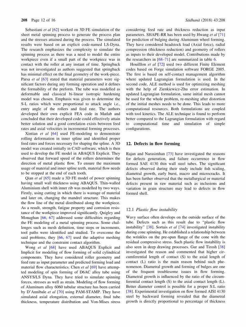
Table 5. Summary of application of DOE approaches on flow forming and similar rotary incremental process [9, 49–52].
Author(s) Aim of study
DOE
methods
Input variable (no. of
levels for each) Output variable Evaluation method
Chen et al
[49]
Optimization of rib
thickness during neck-in
spinning process
Taguchi
method
Mandrel span, Mandrel
speed, feed rate and
diameter (3)
Rib thickness S/N ratio, response
chart, average
response chart
Razani
et al
[50]
Optimization of out of
roundness
Taguchi
method
Feed rate, Thickness
reduction, Roller entry
angle (3)
Out of roundness of flow
formed AISI321 steel
tube
ANOVA
Razani
et al
[51]
Optimization of hardness Response
surface
method
Mandrel speed, Feed rate,
Thickness reduction (2)
Hardness of flow formed
AISI 321 steel tube
ANOVA
Guo et al
[52]
Modelling of paraxial
spinning process
Taguchi
method
Roller tip radius, Mandrel
speed, Feed rate (3)
Outer diameter, surface
finish and final
thickness
ANOVA
Davidson
et al [9]
Modelling of hardness of
artificially aged tube
Response
surface
method
Solution time, aging time
and temperature (2)
Hardness of flow
formed, artificially
aged AA6061 tube
ANOVA
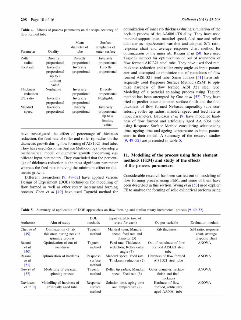
Table 4. Effects of process parameters on the shape accuracy of
flow formed tube.
Parameter Ovality
Mean
diameter of
tube
Surface
roughness of
outer surface
Roller
radius
Directly
proportional
Directly
proportional
Inversely
proportional
Feed rate Inversely
proportional
up to a
limiting
value
Inversely
proportional
Directly
proportional
Thickness
reduction
Negligible Inversely
proportional
Directly
proportional
S/L ratio Inversely
proportional
Inversely
proportional
Negligible
Mandrel
speed
Inversely
proportional
Directly
proportional
Inversely
proportional
up to a
limiting
value
208 Page 10 of 16 Sådhanå (2018) 43:208

ABAQUS software and analyzed the effect of mass scaling
on dynamic properties of the process. The following
assumptions were considered by them in the model to
reduce computational complexity:
• The workpiece material was assumed to be an
elastoplastic material.
• Roller and mandrel both were modelled as rigid part
geometries.
• The work-piece rotation was not considered.
• The roller was rotated around the axis of the rotating
workpiece with the similar speed as in the experimen-
tal process.
• The friction between the workpiece and roller was
assumed as the friction factor l, which they have
defined as f = k= r/H3 where f is the shear stress, k is
the shear strength, and r is the flow stress of the
material.
The model proposed by Wong et al [53] was successful
in predicting the stress and strain generated during the
forming process. The authors also concluded that the rollers
geometry plays a dominating role in shaping the deformed
product, but work-piece with an initial thickness of 10 mm
needs higher machine capability and high mandrel rigidity
to avoid any bulging phenomenon. The assumption made in
the research work can be implemented in solving complex
flow forming problems. Li et al [54] developed a 3D FE
program to model the stress–strain effects in the deforma-
tion zone in tube spinning. The tube was modelled to rotate
along with the mandrel, and the rollers were given axial
feed. The results obtained were used in determining the
ovality and bell mouth defects related to tube spinning.
Song et al [55] have studied the diametric growth of tube
during forward flow forming process using commercial FE
implicit code, DEFORMTM 3D V10.0. They have carried
out an experimental investigation as well as finite element
simulation using implicit investigation scheme. AA6061
and SS304 have been considered as experimental material,
and residual stresses of the formed products were measured
using X-ray diffraction technique. They could obtain good
agreement between the simulation and experimental results.
Cho et al [56] have developed an approximate finite ele-
ment analysis model for simulation of flow forming pro-
cess. They have considered two fixed artificial planes of
symmetry and constrained their analysis domain within
them. Two analysis domains of 1/24th and 1/8th of full
domain size have been considered, and simulation results
were compared with the experimental results. Though the
results of an artificial plan of symmetry were found to be
entirely different, results of midplane region were found to
be in good agreement with the experimental results. Fur-
ther, they have opined that predictions of a 1/24th domain
model are more reliable as it has been built with finer mesh
system. Shinde et al [57] have used ABAQUS/explicit to
develop a 3D thermo-mechanical finite element model for
reverse flow forming of a cylindrical workpiece made up of
maraging steel. They have studied the effect of feed rate
and thickness reduction ratio on stress/strain distribution
and roller forces. Further, they have carried out a para-
metric study to ascertain the effect of process parameters on
ovality, diametral growth, roll forces, stress and strains.
They have concluded that feed rate, thickness reduction
ratio and roller entry angle are the most significant
parameters controlling the circularity of the flow formed
tube.
Novella et al [58] have developed an optimised finite
element based model for numerical simulation of flow
forming of AlSi7 alloy at elevated temperature. Implicit
solution scheme with an arbitrary Lagrangian-Eulerian
meshing has been adopted during the development of the
model. The influences of input process parameters such as
thickness reduction, feed rate and mandrel speed have been
studied, and finally, an algorithm for derivation of para-
metric process chart has been proposed.
Hauk et al [59] implemented both 2D and 3D FE analysis
for the simulation of both flow splitting process considering
disk type workpiece. For the 2D model, an axi-symmetric
method was assumed and compared the results obtained
from the commercial FE-code through DEFORM-3D and
MARC/Autoforge. The approach adopted by the authors
can efficiently solve axi-symmetric problems (for example,
rolling of billet with two rollers).
Hua et al [60] made a three-dimensional elasto-plastic
FE analyses with the help of ANSYS software of three
roller backward tube flow forming. The authors were suc-
cessful in establishing the contact pair not only between
workpiece and rollers but also between mandrel and
workpiece. It was suggested that the rollers feed rate, the
speed of the mandrel and thickness reduction are the pri-
mary process parameters and complex state of axial and
circumferential stresses formed in the flow formed tubes
leads to surface cracks. According to their report, the
influence of feed rates was found to be maximum for flow-
forming of AA7075 tubes.
Razavi et al [61] used ABAQUS explicit 6.4 to simulate
the spinning process. The following assumptions were
considered in their study to reduce the computational
complexity.
• The friction coefficient between a tool and the
workpiece interface was assumed as 0.02.
• The frictionless interface was assumed between the
workpiece and mandrel.
• The tailstock was not considered in the simulation to
reduce computational time. The blank was segregated
into two separate cells using a central cylindrical cell
of radius 26.5 mm and constrained to the mandrel.
They concluded that hoop and radial strains in FE-sim-
ulations are close to the experimental values of a spinning
process. They also have opined that the stress developed on
the inner surface of the workpiece is very low, but it plays a
significant role in bellmouth formation in tubes.
Sådhanå (2018) 43:208 Page 11 of 16 208
Sebastiani et al [62] worked on 3D FE simulation of the
sheet metal spinning process to generate the process plan
and the stresses attained during the process. The simulated
results were based on an explicit code-named LS-Dyna.
The research emphasizes the complexity to simulate the
spinning process as there was a need to model the entire
workpiece even if a small part of the workpiece was in
contact with the roller at any instant of time. Springback
was not investigated as authors suggested that springback
has minimal effect on the final geometry of the work-piece.
Parsa et al [63] stated that material parameters were sig-
nificant factors during any forming operation and it defines
the formability of the preform. The tube was modelled as
deformable and classical bi-linear isotropic hardening
model was chosen. Emphasis was given to determine the
S-L ratios which were proportional to attack angle i.e.,
entry angle of the rollers and feed rate. The authors
developed their own explicit FEA code in Matlab and
concluded that their developed code could effectively attain
better solution and a good correlation exists between feed
rates and axial velocities in incremental forming processes.
Xintian et al [64] used FE-modeling to demonstrate
rolling deformation in inner spline and identified proper
feed rates and forces necessary for shaping the spline. A 3D
model was created initially in CAD software, which is then
used to develop the FE model in ABAQUS Explicit. They
observed that forward speed of the rollers determines the
direction of metal plastic flow. To ensure the maximum
usage of material and inner spline teeth, material flow needs
to be stopped at the end of each tooth.
Qian et al [65] made a 3D FE model of power spinning
having small wall thickness using ABAQUS. Thin-walled
Aluminium shell with inner rib was modelled by two ways.
Firstly, using cutting in which there is wastage of material
and later on, changing the mandrel structure. This makes
the flow line of the metal distributed along the workpiece.
As a result, strength, fatigue property and corrosion resis-
tance of the workpiece improved significantly. Quigley and
Monaghan [66, 67] addressed some difficulties regarding
the FE modeling of a metal spinning process. Some chal-
lenges such as mesh definition, time steps or increments,
tool paths were identified and studied. To overcome the
said problems, they [66, 67] used the adaptive meshing
technique and the constraint contact algorithm.
Wong et al [68] have used ABAQUS Explicit and
Implicit for modeling of flow forming of solid cylindrical
components. They have considered roller geometry and
feed rate as input parameter and predicted forming load and
material flow characteristics. Chen et al [69] have attemp-
ted modeling of spin forming of D6AC alloy tube using
ANSYS/LS Dyna. They have tried to simulate spinning
forces, stresses as well as strain. Modeling of flow forming
of Aluminum alloy 6060 tubular structure has been carried
by D’Annibale et al [70] using PAM-STAMP. They have
simulated axial elongation, external diameter, final tube
thickness, temperature distribution and Von-Mises stress
considering feed rate and thickness reduction as input
parameters. SHAPE-RR has been used by Hwang et al [71]
for prediction of bulging during Aluminum wheel forming.
They have considered headstock load (Axial force), radial
compression (thickness reduction) and geometry of rollers
as inputs to their developed model. Contributions made by
the researchers in [68–71] are summarized in table 6.
Houilllon et al [72] used two different Finite Element
codes based on Forge simulation software FORGE 2005.
The first is based on self-contact management algorithm
where updated Lagrangian formulation is used. In the
second code, ALE method is used for optimizing meshing
with the help of Zienkiewicz-Zhu error estimation. In
updated Lagrangian formulation, same initial mesh cannot
be used for the whole problem, re-meshing after distortion
of the initial meshes needs to be done. This leads to more
computational resources. Both formulations are coupled
with tool kinetics. The ALE technique is found to perform
better compared to the Lagrangian formulation with regard
to computational time and simulation of simple
configurations.
12. Defects in flow forming
Rajan and Narasimhan [73] have investigated the reasons
for defects generation, and failure occurrence in flow
formed SAE 4130 thin wall steel tubes. The significant
defects observed during their study include fish scaling,
diametral growth, early burst, macro and microcracks. It
has been further observed that the metallurgical or material
defects present in raw material such as inclusions and
variation in grain structure may lead to defects in flow
formed shell.
12.1 Plastic flow instability
Wavy surface often develops on the outside surface of the
tube. Defects such as this result due to ‘‘plastic flow
instability’’ [38]. Sortais et al [74] investigated instability
during cone spinning. He established a relationship between
the wrinkles on the pre-spun flange of the cone with the
residual compressive stress. Such plastic flow instability is
also seen in deep drawing processes. Gur and Tirosh [38]
investigated the reason and commented that higher cir-
cumferential length of contact (S) to the axial length of
contact (L) ratio is the main reason behind such phe-
nomenon. Diametral growth and forming of bulges are one
of the frequent troublesome issues in flow forming.
Diametral growth is influenced by the ratio of the circum-
ferential contact length (S) to the axial contact length (L).
Better diameter control is possible for a proper S:L ratio
[38]. Experimental investigation on flow formed AISI 4130
steel by backward forming revealed that the diametral
growth is directly proportional to percentage of thickness
208 Page 12 of 16 Sådhanå (2018) 43:208
reduction. Though mandrel can be undersized to counter
the effect of diametric growth, minimization of the dia-
metric growth by controlling S:L ratio is an improved
technique.
12.2 Cracking
Rajan and Narasimhan [73] have observed cracks in flow
formed SAE4130 shell subsequent to pressure testing and
dimensional accuracy check. Long, sharp, longitudinal
through wall crack was observed during such cases.
Inclusions at hard particle boundary results into huge stress
concentrations and subsequently when such tube is sub-
jected to 90% thickness reduction without any intermediate
annealing, de-cohesion in mechanical bond is observed
between particle and matrix. Such de-cohesion leads to
cracking of flow formed tube. Further, few internal cracks
were also observed on the mandrel side of tube surface for
few hardened and tempered preforms. They opined that
large number of inclusions present in the non-electro-slag
refined raw material causes such cracks. Under such tensile
stresses, inclusions serve as initiation sites leading to crack
formation during forming or subsequent pressure testing.
Such failures are similar to central burst as observed by
Kalpakjian and Rajagopal [75].
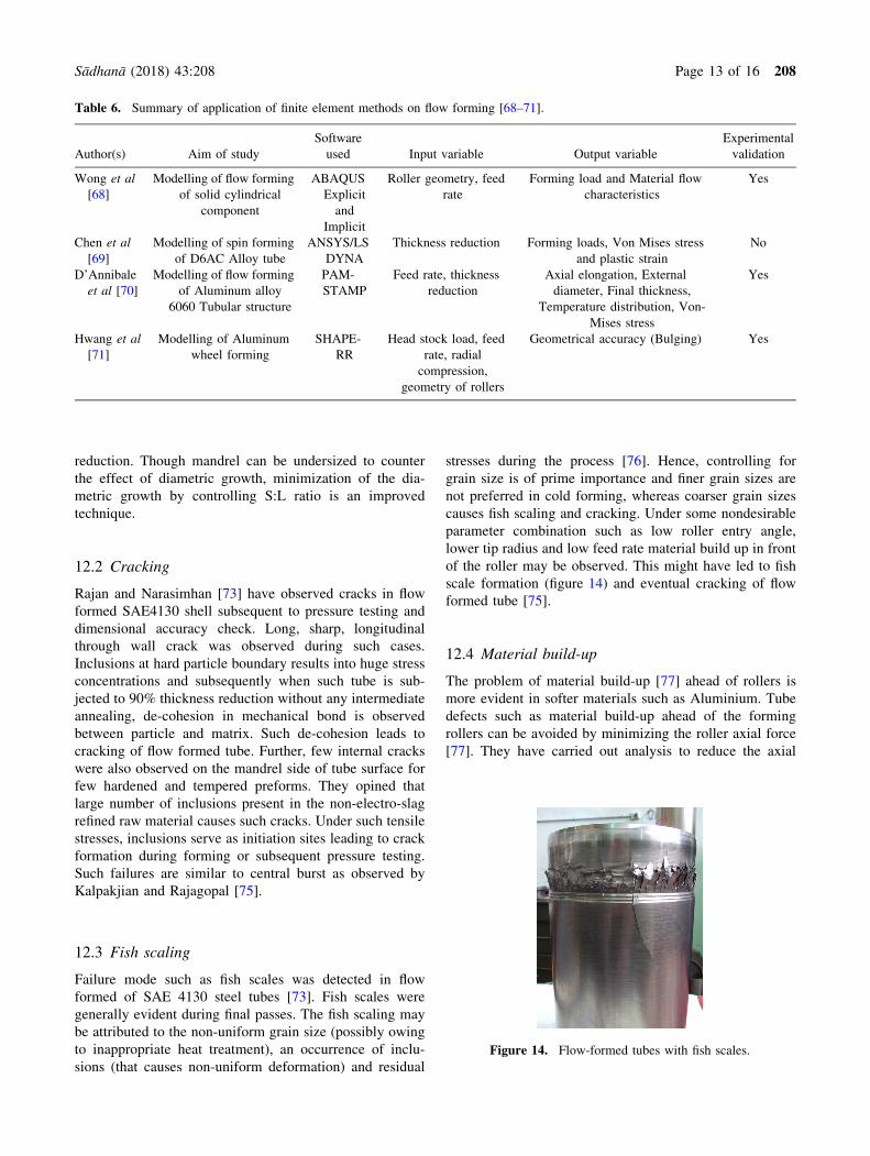
12.3 Fish scaling
Failure mode such as fish scales was detected in flow
formed of SAE 4130 steel tubes [73]. Fish scales were
generally evident during final passes. The fish scaling may
be attributed to the non-uniform grain size (possibly owing
to inappropriate heat treatment), an occurrence of inclu-
sions (that causes non-uniform deformation) and residual
stresses during the process [76]. Hence, controlling for
grain size is of prime importance and finer grain sizes are
not preferred in cold forming, whereas coarser grain sizes
causes fish scaling and cracking. Under some nondesirable
parameter combination such as low roller entry angle,
lower tip radius and low feed rate material build up in front
of the roller may be observed. This might have led to fish
scale formation (figure 14) and eventual cracking of flow
formed tube [75].
12.4 Material build-up
The problem of material build-up [77] ahead of rollers is
more evident in softer materials such as Aluminium. Tube
defects such as material build-up ahead of the forming
rollers can be avoided by minimizing the roller axial force
[77]. They have carried out analysis to reduce the axial
Figure 14. Flow-formed tubes with fish scales.
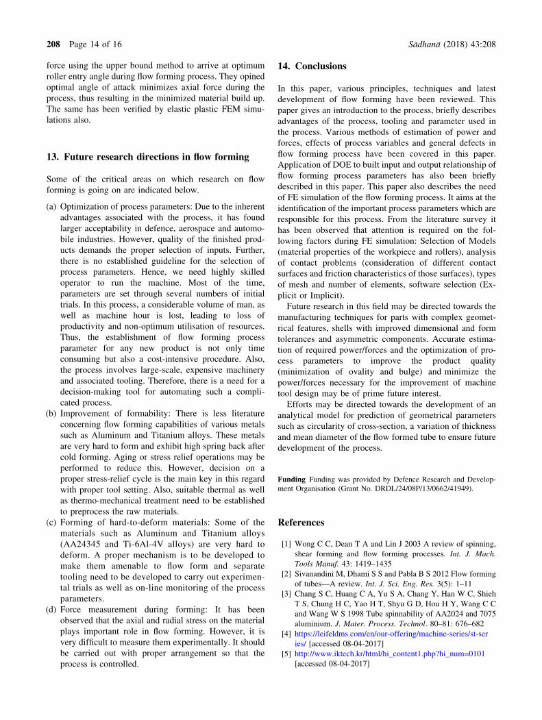
Table 6. Summary of application of finite element methods on flow forming [68–71].
Author(s) Aim of study
Software
used Input variable Output variable
Experimental
validation
Wong et al
[68]
Modelling of flow forming
of solid cylindrical
component
ABAQUS
Explicit
and
Implicit
Roller geometry, feed
rate
Forming load and Material flow
characteristics
Yes
Chen et al
[69]
Modelling of spin forming
of D6AC Alloy tube
ANSYS/LS
DYNA
Thickness reduction Forming loads, Von Mises stress
and plastic strain
No
D’Annibale
et al [70]
Modelling of flow forming
of Aluminum alloy
6060 Tubular structure
PAM-
STAMP
Feed rate, thickness
reduction
Axial elongation, External
diameter, Final thickness,
Temperature distribution, Von-
Mises stress
Yes
Hwang et al
[71]
Modelling of Aluminum
wheel forming
SHAPE-
RR
Head stock load, feed
rate, radial
compression,
geometry of rollers
Geometrical accuracy (Bulging) Yes
Sådhanå (2018) 43:208 Page 13 of 16 208
force using the upper bound method to arrive at optimum
roller entry angle during flow forming process. They opined
optimal angle of attack minimizes axial force during the
process, thus resulting in the minimized material build up.
The same has been verified by elastic plastic FEM simu-
lations also.
13. Future research directions in flow forming
Some of the critical areas on which research on flow
forming is going on are indicated below.
(a) Optimization of process parameters: Due to the inherent
advantages associated with the process, it has found
larger acceptability in defence, aerospace and automo-
bile industries. However, quality of the finished prod-
ucts demands the proper selection of inputs. Further,
there is no established guideline for the selection of
process parameters. Hence, we need highly skilled
operator to run the machine. Most of the time,
parameters are set through several numbers of initial
trials. In this process, a considerable volume of man, as
well as machine hour is lost, leading to loss of
productivity and non-optimum utilisation of resources.
Thus, the establishment of flow forming process
parameter for any new product is not only time
consuming but also a cost-intensive procedure. Also,
the process involves large-scale, expensive machinery
and associated tooling. Therefore, there is a need for a
decision-making tool for automating such a compli-
cated process.
(b) Improvement of formability: There is less literature
concerning flow forming capabilities of various metals
such as Aluminum and Titanium alloys. These metals
are very hard to form and exhibit high spring back after
cold forming. Aging or stress relief operations may be
performed to reduce this. However, decision on a
proper stress-relief cycle is the main key in this regard
with proper tool setting. Also, suitable thermal as well
as thermo-mechanical treatment need to be established
to preprocess the raw materials.
(c) Forming of hard-to-deform materials: Some of the
materials such as Aluminum and Titanium alloys
(AA24345 and Ti-6Al-4V alloys) are very hard to
deform. A proper mechanism is to be developed to
make them amenable to flow form and separate
tooling need to be developed to carry out experimen-
tal trials as well as on-line monitoring of the process
parameters.
(d) Force measurement during forming: It has been
observed that the axial and radial stress on the material
plays important role in flow forming. However, it is
very difficult to measure them experimentally. It should
be carried out with proper arrangement so that the
process is controlled.
14. Conclusions
In this paper, various principles, techniques and latest
development of flow forming have been reviewed. This
paper gives an introduction to the process, briefly describes
advantages of the process, tooling and parameter used in
the process. Various methods of estimation of power and
forces, effects of process variables and general defects in
flow forming process have been covered in this paper.
Application of DOE to built input and output relationship of
flow forming process parameters has also been briefly
described in this paper. This paper also describes the need
of FE simulation of the flow forming process. It aims at the
identification of the important process parameters which are
responsible for this process. From the literature survey it
has been observed that attention is required on the fol-
lowing factors during FE simulation: Selection of Models
(material properties of the workpiece and rollers), analysis
of contact problems (consideration of different contact
surfaces and friction characteristics of those surfaces), types
of mesh and number of elements, software selection (Ex-
plicit or Implicit).
Future research in this field may be directed towards the
manufacturing techniques for parts with complex geomet-
rical features, shells with improved dimensional and form
tolerances and asymmetric components. Accurate estima-
tion of required power/forces and the optimization of pro-
cess parameters to improve the product quality
(minimization of ovality and bulge) and minimize the
power/forces necessary for the improvement of machine
tool design may be of prime future interest.
Efforts may be directed towards the development of an
analytical model for prediction of geometrical parameters
such as circularity of cross-section, a variation of thickness
and mean diameter of the flow formed tube to ensure future
development of the process.
Funding Funding was provided by Defence Research and Develop-
ment Organisation (Grant No. DRDL/24/08P/13/0662/41949).
References
[1] Wong C C, Dean T A and Lin J 2003 A review of spinning,
shear forming and flow forming processes. Int. J. Mach.
Tools Manuf. 43: 1419–1435
[2] Sivanandini M, Dhami S S and Pabla B S 2012 Flow forming
of tubes—A review. Int. J. Sci. Eng. Res. 3(5): 1–11
[3] Chang S C, Huang C A, Yu S A, Chang Y, Han W C, Shieh
T S, Chung H C, Yao H T, Shyu G D, Hou H Y, Wang C C
and Wang W S 1998 Tube spinnability of AA2024 and 7075
aluminium. J. Mater. Process. Technol. 80–81: 676–682
[4] https://leifeldms.com/en/our-offering/machine-series/st-ser
ies/ [accessed 08-04-2017]
[5] http://www.iktech.kr/html/hi_content1.php?hi_num=0101
[accessed 08-04-2017]
208 Page 14 of 16 Sådhanå (2018) 43:208

[6] http://mjcengineering.com/machines/flow-forming-
machines/mjc-f450-2000-4/ [accessed 08-04-2017]
[7] www.denn.es/index.php/en/technologies/flow-forming [ac-
cessed 08-04-2017]
[8] http://www.repkon.com.tr/en/machines-flow-forming.html
[accessed 08-04-2017]
[9] DavidsonM J, Balasubramanian K and Tagore GRN 2008An
experimental study on the quality of flow-formed AA6061
tubes. J. Mater. Process. Technol. 203(1–3): 321–325
[10] Srinivasulu M, Komaraiah M and Prasada Rao C S K 2012
Experimental investigations to predict mean diameter of the
AA6082 tube in flow forming process—A DOE approach.
IOSR J. Eng. (IOSRJEN), 2(6): 52–60
[11] Podder B, Mondal C, Gopi G, Ramesh Kumar K and Yadav
D R 2011 Effect of cold flow forming deformation on the
tensile properties of 15CrMoV6 steel. In: Proceeding of 2011
International Conference on Mechanical and Aerospace
Engineering (CAME 2011), New Delhi, India, pp. 604–606
[12] Rajan KM, Deshpande P U and Narasimhan K 2002 Effect of
heat treatment of preform on themechanical properties of flow
formedAISI 4130 steel tubes—A theoretical and experimental
assessment. J. Mater. Process. Technol. 125–126: 503–511
[13] Venkateshwarlu G, Ramesh Kumar K and Janardhan Reddy
T A 2016 Experimental study of flow forming process
parameters on thickness variation of aluminium alloy
AA6061 tubes. Int. J. Lat. Res. Eng. Technol. 2(10): 33–40
[14] Ram Mohan T and Misra R 1970 Studies on power spinning
of tubes. Int. J. Prod. Res. 10(4): 351–364
[15] Hayama M and Kudo H 1979 Analysis of diametrical growth
and working forces in tube spinning. Bull. Jpn. Soc. Mech.
Eng. 22 (167): 776–784
[16] Wang T, Wang Z R, Wang Q, Zhao Y and Wang S 1989 The
slipline fields of thickness-reduction spinning and the engi-
neering calculation of the spinning forces. In: Proceedings of
the Fourth International Conference on Rotary Forming.
135–139: pp. 89–93
[17] Singhal P R, Saxena P K and Prakash R 1990 Estimation of
power in the shear spinning of long tubes in hard-to-work
materials. J. Mater. Process. Technol. 23 (1): 29–40
[18] Park J W, Kim Y H and Bae W B 1997 Analysis of tube
spinning processes by the upper bound stream function
method. J. Mater. Process. Technol. 66 (1–3): 195–203
[19] Paunoiu V, Nicoara D and Teodorescu M 1999 A general
upper bound method for forces calculation in tube spinning
process. In: Proceedings of the Sixth ICTP September 19–24,
Advanced Technology of Plasticity. 1: pp. 109–-1100
[20] Sukhwinder Singh Jolly and Bedi D S 2010 Analysis of
power and forces in the making of long tubes in hard-to-work
materials. In: Proceeding of the world congress on Engi-
neering (WCE), Vol II, London, UK
[21] Muammer Koc and Taylan Altan 2002 Prediction of forming
limits and parameters in the tube hydroforming process. Int.
J. Mach. Tool. Manuf. 42(1): 123–138
[22] Lee K S and Lu L 2001 A study on the flow forming of
cylindrical tubes. J. Mater. Process. Technol. 113(1–3):
739–742
[23] Rotarescu M I 1995 A Theoretical analysis of tube spinning
using balls. J. Mater. Process. Technol. 54(1–4): 224–229
[24] Banerjee P, Kundu R, Singh M, Dubey P K and Hui N B
2016 FE based simulation of forward flow forming process.
Int. J. Res. Mech. Eng. 4(2): 1–5
[25] Mali S and Joshi S S 2015 Three-dimensional simulation of
staggered flow forming process. Int. J. Manu. Technol.
Manag. 29(5–6): 324–346
[26] JIANG Shu-yong, ZHENG Yu-feng, REN Zheng-yi and LI
Chun-feng 2009 Multi-pass spinning of thin-walled tubular
part with longitudinal inner ribs. Trans. Nonferrous Met. Soc.
China 19(1): 215–221
[27] Yang Yu and Xu Hongji 2010 Finite element analysis of
power spinning and spinning force for tube parts. Int. J. Adv.
Sci. Technol. 20: 53–59
[28] Zoghi H, Arezoodar A F and Sayeaftabi M 2013 Enhanced
finite element analysis of material deformation and strain
distribution in spinning of 42CrMo steel tubes at elevated
temperature. Mater. Des. 47: 234–242
[29] Liu C-H 2007 The simulation of the multi-pass and die-less
spinning process. J. Mater. Process. Technol. 192–193:
518–524
[30] Xia Q X, Cheng X Q, Hu Y and Ruan F 2006 Finite element
simulation and experimental investigation on the forming
forces of 3D non-axisymmetrical tubes spinning. Int.
J. Mech. Sci. 48(7): 726–735
[31] Wu W T, Li G J, Tang J P and Altan T 1994 Finite element
analysis of three- dimensional metal flow in cold and hot
forming processes. CIRP Ann. Manuf. Technol. 43(1):
235–239
[32] Mehta B V, Ibrahim A Z, Gunasekera J S and Buijk A 2001
3D flow analysis inside shear and streamlined extrusion dies
for feeder plate design. J. Mater. Process. Technol. 113(1–3):
93–97
[33] Huang L, Zeng R, Zhang X and Li J 2014 Study on plastic
deformation behaviour of hot splitting spinning of TA15
titanium alloy. Mater. Des. 58: 465–474
[34] Srinivasulu M, Komaraiah M and Rao C S K P 2012
Experimental studies on the characteristics of AA6082 flow
formed tubes. J. Mech. Eng. Res. 4(6): 192–198
[35] Jahazi M and Ebrahimi G 2000 The influence of flow-
forming parameters and microstructure on the quality of
D6AC steel. J. Mater. Process. Technol. 103(3): 362–366
[36] Molladavoudi H R and Djavanroodi F 2011 Experimental
study of thickness reduction effects on mechanical properties
and spinning accuracy of aluminium 7075-O, during flow,
forming. Int. J. Adv. Manuf. Technol. 52(9): 949–957
[37] Fazeli A R and Ghoreishi M 2009 Investigation of effective
parameters on surface roughness in thermo-mechanical tube
spinning process. Int. J. Mater. Form. 2(4): 261–270
[38] Gur M and Tirosh J 1982 Plastic flow instability under
compressive loading during shear spinning process. J. Eng.
Ind. 104(1): 17–22
[39] Podder B, Mondal C, Ramesh Kumar K and Yadav D R 2012
Effect of preform heat treatment on the flow formability and
mechanical properties of AISI4340 steel. Mater. Des. 37:
174–181
[40] Malina J, Jirkova H and Masek B 2008 Optimization of
technological parameters of flow forming process. In: Annals
of DAAAM for 2008 & Proceedings of 19th International
DAAAM Symposium, pp. 783–784
[41] Rao L M, Rao T V L N, Ramana M V and Rao C S K P 2008
Study on the Influence of flow forming parameters of
maraging steel tubes. IE(I) J. PR 89: 10–13
[42] Bairaju M K, Kiran Kumar K and Chand K 2016 Opti-
mization of process parameters for the production of
Sådhanå (2018) 43:208 Page 15 of 16 208
seamless rocket motor tube by flow forming process. Int.
J. Innov. Eng. Res. Technol. 3(8): 70–80
[43] Venkateshwarlu G, Ramesh Kumar K, Janardhan Reddy T A
and Gopi G 2013 Experimental investigation on spinning of
aluminium alloy 19500 cup. Int. J. Eng. Sci. Innov. Technol.
(IJESIT) 2(1): 357–363
[44] Davidson M J, Balasubramanian K and Tagore G R N 2008
Experimental investigation on flow-forming of AA6061
alloy—A Taguchi approach. J. Mater. Process. Technol.
200(1–3): 283–287
[45] Fazeli Nahrekhalaji A R, Ghoreishi M and Tashnizi E S 2010
Modelling and investigation of the wall thickness changes
and process time in thermo-mechanical tube spinning process
using design of experiments. Engineering 2: 141–148
[46] Davidson M J, Balasubramanian K and Tagore G R N 2008
Surface roughness prediction of flow-formed AA6061 alloy
by design of experiments. J. Mater. Process. Technol.
202(1–3): 41–46
[47] Abedini A, Ahmadi S R and Doniavi A V 2014 Roughness
optimization of flow formed tubes using the Taguchi method.
Int. J. Adv. Manuf. Technol. 72(5–8): 1009–1019
[48] Jalali Aghchai A, Razani N A and Mollaei Dariani B 2012
Flow forming optimization based on diametral growth using
finite element method and response surface methodology.
Proc. Inst. Mech. Eng. Part B: J. Eng. Manuf. 226(12): 1–11
[49] Chen C, Ou J-H and Hsu C-J 2012 Simulation analysis of
shell aluminium alloy tube for neck-in spinning process.
WSEAS Trans. SYS. 11(8): 385–397
[50] Razani N A, Jalali Aghchai A and Mollaei Dariani B 2011
Experimental study on flow forming process of AISI 321
steel tube using the Taguchi method. Proc. Inst. Mech. Eng.
Part B: J. Eng. Manuf. 225(11): 2024–2031
[51] Razani N A, Abdolhossein Jalali A and Mollaei Dariani B
2014 Flow-forming optimization based on hardness of flow-
formed AISI321 tube using response surface method. Int.
J. Adv. Manuf. Technol. 70(5–8): 1463–1471
[52] Guo X, Li B, Jin K, Wang H, Wan B and Tao J 2017 A
simulation and experiment study on paraxial spinning of Ni-
based superalloy tube. Int. J. Adv. Manuf. Technol.
93(9–12):4399–4407
[53] Wong C C, Danno A, Tong K K and Yong M S 2008 Cold
rotary forming of thin wall component from flat disc blank. J.
Mater. Process. Technol. 208(1–3): 53–62
[54] Li K, Hao N, Lu Y and Xue K 1998 Research on the dis-
tribution of the displacement in backward tube spinning. J.
Mater. Process. Technol. 79(1–3): 185–188
[55] Song X, Fong S F, Oon S R and Danno A 2014 Diametrical
growth in forward flow forming process. Int. J. Adv. Manuf.
Technol. 71(1): 207–217
[56] Cho J, Jung Y, Lee M and Joun M 2014 Computationally effi-
cient finite element model for simulating a chipless flow form-
ing process. Int. J. Mater. Prod. Technol. 48(1–4): 258–269
[57] Sinde H, Mahajan P, Singh A K, Sing R and Narasimhan K
2016 Process modelling and optimization of the staggered
backward flow forming process of maraging steel via finite
element simulations. Int. J. Adv. Manuf. Technol. 87(5–8):
1851–1864
[58] Novella M F, Ghiotti A, Bruschi S and Capuzzo R 2016
Numerical modelling ofAlSi7 tubular components flow formed
at elevated temperature. Key Eng. Mater. 716: 753–761
[59] Hauk S, Altan T and Vazquez V H 2000 Finite element
simulation of the flow splitting-process. J. Mater. Process.
Technol. 98(1): 70–80
[60] Hua F A, Yang Y S and Zhang Y N 2005 Three dimensional
finite element analysis of tube spinning. J. Mater. Process.
Technol. 168(1): 68–74
[61] Razavi H and Biglari F R and Torabkhani A 2005 Study of
strains distribution in spinning process using FE simulation
and experimental work. In: International Congress on
Manufacturing Engineering, Tehran, pp. 1–9
[62] Sebastiani G, Brosius A, Ewers R, Kleiner M and Klimmek
C 2006 Numerical investigation on dynamic effects during
sheet metal spinning by explicit finite element analysis. J.
Mater. Process. Technol. 177(1–3): 401–403
[63] Parsa M H, Pazooki A M A and Ahmadabadi M N 2009 Flow
forming and flow formability simulation. Int. J. Adv. Manuf.
Technol. 42(5): 463–473
[64] Xintian L, Changhong L, Lihui Z, Hu H, Xiaoyong Z and
Xinyi S 2009 The finite element method applying in the flow
forming. In: Proceedings of Computational Intelligence and
Security Conference, pp. 556–558
[65] Qian B, Yang H and Zhan M 2008 Finite element modelling
of power spinning of thin walled shell with hoop inner rib.
Trans. Nonferrous Met. Soc. 18(1): 6–13
[66] Quigley E and Monaghan J 2002 Enhanced finite element
models of metal spinning. J. Mater. Process. Technol.
121(1): 43–49
[67] Quigley E and Monaghan J 2002 The finite element mod-
elling of conventional spinning using multi-domain models.
J. Mater. Process. Technol. 124(3): 360–365
[68] Wong C C, Dean T A and Lin J 2004 Incremental forming of
solid cylindrical components using flow forming principles.
J. Mater. Process. Technol. 153–154: 60–66
[69] Cheng-Shun Chen, Jen-Hsin Ou and Huei-Guo Hu 2012
Simulation analysis of spinning forming of D6AC ultrahigh-
strength low-alloy steel. Int. J. Mech. 6(3): 187–194
[70] D’Annibale A, Di Ilio A, Paoletti A, Paoletti D and Sfarra S
2017 The combination of advanced tools for parameters
investigation and tools maintenance in flow forming process.
Procedia CIRP 59: 144–149
[71] Hwang Y S O, Kim N and Lee C 2015 Numerical investi-
gation of the effect of process parameters during aluminium
wheel flow-forming. J. Mech. Eng. 61(7–8): 471–476
[72] Houillon M, Massoni E, Ramel E and Loge R E 2007 3D
FEM simulation of flow forming process using Lagrangian
and ALE methods. AIP Conf. Proc. 908(1): 257–262
[73] Rajan K M and Narasimhan K 2001 An Investigation of the
development of defects during flow forming of high strength
thin wall steel tubes. Pract. Fail. Anal. 1(5): 69–76
[74] Sortais H C, Kobayashi S and Thomsen E G 1963.
Mechanics of conventional spinning. J. Eng. Ind. 85(4):
346–350
[75] Kalpakjian S and Rajagopal S 1982 Spinning of tubes: A
review. J. Appl. Met. Work. 2(3): 211–223
[76] Dieter G E 1988 Mechanical Metallurgy. UK: McGraw Hill.
3rd ed.
[77] Kim N, Kim H and Jin K 2013 Minimizing the axial force
and the material build-up in the tube flow forming process.
Int. J. Preci. Eng. Manuf. 14 (2): 259–266
208 Page 16 of 16 Sådhanå (2018) 43:208


