1
FLAME ACCELERATION AND DDT: A FRAMEWORK FOR ESTIMATING POTENTIAL
EXPLOSION HAZARDS IN HYDROGEN MIXTURES
Sergey DorofeevFM Global
Prepared for 3rd European Summer School on Hydrogen Safety Belfast, 21-30 July 2008

2
Background
• Confined explosionsInternal loadsPressure increase
• Unconfined explosions• Semi-confined
External loadsBlast waves
Confined and unconfined explosions
Enclosure or duct
Blast wave
PP

3
Background
• H2 releases and transport of H2- mixtures represent significant safety problem
Tubes / ducts– Ventilation systems– Exhaust pipes
Production facilitiesTunnels
• Hydrogen: special attention because of high sensitivity to FA
Confined explosions
PP

4
Background
• Slow subsonic flames – mild hazards to confining structures
• Fast flames (supersonic relative to a fixed observer) and detonations – serious hazard
• Possibility of FA to supersonic speeds limits implementation of mitigation techniques
explosion suppression explosion venting
4 8 12t, s
0.00.40.81.2
0.6 0.8 1.0t, s
02468
10
0.2 0.210102030
ΔP, bar
t, s
Detonation
Fast Flame
Slow Flame
Confined explosions - hazards

5
Background
• Release of hydrogen gas/liquid
• Mixing with air and formation of “Vapor Cloud”
• Ignition and flame propagation• Generation of air blast wave• The problem is to evaluate
blast parameters (P, I) = f(R) and blast effects
Unconfined explosions (VCE)
Blast wave

6
Background
• Amplitudes of pressure waves generated by gaseous explosions depends on flame speed
• There are solutions for P(R), I(R) as a function of flame speed Vf
TNO multi-energy method (ME)Baker-Strehlow-Tang (BST) Kurchatov Institute (KI) method
• The problem is to define flame speed and explosion energy
Unconfined explosions (VCE) – hazards
7
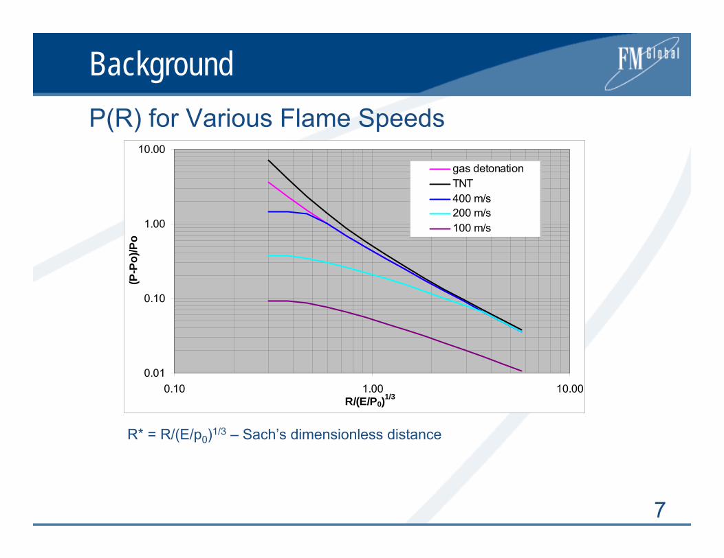
BackgroundP(R) for Various Flame Speeds
R* = R/(E/p0)1/3 – Sach’s dimensionless distance
0.01
0.10
1.00
10.00
0.10 1.00 10.00R/(E/P0)1/3
(P-P
o)/P
o
gas detonationTNT400 m/s200 m/s100 m/s

8
Background
• Explosions almost universally start by ignition of a flame
electrical spark hot surface
• Under certain conditions, flame can accelerate and undergo transition to detonation
• Collectively this process is referred to as deflagration-to-detonation transition (DDT)
• It is important to know critical conditions and resulting flame speeds → loads
Why FA and DDT?

9
Background
• Significant advances made in understanding of FA and DDT
High resolution Schlieren photographyTheoretical and advanced numerical studies
• Basic mechanisms are well understood• Yet there are limitations in predictive simulations
of these complex phenomena• At present time, quantitative predictions typically
rely on experiment based correlations
Understanding of FA and DDT
10
Background
• This lecture presents a framework for estimating potential explosion hazards in hydrogen mixtures
• Emphasis is placed on experimental correlations and analytical models
Basic physicsSimplified models
• Accuracy within a factor of 2
Objective
11
Background
• Few comments on basics of deflagrations and detonations
• Description of FA and DDT • Critical conditions for FA and onset of detonation
FA in smooth tubes FA in ducts with obstaclesEffects of initial/boundary conditions on FAFA in unconfined cloudsOnset of detonations Summary of the framework
• Concluding remarks
Outline

12
Deflagrations
• Weak ignition results in LAMINAR FLAMES
• Propagation mechanism: diffusion of temperature and species
• Laminar burning velocity
• Flame thickness
Laminar flames
srL cS <<∝ τχ
Fraction of reactants
Temperature
Reaction rate
Preheat zone, δ
Reaction zone, δ/β
SL σSL
Reactants Products
Tb
Tu
Y=1
Y=0
L
b
Lu
bb
ST
ST
σχ
ρχρδ )()(
==

13
Deflagrations
• Laminar flames are intrinsically unstable
• Hydrodynamic instability Landau-Darrieus
• Thermal-diffusive instability
Le = χ/DL
Le < 1 – lean H2 flames
Flame instabilities
SL
σSL
ReactantsProducts
t2 >t1t1
ReactantsProducts
t2 >t1t1DL
χ
t1DL
χ
t2 >t1
ReactantsProductsLe<1 Le>1

14
Deflagrations
• Cellular flames in hydrogen mixtures
Cellular flames
Le ≈ 0.35 Le ≈ 1.0 Le ≈ 3.810%H2 in air 10%H2+5%O2+85%Ar 70%H2 in air
15
Deflagrations
• Acoustic-flame instabilities • Kelvin-Helmholtz (K-H) – shear instability• Rayleigh-Taylor (R-T)
Richtmyer-Meshkov (R-M) in compressible flows
• Both K-H and R-T are triggered when flame is accelerated over an obstacle or through a vent
• Powerful mechanisms for ducts with obstacles
More flame instabilities

16
DeflagrationsFlame instabilities
64 m3

17
Deflagrations
• Laminar flames in initially quiescent mixture become turbulent
Development of flame instabilities Growth of turbulence in the flame-generated flow
• Preexisting turbulence
Turbulent flames

18
DeflagrationsFlame in turbulent flow
Reactants Products

19
Deflagrations
• Flow instability results in the development of random oscillations superimposed on mean flow
• r.m.s velocity
• Integral length and time scales LT , τT – size and turnover time of the largest eddies
• Kolmogorov length and time scales: lK , τK – size and turnover time of the smallest eddies
Viscous dissipation occurs at this scale
Scales of turbulence
uuu ′+=
0≡′u
u
tu u′
20
Deflagrations
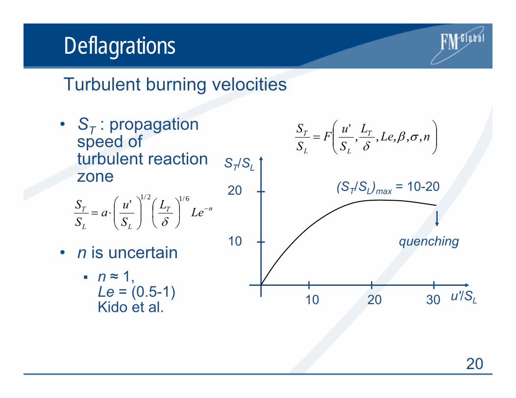
• ST : propagation speed of turbulent reaction zone
• n is uncertainn ≈ 1, Le = (0.5-1)Kido et al.
Turbulent burning velocities
⎟⎟⎠
⎞⎜⎜⎝
⎛= nLeL
SuF
SS T
LL
T ,,,,,' σβδ
ST/SL
u′/SL
10
20
10 20 30
(ST/SL)max = 10-20
quenching
nT
LL
T LeLSua
SS −⎟
⎠⎞
⎜⎝⎛
⎟⎟⎠
⎞⎜⎜⎝
⎛⋅=
6/12/1'
δ

21
Detonations
• 1D detonation waves are unstable and transverse perturbations are formed
• Spacing between transverse waves - detonation cell size λ - is important parameter
• The smaller is λ the more reactive is the mixture
Structure of the front
Smoked foil after CH4/air detonation

22
DDT Phenomenology
• Early detonation studies (1900+) were in smooth tubes using weak ignition
Detonation wave produced at the end of the FA process Flame run-up distance required to form detonation was considered mixture property
• Chapman and Wheeler (1926) were the first to place obstacles in smooth tube to promote FA
• Shchelkin roughened tube by wire coil helix (1940)
Basic studies of DDT
23
DDT Phenomenology
• Stroboscopic Schlieren photographs by Urtiew and Oppenheim (1966) – a milestone in the study of DDT phenomenon
• Photos showed initiation of detonation from local explosion within shock flame complex “explosion in the explosion”
• Simulations of Elaine Oran and colleagues!
Explosion in the explosion

24
DDT PhenomenologyDetonation onset at flame front
25
DDT Phenomenology
• Processes of DDT have been studied in smooth tubes
in channels with repeated obstaclesphotochemical systemshot turbulent jetsshock-flame interactionsother experimental situations
Since that time

26
DDT Phenomenology
• Following Lee & Moen (1980) and Shepherd & Lee (1991), DDT is divided into two phases:
1. Creation of conditions for the onset of detonationby FA, vorticity production, formation of jets, and mixing of products and reactants;
2. Actual formation of detonation itself or the onset of detonation
Phases of DDT process

27
DDT Phenomenology
• Following Lee & Moen (1980) and Shepherd & Lee (1991), DDT is divided into two phases:
1. Creation of conditions for the onset of detonationby FA, vorticity production, formation of jets, and mixing of products and reactants;
2. Actual formation of detonation itself or the onset of detonation
Phases of DDT process
28
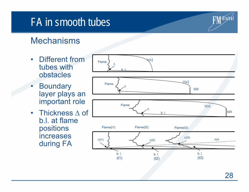
FA in smooth tubes
• Different from tubes with obstacles
• Boundary layer plays an important role
• Thickness Δ of b.l. at flame positions increases during FA
Mechanisms
Flame
Flame
Flame
V(x)
V(x)
V(x)SW
SW
Flame(t1) Flame(t2) Flame(t3)
b. l.
b. l.
b. l. (t1)
b. l. (t2)
b. l. (t3)
Δ(t1) Δ(t2)Δ(t3)
Δ
Δ
Δ
Δ(x)
29
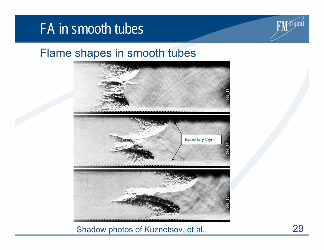
FA in smooth tubesFlame shapes in smooth tubes
Shadow photos of Kuznetsov, et al.
Boundary layer

30
FA in smooth tubes
• Substantial experimental data accumulated on XDDT
• Ambiguous data on the effect of tube diameter and detonation cell size
• Different mechanismsFlame accelerationOnset of detonation
Run-up distances in smooth tubes
V
X
Csp
DCJ
XS XDDT
31
FA in smooth tubes
• We focus on run-up distances to supersonic flamesin relatively smooth tubes
• An approximate analytical model to be described, which is based on the following ideas
Relate flame shape / burning velocity evolution and the flame speedDescribe boundary layer thickness ahead of an accelerated flame
Run-up distances Xs

32
FA in smooth tubes
• Mass balance
• Burning velocity ST
• Boundary layer thickness
• Xs: V+ST = Csp
Xs in smooth tubes
V
ST + V
D
X Δ d
Boundary layer
m
T DDSDV ⎟
⎠⎞
⎜⎝⎛ Δ
−Δ= )1(4
2
σπαπ
6/12/1'
⎟⎠⎞
⎜⎝⎛
⎟⎟⎠
⎞⎜⎜⎝
⎛=
δϕ T
LL
T LSu
SS
Kd
XC +⎟⎠⎞
⎜⎝⎛ Δ
=Δ
ln1κ
⎥⎦
⎤⎢⎣
⎡+⎟
⎠⎞
⎜⎝⎛= KdD
CDX S γ
κγ ln1
3/721
3/1
2)1(
+
⎥⎥⎦
⎤
⎢⎢⎣
⎡⎟⎠⎞
⎜⎝⎛
−=
m
L
sp
DSc δ
σβγ
γ = Δ/D:
Two unknown parameters: m and β

33
FA in smooth tubes
• Data with V(X)Kuznetsov et al., 1999, 2003, 2005Lindstedt and Michels 1989
• BR: 0.002 – 0.1• SL: 0.6 – 11 m/s• Csp: 790 -1890 m/s• D: 0.015 – 0.5 m• XS/D: 10 - 80
Experimental data

34
FA in smooth tubes
• β = 2.1 m = -0.18
• Accuracy ≈ ± 25%
Correlation of model and experimental data
0
20
40
60
80
0 20 40 60 80XS/D experiment
XS /
D m
odel
H2/Air D=0.174m
H2/Air D=0.52m
H2/O2/Ar D=0.174m
H2/O2/He D=0.174m
H2/O2 D=0.105mH2/O2 D=0.015m
H2/O2 D=0.05m smooth
H2/O2 D=0.05m rough
C2H4/Air D=0.051m
model = test

35
FA in smooth tubes
• XS/D slightly decreases with D for given BR• Large XS /D for C3H8 and CH4 – no data on XS & XDDT in smooth tubes
Run-up distances as a function of D
BR = 0.01
020406080
100120140160180200
0.01 0.1 1 10D, m
XS /
D m
odel
H2 BR<0.1C2H4 BR<0.1C3H8 BR<0.1CH4 BR<0.1
36
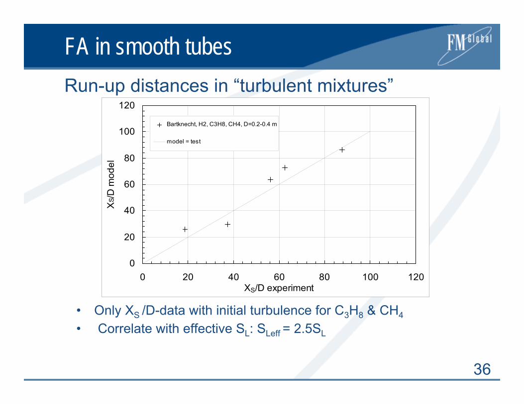
FA in smooth tubes
• Only XS /D-data with initial turbulence for C3H8 & CH4
• Correlate with effective SL: SLeff = 2.5SL
Run-up distances in “turbulent mixtures”
0
20
40
60
80
100
120
0 20 40 60 80 100 120XS/D experiment
XS /
D m
odel
Bartknecht, H2, C3H8, CH4, D=0.2-0.4 m
model = test
37
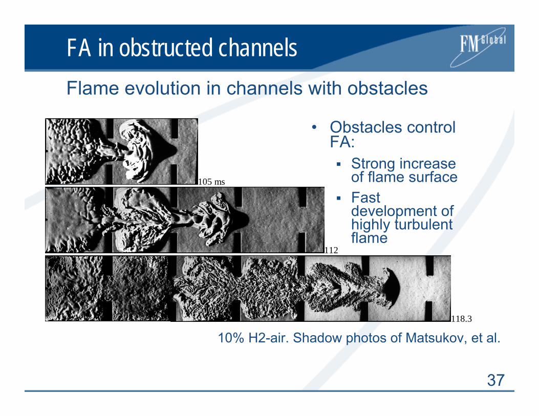
FA in obstructed channels
• Obstacles control FA:
Strong increase of flame surface Fast development of highly turbulent flame
Flame evolution in channels with obstacles
105 ms
112
118.3
10% H2-air. Shadow photos of Matsukov, et al.
38
FA in obstructed channels
• Flame surface increaseFlame speed relative to fixed observer:Vf = SLσ(Flame area)/(Flow cross-section) > 10SL
• Turbulence generated in the flow ahead of the flame affect the burning velocity ST
Increase of burning velocity ST/SL up to about 10 to 20• Total increase of flame speed relative to fixed
observer: Vf > 100SL
Two effects responsible for FA

39
FA in obstructed channels
Volume expansionFlow ahead of the flame
Turbulence + instabilitiesEnhanced combustion
More expansion
FA – Feedback mechanism

40
FA in obstructed channels
• Weak FA results in slow unstable turbulent flame regimes
• Strong FA leads to fast flames propagating with supersonic speed relative to a fixed observer
Weak and strong FA
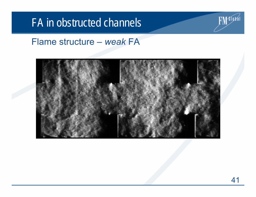
41
FA in obstructed channelsFlame structure – weak FA

42
FA in obstructed channelsFlame structure – strong FA

43
FA in obstructed channelsFlame speeds as a function of distance
H2-air BR=0.3
0 10 20 30 40 50 60 70x/D
0
400
800
1200
1600
2000
v, m
/s
520 mm10%H213%H2
80 mm10%H213%H2
174 mm10%H211%H212%H213%H215%H217.5%H2
H2-air0 10 20 30 40 50 60 70
x/D
0
400
800
1200
1600
v, m
/s 520 mm10%H211%H2
80 mm10%H211%H213%H2
174 mm10%H211%H215%H225%H245%H2
Quasi-detonations
Fast flames
Slow flames
H2 - airBR = 0.6
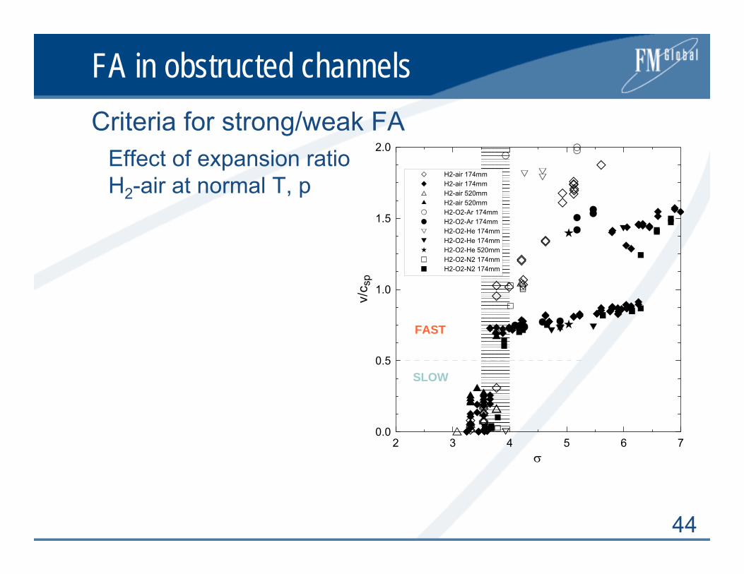
44
FA in obstructed channelsCriteria for strong/weak FA
Effect of expansion ratio H2-air at normal T, p
SLOW
FAST
2 3 4 5 6 7σ
0.0
0.5
1.0
1.5
2.0
v/c s
p
H2-air 174mmH2-air 174mmH2-air 520mmH2-air 520mmH2-O2-Ar 174mmH2-O2-Ar 174mmH2-O2-He 174mmH2-O2-He 174mmH2-O2-He 520mmH2-O2-N2 174mmH2-O2-N2 174mm

45
FA in obstructed channelsCriteria for strong/weak FAEffect of Markstein number
-4 -2 0 2 4 6 8 10 12Mab
1
2
3
4
5
6
σ
slow flameschoked flames and detonations
Increase of burning velocity with stretch
Decrease of burning velocity with stretch

46
FA in obstructed channelsCriteria for strong/weak FAEffect of Zeldovich number, β
2 3 4 5 6β
1
2
3
4
5
6
σ
Ma < 0slow flameschoked flames and detonations
3 4 5 6 7 8 9 10 11 12β
1
2
3
4
5
6
7
8
9
σ
Ma > 0slow flameschoked flames and detonations+- 8% deviation
H2 mixtures
CH - fuels
2
)(
b
uba
RTTTE −
=β

47
FA in obstructed channelsFlame – high turbulence (u’/SL)
Reactants Products

48
FA in obstructed channels
Quenching of the largest (=ALL) mixed eddies :
16
)12/(
1
2/122
=Γ−
+
−
κββσ β
nn
n
Lee
n = 1
1
3
5
7
9
11
6 9 12 15β
σ
Le = 0.3Le = 1Le = 2
Only mixture properties
Criteria for strong/weak FA
3 4 5 6 7 8 9 10 11 12β
1
2
3
4
5
6
7
8
9
σ
Ma > 0slow flameschoked flames and detonations+- 8% deviation
H2 mixtures
CH - fuels
Experiment Theory

49
FA in obstructed channels
• Flame shape is given by obstacle field
• Burning velocity ST is constant and equal to its max value ST ≈ 10SL
• XS is the distance where flame speed approaches Csp
• XS ∝ D for given mixture, BR, and initial T, p
Run-up distances Xs
X
R
Ω
Turbulent flame brush
ST
U
BRbBRa
cS
RX
sp
LS
⋅+−
≈−
11)1(10 σ
Data:SL: 0.1–1.5 m/sCsp: 640–1900 m/s
50
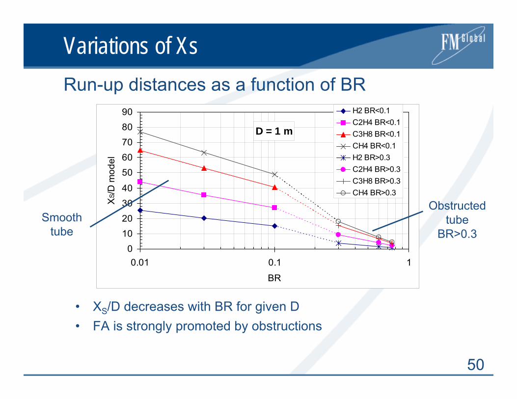
Variations of Xs
• XS/D decreases with BR for given D• FA is strongly promoted by obstructions
Run-up distances as a function of BR
D = 1 m
010203040
5060708090
0.01 0.1 1
BR
XS /
D m
odel
H2 BR<0.1C2H4 BR<0.1C3H8 BR<0.1CH4 BR<0.1H2 BR>0.3C2H4 BR>0.3C3H8 BR>0.3CH4 BR>0.3
Obstructed tube
BR>0.3Smooth
tube
51
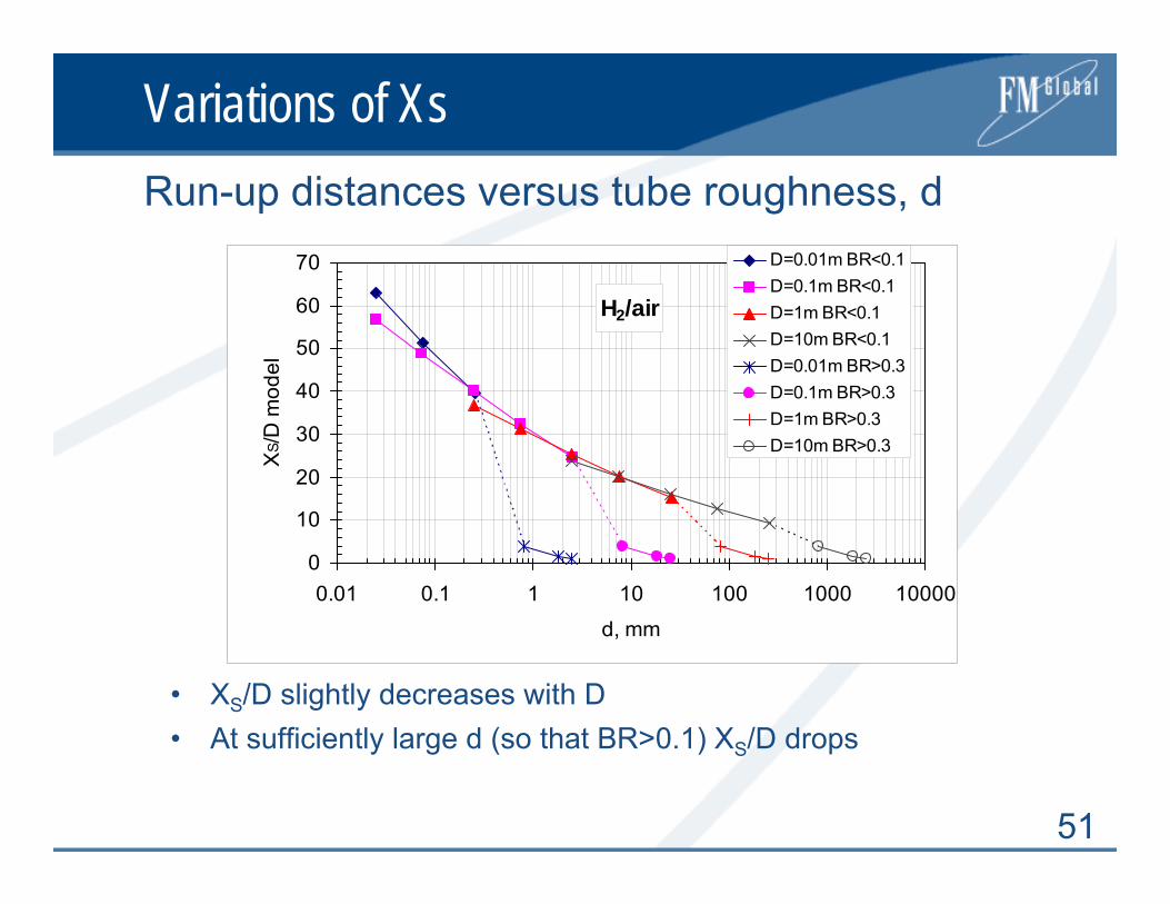
Variations of Xs
• XS/D slightly decreases with D• At sufficiently large d (so that BR>0.1) XS/D drops
Run-up distances versus tube roughness, d
H2/air
0
10
20
30
40
50
60
70
0.01 0.1 1 10 100 1000 10000
d, mm
XS /
D m
odel
D=0.01m BR<0.1D=0.1m BR<0.1D=1m BR<0.1D=10m BR<0.1D=0.01m BR>0.3D=0.1m BR>0.3D=1m BR>0.3D=10m BR>0.3
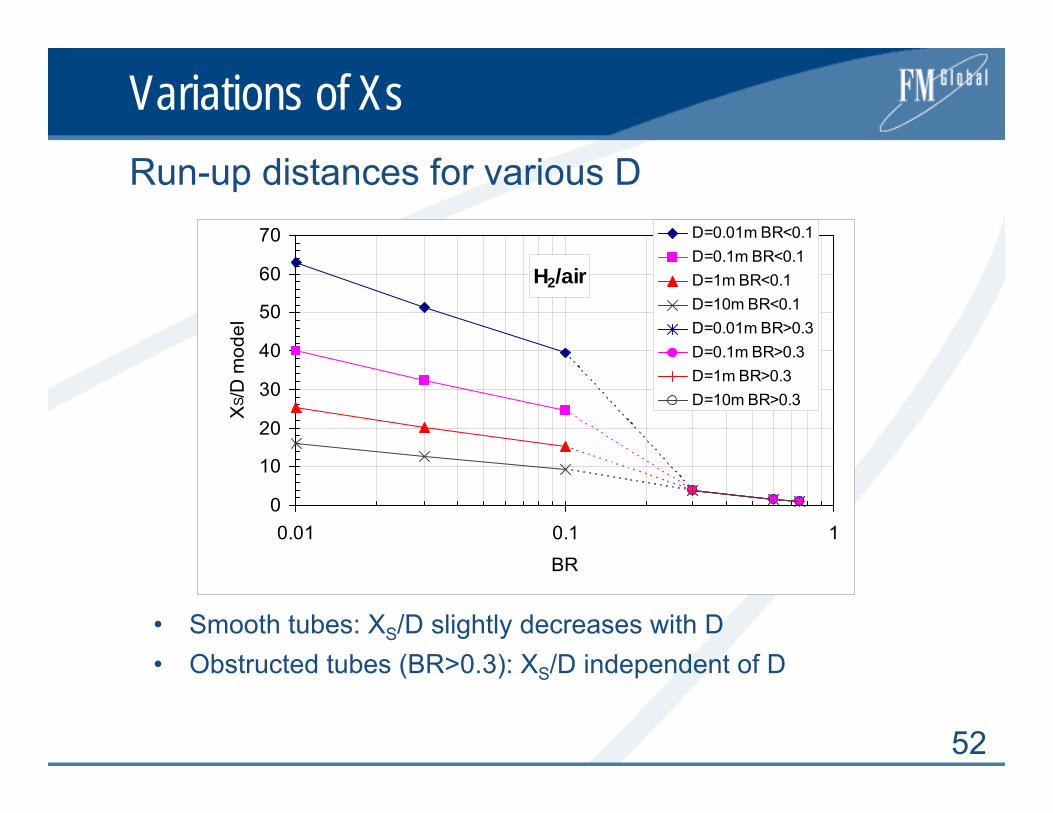
52
Variations of Xs
• Smooth tubes: XS/D slightly decreases with D• Obstructed tubes (BR>0.3): XS/D independent of D
Run-up distances for various D
H2/air
0
10
20
30
40
50
60
70
0.01 0.1 1
BR
XS /
D m
odel
D=0.01m BR<0.1D=0.1m BR<0.1D=1m BR<0.1D=10m BR<0.1D=0.01m BR>0.3D=0.1m BR>0.3D=1m BR>0.3D=10m BR>0.3
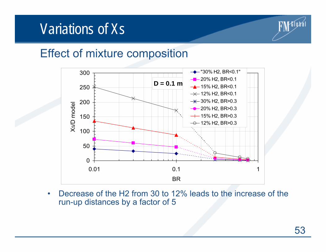
53
Variations of Xs
• Decrease of the H2 from 30 to 12% leads to the increase of the run-up distances by a factor of 5
Effect of mixture composition
D = 0.1 m
0
50
100
150
200
250
300
0.01 0.1 1
BR
XS /
D m
odel
"30% H2, BR<0.1"20% H2, BR<0.115% H2, BR<0.112% H2, BR<0.130% H2, BR>0.320% H2, BR>0.315% H2, BR>0.312% H2, BR>0.3
54
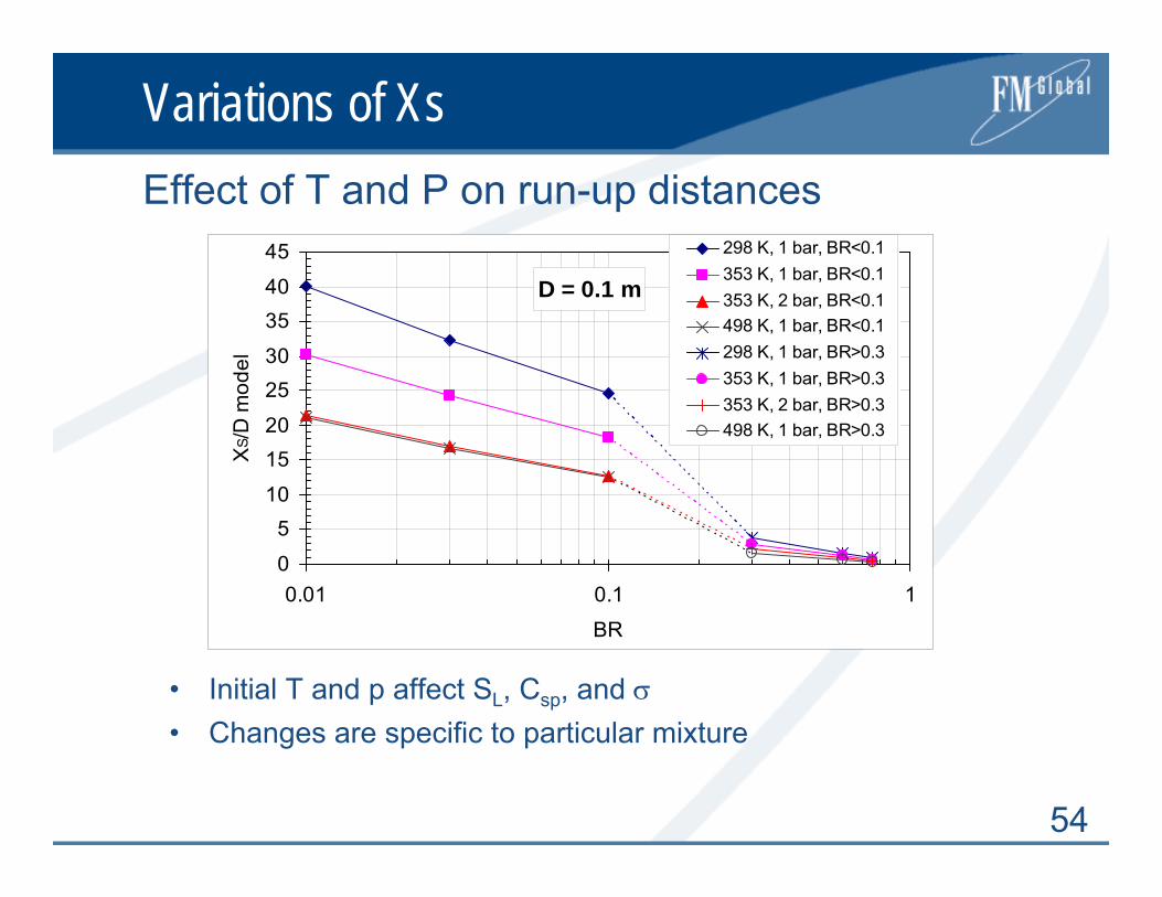
Variations of Xs
• Initial T and p affect SL, Csp, and σ• Changes are specific to particular mixture
Effect of T and P on run-up distances
D = 0.1 m
0
510
1520
2530
3540
45
0.01 0.1 1
BR
XS /
D m
odel
298 K, 1 bar, BR<0.1353 K, 1 bar, BR<0.1353 K, 2 bar, BR<0.1498 K, 1 bar, BR<0.1298 K, 1 bar, BR>0.3353 K, 1 bar, BR>0.3353 K, 2 bar, BR>0.3498 K, 1 bar, BR>0.3
55
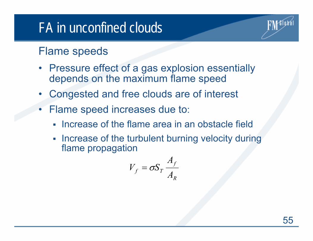
FA in unconfined clouds
• Pressure effect of a gas explosion essentially depends on the maximum flame speed
• Congested and free clouds are of interest• Flame speed increases due to:
Increase of the flame area in an obstacle field Increase of the turbulent burning velocity during flame propagation
Flame speeds
R
fTf AA
SV σ=
56
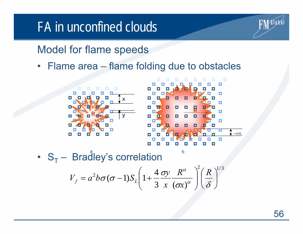
FA in unconfined cloudsModel for flame speeds• Flame area – flame folding due to obstacles
• ST – Bradley’s correlation 3/12
2
)(341)1( ⎟
⎠⎞
⎜⎝⎛
⎟⎟⎠
⎞⎜⎜⎝
⎛+−=
δσσσσ α
α RxR
xySbaV Lf
ba
∼σx
x
yRR
57
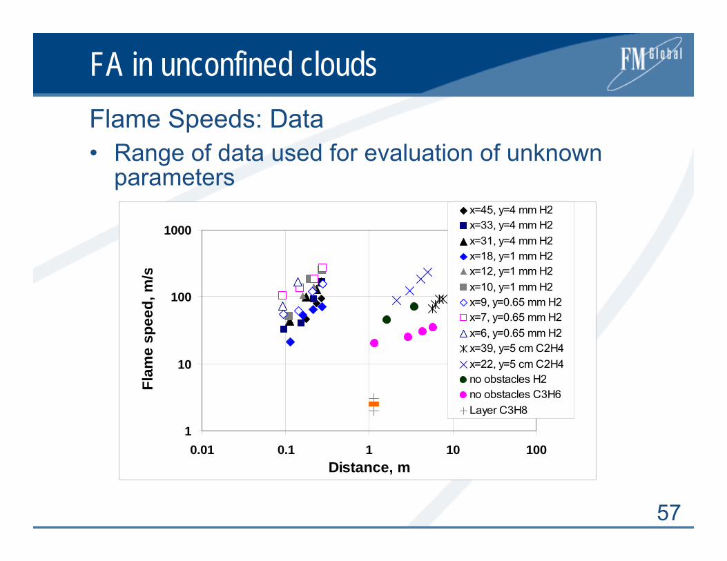
FA in unconfined cloudsFlame Speeds: Data• Range of data used for evaluation of unknown
parameters
1
10
100
1000
0.01 0.1 1 10 100Distance, m
Flam
e sp
eed,
m/s
x=45, y=4 mm H2x=33, y=4 mm H2x=31, y=4 mm H2x=18, y=1 mm H2x=12, y=1 mm H2x=10, y=1 mm H2x=9, y=0.65 mm H2x=7, y=0.65 mm H2x=6, y=0.65 mm H2x=39, y=5 cm C2H4x=22, y=5 cm C2H4no obstacles H2no obstacles C3H6Layer C3H8

58
FA in unconfined cloudsFlame Speeds: Model Calibration
1
10
100
1000
1 10 100 1000
Model flame speed, m/s
Exp.
flam
e sp
eed,
m/s
x=45, y=4 mm H2x=33, y=4 mm H2x=31, y=4 mm H2x=18, y=1 mm H2x=12, y=1 mm H2x=10, y=1 mm H2x=9, y=0.65 mm H2x=7, y=0.65 mm H2x=6, y=0.65 mm H2x=39, y=5 cm C2H4x=22, y=5 cm C2H4no obstacles H2no obstacles C3H6Layer C3H8 Layer C3H8Correlation
59
FA in unconfined clouds
• KI method (published in 1996)• Dimensionless P* and I* are functions of flame
speed, Vf , and R*
Link to blast parameters
),min( *2
*1
* PPP = ),min( *2
*1
* III =3*2*3/4**
1 )/(0033.0)/(062.0)/(34.0 RRRP ++=968.0**
1 )/(0353.0 RI =
))/(14.0/83.0(1 2**20
2*
2 RRcV
P f −−
=σ
σ
))/(0025.0)/(04.0/06.0(14.011 3*2**
00
*2 RRR
cV
cV
I ff −+⎟⎟⎠
⎞⎜⎜⎝
⎛ −−
−=
σσ
σσ
60
FA in unconfined cloudsP(R) for Various Flame Speeds
R* = R/(E/p0)1/3 – Sach’s dimensionless distance
0.01
0.10
1.00
10.00
0.10 1.00 10.00R/(E/P0)1/3
(P-P
o)/P
o
gas detonationTNT400 m/s200 m/s100 m/s

61
FA in unconfined clouds
• MERGE data – heavy congestion and IST data – unconfined H2/air (R=10m)
Validation - example
1
10
100
1000
1 10 100 1000Experimental P, kPa
Mod
el P
, kPa
CH4 MERGE
C3H8 MERGE
H2 ICT R=10munconfined

62
FA in unconfined clouds
• Stoichiometric mixtures and medium congestion y/x = 0.33 and x = 1 m
Flame speeds -examples
0
50
100
150
200
250
300
350
400
0 5 10 15Distance, m
Flam
e sp
eed,
m/s
H2
C2H4
C3H8
CH4

63
FA in unconfined clouds
• Variable concentration• Maximum concentration in the center, Cmax
• ‘Worst case’: maximum flame speed parameter <γ >=<σ(σ-1)SL>, averaged between UFL and LFL
• Properties of ‘worst case’:Flame speed is a fraction of max,Energy is a fraction of total chemical energy
Nonuniform cloud – ‘worst case’
LFL
Cmax
UFL
64
FA in unconfined clouds
• ‘Worst case’ clouds and medium congestion y/x = 0.33 and x = 1 m
Flame speeds - examples
0
50
100
150
200
250
300
350
400
1 10 100 1,000 10,000 100,000m, kg
Flam
e sp
eed,
m/s
H2
C2H4
C3H8
CH4
65
FA in unconfined clouds
• Total amount of H2 near the source is limited by buoyancy
• Maximum mass of H2 near release can be estimated as
Engineering correlation for release rate
Release time t* is time for buoyant displacement of cloud with CLFL=0.04 to be equal to size of cloud with C=CLFL.
High pressure releases of H2
vvrd PAKCm ρ2'=
5/35/1
2 2'*
−
⎟⎟⎠
⎞⎜⎜⎝
⎛ −⎟⎟⎠
⎞⎜⎜⎝
⎛=
gCmt
cloud
cloudair
HLFL ρρρ
ρξ

66
FA in unconfined clouds
• Estimate of maximum mass of H2 near the sourceHigh pressure releases of H2
0.001
0.01
0.1
1
10
100
1000
10000
0 200 400 600 800P, bar
m, k
g d = 1 mmd = 10 mmd = 100 mm
Release orifice d >10mm and high P are necessary for H2 clouds with m >10 kg and flame speeds > 80 – 100 m/s
67
DDT Phenomenology
• Following Lee & Moen (1980) and Shepherd & Lee (1991), DDT is divided into two phases:
1. Creation of conditions for the onset of detonationby FA, vorticity production, formation of jets, and mixing of products and reactants;
2. Actual formation of detonation itself or the onset of detonation
Phases of DDT process

68
Onset of detonations
• The key is to create conditions of localized explosion somewhere in the mixture
• Two types of detonation onset phenomena:1. Detonation initiation from shock reflection or focusing2. Onset of detonation caused by instabilities and
mixing processes• instabilities near the flame front • explosion of a quenched pocket of mixture • P and T fluctuations in the flow and boundary layer • …
Types of detonation onset phenomena

69
Onset of detonations
• Onset of detonation resulting from Mach reflection of lead shock of fast deflagration
Shock induced detonation initiation

70
Onset of detonations
• Onset of detonation triggered by interactions of pressure waves, flame, and boundary layer
Onset of detonation caused by instabilities
Boundary layer
Flame front
71
Onset of detonations
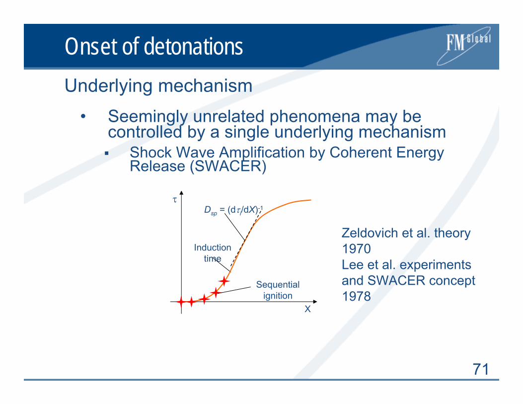
• Seemingly unrelated phenomena may be controlled by a single underlying mechanism
Shock Wave Amplification by Coherent Energy Release (SWACER)
Underlying mechanism
τ
X
Induction time
Sequential ignition
Dsp = (dτi/dX)-1
Zeldovich et al. theory 1970Lee et al. experiments and SWACER concept 1978

72
Onset of Detonations
1. Conditions for localized autoignition should be created
2. Gradient of induction time should provide coupling of chemistry and gasdynamics to create explosion wave
3. This wave should survive propagating thorough gradient of induction time and adjust itself to the chemical length scale of ambient mixture
Requirementst
X
Reaction length
Spontaneous flame Shock
wave
Compression wave
Reaction front
Sensitized mixture
Unperturbed mixture
• 1 and 2 require sufficiently high flame speed (~csp)• 3 requires sufficiently large size of sensitized
region (~10λ)

73
Onset of D in smooth tubes
• Flame should reach a speed of about cspSee FA correlations
• Min. scale requirement related to the tube sizeTube diameter should be greater than the detonation cell width D > λ (Peraldi et al.)Kogarko & Zeldovich, and Lindstedt et al., argued that D > λ/π should be usedMost conservative D > λ/π preferable for applications
Necessary conditions

74
Onset of D in smooth tubes
• Stoichiometric H2-air, roughness=0.1mm, λ=10mmDDT possible with D=10 cm at X > Xs ≈ 4.5 mOnset of D impossible with D < 3mm (D > λ/π)
Example
H2/air
0
10
20
30
40
50
60
70
0.01 0.1 1 10 100 1000 10000
d, mm
XS /
D m
odel
D=0.01m BR<0.1D=0.1m BR<0.1D=1m BR<0.1D=10m BR<0.1D=0.01m BR>0.3D=0.1m BR>0.3D=1m BR>0.3D=10m BR>0.3

75
Onset of D in channels with obstacles
• Flame should reach a speed of about csp
• Scale requirement related to tube sizeSize of unobstructed passage d/λ > 1d/λ increases with decrease of obstacle spacing and with increase of BR Variations of critical d/λ can be quite large, from 0.8 to 5.1 for BR from 0.3 to 0.6
Necessary conditions: d/λ

76
Onset of D in channels with obstacles
• Scale requirement related to possible macroscopic size of the sensitized mixture or characteristic mixture size L
For a channel or room with obstacles the characteristic size L is given by
Necessary conditions: L/λ
HdSHL/1
2/)(−+
=
L
dSH
77
Onset of D in channels with obstacles
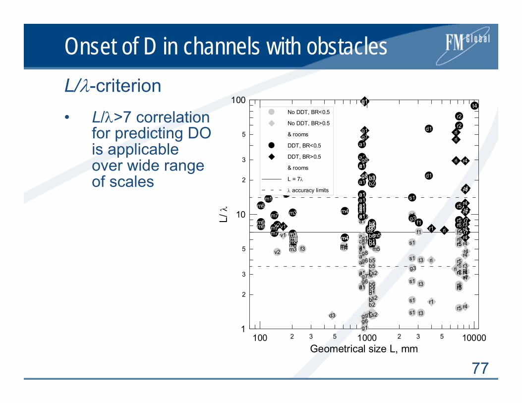
• L/λ>7 correlation for predicting DO is applicable over wide range of scales
L/λ-criterion
2 3 5 2 3 5100 1000 10000Geometrical size L, mm
2
3
5
2
3
5
1
10
100
L/ λ
d2
d2g3
s1
s1
s1
s1
s1
s1
t3
t3
t3
a1
a1a1a1
a1
a1
a1
a1
a1
a1a1
a1
a1
a1
a1
a1a1
f1
f3
r2
r2
r5
r5
r5
r5
r5r5
r5
r5r5
r6
r6
v2
b1b1
b1
b2
b2
b2b2
b4b4
b4
b4
b4
b5b5
b6b6
b6
b6
m3m3 m4m4m4 m5
d3
g1
g1g6
g6
g6
g7
g7
g7
g8
g8
g9
r1s2
s2
s2
r3
r4r4r4r4
r4
r4
r4r4
r7
v1
riri
d1
d1
t4
d2d2
g3
s1
a1a1
a1
a1
a1
a1
a1
a1
a1
a1
a1
a1a1a1a1
f1
f3
r2r2
r5
r5
r6v2
b1b1
b2
b2
b3b3
b4
b5b5b6b6
m3
m3m3
m4
m4m4 m5
m1m2
m6
m6m6
m7
m7m7
m8m8m8
g1g1
g1
g7
g7
g8
g8
r1r3r4
r4
r4r4
r4
r4
r4
r4
r7
r7v1
riri
ri
ri
No DDT, BR<0.5
No DDT, BR>0.5
& rooms
DDT, BR<0.5
DDT, BR>0.5
& rooms
L = 7λ
λ accuracy limits

78
Onset of D in channels with obstacles
• Stoichiometric H2-air, λ=10 mmDDT possible with D=10 cm, BR=0.3 at X > Xs ≈ 0.4mOnset of D impossible with D = 1cm, BR = 0.6 (L<7λ)
Example
H2/air
0
10
20
30
40
50
60
70
0.01 0.1 1
BR
XS /
D m
odel
D=0.01m BR<0.1D=0.1m BR<0.1D=1m BR<0.1D=10m BR<0.1D=0.01m BR>0.3D=0.1m BR>0.3D=1m BR>0.3D=10m BR>0.3
79
Onset of D in unconfined mixtures
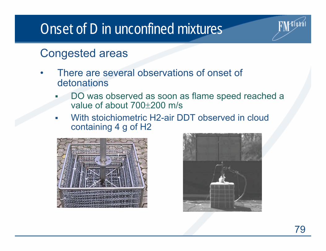
• There are several observations of onset of detonations
DO was observed as soon as flame speed reached a value of about 700±200 m/sWith stoichiometric H2-air DDT observed in cloud containing 4 g of H2
Congested areas

80
Onset of D in unconfined mixtures
• No convincing observations of DO under truly unconfined conditions
Turbulent jet initiationSensitive mixtures in envelopes • Shchelkin 22% C2H2 +78%O2 in 420mm rubber
sphere – DO at 50 mm• Gostintsev et al. no transition, same mixture,
rubber sphere 600mm
No obstructions
81
Onset of D in unconfined mixtures
• Shchelkin 22% C2H2 +78%O2 in 420mm rubber sphere – DO at 50 mm
Nearly unconfined DDT
82
Onset of D in unconfined mixtures
• Critical conditions: Djet ≥ (14-24)λ
Turbulent jet initiation
Mixture
Hot jet
215 m3Detonation of H2-air initiated by hot turbulent jet of combustion products

83
Summary
1. In order for FA to be strong, a sufficiently large expansion ratio σ = ρu/ρb > σ* is necessary
• σ* depends on the mixture composition and initial T and P
2. Even if σ > σ*, tube diameter should be > 102 laminar flame thickness (δ)
3. If strong FA is possible (σ > σ*, D > 102δ), a sufficiently large run-up distance Xs is necessary for actual development of supersonic combustion regimes
Evaluation of potential for FA and DDT
Vflame = f(R) ≤ Csp

84
Summary
4. If supersonic regime is developed, detonation may only occur if the size of a duct or mixture volume is sufficiently large compared to λ
D ≥ λ/π, where D is the internal diameter of a smooth tube d ≥ λ, where d is the transverse dimension of the unobstructed passage in a channel with obstaclesL ≥ 7λ, where L is a more general characteristic size defined for rooms or channels Djet ≥ (14-24)λ , where Djet refers to the exit diameter of the jet
Detonation is possible
85
Concluding Remarks 1
• There are many spatial and temporal physical scales involved in FA and detonation
• These scales are given by chemistry, turbulence, and confinement
• The interplay of these scales control major features and thresholds,
Onset of instabilities & flame structure, Onset & structure of detonations
• Wide range of the scales makes it difficult to resolve all the phenomena from first principles
• However, it is the comparison of scales that give us a way to approach practical problems

86
Concluding Remarks 2
• Critical conditions for strong FA and the onset of detonation are formulated as necessary criteria
• Uncertainties are related to Critical values of mixture expansion ratio, Detonation cell size dataLaminar burning velocity and flame thicknessEffect of the Lewis number Issues in respect to changes of thermodynamic state of unburned mixture during FA, which can change the critical conditions for DDT
• All should be taken into account in practical applications

87
Questions?

88
Deflagrations
• Laminar burning velocity
• Zeldovich number
• Flame thickness
Laminar flames – one step reaction
rnbn
nLTLeSτβ
χσ 11
)(21++Γ=
2
)(
b
uba
RTTTE −
=β
L
b
Lu
bb
ST
ST
σχ
ρχρδ )()(
==LS
νδ =
89
Deflagrations
• Markstein suggested that normal velocity of a curved flame, Sn, may be expressed as in terms of flame stretch, α = 2Sn/Rf
Instabilities and flame stretch
αδα
LL
b
L
n
SMa
SL
SS
==−1
δ/bLMa =
90
Deflagrations
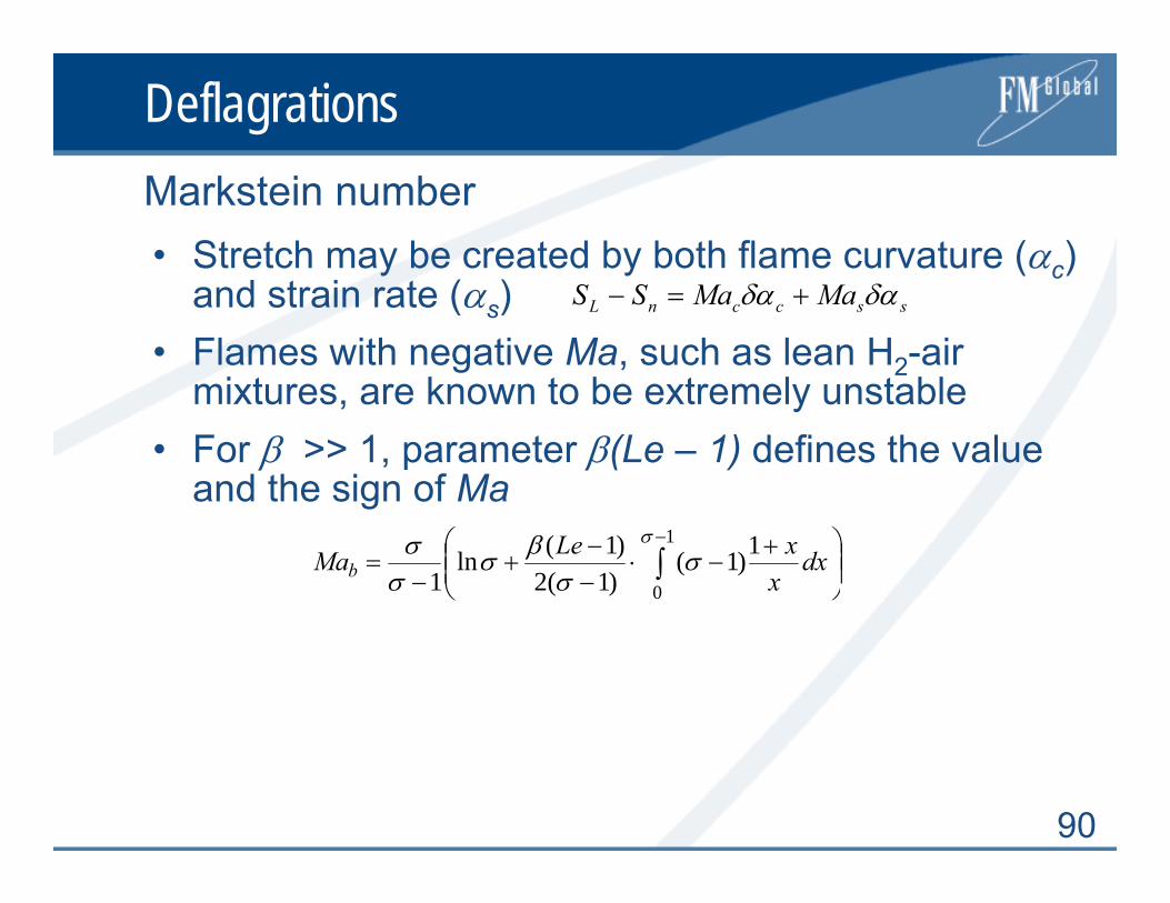
• Stretch may be created by both flame curvature (αc) and strain rate (αs)
• Flames with negative Ma, such as lean H2-air mixtures, are known to be extremely unstable
• For β >> 1, parameter β(Le – 1) defines the value and the sign of Ma
Markstein number
⎟⎟⎠
⎞⎜⎜⎝
⎛ +−⋅
−−
+−
= ∫−1
0
1)1()1(2)1(ln
1
σσ
σβσ
σσ dx
xxLeMab
ssccnL MaMaSS δαδα +=−

91
DeflagrationsTurbulent combustion regimes
Borghi diagram
PLIF images of flame structure for various regimes – U-Munich
u'/SL
1 10 100 1000
1
10
100
LT/δ
LT = δ
lK = δ
Laminar flamelets
Thick flames
Well stirred reactor
FA in given geometry

92
Detonations
• 1D model
Chapman Jouguet Detonation
QUu3
P1ρ1
P3ρ3
Shock waveReaction zone
P/P1
ρ1/ρ
1
1
J
V
P1
C
EquilibriumHugoniot
Rayleigh Line2
ShockHugoniot
13 )1(2 aQDCJ >>+≅ γ


