TOYOTA FJ CRUISER 2007 - TRAILER WIRE HARNESS Preparation
Page 1 of 12 pages Issue: B 02/27/06 LA 990009-1802
Part Number: 08921-35870 NOTE: Part number of this accessory may not be the same as the part number shown.
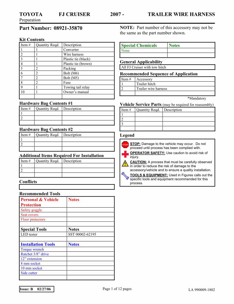
Kit Contents Item # Quantity Reqd. Description 1 1 Converter 2 1 Wire harness 3 1 Plastic tie (black) 4 1 Plastic tie (brown) 5 2 Packing 6 2 Bolt (M6) 7 2 Bolt (M5) 8 2 Fuse 9 1 Towing tail relay 10 1 Owner’s manual
Hardware Bag Contents #1 Item # Quantity Reqd. Description 1 2
Hardware Bag Contents #2 Item # Quantity Reqd. Description 1 2
Additional Items Required For Installation Item # Quantity Reqd. Description 1 2
Conflicts
Recommended Tools Personal & Vehicle Protection
Notes
Safety goggle Seat covers Floor protectors Special Tools Notes LED tester SST 00002-62195 Installation Tools Notes Torque wrench Ratchet 3/8” drive 12” extension 8 mm socket 10 mm socket Side cutter
Special Chemicals Notes None
General Applicability All FJ Cruiser with tow hitch
Recommended Sequence of Application Item # Accessory 1 Trailer hitch 2 Trailer wire harness
*Mandatory
Vehicle Service Parts (may be required for reassembly) Item # Quantity Reqd. Description 1 2 3
Legend
STOP: Damage to the vehicle may occur. Do not proceed until process has been complied with. OPERATOR SAFETY: Use caution to avoid risk of injury. CAUTION: A process that must be carefully observed in order to reduce the risk of damage to the accessory/vehicle and to ensure a quality installation.TOOLS & EQUIPMENT: Used in Figures calls out the specific tools and equipment recommended for this process.

TOYOTA FJ CRUISER 2007 - TRAILER WIRE HARNESS Procedure
Page 2 of 12 pages Issue: B 02/27/06 LA 990009-1802
Care must be taken when installing this accessory to ensure damage does not occur to the vehicle. The installation of this accessory should follow approved guidelines to ensure a quality installation. These guidelines can be found in the "Accessory Installation Practices" document. This document covers such items as:-
• Vehicle Protection (use of covers and blankets, cleaning chemicals, etc.). • Safety (eye protection, rechecking torque procedure, etc.). • Vehicle Disassembly/Reassembly (panel removal, part storage, etc.). • Electrical Component Disassembly/Reassembly (battery disconnection, connector removal, etc.).
Please see your Toyota dealer for a copy of this document.
1. Supplemental Restraint System SRS
(a) Failure to carry out procedures listed below could result in possible deployment of airbag, personal injury, or unnecessary repairs to SRS.
(b) Turn the key switch to the LOCK position. (Fig. 1)
(c) Remove the key from the ignition switch.
(d) Never use a voltmeter to trouble shoot any of the harnesses or connector to the SRS. Accidentally probing the connectors to the SRS can lead to deployment of the airbag. (Fig. 2)
(e) SRS wire harness loom/cover is bright yellow in color.
2. Wiring Precautions
(a) DO NOT pull on vehicle wires and/or wire harness. To uncouple electrical connectors, pull only on the connector itself. (Fig. 3)
(b) Use nylon ties and adhesive foam strips to secure the vehicle harness and the trailer wire harness.
(c) Ensure all wires are properly insulated from ground.
Fig.1
Fig.2
Fig.3
INCORRECT CORRECT

TOYOTA FJ CRUISER 2007 - TRAILER WIRE HARNESS Procedure
Page 3 of 12 pages Issue: B 02/27/06 LA 990009-1802
(d) When installing the trailer wire harness make sure it is not cut or perforated by any sharp metal objects.
3. General Practices and Procedures
(a) Before starting installation, refer to the supplemental restraint system procedures in Section 1.
(b) Take care not to scratch any part of the vehicle. Bind the tips of tools (clip remover, slot screw driver, etc.) with vinyl tape to prevent damage to any part of the car, or use a nylon removal tool (resin based prying tool). (Fig. 4)
(c) Use a small parts container to store removed bolts and tapping screws so that they can be reassembled correctly.
(d) Ensure seat/floor protectors are in position.
(e) After fastening plastic ties, clip away all the excess of the ties using diagonal pliers. (Fig. 5)
Fig.4
Nipper Cut away the excess part of all plastic ties, after fastening
Fig.5

TOYOTA FJ CRUISER 2007 - TRAILER WIRE HARNESS Procedure
Page 4 of 12 pages Issue: B 02/27/06 LA 990009-1802
Fig. 6
CONVERTER
WIRE HARNESS
TOYOTA FJ CRUISER 2007 - TRAILER WIRE HARNESS Procedure
Page 5 of 12 pages Issue: B 02/27/06 LA 990009-1802
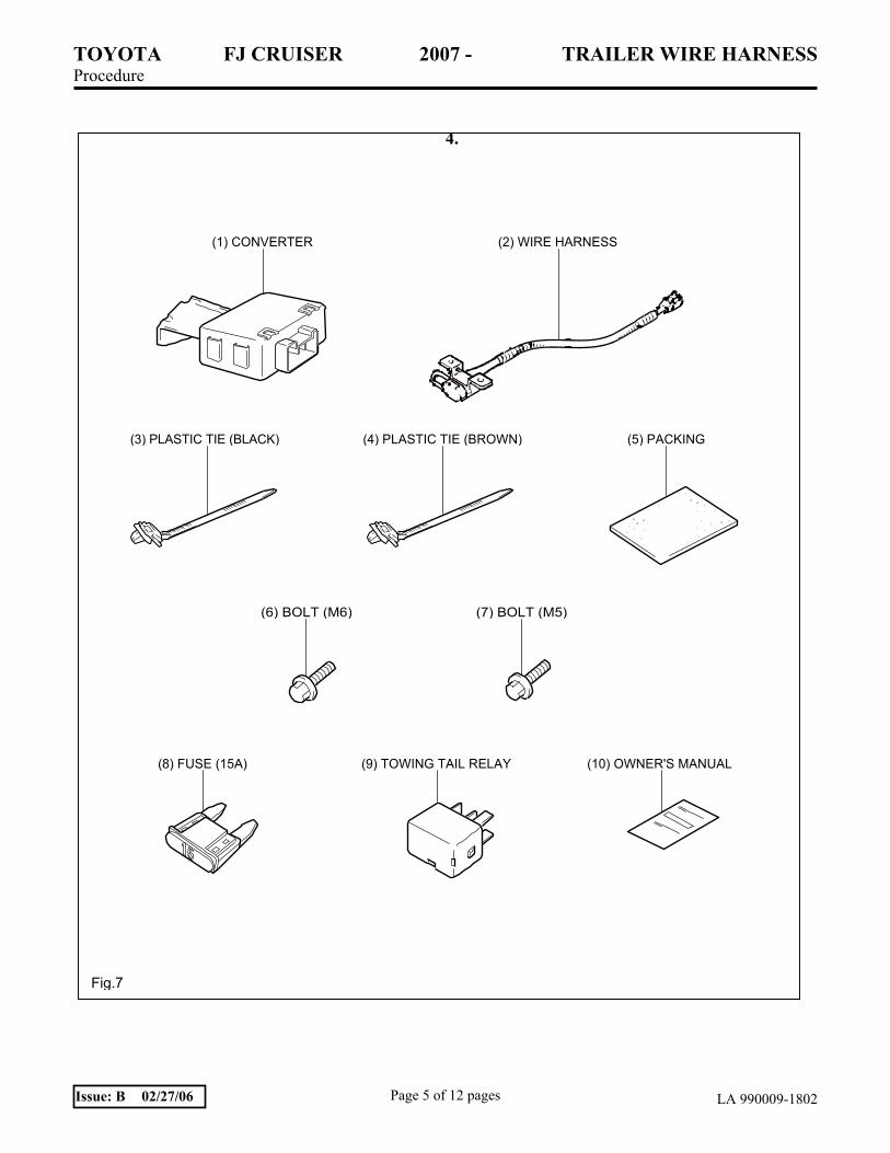
4.
(1) CONVERTER (2) WIRE HARNESS
(3) PLASTIC TIE (BLACK) (4) PLASTIC TIE (BROWN) (5) PACKING
(6) BOLT (M6) (7) BOLT (M5)
(8) FUSE (15A) (9) TOWING TAIL RELAY (10) OWNER'S MANUAL
Fig.7

TOYOTA FJ CRUISER 2007 - TRAILER WIRE HARNESS Procedure
Page 6 of 12 pages Issue: B 02/27/06 LA 990009-1802
1. Parts Removal.
(a) Relay box cover.
(1) Remove relay box cover. (Fig. 1-1)
2. Converter Installation.
(a) Install the packing to the converter as shown. (Fig. 2-1)
(b) M/T vehicle only (c) – (h).
(c) Remove the tape that holds the vehicle connector. (Fig. 2-2)
(d) Install the packing to the vehicle harness as shown. (Fig. 2-3)
(e) Wrap the packing around the vehicle harness starting at the base of where the vehicle harness branches off.
M/T ONLY
VEHICLE HARNESS
FRONT PACKING
Fig.2-3 BRANCH OFF
RELAY BOX COVER HOOK
Fig.1-1 HOOKS
3)
2)
CONVERTER
1) MATCH LINE OF PACKING
CONVERTER
PACKINGPACKING
Fig.2-1 PACKING CONVERTER
M/T ONLY FRONT VIEW:FRONT
TAPE
Fig.2-2 VIEW:A VEHICLE CONNECTOR (9P)

TOYOTA FJ CRUISER 2007 - TRAILER WIRE HARNESS Procedure
Page 7 of 12 pages Issue: B 02/27/06 LA 990009-1802
(f) Put the converter bracket hook into the vehicle hole and attach it with the bolt (M6) included in the kit. (Fig. 2-4)
(g) Tighten the bolt with 8 N-m (71 lbf-in) of torque. (Fig. 2-4)
(h) Connect the vehicle harness (9P) to the converter (9P). (Fig. 2-4)
(i) A/T vehicle only (j) – (o)
(j) Remove the tape that holds the vehicle connector (9P). (Fig. 2-5)
(k) Install the packing to the vehicle harness as shown. (Fig. 2-6)
(l) Wrap the packing around the vehicle harness starting at the base of where the vehicle harness branches off. (Fig. 2-6)
(m) Put the converter bracket hook into the vehicle hole and fix it with the bolt (M6) included in the kit. (Fig. 2-7)
(n) Tighten the bolt with 8 N-m (71 lbf-in) of torque. (Fig. 2-7)
(o) Connect the vehicle harness (9P) to the converter (9P). (Fig. 2-7)
A/T ONLY FRONT VEHICLE CONNECTOR(9P)
VIEW:
Fig.2-5 TAPE
VIEW:A FRONT
A/T ONLY
VEHICLE HARNESS
PACKING
Fig.2-6
FRONT BRANCH OFF
M/T ONLY 10mm Socket, Torque Wrench
CONVERTER
VEHICLE CONNECTOR (9P)
VEHICLE HOLE
BOLT (M6)
FRONT
Fig.2-4 (INCLUDED IN
A/T ONLY
CONVERTER VEHICLE
10mm Socket, Torque WrenchVEHICLE HOLE
FRONT
BOLT (M6) (INCLUDED IN KIT)CONNECTOR (9P)
Fig.2-7

TOYOTA FJ CRUISER 2007 - TRAILER WIRE HARNESS Procedure
Page 8 of 12 pages Issue: B 02/27/06 LA 990009-1802
3. Wire Harness Installation.
(a) Cap.
(1) Remove the cap from vehicle harness. (Fig. 3-1)
(b) Connect the wire harness (4P) to the vehicle harness (4P). (Fig. 3-2)
(c) Fastening flat (4P) connector of wire harness.
(1) Fasten flat (4P) connector of wire harness with two (2) bolts (M5) included in kit. (Fig. 3-3)
(2) Tighten the bolt with 3.9 N-m (36 lbf-in) of torque.
(d) Secure the wire harness as shown to the bracket with the plastic tie (black). (Fig. 3-4)
(e) Be sure to use a black plastic tie. Do not use a brown one. (Fig. 3-4)
(f) Secure the wire harness as shown to the vehicle hole with the plastic tie (brown).
UNDER THE COMPARTMENTFRONT
CAP(DISCARD)
Fig.3-1 REAR BUMPER
UNDER THE COMPARTMENT FRONT
WIRE HARNESS (4P)
Fig.3-2 REAR BUMPER VEHICLE HARNESS (4P)
UNDER THE COMPARTMENT
8mm Socket, Torque Wrench
WIRE HARNESS
VIEW:A
FRONT
Fig.3-3 VIEW:A REAR BUMPER BOLTS (M5)(INCLUDED IN KIT)
UNDER THE COMPARTMENT
WIRE HARNESS
FRONT
BRACKET
PLASTIC TIE(BLACK)
Fig.3-4 REAR BUMPER
BRACKET HOLE

TOYOTA FJ CRUISER 2007 - TRAILER WIRE HARNESS Procedure
Page 9 of 12 pages Issue: B 02/27/06 LA 990009-1802
(g) Be sure to use a brown plastic tie. Do not use a black one. (Fig. 3-5)
(h) Be sure not to have any slack in vehicle harness when securing it with a plastic tie (brown). (Fig. 3-5)
4. Installing the Fuse and Relay.
(a) Install the towing tail relay (included in kit) to the position as shown. (Fig. 4-1)
(b) Pay attention to the following points when handling the towing relay:
(1) Avoid striking the towing tail relay. Never use a relay that has been dropped. Do not strike or use undue force when installing the towing tail relay to the vehicle. It may damage the vehicle.
(2) Do not touch the terminal directly with fingers.
NOTE: Contamination of any oils or grease may impair the operation of the towing tail relay. (This includes oils from hands).
(3) Do not apply lubrication oil or grease to the terminal.
NOTE: Terminal generates heat and it may lead to internal overheating and failure.
(c) Install two (2) fuses (15A) (included in kit) to the position as shown. (Figs. 4-2 and 4-3)
5. Reinstallation.
(a) After functional verification, reinstall all temporarily removed parts.
TOWING TAIL RELAY (INCLUDED IN KIT) Fig.4-1 RELAY BOX
TOWING TAIL FUSE
Fig.4-2
(INCLUDED IN KIT)RELAY BOX
UNDER THE COMPARTMENT
WIRE HARNESS
Fig.3-5 REAR BUMPER
FRONT VEHICLE HOLE PLASTIC TIE (BROWN)
TOWING FUSE (15A) (INCLUDED IN KIT)
Fig.4-3 RELAY BOX

TOYOTA FJ CRUISER 2007 - TRAILER WIRE HARNESS Checklist - these points MUST be checked to ensure a quality installation.
Check: Look For:
Page 10 of 12 pages Issue: B 02/27/06 LA 990009-1802
Accessory Function Checks
Faults in the wiring harness installation
Converter mounting
Wire harness
Plastic tie locations
Vehicle Function Checks
Removed parts
With the Special Service Tool (SST) (Part Number 00002-62195) attached to the trailer sub wire harness plug and with the engine running, perform the following steps: Caution: Be sure the exhaust gas is completely ventilated. Caution: Be sure the vehicle is in “Park” and that the parking brake is applied.
Turn on headlamps
Turn on left turn signal
Turn on right turn signal
Apply foot brake
Turn on left turn signal and apply foot
brake
Correct routing of the wire harness
Pushing or pulling of the converter by any
outside force
Pinching of the wire harness
Positioning of the plastic tie locations
Scratches or other damage
Marker and tail lights on both SST and
vehicle are lit
Left turn lights on both SST and vehicle are
flashing
Right turn lights on both SST and vehicle
are flashing
Stop lights on both SST and vehicle are lit
Left turn lights are flashing and right stop
lights are lit on both SST and vehicle.

TOYOTA FJ CRUISER 2007 - TRAILER WIRE HARNESS Checklist - these points MUST be checked to ensure a quality installation.
Check: Look For:
Page 11 of 12 pages Issue: B 02/27/06 LA 990009-1802
Turn on right turn signal and apply foot
brake
Turn on hazard lights switch
With hazard lights switch on, apply the foot
brake
Turn off the hazard light switch, apply the
foot brake
The following checks are to be performed with the ignition switch off and the engine stopped.
Turn on headlamps
Apply foot brake
Turn on left turn signal
Turn on right turn signal
Turn on left turn signal and apply foot
brake
Turn on right turn signal and apply foot
brake
With hazard lights switch on, apply the foot
brake
Turn off the hazard light switch, apply foot
brake
Right turn lights are flashing and left stop
lights are lit on both SST and vehicle
All turn signal lights are flashing on both
SST and vehicle
Both stop lights on the vehicle are lit, both
turn/stop lights on the SST and the turn
lights on the vehicle are flashing
Both turn/stop lights on the SST and the
stop lights on the vehicle are lit.
Marker and tail lights on both SST and
vehicle are lit
Stop lights on both SST and vehicle are lit
Left turn lights are not lit on both SST and
vehicle
Right turn lights are not lit on both SST and
vehicle
Both stop lights are lit and not flashing on
both SST and vehicle
Both stop lights are lit and not flashing on
both SST and vehicle
All turn signal lights are flashing on both
SST and vehicle
Both stop lights on the vehicle and the
turn/stop lights on the SST are lit, but not
flashing

TOYOTA FJ CRUISER 2007 - TRAILER WIRE HARNESS Wiring Diagram
Page 12 of 12 pages Issue: B 02/27/06 LA 990009-1802
WIRING DIAGRAM
12V TOWING
FUSE TOWING TAIL 15A
TAIL RELA
STOP LIGHT SWITCH
(3)
FUSE TOWING 15A
CONVERTER
TAIL RELAY
TAIL
FLASHER 1 8 3 9
+B
STOP INPUT
TURN(RIGHT)INPUT
TURN(LEFT)INPUT
TAIL STOP
VEHICLE LAMP
3 2 2 3
4 STOP/TURN(LEFT) OUTPUT
4 1 2 STOP/TURN(RIGHT) OUTPUT
1 4 6GND
(1)
STOP/
TURN TAIL STOP/ TURN
WIRE HARNESS
LEFT SIDE RIGHT SIDE
TRAILER LAMP
CONNECTOR
(1) (2)
1 2 1 2 31 2 3 4 3 4 4 5 6 7 8
Fig.8


