
WEB www.sariak.com EMAIL info sariak.com@
Oil, Gas, petrochemical and Refinery plants
Steel, Copper and Cement industries
Chemical Plants
Power Plants & Substations
Commercial enterprises
Fire Alarm & Gas Fire Alarm & Gas
Detection SystemDetection System

PHONE
FAX
WEB
0098 21 8873 38 12-3
0098 21 8876 44 55
www.sariak.com
Product Showcase Honeywell Analytics and BW Technologies by Honeywell are able to offer a wide range of gas detection
solutionsdesigned to meet the needs of all applications and industries. In this feature we showcase the full
range of gas detection products supplied by Honeywell.
Fixed Gas Detection (Flammable and Toxic)
Our comprehensive range of flammable, toxic and
Oxygen gas detectors have options suited to all
industries and applications. XNX Universal
Transmitter
A universal transmitter
compatible with all
Honeywell Analytics
gas sensor
technologies
2-wire loop powered toxic and Oxygen gas
detector for use in potentially explosive
atmospheres
A flammable gas transmitter for use with
remotely mounted flammable gas
sensors
Series3000MkII SensepointXCDRFD
Flammable, toxic and Oxygen transmitter and sensor with tri-
color display for viewing status from a
distance
World renowned open path IR detector with
200m dynamic
monitoring range
High performance flammable and toxic
detector with choice of communications
platforms
Market leading point IR detector with 100
gases available
Low cost range of flammable, toxic and Oxygen gas detectors
Low cost range of flammable, toxic and Oxygen gas detectors
with integral gas concentration display
Low-cost ATEX certified flammable,
toxic and Oxygen gas
detectors
SensepointXCD SearchlineExcel Apex SearchpointOptimaPlus
SignalpointRange SignalpointPro SensepointRange
Vertex M
Cost effective,8-24 point toxic gas monitoring with
physical evidence of a leak
VertexTM
Flexible device providing
continuous monitoring of up to
72 points
Midas®
Sensitive detection using smart sensor
cartridges and Power over
Ethernet (PoE)
Chemcassette®
Calibration free toxic gas detection
with physical
evidence of a leak
Satellite XT
Small and compact toxic gas detection with a wide range of
sensors
Sat-Ex
Comprehensive monitoring of corrosive, combustible
and toxic gases in potentially explosive
atmospheres
SPM Single Point Monitor
A fast response device detecting in the ppb range with physical evidence of a leak
ACM 100FT-IR
Versatile and sensitive detection of up to40 points with many gases
available
ChemKeyTMTLD
Portable, flexible toxic gas detection
with physical
evidence of a leak
CM4
Low cost, continuous monitoring of toxic
gases on 4 points with minimal main tenance
requirement
SatellitePGD
Small and portable gas detection ideal for emergency response
and laboratory work
Fixed Gas Detection (Toxic)
When it comes to laboratory work or hi-tech industries such as
pharmaceutical or semi-conductor, the most sensitive
instrumentation is required. We offer a diverse selection of robust
solutions capable of detecting low levels (ppb) of toxic gases.

PHONE
FAX
WEB
0098 21 8873 38 12-3
0098 21 8876 44 55
www.sariak.com
Product showcase Benefits of using XNX Universal Transmitter
Reduce the ongoing cost of gas detection with a single transmitter interface solution to all your onsite gas detection
XNX Universal Transmitter from Honeywell Analytics is a feature rich transmitter that not only simplifies gas monitoring but also drives down the cost of gas detection in terms of installation and a reduced ongoing cost of ownership.
Its design means that XNX Universal Transmitter can be used with any of Honeywell Analytics’ range of gas sensor technologies including Searchline Excel, Searchpoint Optima Plus, Sensepoint (HT and PPM) and Model 705. This means that sites using a variety of sensing principles for the detection of flammables, toxic or Oxygen gas hazards can have one common interface, helping to reduce the need for training and spares.

PHONE
FAX
WEB
0098 21 8873 38 12-3
0098 21 8876 44 55
www.sariak.com
Cost effective toxic gas detection for challenging environments and hard to reach applicationsSensepoint XCD RTD from Honeywell Analytics combines cost effective performance and maintenance with ease of use and the exibility to meet the demands of a wide range of varied environments requiring the detection of toxic gases.The device has been designed for use with Honeywell Analytics’ range of Sensepoint toxic and Oxygen sensors, providing the ideal solution for a wide variety of applications. The remote sensor mount aspect of Sensepoint XCD RTD (up
to 30 metres / 100 feet from the transmitter), makes the device ideal for challenging environments where detection
is dif? cult or locations that are hard to
reach and require separate sensor mounting from the transmitter.

PHONE
FAX
WEB
0098 21 8873 38 12-3
0098 21 8876 44 55
www.sariak.com
40/40 Series UV/IR Flame Detectors:
Model 40/40L (& LB) provides a combinationof UV and IR sensors, where the IR sensor
operates at a wavelength of 2.5-3.0 μm, andcan detect hydrocarbon-based fuel and gasfires, hydroxyl and hydrogen fires, as well asmetal and inorganic fires.
Model 40/40L4 (& L4B) is identical to the40/40L except that the IR sensor works at awavelength of 4.5 μm and is only suitablefor hydrocarbon-based fires.
The UV/IR flame detector senses radiant energyin the short wave section of both the ultravioletand infrared portions of the electromagneticspectrum. The signals from both sensors areanalyzed for frequency, intensity and duration.Simultaneous detection of radiant energyin both the UV and IR sensors triggersan alarm signal.
The UV sensor incorporates a special logiccircuit that helps prevent false alarms causedby solar radiation.
Due to increased reliability, the 40/40 Serieswarranty period has been extended to 5 yearsand is SIL2 (TUV) approved to IEC 61508.
• UV/IR Dual-Sensor
• High-Speed Response - 150 msec Response to Saturated
Signal
• Solar blind
• Automatic Built-In-Test (BIT)* and Manual - to assurecontinued reliable operation
• Heated window - for operation in harsh weather conditions(snow, ice, condensation)
• Multiple output options for maximum flexibility andcompatibility- Relays (3) for Alarm, Fault and Auxiliary- 0-20mA (stepped)- HART Protocol for maintenance and asset management- RS-485, Modbus Compatible
• High Reliability - MTBF - minimum 150,000 hours
• Approved to Safety Integrity Level 2 (SIL2 – TUV)
• 5-Year Warranty
• User Programmable via HART or RS-485
• Ex approved for Zone 1 hazardous area location- ATEX- IECEx- FM/FMC- CSA
• 3rd party Performance Tested- EN54-10 (LPCB)- FM3260 (FM)
FEATURES & BENEFITS
APPLICATIONS (model dependent)
*option
40/40M 40/40I 40/40R40/40L-LB 40/40L4-L4B 40/40U-UB
Offshore Oil & GasinstallationsOnshore Oil & Gasinstallations and pipelinesChemical plantsPetrochemicals plantsStorage Tank farmsAircraft hangarsPower Generation facilitiesPharmaceutical Industry
Printing IndustryWarehousesAutomotive IndustryExplosives & MunitionsWaste Disposal facilitiesAerospace IndustryPaint, Polymer and Glueprocesses

This scenario shows how the matrix of point type detectors can miss a leak or eventually only see diluted gas levels whereasSafEye 700 Open-Path will, in this case, measure 20% LEL x 7 m = 1.4 LEL.m - well above 1 LEL.m alarm level
METERS
Not all gas clouds are hazardous - only if aflammable gas cloud or plume is wide enough toallow flame acceleration to speeds greater than100 m/sec does it become a significant threat.
• Just as an athlete performing the long jumpneeds a run-up distance, so too a flame frontneeds distance to reach the velocities whichcause the damaging effects of over-pressure,pressure pulse and windage.
• The generally accepted quantity of gas thatcreates the potential to cause consequentialdamage if ignited is a cloud of the size 5 mdiameter a stoichiometric concentration (about200% LEL).
• To provide a safety margin, this concentrationis halved to 100% LEL. Thus an open path beamtraversing this cloud would indicate 5 LEL.m.
• Location of the SafEye 700 Open-Path GasDetector is less important than with point typedetectors as it provides a warning alarm froma diluted gas cloud and does not need to beclose to the leakage source.
• Point type detectors measure gas at their locationin terms of % LEL, whereas open-path gasdetectors measure the amount of gas anywherealong the length of the path, in terms of theintegral of concentration and length (LEL xmeters).
Open-path Gas Detection ConceptsLEL.
7m wide cloud
20% LEL
SafEye DetectorSafEye Source
40% LEL
70% LEL
10% LEL 10% LEL
Point type Detectors
40-meter path
LEL.metersDetector output = gas cloud length (m) x gas cloud concentration (LEL)
The unit of measurement isLEL.meters:100% LEL of the gas = 1 LEL1 LEL.meter = 1 LEL x 1 meter
Therefore:20 m x 5% LEL = 1 LEL.meter 1 m x 100% LE L = 1 LEL.meter10 m x 10% LEL = 1 LEL.meter
PHONE
FAX
WEB
0098 21 8873 38 12-3
0098 21 8876 44 55
www.sariak.com

PHONE
FAX
WEB
0098 21 8873 38 12-3
0098 21 8876 44 55
www.sariak.com
PRODUCTDESCRIPTION
The SafEye 700 Optical Open Path (Line-
of-Sight) Gas Detection System
employs “spectral fingerprint” analysis
of the atmosphere using the Differential
Optical Absorption Spectroscopy (DOAS)
technique in a unique (patented) method.
SafEye 700 consists of an advanced Xenon Flash
infrared transmitter (source) and infrared detector
(receiver), separated over a line of sight from
13 ft. (4 m) up to 460 ft. (140 m) to detect and
quantify flammable gas presence, even when
challenged by extremely harsh environments
where dust, fog, rain, snow or vibration can cause
a high reduction of signal.
The SafEye 700 analyzes atmospheric absorption
at three selected spectral bands, two in a region
where the target gas absorbs and one where it
does not absorb. The ratio between these
absorption lines can provide accurate information
of the gas concentration along an optical path.
The reference sensor detects beam blockage,
compensates for changing humidity
and detects failed light source or dirty
optics.
SafEye’s source and detector units are both housed
in low profile, rugged, stainless steel, ATEX
approved enclosures. The main enclosure is
approved EExd flameproof with an integral,
segregated, EExe increased safety terminal section.
The hand-held communication unit can be
connected in-situ via the intrinsically safe
approved (EExia) data port on the detector. The
combined ATEX approval is therefore Ex II 2(1)
GD, EExde ia [ia] IIC T5 (55˚C).
SafEye 700 includes heated optics on the
transmitter (source) and receiver (detector) to
address icing, condensation and snow.
Modern accessories include an Intrinsically Safe
approved, Hand-Held Unit which is an all-in-one
Diagnostic / Calibration / Interrogation plug-in
unit that assists one-person installation and
maintenance.
PHONE
FAX
WEB
0098 21 8873 38 12-3
0098 21 8876 44 55
www.sariak.com
DISCOVERY
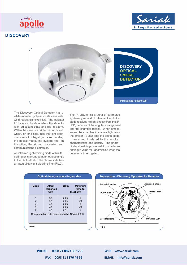
The Discovery Optical Detector has a white moulded polycarbonate case with wind-resistant smoke inlets. The indicator LEDs are colourless when the detector is in quiescent state and red in alarm. Within the case is a printed circuit board which, on one side, has the light-proof chamber with integral gauze surrounding the optical measuring system and, on the other, the signal processing and communications electronics.
An infra-red light emitting diode within its collimator is arranged at an obtuse angle to the photo-diode. The photo-diode has an integral daylight-blocking filter (Fig.2).
The IR LED emits a burst of collimated light every second. In clear air the photo-diode receives no light directly from the IR LED, because of the angular arrangement and the chamber baffles. When smoke enters the chamber it scatters light from the emitter IR LED onto the photo-diode in an amount related to the smoke characteristics and density. The photo-diode signal is processed to provide an analogue value for transmission when the detector is interrogated.
Part Number 58000-600
DISCOVERYOPTICAL SMOKE DETECTOR
Optical Chamber Address Buttons
PCB Cover Photo-Diode
Infra-Red LED
Top section - Discovery Optical smoke Detector
Case Moulding
Fig. 2
Optical detector operating modes
Mode
Alarm dB/m
Minimum threshold time to
%/m (seca)larm
1 1.4 0.06 52 1.4 0.06 303 2.1 0.09 54 2.1 0.09 305 2.4 0.11 5
Compensation rate complies with EN54–7:2000
Table 1

The Discovery multisensor construction is similar to that of the optical detector but uses a different lid and optical mouldings to accommodate the thermistor (heat sensor). The sectional view (Fig 3) shows the arrangement of the optical chamber and the thermistor.
The Discovery Optical/heat multisensor detector contains an optical smoke sensor and a thermistor temperature sensor whose outputs are combined to give the final analogue value. The way in which the signals from the two sensors are combined depends on the response mode selected. The five modes provide response behaviour which incorporates pure heat detection, pure smoke detection and a combination of both. The multisensor is therefore useful over the widest range of applications.
The signals from the optical smoke sensing element and the temperature sensor are independent, and represent the smoke level and the air temperature respectively in the vicinity of the detector. The detector’s micro-controller processes the two signals according to the mode selected. When the detector is operating as a multisensor (i.e. modes 1, 3 and 4) the temperature signal processingextracts only rate-of-rise information for combination with the optical signal. In these modes the detector will not respond to a slow temperature increase – even if the temperature reaches a high level. A large sudden change in temperature can, however, cause an alarm without the presence of smoke, if sustained for 20 seconds.
Additional heat sensor information
Discovery optical/heat multisensor detectors manufactured from mid 2009 incorporate additional temperature information that is intended for use in signal processing.
Temperature data can be read separately by the control panel (see Note 1) and used to validate an alarm signalled by the multisensor analogue value. An example of this would be a high multisensor analogue value not accompanied by an increase in heat: this would indicate that an agent other than smoke, e.g. steam, had caused the high analogue value.
The exact method of polling to make use of this feature is described in a Technical Sales document available to panel partners.
This feature offers protection from false alarms.
OPERATING PRINCIPlES
Wrong photo. Please use photo to be sent.
Part Number 58000-700
DISCOVERY
OPTICAL/HEAT MULTISENSOR DETECTOR
sectional view - Discovery Multisensor Detector Multisensor Detector operating modes
Fig. 3 Table 2
Mode
Smoke Sensitivity
(grey smoke)%/m dB/m
Temperature Sensitivity(relative)
Response Type
Minimum Time to Alarm(seconds)
1 1.1 0.05 h igh multisensor 20
2 2.1 0.09Not set to heat
responseOptical 30
3 2.8 0.12 Low multisensor 20
4 4.2 0.19 h igh multisensor 20
5No response
to smokeSee mode 5
oppositeh eat A1R 15
PCB Twin Alarm LEDs RFI shield
External moulding
Chamber cut away to reveal optical bench
ThermistorOptical chamber
DISCOVERY
PHONE
FAX
WEB
0098 21 8873 38 12-3
0098 21 8876 44 55
www.sariak.com

Discovery heat detectors have a common profile with ionisation and optical smoke detectors but have a low air flow resistance case made of self-extinguishing white polycarbonate.
The Discovery h eat Detector uses a single thermistor to sense the air temperature at the detector position. The thermistor is connected in a resistor network, which produces a voltage output dependent on temperature. The design of the resistor network, together with the processing algorithm in the microcontroller, gives an approximately linear characteristic from 10°C to 80°C. This l inearised signal is further processed, depending on the response mode selected, and converted to an analogue output.
For the European standard version of the detector, the five modes correspond to five “classes” as defined in EN54–5:2001. The classes in this standard correspond with different response behaviour, each of which is designed to be suitable for a range of application temperatures. All modes incorporate “fixed temperature” response, which is defined in the standard by the “static response temperature”. The application temperatures and static response temperatures for all response modes are given in Table 6.
In addition to the basic classification, a detector may be given an “R” or “S” suffix. The “R” suffix indicates that the detector has been shown to have a rate-of-rise characteristic. Such a detector will still give a rapid response even
when start ing from an ambient temperature well below its typical application temperature. This type of detector is therefore suitable for areas such as unheated warehouses in which the ambient temperature may be very low for long periods.
The “S” suffix on the other hand indicates that the detector will not respond below its minimum static response temperature even when exposed to high rates of rise of air temperature. This type is therefore suitable for areas such as kitchens and boiler rooms where large, rapid temperature changes are considered normal.
OPERATING PRINCIPlES
Part Number 58000-400
DISCOSERY HEAT DETECTOR
sectional view - Discovery Heat Detector
Fig. 5
Address Buttons Thermistor Bead
PCB
Case Moulding
Heat shrink sleeving
Lid Moulding
LEDLED
Heat Detector Response Modes
Table 6
Mode
Class(EN54–5:2001)
ApplicationTemperatureTypical Max
Static ResponseTemperature °C
Min Typ Max
1 A1R 25 50 54 57
65
2 A2R 25 50 54 61 70
3 A2S 25 50 54 61 70
4 CR 55 80 84 90 100
5 CS 55 80 84 90 100
For air temperatures in the range 15°C to 55°C, the analogue value for a detector in mode 1 will correspond approximately to the air temperature.
DISCOVERY
PHONE
FAX
WEB
0098 21 8873 38 12-3
0098 21 8876 44 55
www.sariak.com

points respond by providing a value of 64 which corresponds to the alarm value. The panel should recognise this response as a test signal and should not raise a general alarm.
Discovery manual Call Points are available with or without an isolator. Each version is available with a resettable element and a backbox for surface mounting as standard. If a glass option is required, spare glasses are available on request. For all part numbers please refer to table 7.
For ease of installation Discovery manual call points are supplied with clip-on terminal blocks and a connector which allows continuity testing before call points are commissioned.
To provide additional protection against accidental operation, a transparent hinged cover with a locking tag, part number 26729-152 is available, which can be fitted to the manual call point. Please note that the call point does not conform to EN54-11:2001 when this lid is fitted and secured with the locking tag.
The Apollo Discovery EN54–11:2001 compliant manual Call Point ( mCP) is based on the KAC conventional mCP range. It is electronically and mechanically compatible with previous Apollo call points based on KAC’s World Series product.
The address of each call point is set at the commissioning stage by means of a seven-segment DIL switch.
If an mCP is activated, it interrupts the normal protocol to give a fast response.
A single bi-coloured alarm LED is provided on the call point. This LED is controlled, independently of the call point, by the control panel and may be set to flash each time the call point is polled. The red LED is lit when the call point has been activated and sent into alarm. On the isolated versions an amber/yellow LED indicates a short circuit on the loop wiring either side of the call point.
Call points can be remotely tested from the panel by transmission of a single bit in the communications protocol. Call
WATERPROOF AND NON-STANDARD MANUAl CAll POINTS
Discovery waterproof (IP67) manual call points are available in red or yellow. For special purposes, such as initiating a ‘h azard’ alarm, specially coloured call points can be used on the fire system – see table opposite. h owever, these do not conform to EN54-11:2001 requirements.
Part Number see Table 7
DISCOSERY MANUALCALL POINT
OPERATING PRINCIPlES
DISCOVERY
PHONE
FAX
WEB
0098 21 8873 38 12-3
0098 21 8876 44 55
www.sariak.com
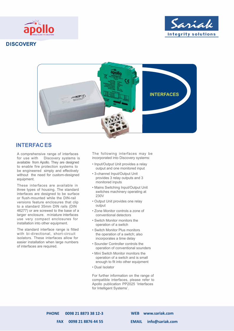
A comprehensive range of interfaces for use with Discovery systems is available
from Apollo. They are designed
to enable fire protection systems to be engineered simply and effectively without
the need for custom-designed
equipment.
These interfaces are available in three types of housing. The standard interfaces are designed to be surface or flush-mounted while the DIN-rail versions feature enclosures that clip to a standard 35mm DIN rails (DIN 46277) or are screwed to the base of a larger enclosure. m iniature interfaces use very compact enclosures for installation into other equipment.
The standard interface range is fitted with bi-directional, short-circuit isolators. These interfaces allow for easier installation when large numbers of interfaces are required.
The following interfaces may be incorporated into Discovery systems:
• Input/Output Unit provides a relayoutput and one monitored input
• 3-channel Input/Output Unitprovides 3 relay outputs and 3monitored inputs
• Mains Switching Input/Output Unitswitches machinery operating at230V
• Output Unit provides one relayoutput
• Zone Monitor controls a zone ofconventional detectors
• Switch Monitor monitors theoperation of a switch
• Switch Monitor Plus monitorsthe operation of a switch; alsoincorporates a time delay
• Sounder Controller controls theoperation of conventional sounders
• Mini Switch Monitor monitors theoperation of a switch and is smallenough to fit into other equipment
• Dual Isolator
For further information on the range of compatible interfaces, please refer to Apollo publication PP2025 ‘Interfaces for Intelligent Systems’.
INTERFAC ES
INTERFACES
DISCOVERY
PHONE
FAX
WEB
0098 21 8873 38 12-3
0098 21 8876 44 55
www.sariak.com

The Discovery® Open Area Sounder
Beacon is an alarm device comprising
a sounder, a beacon and a short-
circuit isolator for use with Discovery
detection systems. It is supplied with
a mounting base which incorporates a
short-circuit isolator.
Application
The Discovery Open Area Sounder
Beacon is used to provide audible
and visual warning of fire and is
controlled by the fire control panel
by means of the Discovery protocol.
The particular features of this sounder
beacon are available only when it is
being controlled by the full Discovery
protocol with the panel programmed
accordingly. Information on available
features should be requested from the
panel manufacturer.
Features & advantages
These are identical to the Discovery
Sounder Beacon Base but the Open
Area Sounder Beacon is a wall-
mounted stand-alone device that
produces a higher sound output of up
to 100dB(A).
Part Number 58000-005 (red)58000-007 (white)
DISCOSERY
OPEN AREA S OUNDER BEACON
Discovery Open Area sounder Beacon
Part No 58000-005 (red), 58000-007 (white)specifications are typical at 24v, 23°C and 50% relative humidity unless otherwise stated.
Operating voltage:
17–28V DC (polarity sensitive)
Protocol pulses: 5–9V
Current consumption at 24V:
switch-on surge, <1s
1.2mAquiescent
350µAdevice operated at maximum volume
8.2mA
Maximum sound output at 90°:
100dB(A) Sound pressure level data is published in PIN sheet PP2203 available from Apollo
Operating temperature:
–20°C to +60°C
Humidity (no condensation or icing):
0–95%
IP rating: 65
TECHNICAL DATA
DISCOVERY
PHONE
FAX
WEB
0098 21 8873 38 12-3
0098 21 8876 44 55
www.sariak.com

When lives and property are at risk and you need gas detection
equipment that is totally reliable, you need Crowcon. For over 45
years Crowcon has been developing and manufacturing high quality
products with a reputation for reliability and technical innovation.
Crowcon fixed-point detectors have been proven in many arduous
environments, including oil and gas exploration and production,
petrochemicals, water treatment, chemical plants and steel mills.
XgardIQ provides fail-safe detection of a very wide range of gases
and vapours.
XgardIQ is an intelligent and versatile gas detector and transmitter compatible with Crowcon’s full range of sensor
technologies. XgardIQ is available fitted with a variety of flammable, toxic and oxygen gas sensors and provides a
bright OLED display with clear and comprehensive status information in a range of languages.
Confidence with Positive Safety
Bright LEDs indicate detector status at a glance; the unique Positive Safety LED confirms the detector is operating
safely and alerts operators to any irregular events that may affect product integrity such as the ambient temperature
exceeding sensor limits. When working safely, the blue LED remains on constantly. If any abnormal conditions are
detected the LED will flash and a warning message will be displayed.
Flexible signal outputs
XgardIQ provides comprehensive and powerful output signal options; analogue 4-20mA signal with auto sink/source
detection feature and RS-485 Modbus communications are provided as standard. Alarm and fault relays featuring
heavy-duty changeover contacts, rated 230Vac 5A, are available at purchase or may be added at any time after
installation. HART communications can be provided both over the analogue signal and via local I.S. terminals for
diagnostics via any HART asset management system or hand-held device.
Rugged and robust
ATEX and IECEx certified for use in Zone 1 and Zone 2 hazardous areas, XgardIQ has been designed for long-life
operation in extreme environments. Featuring a rugged 316 stainless steel construction and a wide operating
temperature range from -40°C to +75°C, XgardIQ is suitable for the most demanding applications.
Improved safety
XgardIQ minimises the time personnel spend in potentially hazardous locations
by using simple hot-swappable sensor modules. Sensors can be bump tested and
calibrated in-situ or removed in seconds using one hand, and either replaced with
a pre-calibrated sensor module or re-calibrated in a safe area before being re-
fitted. All functions and adjustments can be made via the integral keypad without
the need for special tools or hot-work permits.
CROWCON
PHONE
FAX
WEB
0098 21 8873 38 12-3
0098 21 8876 44 55
www.sariak.com

XgardIQ Options
• Pre-calibrated flammable,
toxic or oxygen sensor module
•Huge range of gas sensors.
Transmitter with Sensor
• Enables transmitter to be
installed in advance of com
missioning• Supplied with a dummy sensormodule for weather protection• Auto-configure function whenthe sensor module is plugged in.
Enables diagnostics via asset
management systems
• Local I.S. HART terminal
connection
• Detectors can be installed on
a HART addressable network.
HART Communications
•Simple plug-in module
• Heavy-duty 230Vac, 5A
contacts
• Alarm 1, Alarm 2 and Fault
relays
•On-delay and off-delay timers
• Can be retrofitted as needed.
Relays
XgardIQ is compatible with Crowcon’s full range of sensor technologies. The transmitter provides analogue 4-20mA and RS-485
Modbus signals as standard and HART communications is available as an option. A relay module may be fitted at the time of
purchase, or retrofitted at any time. The 316 stainless steel enclosure has three cable entries suitable for either M20 or ½”NPT
cable glands.
If XgardIQ is to be installed months ahead of scheduled commissioning, it can be supplied without a sensor module to avoid the
possibility of the sensor being poisoned or expiring whilst inactive. The transmitter is supplied with a dummy sensor module to
maintain dust and water ingress protection and sensor modules can be delivered and installed prior to commissioning.
Status LEDs
Positive Safety LED
Bright OLED display
Function buttons
CROWCON
PHONE
FAX
WEB
0098 21 8873 38 12-3
0098 21 8876 44 55
www.sariak.com

When lives and property are at risk and you need gas detectio n
equipment that is totally reliable, you need Crowcon. For over 40
years Crowcon has been developing and manufacturing high qualit y
products with a reputation for reliability and technical innovation.
Crowcon fixed detectors have been proven in many arduous
environments, including oil and gas exploration, water treatment,
and steel and chemical plants. IRmax offers uniquely low powered,
fail-safe detection of hydrocarbon gases and vapours.
Choosing the fixed gas detector for your needs
Simple to install
Compact size
Various installation options
Industry standard 4-20mA output
Options for HART communications and RS-485 Modbus
Requires less space, effort and time to install
Can be wall mounted, fitted to a 50mm (2 inch) pipe or connected to an auxiliary
junction box using a choice of mounting acessories
IRmax is compatible with virtually any control system
Easy maintenance
Remote non-intrusive calibration
Hand-held Intrinsically Safe (I.S) calibrator
The IR Display can be mounted up to 30 metres from the IRmax and test gas can
be applied without requiring direct access to the detector
IRmax detectors fitted with an I.S barrier module can be checked and calibrated
using an I.S calibration accessory
Prevents condensation on optical components
Low cost of ownership
Low power IRmax only consumes 1W of power, enabling small power supplies and battery back
and many other hydrocarbon gases and vapours.
The reliability of IRmax has been proven in hot, cold, wet and saline environments, making it ideal for use offshore. Unlike conventional IR
gas detectors, IRmax does not utilise heaters to prevent condensation on windows and mirrors. IRmax’s unique S
components are treated with a highly durable coating that completely prevents faults due to condensation. As IRmax contains no
components for artificially heating optical surfaces, power consumption is dramatically reduced, requiring only 1W of power, typicall
75-90% lower than conventional IR gas detectors.
up systems to be used
Please see the back page for full technical specifications.
Automatic optical obscuration monitoring
Annual proof-test interval
CROWCON
PHONE
FAX
WEB
0098 21 8873 38 12-3
0098 21 8876 44 55
www.sariak.com
TAY-CL IR optical

IRmax is available either as a basic unit without display, or with three display options. The Fixed IR Display is permanently fixed to the IRmax
detector to enable simple status checking and non-intrusive calibration. The Remote IR Display can be mounted up to 30 metres from
the IRmax detector, simplifying checking and maintenance of detectors mounted in inaccessible areas. The Hand-Held I.S. Calibrator is
available for temporary connection to IRmax detectors fitted with an I.S. Barrier Module.
I.S Hand-Held Calibrator
• Enables calibration and interrogation of IRmax
detectors without a Fixed or Remote IR Display
• Only one I.S. hand-held calibrator required per
IRmax detector fleet
• Intrinsically Safe; suitable for use in hazardous
• Can be mounted up to 30 metres from IRmax
• Removes the need to directly access the IRmax
detector
•
Fixed IR Display
Choice of connection lead lengths
Large, clear display shows gas level and other
status information
Simple non-intrusive calibration
Enables connection of hand-held HART
communicators
•
•
•
• Can be rotated up and down to provide the
optimum viewing angle
IRmax options
HART communications
• Hand-held HART communicators can be
connected to the IR Display for local
diagnostics and calibration
• HART data is super-imposed onto the 4-20mA
signal for communicating with HART enabled
control systems
• Compatible with point-to-point or addressable
HART topologies
RS-485 Modbus
• Enables remote interrogation of IRmax
• Enables up to 32 detectors to be multi-dropped
on an addressable network
• RS-485 physical platform for transmission of data
up to 1Km
Calibration cap
Mounting bracket kit
Spigot gland
Remote calibration unit Flow adaptor
Duct mounting kit
I.S remote display connecting leads
Accessories
Auxillary junction box
PHONE
FAX
WEB
0098 21 8873 38 12-3
0098 21 8876 44 55
www.sariak.com
CROWCON

The Solution F1 Fire Control Panel range is a new generation, modular and ultramodern Fire Control Panel range.These have been developed to meet international standards and to satisfy specific international requirements at the highest level.These panels contain numerous new features – several are unique in the security business – and they convince by their comprehensive equipment.Many optional (at extra cost) features in other panels are included in the “Solution F1” standard configuration.This range has been designed to be a universal and flexible product in terms of both the different configuration possibilities as well as the front fascia design. It thus meets the requirements for all possible applications.By the outstanding modularity of this panel it can be perfectly adapted to all anticipated user requirements. Flexibility – especially for connecting different detectors was one of the most important aims during the development of this new FireControl Panel.
Obviously it is a standard for this panel to connect nearly all conventional detectors of the market but very remarkable:The “Solution F1” panels are compatible to the newest analogue addressable detectors of Hochiki and Apollo –two of the biggest and best known players in the detector market worldwide.
■ Modular, intelligent Hybrid Fire Control Panel
Range
■ Supports Hochiki ESP and Apollo XP95 /
Discovery detectors
■ 2 – 18 loops in one standard housing
■ Brand new touch screen control panel
■ Graphics LCD module 240 x 64 as standard
included on basic model
■ Integral Power supply 24V DC with max. 7,5 A
or 4,0 A as standard included
■ 32 bit high performance CPU
■ Flash memory up to 8 MB and RAM memory
up to 8 MB
■ Many powerful features included
Addressable Fire Alarm Control Panel
PHONE
FAX
WEB
0098 21 8873 38 12-3
0098 21 8876 44 55
www.sariak.com

w w w .s m a r t e c h . c o m I n f o @ s m a r t e c h . c o m
Description of Addressable Fire Alarm Control Panel
LED : Description : green LED „In Operation“ The Fire Control Panel (FCP) is in operation.
green LED „Day Mode“ Indicates that the FCP is in „Day Mode“. That means the main alarm is delayed if a delay time is configured.
green LED „Night Mode“ Indicates that the FCP is in „Day Mode“. That means the main alarm is NOT delayed and any alarm activates the Fire Brigade immediately.
green LED „Service“ Indicates that the FCP is in „Service Mode“.
red LED „Main alarm“
Indicates that the FCP is in Alarm condition. See LC module for detailed information. If an alarm transmission device (TD) is connected to the panel the panel has tried to activate the TD.
red LED „Internal alarm“ Indicates that the FCP is in Alarm condition. See LC module for detailed information.
red LED „Fire Brigade alarmed“ Indicates that the FCP has activated the alarm transmission device (TD) to the Fire Brigade and the TD gave a response to confirm the activation. (Input
LED indications:
PHONE
FAX
WEB
0098 21 8873 38 12-3
0098 21 8876 44 55
www.sariak.com

§ 2 loop- each maximum 127 detectors/
module or alternative 8 stub line
§ 8 user programmable open collector
outputs
§ Cable shielding monitored for open and
short circuit to +/- wire
§ Earth fault detection
Loop Card for Solution F1 with 2 loops / 8 stub lines
Main Components
As loop card for Solution F1 with 2 loop/ 8 stub liens but additional with 100% redundancy. This means the microprocessor, the RAM and the operating system memory are doubled on this card. So there will be no failure in case of micro processer fault.
Redundant Loop Card for Solution F1 with 2 loops / 8 stub lines
w w w .s m a r t e c h . c o m I n f o @ s m a r t e c h . c o m
PHONE
FAX
WEB
0098 21 8873 38 12-3
0098 21 8876 44 55
www.sariak.com

Ø If for certain applications a higher reliability as
EN-54 and VdS standards is required – that will
be no problem for the
Ø “Solution F1” control panel: the Control
Processing Unit can be doubled as well as the
system boards which are responsible for the
communication with the sensors and which
passes the information from the detectors to the
CPU. So the user gets a 100% redundancy of his
whole system.
Ø But the R&D people did not stop the ambitious
aims for reliability there: They created a brand
new control panel technology with absolutely no
mechanical parts any longer which is unique in
the security business and which has a lot of
advantages for the installer as well as for the end
user.
Ø It contains a pressure sensitive piezo lacquer
and doesn't have to be adjusted. The surface
makes a worth-while impression because of it's
glass like design.
Ø This material is resistant against cleansing,
there is absolutely no attrition over years and
moreover it is very stable against EMC
influences.
The Reliability
Ø If for certain applications a higher reliability as EN-
54 and VdS standards is required – that will be no
problem for the
Ø “Solution F1” control panel: the Control Processing
Unit can be doubled as well as the system boards
which are responsible for the communication with the
sensors and which passes the information from the
detectors to the CPU. So the user gets a 100%
redundancy of his whole system.
Ø But the R&D people did not stop the ambitious aims
for reliability there: They created a brand new control
panel technology with absolutely no mechanical parts
any longer which is unique in the security business
and which has a lot of advantages for the installer as
well as for the end user.
Ø It contains a pressure sensitive piezo lacquer and
doesn't have to be adjusted. The surface makes a
worth-while impression because of it's glass like
design.
Ø This material is resistant against cleansing, there is
absolutely no attrition over years and moreover it is
very stable against EMC influences.
w w w .s m a r t e c h . c o m I n f o @ s m a r t e c h . c o m
PHONE
FAX
WEB
0098 21 8873 38 12-3
0098 21 8876 44 55
www.sariak.com

w w w .s m a r t e c h . c o m I n f o @ s m a r t e c h . c o m
§ Compatible to almost all conventional
detectors on the market
§ 32 detectors per line
§ 8 programmable open collector alarm outputs
§ Earth fault detection
§ Failure mode in case of microprocessor fault
Conventional detector card
As Conventional detector card for 8 stub lines but with 100 % redundancy.
That means the microprocessor, the Ram and the operating system memory are doubled on this card. So there will be no failure in case of microprocessor fault.
Conventional detector card with 100% redundancy for 8 stub lines
Main Components
PHONE
FAX
WEB
0098 21 8873 38 12-3
0098 21 8876 44 55
www.sariak.com

Relay card with 8 change over contacts
■ Compatible to fire detection system but
usable as a universal device in other
systems too
■8 programmable change over contacts,
each 250V AC / 5 A
■The modules can be plugged into a slot in the
Fire Control Panel. Data speed up to 64.000
bps and they use the Fire Control Panel
battery backup in case of mains failure.
Analogue or ISDN modem for operating the configuration software via telephone line
Main Components
PHONE
FAX
WEB
0098 21 8873 38 12-3
0098 21 8876 44 55
www.sariak.com

ADDRESSABLE LOOP
Optical Smoke Detector
Multi SensorHeat Detector
Remote Indicator
Manual Call Point
Dual Monitor Module for I.S. signaling devices Wall Sounder
Strobe
Loop Module
Moudbus
Mo
ud
bu
s
Intrinsically Safe Smoke Detector
Intrinsically Safe Heat Detector
Galvanic Isolator for I.S. detectors
Ex
Hazard Area
NSC SOLUTION F1
MICROPROSSESOR BASE
ADDRESSABLE FIRE ALARM
CONTROL PANEL
PHONE
FAX
WEB
0098 21 8873 38 12-3
0098 21 8876 44 55
www.sariak.com

Printer
Programing Monitoring
Beam Gas Detector Gas Detector
Flame Detector
Analogue Input( 4-20 mA)
Dig
ital In
pu
t
Sounder
Digital Output – 24Vdc
Flasher
Bell
LHD
Manual Call Point
PHONE
FAX
WEB
0098 21 8873 38 12-3
0098 21 8876 44 55
www.sariak.com
PHONE
FAX
WEB
0098 21 8873 38 12-3
0098 21 8876 44 55
www.sariak.com
info sariak.com@


