© IEOM Society
Finite element analysis of a car rocker arm
Tawanda Mushiri
D.Eng. Student; University of Johannesburg, Department of Mechanical Engineering, P. O. Box
524, Auckland Park 2006,
South Africa.
Lecturer; University of Zimbabwe, Department of Mechanical Engineering, P.O Box MP167, Mt
Pleasant, Harare
Charles Mbohwa
Professor and Supervisor; University of Johannesburg, Auckland Park Bunting Road Campus, P.
O. Box 524, Auckland Park 2006, Room C Green 5, Department of Quality and Operations
Management, Johannesburg, South Africa.
Abstract
High Density Polyethylene (HDPE) composite rocker arm has been considered for analysis owing to its light weight,
higher strength and good frictional characteristics. A 3-D finite element analysis was carried out to find out the
maximum stresses developed in the rocker arms made of steel and composite. From the results it was noted that almost
same stresses are developed for both the materials (steel and the composite). With this it may be concluded that the
stresses developed in the composite is well within the limits without failure. Therefore the proposed composite may
be considered as an alternate material for steel to be used as rocker arm.
Keywords High Density Polyethylene (HDPE), Rocker arm, finite element, modelling, simulation, steel, composite
1.0: Introduction A rocker arm is an oscillating lever that conveys radial movement from the cam lobe into linear movement at the
poppet valve to open it. One end is raised and lowered by a rotating lobe of the camshaft (either directly or via a tappet
(lifter) and pushrod) while the other end acts on the valve stem. When the camshaft lobe raises the outside of the arm,
the inside presses down on the valve stem, opening the valve. When the outside of the arm is permitted to return due
to the camshafts rotation, the inside rises, allowing the valve spring to close the valve. The rocker arm is an important
component in the operation of internal combustion engine because of its responsibility in transferring the profile of
the camshaft into motion for opening and closing the intake and exhaust valves (Palomaki & Hoffman, 2003).
This mini project focuses on two different types of rocker arms; the existing rocker arm “from the factory” chrome
alloy steel rocker arm, and a Glass fibre reinforced High Density Polyethylene (HDPE) composite rocker arm of fuel
injection pump.
Both the rocker arms were modelled and analysed in Solid Works. The locations of stress concentrations were also
studied in hopes of eliminating them and any possible flaws that could cause failure. As well as optimizing the design
(Palomaki & Hoffman, 2003). In this project, an attempt has been made to find various stresses under extreme load
conditions for the two rocker arms (Mishra, 2014).
1.1 Background The rocker arm is an important part of the valve train in fuel injection systems. It actuates the valves through a fulcrum
using the lifter and the push rod. It also provide a means of multiplying the lift ratio. Recently there have been an
advancement in the research of materials used in construction of rocker arms. Researchers are looking for materials
that reduce noise, weight and have higher strength for efficient operation. The most popular materials used for
Proceedings of the 2015 International Conference on Operations Excellence and Service Engineering
Orlando, Florida, USA, September 10-11, 2015
687

© IEOM Society
construction of rocker arms are Steel, Aluminium, forged steel to Stainless steel, alloys and composites (Mishra,
2014). Finite element methods can be carried out to determine the stresses and make a comparison between steel and
composite materials to predict the failure modes.
As the turning point of the valve train, the rocker arm is basically a sophisticated lever that channels radial movement
from the cam lobe into linear movement at the valve. This is a highly critical process. Due to stresses and vibrations,
which are more prevalent during high-speed operation, rocker arms undergo deflection. Severe rocker arm deflection
causes inefficient engine performance, and often results in metal fatigue leading to increased wear and friction in the
valve train and eventually engine failure.
1.2 Problem statement Due to problems associated with steel rocker arms like cost and weight, there is need to consider other alternative
materials for steel. Analysis of the material properties is important before they can be implemented.
1.3 Main objective To perform a finite element analysis comparison of a rocker arm made of chrome alloy steel and that of HDPE
composite rocker arm.
1.4 Justification The rocker arm is a very important component of engine. Failure of part makes engine useless and also the procurement
and replacement of the rocker arm is costly. Researches done so far clearly indicates that the problem has not yet been
overcome completely and designers are still facing lot of challenges especially, stress concentration and effect of
loading and other factors. The finite element method is the most popular approach used for analysing fracture
mechanics problems. The finite element method is the most popular approach used for analysing fracture mechanics
problems.
2.0: Literature review The most popular materials used in the manufacture of rocker arms are chrome alloy steel, pure steel and aluminium
(Husain & Prof Siraj, 2013). Other materials used include anodised aluminium high strength alloy aluminium, chrome
moly steel and high strength alloy steel. (Yu & Xu, 2006) (Chung & Kim, 2010). Some rocker arms are made out of
glass fibre reinforced high density polyethylene composite (HDPE). There are also other composites like the metal
matrix and polymer matrix composites though they are not popular (Mishra, 2014).
2.1 Types of rocker arms There are various types of rocker arms, and the design specifications are not the same for different types of vehicles
(bikes, cars trucks, etc). Even for same type of vehicle category rocker arms differs in some way. Types of rocker arm
depend also on which type of Internal-combustion engine is used in a vehicle (i.e. Push Rod Engines, Over Head Cam
Engines etc (Husain & Prof Siraj, 2013)
A. Stamped Steel Rocker Arm- The Stamped Steel Rocker Arm is the most common style of production of
rocker arms. The manufacture of stamped steel rocker is the easiest and the cheapest because they are stamped
from one piece of metal. They use a turn-on pivot that holds the rocker in position with a nut that has a
rounded bottom. This is a very simple way of holding the rocker in place while allowing it to pivot up and
down (Husain & Prof Siraj, 2013).
B. Roller Tipped Rocker Arm- This type of a rocker arm is just as it sounds. It’s similar to the Stamped Steel
Rocker and they differ slightly in a way that you just add a roller on the tip of the valve end of the rocker
arm. This addition of a roller is to lessen the friction, for somewhat more power, and reduced wear on the
valve tip. The Roller Tipped Rocker Arm still uses the turn-on pivot nut and stud for simplicity. They can
also be cast or machined steel or aluminium (Husain & Prof Siraj, 2013).
C. Full Roller Rocker Arm- This type of a Roller Rocker Arm is not a stamped steel rocker. They are machined
and the materials used are either steel or aluminium. They replace the turn-on pivot with bearings. This type
of rocker arm still use the stud from the turn-on pivot but they don't use the nut. They have a very short shaft
with bearings on each end (inside the rocker) and the shaft is bolted securely in place and the bearings allow
the rocker to pivot (Husain & Prof Siraj, 2013).
D. Shaft Rocker Arms- This type of rocker arm is build off from the full roller rocker arm. They have a shaft
that goes through the rocker arms and sometimes the shaft only goes through 2 rocker arms and sometimes
688
© IEOM Society
the shaft will go through all of the rocker arms depending on how the head was manufactured. The importance
of the shaft is for rigidity. Putting a shaft through the rocker arms is much more rigid than just using a stud
from the head. The more rigid the valve train, the less the valve train deflection and the less chance for
uncontrolled valve train motion at higher RPM (Husain & Prof Siraj, 2013).
E. Centre Pivot Rocker Arms- In appearance, a centre pivot rocker arm looks like a traditional rocker arm but
there is a much bigger difference. Instead of the pushrod pushing up on the lifter, the Cam Shaft is moved
into the head and the Cam Shaft pushes directly up on the lifter to force the valve down. In this case the pivot
point is in the centre of the rocker arm and the Cam Shaft is on one end of the rocker arm instead of the
pushrod (Husain & Prof Siraj, 2013).
F. End Pivot (Finger Follower) Rocker Arms - The End Pivot or Finger Follower puts the pivot point at the end
of the Rocker Arm. In order for the Cam Shaft to push down on the Rocker Arm it must be located in the
middle of the rocker arm. (Husain & Prof Siraj, 2013)
2.2 Applications of Rocker arms A rocker arm is an important component and it is used in the operation of an internal combustion engine because it is
responsible for translating the profile of the camshaft into motion for opening and closing the intake and exhaust
valves. (Palomaki & Hoffman, 2003).
2.3 Causes of failure in rocker arms Failure analysis is a broad discipline that includes sectors of engineering such as metallurgy and mechanical
engineering. There are a number of failures that might occur, some appear more often than others, which include
various types of corrosion or wear by itself, corrosion in combination with wear, and compression to name a few.
Failure of engineered products and structures can occur by cyclic application of stresses (or strains), the magnitude of
which would be insufficient to cause failure when applied singularly. Structural and mechanical components subjected
to fluctuating service stress (or more appropriately, strain) are susceptible to failure by fatigue (Lee et al., 2008).
Fatigue is considered as one of the most common causes of structural and machinery component failures which are
frequently found in engineering services (Gagg & Lewis, 2009).
Fatigue failure is localised structural damage that occurs when a material is subjected to variable cyclic stresses. These
stresses are much lower than the ultimate tensile stress limit when under the application of a single static stress (Suresh,
2001).
3.0: Methodology This outlines the techniques that were employed in carrying out the finite element analysis of the two rocker arms of
different materials. It shows all steps taken done to fulfil the main objective of this project which is to check whether
HDPE composite material can be used as a substitute for steel in the construction of rocker arms.
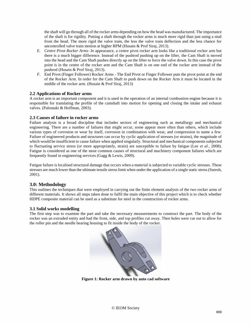
3.1 Solid works modelling The first step was to examine the part and take the necessary measurements to construct the part. The body of the
rocker was an extruded entity and had the front, side, and top profiles cut away. Then holes were cut out to allow for
the roller pin and the needle bearing housing to fit inside the body of the rocker.
Figure 1: Rocker arm drawn by auto cad software
689
© IEOM Society
3.2 Finite element model 3.2.1 Actual part loading
The pushrod internal combustion engine works by transferring a load through the rocker arm to open and close the
valve. To determine the load that would be seen by the rocker arm we found the spring rate that would be forcing
against the rocker arm. With the spring constant k, a cam profile that gave us the maximum lift of the valve and the
seat pressure of the valve, we were able to determine the maximum load on the rocker arm. The cam profile plots were
measured by a point of lift at every degree of rotation and can be seen in figures below. In both cases this load was
rounded up to be 1.4kN on the tip of the rocker and 2.2kN on the heal of the rocker. This was a static determination
of the loads in the rocker arms.
3.3 Experiment
An experiment was done to determine the loads that act on a rocker arm inside an engine. This assumes the
inertia loads which are not a maximum at the maximum lift point in the valve cycle would be negligible in
comparison to the spring load. Calculations below shows the calculations for the force on the rocker arm
due to the spring force. This was done by compressing the spring with a large screw and using a force scale
to measure the force exerted. These points were then recorded in Tables 1 and 2. The values obtained in the
tables were used to calculate the spring constant and obtaining the forces acting on the heal and tip of the
rocker arm.
Table 1: Stock spring rate determination
Lift (m) Force (N)
0.045 444.8
0.047 578.3
0.050 720.6
0.052 969.7
0.055 1156.5
0.057 1378.9
Table 2: Of high performance spring rate determination
Lift (m) Force (N)
0.045 622.8
0.047 756.2
0.050 911.9
0.052 1067.6
0.055 1236.6
0.057 1423.4
3.4: Calculations Calculations to find the spring constant k
𝑘 =∆𝑦
∆𝑥
For a largest possible triangle to determine the gradient which is k
k = 1378.9−444.8
0.057−0.045
From the calculation, the value of k is 77.8x10^3
3.4.1: Spring load calculationData given 444.8N of seat pressure on valve
77.8x10^3 as spring rate
1.5 as rocker ratio
valve lift = 0.00889*1.5
= 0.0133m
Ftip = 444.8 + 0.0133*77.8*10^3
= 1482.3N
Fheal = Ftip*rocker ratio
690
© IEOM Society
= 1482.3*1.5
= 2223.4N
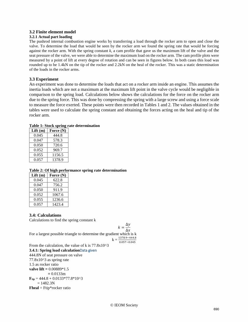
3.5: Loading in Model 3.5.1: Constrains
The rocker is constrained by a bolt through the pivot shaft which supports the rocker body by two roller bearings.
Since these bearings and shaft are not part of our study they were not included in the FEA. Fixed sliders were
introduced on both sides to avoid lateral movements on the part due to loading. The pivoting hole was also constrained
by a fixed hinge. These constraints should lead to an accurate model.
Figure 2: The rocker arm in simulation
The forces were applied at the tips and the heal of the rocker. This was applied to the model as the bearing load with
the force at the tip as 1.4kN and that on the heal being 2.2kN. These loads are accurate since they were taken from the
experiment and they will yield an accurate model.
3.6 FEA results After the finite element analysis was completed, the data was collected, and the two rockers were compared. In both
designs there are stress concentration areas. The results will be shown in the preceding chapters.
4.0: Finite element results and analysis 4.1 Results From the results of the finite element analysis done was observed that that maximum stresses are developed at sharp
corners of the rocker arm both on the HDPE rocker arm and the chrome alloy steel rocker arm. A side by side
comparison of stress values have been given for both the chrome alloy steel and composite rocker arms in table below.
For such a loading system of the rocker arm it is seen that there is very less difference in the stress values between
steel and composite.
Table 3: Stresses of steel rocker arm
Von Mises Stresses Node number Value in Pa
Maximum 1039 1.6x10^9
Minimum 1566 4.7x10^5
Table 4: Stresses of HDPE composite rocker arm
Von Mises Stresses Node number Value in Pa
Maximum 727 7.9 x 10^10
Minimum 27577 2.9 x10^7
The results are also depicted in the following figures. Detailed results which will show the deformations and other
parameters like the factor of safety and displacements from the finite element analysis will be shown in the reports
that will accompany this document.
691

© IEOM Society
Figure 3: Results of the rocker arm simulation done by Solid Works software with static stresses
692
© IEOM Society
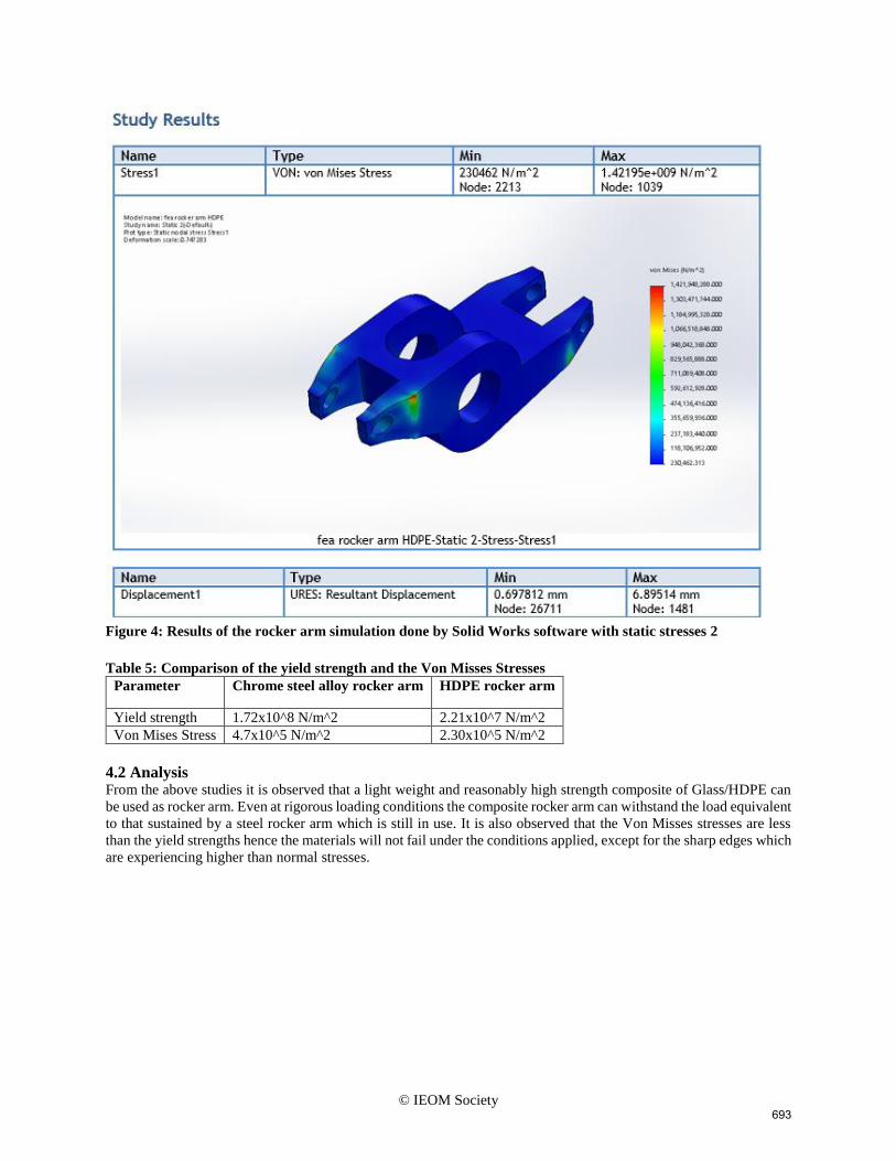
Figure 4: Results of the rocker arm simulation done by Solid Works software with static stresses 2
Table 5: Comparison of the yield strength and the Von Misses Stresses
Parameter Chrome steel alloy rocker arm HDPE rocker arm
Yield strength 1.72x10^8 N/m^2 2.21x10^7 N/m^2
Von Mises Stress 4.7x10^5 N/m^2 2.30x10^5 N/m^2
4.2 Analysis From the above studies it is observed that a light weight and reasonably high strength composite of Glass/HDPE can
be used as rocker arm. Even at rigorous loading conditions the composite rocker arm can withstand the load equivalent
to that sustained by a steel rocker arm which is still in use. It is also observed that the Von Misses stresses are less
than the yield strengths hence the materials will not fail under the conditions applied, except for the sharp edges which
are experiencing higher than normal stresses.
693
© IEOM Society
5.0: Recommendations and optimising 5.1 Recommendations and conclusion With the results of the chrome alloy steel and the composite rocker arm completed the next step was to analyse the
rocker arms with the goal of optimizing the part. Since there is a large stress concentration the sharp edges of the
rocker arms this cut will be eliminated and the neck of the rocker arm will be smoothed out. Given the results and
observations we got we concluded that the stresses developed in the composite is well within the limits without failure.
Therefore the proposed composite may be considered as an alternate material for steel to be used as rocker arm.
References Chung, C.-S. & Kim, H.-K., 2010. Safety evaluation of the rocker arm of a diesel engine. Journal of Materials &
Design, 31(2), pp. 940-945.
Gagg, C. R. & Lewis, P. R., 2009. In-service fatigue failure of engineered products and structures – Case study
review. Eng. Fail. Anal. s.l.:s.n.
Husain, S. M. & Prof Siraj, S., 2013. ROCKER ARM: - A REVIEW. International Journal of Innovative Research
in Science, Engineering and Technology, 2(4), pp. 1120-1126.
Maoveni, S., 1999. Finite Element Analysis Theory and Applications with ANSYS. New Jersey: Prentice Home
International.
Mishra, A., 2014. Stress Analysis of Glass/HDPE Composite Rocker Arm by Finite Element Method. International
Journal of Engineering Science and Innovative Technology, 3(3), pp. 212-218.
Palomaki, E. & Hoffman, K., 2003. Stock rocker versus roller rocker, New York: s.n.
Palomaki, E. & Hoffman, K., 2003. Stock Rocker vs Roller Rocker, New York: Rensselaer Polytechnic Institute.
Yu, Z. W. & Xu, X. L., 2006. Failure analysis of diesel engine rocker arms. Engineering Failure Analysis, 13(4), pp.
598-605.
Biography
Tawanda Mushiri received the B.Sc. (Hons) in Mechanical Engineering and M.Sc. Manufacturing Systems and
Operations Management degrees from University of Zimbabwe in 2008 and 2012, respectively. During 2008 – 2010,
he went on to do a Graduate Trainee Learner ship from Oil Company under the Ministry of Energy and Power
Development in Zimbabwe. He also worked as a Graduate Teaching Assistant at Chinhoyi University of Technology
from 2011 to early 2013 teaching machine intelligence and advanced control and robotics. He is now a lecturer at the
University of Zimbabwe from March 2013 to date teaching Engineering dynamics and design. He is a PhD student at
the University of Johannesburg doing automation.
Charles Mbohwa’s research activities and interests are in logistics, supply chain management, life cycle assessment
and sustainability, operations management, project management and engineering/manufacturing systems
management. His current Google Scholar h-index is 6 and Scopus h-index is 5. Currently is the Vice Dean of Research
at University of Johannesburg and a full professor.
694


