
FANUC FAST Ethernet FANUC FAST Data Server
OPERATOR’S MANUAL
B-64014EN/03
For FANUC Series 30*/300*, 31*/310*, 32*/320*-MODEL A

• No part of this manual may be reproduced in any form. • All specifications and designs are subject to change without notice. The export of this product is subject to the authorization of the government of the country from where the product is exported. In this manual we have tried as much as possible to describe all the various matters. However, we cannot describe all the matters which must not be done, or which cannot be done, because there are so many possibilities. Therefore, matters which are not especially described as possible in this manual should be regarded as ”impossible”. This manual contains the program names or device names of other companies, some of which are registered trademarks of respective owners. However, these names are not followed by or in the main body.
B-64014EN/03 SAFETY PRECAUTIONS
s-1
SAFETY PRECAUTIONS This section describes the safety precautions related to the use of CNC units, to ensure safe operation of machines fitted with FANUC CNC units. Read this section carefully before attempting to use any function described in this manual. Users should also read the relevant descriptions in the User’s Manual of the CNC to become fully familiar with the functions to be used.
Contents DEFINITION OF WARNING, CAUTION, AND NOTE ................s-2 GENERAL WARNINGS AND CAUTIONS....................................s-3

SAFETY PRECAUTIONS B-64014EN/03
s-2
DEFINITION OF WARNING, CAUTION, AND NOTE This manual includes safety precautions for protecting the user and preventing damage to the machine. Precautions are classified into Warnings and Cautions according to their bearing on safety. Also, supplementary information is described as Notes. Read the Warnings, Cautions, and Notes thoroughly before attempting to use the machine.
WARNING Applied when there is a danger of the user being
injured or when there is a danger of both the user being injured and the equipment being damaged if the approved procedure is not observed.
CAUTION
Applied when there is a danger of the equipment being damaged, if the approved procedure is not observed.
NOTE The Note is used to indicate supplementary
information other than Warning and Caution. • Read this manual carefully, and store it in a safe place.

B-64014EN/03 SAFETY PRECAUTIONS
s-3
GENERAL WARNINGS AND CAUTIONS WARNING
1 Before operating the machine, thoroughly check the entered data. Operating the machine with incorrectly specified data may result in the machine behaving unexpectedly, possibly causing damage to the workpiece and/or machine itself, or injury to the user.
2 Never attempt to machine a workpiece without first checking the programmed value, compensation value, current position, and external signal settings. Also, never attempt to machine a workpiece without first checking the operation of the machine. Before starting a production run, ensure that the machine is operating correctly by performing a trial run using, for example, the single block, feedrate override, or machine lock function, or by operating the machine with neither a tool nor workpiece mounted. Failure to confirm the correct operation of the machine may result in the machine behaving unexpectedly, possibly causing damage to the workpiece and/or machine itself, or injury to the user.
3 Ensure that the specified feedrate is appropriate for the intended operation. Generally, for each machine, there is a maximum allowable feedrate. The appropriate feedrate varies with the intended operation. Refer to the manual provided with the machine to determine the maximum allowable feedrate. If a machine is run at other than the correct speed, it may behave unexpectedly, possibly causing damage to the workpiece and/or machine itself, or injury to the user.
4 When using a tool compensation function, thoroughly check the direction and amount of compensation. Operating the machine with incorrectly specified data may result in the machine behaving unexpectedly, possibly causing damage to the workpiece and/or machine itself, or injury to the user.
5 The parameters for the CNC and PMC are factory-set. Usually, there is no need to change them. When, however, there is no alternative other than to change a parameter, ensure that you fully Failure to set a parameter correctly may result in the machine behaving unexpectedly, possibly causing damage to the workpiece and/or machine itself, or injury to the user.

SAFETY PRECAUTIONS B-64014EN/03
s-4
CAUTION 1 Immediately after switching on the power, do not touch
any of the keys on the MDI panel until the position display or alarm screen appears on the CNC unit. Some of the keys on the MDI panel are dedicated to maintenance or other special operations. Pressing any of these keys may place the CNC unit in other than its normal state. Starting the machine in this state may cause it to behave unexpectedly.
2 The operator's manual for FAST Ethernet / FAST Data Server describes all the basic functions of the CNC, including the optional functions. The selected optional functions vary with the machine. Some functions described in this manual may not, therefore, be supported by your machine. Check the machine specifications before using FAST Ethernet / FAST Data Server.
3 Some machine operations and screen functions are implemented by the machine tool builder. For an explanation of their usage and related notes, refer to the manual provided by the machine tool builder. For example: • On some machines, executing a tool function
causes the tool change unit to operate. When executing a tool function on such a machine, stand well clear of the tool change unit. Otherwise, there is a danger of injury to the operator.
• Many auxiliary functions trigger physical operations, such as rotation of the spindle. Before attempting to use an auxiliary function, therefore, ensure that you are fully aware of the operation to be triggered by that function.
NOTE Command programs, parameters, and variables are
stored in nonvolatile memory in the CNC. Generally, the contents of memory are not lost by a power on/off operation. However, the contents of memory may be erased by mistake, or important data in nonvolatile memory may have to be erased upon recovering from a failure.
To enable the restoration of data as soon as possible if such a situation arises, always make a backup of the data in advance.

B-64014EN/03 TABLE OF CONTENTS
c-1
TABLE OF CONTENTS
SAFETY PRECAUTIONS............................................................................s-1 DEFINITION OF WARNING, CAUTION, AND NOTE ............................................. s-2 GENERAL WARNINGS AND CAUTIONS............................................................... s-3
I. GENERAL
1 GENERAL ...............................................................................................3 1.1 ORGANIZATION ........................................................................................... 4 1.2 APPLICABLE MODELS................................................................................. 5 1.3 RELATED MANUALS.................................................................................... 6
II. SPECIFICATION
1 PREFACE................................................................................................9 2 DATA SERVER FUNCTIONS ...............................................................10
2.1 DATA SERVER FILE MANAGEMENT ........................................................ 11 2.1.1 File Names of CNC File Management ...................................................................12 2.1.2 Files which can be Created on a Data Server .........................................................13 2.1.3 Text Files and Binary Files ....................................................................................13
2.2 DATA SERVER MODES ............................................................................. 14 2.3 DETAILS OF THE BUFFER MODE............................................................. 16 2.4 OPERATION FROM A DATA SERVER ...................................................... 20 2.5 NC PROGRAM FORMAT............................................................................ 21 2.6 LIST FILE FORMAT .................................................................................... 22
3 FOCAS2/Ethernet FUNCTIONS...........................................................26 4 ABOUT DNS/DHCP ..............................................................................27 5 MACHINE REMOTE DIAGNOSIS FUNCTIONS...................................28
III. SETTING
1 SETTING THE COMMUNICATION FUNCTION ...................................31 2 SETTING THE DATA SERVER FUNCTIONS.......................................32
2.1 OPERATING THE DATA SERVER SETTING SCREEN............................. 33 2.2 RELATED NC PARAMETERS .................................................................... 42 2.3 EXAMPLE OF SETTING THE DATA SERVER FUNCTIONS ..................... 45

TABLE OF CONTENTS B-64014EN/03
c-2
3 SETTING THE FOCAS2/Ethernet FUNCTIONS ..................................46 3.1 OPERATING THE FOCAS2/Ethernet SETTING SCREEN ......................... 47 3.2 RELATED NC PARAMETERS .................................................................... 50 3.3 EXAMPLE OF SETTING THE FOCAS2/Ethernet FUNCTIONS.................. 51
4 SETTING THE DNS/DHCP FUNCTION................................................52 4.1 SETTING OF DNS....................................................................................... 53 4.2 SETTING OF DHCP.................................................................................... 55 4.3 RELATED NC PARAMETERS .................................................................... 58 4.4 EXAMPLE OF SETTING DNS/DHCP.......................................................... 59
4.4.1 When DNS/DHCP is Used with the Data Server ...................................................59 4.4.2 When DHCP is Used with the FTP Server Function of the Data Server ...............61 4.4.3 When DHCP is Used with the FOCAS2/Ethernet Function ..................................63
5 SETTING THE MACHINE REMOTE DIAGNOSIS FUNCTIONS ..........65 5.1 OPERATING THE MACHINE REMOTE DIAGNOSIS SETTING SCREEN. 66 5.2 RELATED NC PARAMETERS .................................................................... 72 5.3 CONTROLLING THE MACHINE REMOTE DIAGNOSIS FUNCTIONS
FROM THE PMC......................................................................................... 73 5.3.1 Signals ....................................................................................................................73 5.3.2 Signal Timing Charts..............................................................................................76
5.3.2.1 When the start of machine remote diagnosis is accepted................................... 76 5.3.2.2 When the start of machine remote diagnosis is rejected.................................... 77 5.3.2.3 When machine remote diagnosis is forcibly terminated.................................... 78
5.4 EXAMPLE OF SETTING THE MACHINE REMOTE DIAGNOSIS FUNCTIONS................................................................................................ 79
6 ERROR MESSAGES DISPLAYED DURING PARAMETER SETTING ...............................................................................................80
IV. OPERATION
1 OPERATING THE DATA SERVER FUNCTIONS.................................83 1.1 DEVICE CHANGE ON THE PROGRAM FOLDER SCREEN...................... 84 1.2 OPERATING THE DATA SERVER FILE LIST SCREEN ............................ 85
1.2.1 Displaying and Operating the File List ..................................................................90 1.2.2 File Transfer Operation ..........................................................................................94 1.2.3 Preparations for File Operation and Editing...........................................................95
1.3 OPERATING THE DATA SERVER HOST FILE LIST SCREEN ................. 97 1.3.1 Displaying and Operating the File List ................................................................100

B-64014EN/03 TABLE OF CONTENTS
c-3
1.3.2 File Transfer Operation ........................................................................................102 1.3.3 Preparations for File Operation ............................................................................104
1.4 M198-BASED SUBPROGRAM CALL........................................................ 105 1.5 DNC OPERATION..................................................................................... 107 1.6 NC PROGRAM INPUT .............................................................................. 108 1.7 NC PROGRAM OUTPUT .......................................................................... 109 1.8 FTP SERVER FUNCTIONS ...................................................................... 110
2 OPERATING THE MACHINE REMOTE DIAGNOSIS FUNCTIONS ..111 2.1 OPERATING THE MACHINE REMOTE DIAGNOSIS SCREEN............... 112
2.1.1 Selecting an Inquiry Destination ..........................................................................114 2.1.2 Starting Diagnosis ................................................................................................114
2.1.2.1 Diagnosis status ............................................................................................... 114 2.1.2.2 Error numbers and error messages................................................................... 115
2.1.3 Forcibly Terminating Diagnosis...........................................................................115
V. CONNECTION 117
1 SETTING .............................................................................................119 1.1 SPECIFICATIONS..................................................................................... 120 1.2 INSTALLATION ......................................................................................... 121
1.2.1 Installation on an LCD-mounted Type Unit.........................................................121 1.2.2 Installation on a Stand-alone Type Unit...............................................................122 1.2.3 Total Connection Diagram ...................................................................................123 1.2.4 Installing a Memory Card.....................................................................................124
2 CABLE CONNECTION .......................................................................126 2.1 CONNECTING TO Ethernet ...................................................................... 127 2.2 LEADING OUT THE Ethernet CABLE ....................................................... 128 2.3 100BASE-TX CONNECTOR (CD38R) PIN ASSIGNMENTS .................... 129 2.4 TWISTED-PAIR CABLE SPECIFICATION................................................ 130
2.4.1 Cable Connection .................................................................................................130 2.4.2 Cable Materials.....................................................................................................131 2.4.3 Connector Specification .......................................................................................133
2.5 ELECTRICAL NOISE COUNTERMEASURES.......................................... 134 2.5.1 Separating Signal Lines........................................................................................134 2.5.2 Clamping and Shielding Cables ...........................................................................134 2.5.3 Grounding the Network........................................................................................137
2.6 CHECK ITEMS AT INSTALLATION .......................................................... 139

TABLE OF CONTENTS B-64014EN/03
c-4
VI. MAINTENANCE
1 HARDWARE MAINTENANCE INFORMATION..................................143 1.1 BOARD...................................................................................................... 144
1.1.1 Component Layout ...............................................................................................144 1.1.2 LED Indications and Meanings ............................................................................145
2 SOFTWARE MAINTENANCE INFORMATION...................................148 2.1 Ethernet LOG ............................................................................................ 149 2.2 ETHERNET CONNECTION CONFIRMATION.......................................... 154 2.3 COMMUNICATION STATE CONFIRMATION........................................... 157 2.4 COMMUNICATION SOFTWARE CONFIRMATION.................................. 158
APPENDIX
A TROUBLESHOOTING ........................................................................163 A.1 CHECKING COMMUNICATION WITH A HUB.......................................... 164 A.2 CHECKING CONNECTION WITH THE TRUNK ....................................... 165 A.3 CHECKING SETTINGS............................................................................. 166 A.4 CHECKING COMMUNICATION................................................................ 167
B EXAMPLE OF FTP SERVER SETUP .................................................170 B.1 SETTING UP FTP SERVER OF Windows 2000 Professional
(FOR INTERNET INFORMATION SERVICE) ........................................... 171 B.2 SETTING UP FTP SERVER OF Windows XP Professional
(FOR INTERNET INFORMATION SERVICE) ........................................... 183
C EXAMPLE OF SETTING UP DNS/DHCP ...........................................207 C.1 EXAMPLE OF SETTING UP DHCP SERVER OF Windows 2000 Server. 208 C.2 EXAMPLE OF SETTING UP DNS SERVER OF Windows 2000 Server ... 215
D FTP CLIENT OPERATION..................................................................221 D.1 OPERATION USING THE FTP COMMAND.............................................. 222 D.2 SECURITY UNBLOCKING IN Windows XP (Service Pack 2) ................... 225

I. GENERAL


B-64014EN/03 GENERAL 1.GENERAL
- 3 -
1 GENERAL This part explains the organization of this manual.

1.GENERAL GENERAL B-64014EN/03
- 4 -
1.1 ORGANIZATION This manual consists of the following parts: SAFETY PRECAUTIONS This section describes the precautions to be observed when
reading this manual. I. GENERAL This part describes the chapter organization, applicable models,
and related manuals. II. SPECIFICATION This part describes the specifications of the functions that operate
on the FAST Ethernet/FAST Data Server. III. SETTING This part describes the method of setting. IV. OPERATION This part describes the method of operating the Data Server
functions and machine remote diagnosis functions. V. CONNECTION This part describes the method of connection and provides notes. VI. MAINTENANCE This part provides an Ethernet board drawing number and
describes the meanings of LED indications. APPENDIX These appendixes describe additional information such as that
related to troubleshooting, the operation of the FTP client, and how to set up the FTP server.

B-64014EN/03 GENERAL 1.GENERAL
- 5 -
1.2 APPLICABLE MODELS This Operator's Manual covers the following models. The abbreviations in the following table are sometimes used in text descriptions.
Model name Abbreviation FANUC Series 30i-MODEL A Series 30i-A 30i-A FANUC Series 300i-MODEL A Series 300i-A 300i-A FANUC Series 300is-MODEL A Series 300is-A 300is-A
30i-A
FANUC Series 31i-MODEL A FANUC Series 31i-MODEL A5
Series 31i-A 31i-A
FANUC Series 310i-MODEL A FANUC Series 310i-MODEL A5
Series 310i-A 310i-A
FANUC Series 310is-MODEL AFANUC Series 310is-MODEL A5
Series 310is-A 310is-A
31i-A
FANUC Series 32i-MODEL A Series 32i-A 32i-A FANUC Series 320i-MODEL A Series 320i-A 320i-A FANUC Series 320is-MODEL A Series 320is-A 320is-A
32i-A

1.GENERAL GENERAL B-64014EN/03
- 6 -
1.3 RELATED MANUALS The table below lists manuals related to this Operator's Manual. Refer to these manuals when you use this Operator's Manual. Related manuals of FANUC Series 30i/300i/300is, 31i/310i/310is, 32i/320i/320is -A
Manual name Specification number
DESCRIPTIONS B-63942EN CONNECTION MANUAL (HARDWARE) B-63943EN CONNECTION MANUAL (FUNCTION) B-63943EN-1 USER’S MANUAL (Common to Lathe System/Machining Center System)
B-63944EN
USER’S MANUAL (For Lathe System) B-63944EN-1 USER’S MANUAL (For Machining Center System) B-63944EN-2 MAINTENANCE MANUAL B-63945EN PARAMETER MANUAL B-63950EN Related manuals of FANUC CIMPLICITY i CELL
Manual name Specification number
OPERATOR’S MANUAL B-75074EN Related manuals of FANUC Machine Remote Diagnosis Package
Manual name Specification number
OPERATOR’S MANUAL B-63734EN

II. SPECIFICATION


B-64014EN/03 SPECIFICATION 1.PREFACE
- 9 -
1 PREFACE In this manual, a board that has an ATA Flash card or a Compact Flash Card (collectively called a memory card hereinafter) mounted to enable the use of the Data Server functions is referred to as a "FAST Data Server" (or simply as a "Data Server"). On the other hand, a board that does not have a memory card mounted is referred to as a "FAST Ethernet".
Board name Usable function
FAST Data Server (or simply referred to as "Data Server")
- Data Server functions - FOCAS2/Ethernet functions - CNC screen display functions - Machine remote diagnosis
functions
FAST Ethernet
- FOCAS2/Ethernet functions - CNC screen display functions - Machine remote diagnosis
functions
NOTE To use the Data Server functions, the Data Server
function option is required. To use the FOCAS2/Ethernet functions, CNC
screen display functions, and machine remote diagnosis functions, the Ethernet function option is required.
To use the CNC screen display functions, the CNC screen display function option is additionally required.

2.DATA SERVER FUNCTIONS SPECIFICATION B-64014EN/03
- 10 -
2 DATA SERVER FUNCTIONS The Data Server functions use a memory card built into a board for storing files and can transfer files and perform DNC operation using FTP. A Data Server can operate on both FTP client and FTP server. When you use a Data Server to transfer files, the Data Server operates as an FTP client and communicates with the FTP server on the host computer. When you use the host computer to transfer files, the Data Server operates as an FTP server and communicates with the FTP client on the host computer.
NOTE When the host computer operates as an FTP
server, FTP server software must be run on the host computer. When the host computer operates as an FTP client, FTP client software must be run on the host computer.

B-64014EN/03 SPECIFICATION 2.DATA SERVER FUNCTIONS
- 11 -
2.1 DATA SERVER FILE MANAGEMENT With the Data Server functions, you can format the built-in memory card in the CNC file management mode to manage NC programs.
CNC file management For NC programs managed in the CNC file management mode, memory operation such as custom macro commands and M98-based subprogram calling are available. Operate the NC programs using the PROGRAM FOLDER screen in the same way as for NC programs in the CNC memory. As a CNC external input/output device, DNC operation and M198-based subprogram calling are available. In this case, operate NC programs using the DATA SERVER FILE LIST screen.
PROGRAM FOLDER screen
DATA SERVER FILE LIST screen
CNC file management
Edit operation
File transfer operation
Memory operation
(DNC operation is also available.)
NOTE 1 The Data Server for the 30i-A allows editing and
memory operation of NC programs stored on the memory card, so the method of managing files on the memory card differs from the file management method of conventional Data Servers. Note that, therefore, the memory card of the 30i-A is not compatible with the memory cards of conventional Data Server models.
2 For operation and details of the PROGRAM FOLDER screen, refer to Chapter 11, "PROGRAM MANAGEMENT," in Part III, "OPERATION," in the "USER'S MANUAL (Common to Lathe System/Machining Center System) (B-63944EN)."
3 For operation and details of the DATA SERVER FILE LIST screen, refer to Chapter 1, "OPERATING THE DATA SERVER FUNCTIONS," in Part IV, "OPERATION."

2.DATA SERVER FUNCTIONS SPECIFICATION B-64014EN/03
- 12 -
2.1.1 File Names of CNC File Management You can assign a file name to a file managed in the CNC file management mode in the same way as for CNC memory. • Up to 32 characters • Alphabetic characters (in upper and lower cases), numeric
characters, and four symbols (+, -, _, and .)
NOTE 1 File names are case-sensitive. 2 Any file name or folder name cannot begin with a
period (.). 3 It is impossible to assign the same name to a file
and a folder.
File names and program numbers When a file name assigned to a file consists of uppercase O and a numeric value, the file name is treated as a program number. Values ranging from 1 to 9999 can be used. A value beyond this range cannot be used for a file name in the program number format. Example) File names that can be used as program numbers “O0123” Program number 123 “O0001” Program number 1 “O3000” Program number 3000 “O9999” Program number 9999 File names that cannot be used as program numbers “ABC” (Does not have the format "O plus a numeric value") “o123” (Does not begin with uppercase letter "O") “O123.4” (Uses a character other than numeric characters)
NOTE When files on a Data Server are managed by
program number, their program numbers always consist of "O" plus a 4-digit number. So, even if there are files managed with different file names such as "O1" and "O01" on a personal computer, their program numbers are regarded as the same when these files are transferred to the Data Server.

B-64014EN/03 SPECIFICATION 2.DATA SERVER FUNCTIONS
- 13 -
2.1.2 Files which can be Created on a Data Server In the initial status, the maximum number of files which can be created on a memory card on a Data Server is 2047 and the maximum file size is 512 MB. Each folder is counted as one file. The maximum number of files and the maximum file size can be changed using NC parameter No. 930. For details, see Section 2.2, "RELATED NC PARAMETERS," in Part III, "SETTING."
2.1.3 Text Files and Binary Files You can store the following two types of files on a memory card on a Data Server: text files and binary files. For a text file, memory operation and edit operation as well as DNC operation can be performed by selecting it as a main program. For binary files, only DNC operation is available, but binary input operation in the high-speed remote buffer A format is available. If NC data other than an NC program is not handled as a binary file, it may not be able to be input or output correctly. NC data punched and stored on a memory card on a Data Server from the CNC is automatically handled as a binary file. A file to be transferred from a personal computer to a memory card on a Data Server must be specified explicitly as a binary file. More specifically, for GET operation on a Data Server operation screen, you can use soft key [GET] or [BGET] to specify whether to handle the file as a text file or a binary file. When the Data Server is used as an FTP server, you can execute an ASCII (text file) command or a BIN (binary file) command on your personal computer (FTP client) to specify whether to handle the file as a text file or a binary file.
NOTE An NC program stored as a text file is converted to
an editable file format so that the file can be edited on the CNC. For this reason, when a text file is read from the host computer to the memory card on the Data Server, then the file is transferred to the host computer, binary compatibility can no longer be maintained.

2.DATA SERVER FUNCTIONS SPECIFICATION B-64014EN/03
- 14 -
2.2 DATA SERVER MODES Each Data Server mode determines the input or output destination when a Data Server is operated as a CNC external input/output device. You can select one of the following three modes.
NOTE Data Server modes are valid only when the Data
Server is operated as an external storage device of the CNC. In case of main program operation for editing and a memory operation and an M98-based subprogram call, programs on the memory card of the Data Server are selected regardless of the Data Server mode.
Storage mode
The memory card built into the Data Server is selected as the external input/output device. For example, when DNC operation or M198-based subprogram calling is executed, the relevant NC program is called from the memory card built into the Data Server. When input operation (read) is executed for the Data Server, the relevant NC program is read from the memory card built into the Data Server. Conversely, when NC program output operation (punch) is executed for the Data Server, the output NC program is written on the memory card built into the Data Server.
Data Server Memory card
CNC memory
Read
DNC operation
Punch
FTP mode The host computer connected to the Data Server is selected as the external input/output device. For example, when DNC operation or M198-based subprogram calling is executed, the relevant NC program is called from the host computer. When input operation (read) is executed for the Data Server, the relevant NC program is read from the host computer connected to the Data Server. Conversely, when NC program output operation (punch) is executed for the Data Server, the output NC program is directly written on the host computer.

B-64014EN/03 SPECIFICATION 2.DATA SERVER FUNCTIONS
- 15 -
Data Server
CNC memory
Read
DNC operation
Punch
Host computer
CAUTION
1 In the FTP mode, an NC program is transferred from the host computer to the CNC. For this reason, if the line is disconnected during communication for some reason such as noise on the network, the disconnection directly affects the CNC operation as compared with the storage mode. Before DNC operation in the FTP mode, surely take measures to prevent noise and make sure that good communication conditions are present.
2 When feed hold is performed during DNC operation in the FTP mode, communication with the host computer may be stopped. In this case, the host computer may disconnect the communication. Perform feed hold during a trial run and completely confirm that the communication with the host computer is not disconnected.
Buffer mode
The host computer connected to the Data Server is selected as the external input device. In the buffer mode unlike the FTP mode, however, areas on the memory card built into the Data Server are used as intermediate buffers. For details of the buffer mode, see Section 2.3, "DETAILS OF THE BUFFER MODE," which is the following section. As the external output device, the memory card built into the Data Server is selected. When NC program output operation (punch) is performed, the operation equivalent to that in the storage mode is performed.
Data Server Memory card
CNC memory
DNC operation
Punch
Read Intermediate
buffers
Host computer
NOTE With the 32i-A, the buffer mode cannot be used.

2.DATA SERVER FUNCTIONS SPECIFICATION B-64014EN/03
- 16 -
2.3 DETAILS OF THE BUFFER MODE In the buffer mode, two areas (areas A and B) are prepared on the memory card. While the NC program data stored in one area is being supplied to the CNC, the subsequent NC program data is read in the other area from the host computer using FTP transfer. When all data in the former area has been supplied to the CNC, the data in the latter area is supplied to the CNC. In the former area, which becomes empty, the subsequent NC program data is read from the host computer using FTP transfer. Repeating this operation enables an NC program larger than the capacity of the memory card to be handled. To use the buffer mode, however, the original NC program must be divided into some files on the host computer in advance. The size of a divided file must be smaller than half the remaining capacity of the memory card. If the size of a divided file is too large (for example, 100 MB or more), it takes much time to read the first file from the host computer and it also takes time until operation starts.
Using the buffer mode In the buffer mode, a file (such as Oxxxx) called by DNC operation or M198-based subprogram calling is a file list. The file list contains the names of files to be called in the order in which they are to be called. In the buffer mode, the Data Server sequentially calls the files specified in the file list from the host computer and supplies data to the CNC.
Contents of Oxxxx
file1 file2 file3 file4 file5
Hard disk get (FTP)
Program call Oxxxx Oxxxx
file1 file2 file3 file4 file5
file1 file2 file3 file4 file5
Memory card
Area A
Area B
CNC Data Server Host computer

B-64014EN/03 SPECIFICATION 2.DATA SERVER FUNCTIONS
- 17 -
Files (file1 to file5) specified in the file list on the host computer are stored on the memory card built into the Data Server using FTP transfer and supplied to the CNC. In the buffer mode, after the CNC issues a request to read an NC program to the Data Server, the specified file list is read from the host computer. When the first file has been read, the Data Server starts supplying data to the CNC. For this reason, it takes time from when the CNC issues a request to read a program to when the Data Server starts supplying data. While the Data Server is supplying the data in one area to the CNC, it stores data into the other area using FTP transfer. For this reason, divide the original program data so that two consecutive files can be contained on the memory card built into the Data Server. Although the data in one area has been supplied to the CNC, FTP transfer may not terminate for the other area. In this case, program calling terminates abnormally because the subsequent data cannot be supplied. You can use a parameter not to cause the abnormal termination. In the file list, you can specify any file name allowed by the host computer that consists of up to 255 single-byte alphanumeric characters. Be sure to specify at least one LF (0A in hexadecimal) or CR (0D in hexadecimal) following each file name in the file list to delimit the file names.
NOTE In the buffer mode, you can also register a new file
on the memory card built into the Data Server by the "NC program GET" or "NC program output" operation.
By this operation, however, the remaining capacity of the memory card built into the Data Server that is required for operation in the buffer mode may be exhausted, resulting in an error in DNC operation in the buffer mode.
For this reason, during DNC operation in the buffer mode, do not register any new file on the memory card built into the Data Server.
2.DATA SERVER FUNCTIONS SPECIFICATION B-64014EN/03
- 18 -
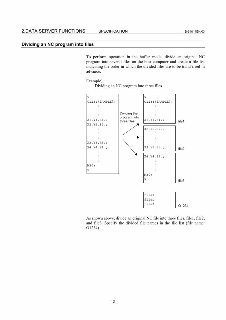
Dividing an NC program into files To perform operation in the buffer mode, divide an original NC program into several files on the host computer and create a file list indicating the order in which the divided files are to be transferred in advance. Example) Dividing an NC program into three files %
O1234(SAMPLE);
:
:
:
X1.Y1.Z1.;
%
O1234(SAMPLE);
:
:
:
X1.Y1.Z1.;
X2.Y2.Z2.;
:
:
:
X3.Y3.Z3.;
X4.Y4.Z4.;
:
:
:
M30;
%
X2.Y2.Z2.;
:
:
:
X3.Y3.Z3.;
X4.Y4.Z4.;
:
:
:
M30;
%
file1
file2
file3
file1
Dividing the program into three files
file2
file3
O1234
As shown above, divide an original NC file into three files, file1, file2, and file3. Specify the divided file names in the file list (file name: O1234).

B-64014EN/03 SPECIFICATION 2.DATA SERVER FUNCTIONS
- 19 -
CAUTION In the above example, the NC program is divided
into files so that any block is not divided. You can divide a program at a point in a block. When dividing a program at a point in a block, be careful so that any unnecessary character is not inserted at the end of each file.
If an unnecessary character is inserted at the end of a file, the NC program may perform unexpected operation when executed. Be very careful when preparing and editing an NC program on the host computer.
NOTE 1 Divide an NC program into files so that each file
size is about 20 to 30 MB. If the file size is too large, it takes time until DNC operation starts. If the file size is too small, data transmission may stop between files and operation may stop.
2 Although you can divide an NC program at a point in a block, divide the program in block units whenever possible and retract the tool at the end of each divided file. This prevents data transmission from stopping at the end of a file and cutter marking from being made.
3 Store the file list and relevant divided files in the same directory on the same host computer.

2.DATA SERVER FUNCTIONS SPECIFICATION B-64014EN/03
- 20 -
2.4 OPERATION FROM A DATA SERVER
Memory operation You can perform memory operation for an NC program on the memory card built into a Data Server in the same way as for an NC program in the CNC memory. You can also supply an NC program simultaneously for a multipath CNC system.
NOTE When memory operation is performed, a selected
program on the Data Server must be a text file. It is impossible to use a binary file for memory operation.
M198 subprogram operation
In the storage mode, you can perform M198 calling from the memory card built into a Data Server. In the FTP or buffer mode, you can perform M198 calling form the host computer. On the DATA SERVER FILE LIST screen, set an M198 folder in advance. When M198 calling is specified, the set M198 folder is searched for the target subprogram.
NOTE The file name of an NC program called by M198
must have the O number format.
DNC operation In the storage mode, you can perform DNC operation from the memory card built into a Data Server. In the FTP or buffer mode, you can perform DNC operation from the host computer. On the DATA SERVER FILE LIST screen, set the file name for DNC operation in advance. When DNC operation starts, the set DNC operation file is called.

B-64014EN/03 SPECIFICATION 2.DATA SERVER FUNCTIONS
- 21 -
2.5 NC PROGRAM FORMAT NC programs prepared on the host computer must have the following format: % TITLE ; O0001(COMMENT) ; ⋅ ⋅ ⋅ M30 ; %
An NC program starts with a start file mark (%). In the subsequent part (leader section) until EOB (;, program start) is encountered, a comment such as a title can be inserted as necessary. At the beginning of the program section, be sure to specify an O number or specify a file name consisting of up to 32 characters enclosed by "<" and ">". This O number or file name must be used for management on the personal computer. If an O number or a file name in an NC program is different from a file name on the personal computer, the file name used on the personal computer takes priority by default when the file is transferred from the personal computer to the Data Server. The semicolon ";" used at the end of each block means EOB (end of block) and actually functions as LF (LF: 0A in hexadecimal), CR-LF (CR: 0D in hexadecimal), or LF-CR-CR. The NC program must end with "M code ; %". When performing binary input operation, insert data for binary input operation, enclosed with the start code and end code of binary input operation, into the part ". . ." in the above figure. For details of binary input operation, refer to the relevant operator's manual of the CNC.
WARNING If an NC program prepared on the host computer
does not use the program format specified by the CNC, executing the NC program can cause an unpredictable operation. So, special care should be taken when an NC program is prepared on the host computer.

2.DATA SERVER FUNCTIONS SPECIFICATION B-64014EN/03
- 22 -
2.6 LIST FILE FORMAT In the LIST-GET, LIST-PUT, and LIST-DELETE functions described later, one of the following list file formats must be used:
Format 1 % ; O0001(COMMENT) ; N111 ; N222 ; N333 ; : : N999 ; % Format 2 % ; O0001(COMMENT) ; N111 (PC-File) ; N222 (PC-File) ; N333 (PC-File) ; : : N999 (PC-File) ; % Format 3 % ; O0001(COMMENT) ; (Dtsvr-File) ; (Dtsvr-File) ; (Dtsvr-File) ; : : (Dtsvr-File) ; % Format 4 % ; O0001(COMMENT) ; (Dtsvr-File, PC-File) ; (Dtsvr-File, PC-File) ; (Dtsvr-File, PC-File) ; : : (Dtsvr-File, PC-File) ; %

B-64014EN/03 SPECIFICATION 2.DATA SERVER FUNCTIONS
- 23 -
Specifications common to all formats <1> A list file begins with a start file mark "%". <2> In the next block, be sure to specify an O number. Assign this O
number as the file name. A comment enclosed in parentheses "(" and ")" can be inserted
between the O number and EOB. <3> In the subsequent blocks, specify files to be processed. <4> The list file must end with "%".
Specifications of format 1 The following describes the specifications of list file format 1: <1> This specification method applies when the file names of files to
be processed have the format "Oxxxx" (where "xxxx" denotes a 4-digit number). In this case, change "O" in file name "Oxxxx" to "N" when specifying the file name. The 4-digit number can be zero-suppressed. The example shows that files O0111, O0222, O0333, and so on up to O0999 are processed sequentially.
<2> The LIST-GET service transfers "Oxxxx" files stored on the built-in hard disk of the host computer to the built-in memory card of the FAST Data Server without modifying file names "Oxxxx". The LIST-PUT service transfers "Oxxxx" files stored on the built-in memory card of the FAST Data Server to the built-in hard disk of the host computer without modifying file names "Oxxxx". The LIST-DELETE service deletes "Oxxxx" files stored on the built-in memory card of the FAST Data Server.
Specifications of format 2
The following describes the specifications of list file format 2: <1> This specification method applies when files to be processed are
named "Oxxxx" (where "xxxx" denotes a 4-digit number) on the built-in memory card of the FAST Data Server and are named arbitrary file names on the built-in hard disk of the host computer. In this case, change "O" in file name "Oxxxx" to "N" when specifying the file name on the FAST Data Server. The 4-digit number can be zero-suppressed. The example shows that files O0111, O0222, O0333, and so on up to O0999 are processed sequentially.
A file name on the built-in hard disk of the host computer can be specified by enclosing it with parentheses "(" and ")" following the corresponding "Nxxxx". The characters that can be used in file names depend on the OS of the host computer.
<2> The LIST-GET service transfers files with arbitrary file names "PC-File" stored on the built-in hard disk of the host computer to the built-in memory card of the FAST Data Server as "Oxxxx" files. The LIST-PUT service transfers "Oxxxx" files stored on the built-in memory card of the FAST Data Server to the built-in hard disk of the host computer as files with arbitrary file names "PC-File". The LIST-DELETE service deletes "Oxxxx" files stored on the built-in memory card of the FAST Data Server.

2.DATA SERVER FUNCTIONS SPECIFICATION B-64014EN/03
- 24 -
Specifications of format 3 The following describes the specifications of list file format 3: <1> This specification method applies when the file names of files to
be processed are arbitrary file names. In this case, file names on the built-in memory card of the FAST Data Server and on the built-in hard disk of the host computer are assumed to be the same. Specify an arbitrary file name enclosed with parentheses "(" and ")". The characters that can be used in arbitrary file names are the following 66 ASCII characters only:
Numeric characters 0 to 9 Lowercase letters a to z Uppercase letters A to Z Four symbols (+, -, _, .) <2> The LIST-GET service transfers files with arbitrary file names
"Dtsvr-File" stored on the built-in hard disk of the host computer to the built-in memory card of the FAST Data Server with the file names kept unchanged.
The LIST-PUT service transfers "Dtsvr-File" files stored on the built-in memory card of the FAST Data Server to the built-in hard disk of the host computer with the file names "Dtsvr-File" kept unchanged. The LIST-DELETE service deletes "Dtsvr-File" files stored on the built-in memory card of the FAST Data Server.
Specifications of format 4
The following describes the specifications of list file format 4: <1> This specification method applies when files to be processed
have arbitrary file names. In this case, file names on the built-in memory card of the FAST Data Server and file names on the built-in hard disk of the host computer are assumed to be different. Specify a file name on the built-in memory card of the FAST Data Server and a file name on the built-in hard disk of the host computer in parentheses, separated by a comma ",".
The characters that can be used in file names on the built-in memory card of the FAST Data Server are the following 66 ASCII characters only:
Numeric characters 0 to 9 Lowercase letters a to z Uppercase letters A to Z Four symbols (+, -, _, .) The characters that can be used in arbitrary file names on the
built-in hard disk of the host computer depend on the OS of the host computer.
<2> The LIST-GET service transfers files with arbitrary file names "PC-File" stored on the built-in hard disk of the host computer to the built-in memory card of the FAST Data Server as "Dtsvr-File" files.
The LIST-PUT service transfers "Dtsvr-File" files stored on the built-in memory card of the FAST Data Server to files with file name "PC-File" on the built-in hard disk of the host computer.
The LIST-DELETE service deletes "Dtsvr-File" files stored on the built-in memory card of the FAST Data Server.

B-64014EN/03 SPECIFICATION 2.DATA SERVER FUNCTIONS
- 25 -
Limitations on file names in a list file The following limitations apply when file names are specified in a list file: <1> The characters that can be used in file names on the built-in
memory card of the FAST Data Server are the following 66 ASCII characters only:
Numeric characters 0 to 9 Lowercase letters a to z Uppercase letters A to Z Four symbols (+, -, _, .) The characters that can be used in arbitrary file names on the
built-in hard disk of the host computer depend on the OS of the host computer.
<2> Arbitrary file names may consist of up to 255 characters. However, the number of characters that can actually be used depends on the OS of the host computer.
Storage locations of list files
The LIST-GET, LIST-PUT, and LIST-DELETE services are useful functions for managing NC programs in groups. The places where list files are prepared vary depending on the service to be executed. For the LIST-GET service, NC programs to be operated on are present on the built-in hard disk of the host computer, so list files are placed also on the built-in hard disk of the host computer. For the LIST-PUT and LIST-DELETE services, NC programs to be operated on are present on the built-in memory card of the FAST Data Server, so list files are also prepared on the built-in memory card of the FAST Data Server.

3.FOCAS2/Ethernet FUNCTIONS SPECIFICATION B-64014EN/03
- 26 -
3 FOCAS2/Ethernet FUNCTIONS The FOCAS2/Ethernet functions can remotely control and monitor the CNC by using a personal computer. For details, refer to the manual delivered with the FOCAS2 library software.
NOTE In the FOCAS2/Ethernet functions, the CNC
operates as a server and waits for a communication start request from a personal computer that operates as a client.
As communication with the personal computer starts, two sockets are used for control and monitoring from the personal computer and for file transfer.

B-64014EN/03 SPECIFICATION 4.ABOUT DNS/DHCP
- 27 -
4 ABOUT DNS/DHCP If DNS/DHCP is used for communication setting of the Data Server functions and FOCAS2/Ethernet functions, Ethernet addresses (IP address and subnet mask) can be set at a time on the host computer to facilitate Ethernet address control.
DNS With the DNS function, a fully qualified domain name (e.g., www.fanuc.co.jp) can be specified instead of a hard-to-remember IP address just consisting of numbers (e.g., 192.168.0.10) when a TCP/IP communication destination is to be specified.
NOTE To use the DNS function, a personal computer
having the DNS server function is additionally required. See Chapter 4, "SETTING THE DNS/DHCP FUNCTION," in Part III, "SETTING," and APPENDIX C, "EXAMPLE OF SETTING UP DNS/DHCP."
DHCP
With the DHCP function, Ethernet addresses (IP address and subnet mask) that need to be set on the CNC can be set on the host computer.
NOTE To use the DHCP function, a personal computer
having the DHCP server function is additionally required. See Chapter 4, "SETTING THE DNS/DHCP FUNCTION," in Part III, "SETTING," and Appendix C, "EXAMPLE OF SETTING UP DNS/DHCP."

5.MACHINE REMOTE DIAGNOSIS FUNCTIONS SPECIFICATION B-64014EN/03
- 28 -
5 MACHINE REMOTE DIAGNOSIS FUNCTIONS
With the machine remote diagnosis functions, checking of the internal CNC status, ladder program editing, and other operations can be performed as necessary by using a personal computer through a LAN. For details, refer to “MACHINE REMOTE DIAGNOSIS OPERATOR’S MANUAL (B-63734EN).”

III. SETTING


B-64014EN/03 SETTING 1.SETTING THE COMMUNICATION FUNCTION
- 31 -
1 SETTING THE COMMUNICATION FUNCTION
This part describes the settings required to operate the following FAST Ethernet/FAST Data Server functions: • Data Server functions • FOCAS2/Ethernet functions • CNC screen display functions • Machine remote diagnosis functions
Notes on using the Data Server functions
CAUTION When setting the FAST Ethernet/FAST Data
Server for the first time, carefully set data such as an IP address and conduct a sufficient communication test, consulting with your network administrator.
If data such as an IP address is not set correctly, a communication failure can affect the entire network. Take sufficient care.

2.SETTING THE DATA SERVER FUNCTIONS SETTING B-64014EN/03
- 32 -
2 SETTING THE DATA SERVER FUNCTIONS
This chapter describes the communication setting for the Data Server functions.
Notes on using the functions for the first time
CAUTION 1 When using the FAST Data Server for the first time, be sure to
initialize the memory card, set parameters, then turn the power off then back on. If an attempt is made to use the Data Server functions without following these steps, normal operation is not guaranteed.
2 Before performing FTP communication using the FAST Data Server for the first time, consult with your network administrator, carefully set a network address and other items, and conduct communication tests thoroughly. Any error in settings such as a network address setting can lead to an adverse influence such as a communication failure on the entire network.
In particular, IP address duplication causes an intermittent communication failure in the Data Server, which can result in a system error in the CNC. So, be very careful when making settings.
3 When the power to the CNC is turned off during access to the memory card, files stored on the memory card may be destroyed. So, be careful not to turn off the power to the CNC during access to the memory card.
4 In preparation for damage to the memory card, always take backup copies of the files stored on the memory card to the host computer.
NOTE 1 With the Data Server functions (FTP client), a single CNC can
connect only one FTP server. 2 With the Data Server functions (FTP server), a single CNC can
connect up to five FTP clients. However, some FTP client software programs may each internally use two or more FTP clients. Note, therefore, that the number of FTP clients is not always equal to the number of applications.
3 The Data Server functions do not support passive mode (PASV command).

B-64014EN/03 SETTING 2.SETTING THE DATA SERVER FUNCTIONS
- 33 -
2.1 OPERATING THE DATA SERVER SETTING SCREEN This section describes the setting screen for operating the Data Server functions.
Procedure 1 Press the function key SYSTEM . 2 Soft key [ETHER BOARD] appear. (When there is no soft keys,
press the continue key.) 3 Press soft key [ETHER BOARD] to display the Ethernet Setting
screen. 4 Press soft keys [COMMON] and [DATA SERVER] and then
enter parameters for the items that appear.

2.SETTING THE DATA SERVER FUNCTIONS SETTING B-64014EN/03
- 34 -
COMMON screen (BASIC) Press soft key [COMMON] to display the COMMON screen (BASIC).
COMMON screen (BASIC)
Setting item
Item Description IP ADDRESS Specify the IP address of the FAST Data Server.
(Example of specification format: "192.168.0.100") SUBNET MASK Specify a mask address for the IP addresses of the
network. (Example of specification format: "255.255.255.0")
ROUTER IP ADDRESS
Specify the IP address of the router. Specify this item when the network contains a router. (Example of specification format: "192.168.0.253")
Display item
Item Description MAC ADDRESS FAST Data Server MAC address
NOTE The second page (detail screen) of the COMMON
screen is to be set when the DNS/DHCP function is used. For details, see "SETTING THE DNS/DHCP FUNCTION" provided later.

B-64014EN/03 SETTING 2.SETTING THE DATA SERVER FUNCTIONS
- 35 -
Data Server screens (CONNECT 1, CONNECT 2, CONNECT 3) Press soft key [DATA SERVER] to display the Data Server screen. By using page keys PAGE
PAGE , the three host computers at connection destinations 1, 2, and 3 can be set.
Data Server screens (for connection destination 1)
Setting item
Item Description HOST NAME Specify the IP address of the host computer.
(Example of specification format: "192.168.0.200") PORT NUMBER Specify the port number. Usually, set 21 because the
FTP communication is used. USER NAME Specify the name of the user to log on to the host
computer using FTP. (A user name of up to 31 characters can be specified.)
PASSWORD Specify the password for the above user name. The password must always be specified.
LOGIN FOLDER Specify a work folder to be used when the user logs in to the host computer. (Up to 127 characters can be specified.) If no data is set, the home folder set on the host computer is used as a login folder.

2.SETTING THE DATA SERVER FUNCTIONS SETTING B-64014EN/03
- 36 -
Operation Select a connection destination. 1 Press soft key [(OPRT)] to display soft key [HOST SELECT].
Then, press soft key [HOST SELECT] to display soft keys [CONECT 1], [CONECT 2], and [CONECT 3].
2 Press one of soft keys [CONECT 1], [CONECT 2], and
[CONECT 3] according to the host computer to which you want to make a connection. The screen title of connection destination 1, 2 or 3 is displayed in reverse video. The screen title displayed in reverse video indicates the connection destination host computer.
When connection destination 1 is selected

B-64014EN/03 SETTING 2.SETTING THE DATA SERVER FUNCTIONS
- 37 -
Data Server screens (FTP SERVER) Press soft key [DATA SERVER] to display the Data Server screen. By using page keys PAGE
PAGE , the FTP server setting screen is displayed after the connection destination 1, 2, or 3 screen.
Data Server screens (FTP SERVER)
Setting item Item Description
USER NAME Specify a user name to be used when the host computer logs in to the Data Server. (A user name of up to 31 characters can be specified.)
PASSWORD Specify the password for the above user name. The password must always be specified.
LOGIN FOLDER Specify a work folder to be used when the host computer logs in to the Data Server. (Up to 127 characters can be specified.) If no data is set, the home folder (home directory) is used as a login folder.

2.SETTING THE DATA SERVER FUNCTIONS SETTING B-64014EN/03
- 38 -
Data Server MODE screen (SETTING) Press soft key [DS MODE] to display the Data Server MODE screen (SETTING). The current mode can be checked and changed.
Data Server screen (SETTING)
Display item
Item Description CHANNELS Displays the number of channels currently being used.MODE Displays the currently set Data Server mode.
STORAGE MODE FTP MODE BUFFER MODE
Operation
The Data Server mode can be changed. 1 Press soft key [(OPRT)] to display soft keys [STRAGE MODE],
[FTP MODE], and [BUFFER MODE].
2 To change the mode to a desired mode, press the soft key of the
desired mode.
NOTE To use the buffer mode, the software option for
buffer mode functions is required.

B-64014EN/03 SETTING 2.SETTING THE DATA SERVER FUNCTIONS
- 39 -
Data Server MODE screen (MAINTENANCE) Press soft key [DS MODE] and press page keys PAGE
PAGE to display maintenance information for each channel.
Data Server MODE screen (MAINTENANCE)
Display item
Item Description CHANNEL Interface number of the buffer used for transferring NC
programs between the CNC and Data Server. For example, a channel is assigned to each path.
EMPTY COUNTER
Used for maintenance. This item indicates the number of cases where the buffer becomes empty while NC programs are being transferred from the Data Server to the CNC.
TOTAL SIZE Used for maintenance. This item indicates the total number of bytes transferred when an NC program is transferred from the Data Server.
WRITE POINTERREAD POINTER
Used for maintenance. This item indicates the buffer use status when NC programs are transferred from the Data Server to the CNC.

2.SETTING THE DATA SERVER FUNCTIONS SETTING B-64014EN/03
- 40 -
Data Server FORMAT screen Press soft key [DS FORMAT] to display the format screen of the memory card built into the Data Server.
Data Server FORMAT screen
Display item
Item Description DEVICE NAME Indicates the storage media currently being used by
the Data Server. "ATA" or "NONE" is indicated.
FORMAT TYPE Indicates the format type of the memory card. "CNC FILE" or "---" is displayed. When "---" is displayed, check whether the memory card is mounted properly and is formatted correctly.
CHECK DISK Indicates the check result. When no check is made : “-----“ When the check result is normal : “OK” When the check result is abnormal : “NG”

B-64014EN/03 SETTING 2.SETTING THE DATA SERVER FUNCTIONS
- 41 -
Procedure (CHECK DISK) 1 Press soft key [(OPRT)] then soft key [CHECK DISK].
2 Press soft key [EXEC] to check the format of the memory card
and display the check result.
CAUTION If the check result is abnormal, determine the
cause of trouble from an error message displayed on the ETHERNET LOG screen and back up the files stored on the memory card immediately. Then, try to reformat the memory card.
NOTE 1 An error occurs if other Data Server functions are
operated when a check disk is made. 2 Also when a program on the memory card of the
Data Server is selected as a main program, the check disk operation cannot be performed.
Procedure (CNC FORMAT)
1 Press soft key [(OPRT)] then soft key [CNC FORMAT].
2 Press soft key [EXEC] to format the memory card built into the
FAST Data Server.
CAUTION 1 Do not turn off the power to the CNC when the
memory card is being formatted. Otherwise, the memory card can be damaged.
2 When the memory card is formatted, all files held on the memory card are erased.
NOTE 1 An error occurs if other Data Server functions are
operated when the memory card is formatted. 2 Also when a program on the memory card of the
Data Server is selected as a main program, the memory card cannot be formatted.

2.SETTING THE DATA SERVER FUNCTIONS SETTING B-64014EN/03
- 42 -
2.2 RELATED NC PARAMETERS The NC parameters related to the Data Server functions are described below.
#7 #6 #5 #4 #3 #2 #1 #0
0000 TVC [Data type] Bit TVC When a file is transferred from the personal computer to the Data
Server, a TV check is: 0: Not performed. 1: Performed.
NOTE This parameter is valid only for text files. For text files, see Subsection 2.1.3, "Text Files and
Binary Files" in Part II, "SPECIFICATION."
0020 I/O CHANNEL : Input/output device selection [Data type] Byte [Valid data range] 5 : Selects the Data Server as the input/output device.
#7 #6 #5 #4 #3 #2 #1 #0
0100 NCR CRF CTV [Data type] Bit CTV When a file is transferred from the personal computer to the Data
Server, character counting for the TV check in program comment parts is: 0: Performed. 1: Not performed.
CRF When a file is output from the Data Server to the personal computer, EOB (end of block) is: 0: Set as specified by parameter NCR (bit 3 of parameter No. 100). 1: Set to "CR" "LF".
NCR When a file is output from the Data Server to the personal computer, EOB (end of block) is: 0: Set to "LF" "CR" "CR". 1: Set to "LF".
NOTE This parameter is valid only for text files. For text files, see Subsection 2.1.3, "Text Files and
Binary Files" in Part II, "SPECIFICATION."

B-64014EN/03 SETTING 2.SETTING THE DATA SERVER FUNCTIONS
- 43 -
#7 #6 #5 #4 #3 #2 #1 #0
0904 LCHK BWAT [Data type] Bit LCHK In the LIST-GET service of the Data Server, when a list file specifies
1025 or more files: 0: A check for duplicated file names is performed. 1: A check for duplicated file names is not performed.
BWAT If FTP communication is behind data supply during DNC operation in the buffer mode of the Data Server: 0: An error is caused. 1: No error is caused and DNC operation continues after waiting the
completion of FTP communication.
#7 #6 #5 #4 #3 #2 #1 #0
0905 DSFN PCHK [Data type] Bit DSFN When a program is stored on the memory card of the Data Server:
0: The file name takes priority. 1: The program name in the NC program takes priority.
PCHK At the start of communication of the Data Server or machine remote diagnosis functions, checking for the presence of the server using PING is: 0: Performed. 1: Not performed.
NOTE Usually, set Performed (0). When the presence of the server is not checked
using PING (this parameter is set to 1), it may take several tens of seconds until an error (absence of the server in the network) can be recognized.
For mainly security reasons, a personal computer may be set so that it does not respond to the PING command. To communicate with such a personal computer, set Not performed (1).
0921 Selects the host computer 1 OS.
[Data type] Byte [Valid data range] 0 to 2
0: Windows 95/98/Me/2000/XP. 1: UNIX/VMS. 2: Linux.
0922 Selects the host computer 2 OS. [Data type] Byte [Valid data range] 0 to 2
0: Windows 95/98/Me/2000/XP. 1: UNIX/VMS. 2: Linux.

2.SETTING THE DATA SERVER FUNCTIONS SETTING B-64014EN/03
- 44 -
0923 Selects the host computer 3 OS. [Data type] Byte [Valid data range] 0 to 2
0: Windows 95/98/Me/2000/XP. 1: UNIX/VMS. 2: Linux.
0930 Maximum number of files that can be registered to the memory card of the
Data Server and maximum size per file that can be registered
[Data type] Byte [Valid data range] 0, 10 to 15
No.930 Maximum number of files Maximum size per file 0 2047 512MB 10 511 2048MB 11 1023 1024MB 12 2047 512MB 13 4095 256MB 14 8191 128MB 15 16383 64MB
NOTE 1 When the memory card is formatted after this
parameter is set, the maximum number of files and maximum size per file are changed.
2 Each folder is counted as one file. 3 This parameter is valid when the series and edition
of the Data Server function software are edition 11 or later of series 6569.
#7 #6 #5 #4 #3 #2 #1 #0
3107 SOR [Data type] Bit SOR In the Data Server FILE LIST screen, files are displayed:
0: In the order of zero-suppressed program number. 1: In the order of program name.
#7 #6 #5 #4 #3 #2 #1 #0
3193 ODR [Data type] Bit ODR In the file list display of the Data Server, the program size is indicated in:
0: KB 1: Pages
#7 #6 #5 #4 #3 #2 #1 #0
3233 PDM [Data type] Bit PDM When the Data Server FILE LIST screen is displayed:
1: The setting of a foreground/background folder is enabled. 0: The setting of an M198 operation folder/DNC operation file is
enabled.

B-64014EN/03 SETTING 2.SETTING THE DATA SERVER FUNCTIONS
- 45 -
2.3 EXAMPLE OF SETTING THE DATA SERVER FUNCTIONS An example of setting for operating the Data Server functions is given below. In this example of setting, one personal computer is connected to two CNCs through a Data Server.
100BASE-TX (or 10BASE-T)
CNC 2
CNC 1 PC 1
HUB
CNC 1 CNC 2
IP ADDRESS 192.168.0.100 192.168.0.101
SUBNET MASK 255.255.255.0 255.255.255.0
ROUTER IP ADDRESS None None
PORT NUMBER 21 21
IP ADDRESS 192.168.0.200 192.168.0.200
USER NAME user user
PASSWORD user user
CONNECT 1
LOGIN FOLDER None None
DATA SERVER MODE Storage Storage
NC Parameter NO. 20 5 5
PC 1 IP address 192.168.0.200 Sub-net mask 255.255.255.0 Default gateway None User name user Password user Home folder default
"Microsoft TCP/IP property" of the personal computer (Windows2000/WindowsXP) is used for setting.
"User acount” of the personal computer (Windows2000/WindowsXP) is used for setting.
"Internet service manager" of the personal computer (Windows2000/WindowsXP) is used for setting.
The Data Server setting screen is used for setting.
NC parameter setting
The common setting screen is used for setting.
The Data Server mode setting screen is used for setting.

3.SETTING THE FOCAS2/Ethernet FUNCTIONS SETTING B-64014EN/03
- 46 -
3 SETTING THE FOCAS2/Ethernet FUNCTIONS
This chapter describes the setting of parameters for the FOCAS2/Ethernet functions and CNC screen display functions.
CAUTION Before performing communication using the
FOCAS2/Ethernet functions for the first time, consult with your network administrator, carefully set a network address and other items, and conduct communication tests thoroughly. Any error in settings such as a network address setting can lead to an adverse influence such as a communication failure on the entire network.
In particular, IP address duplication causes an intermittent communication failure in the Data Server, which can result in a system error in the CNC. So, be very careful when making settings.
Note on using the FOCAS2/Ethernet functions
NOTE
With the FOCAS2/Ethernet functions, up to 20 FOCAS2/Ethernet clients can be connected to one CNC.
Note on using the CNC screen display functions
NOTE
With the CNC screen display functions, up to 1 CNC screen display function client can be connected to one CNC.
B-64014EN/03 SETTING 3.SETTING THE FOCAS2/Ethernet FUNCTIONS
- 47 -
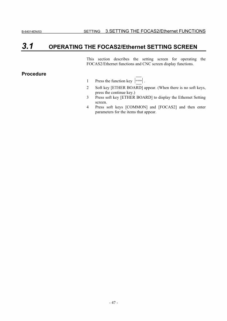
3.1 OPERATING THE FOCAS2/Ethernet SETTING SCREEN This section describes the setting screen for operating the FOCAS2/Ethernet functions and CNC screen display functions.
Procedure 1 Press the function key SYSTEM . 2 Soft key [ETHER BOARD] appear. (When there is no soft keys,
press the continue key.) 3 Press soft key [ETHER BOARD] to display the Ethernet Setting
screen. 4 Press soft keys [COMMON] and [FOCAS2] and then enter
parameters for the items that appear.

3.SETTING THE FOCAS2/Ethernet FUNCTIONS SETTING B-64014EN/03
- 48 -
COMMON screen (BASIC) Press soft key [COMMON] to display the COMMON screen (BASIC).
COMMON screen (BASIC)
Setting item
Item Description IP ADDRESS Specify the IP address of the FAST Ethernet/ FAST
Data Server. (Example of specification format: "192.168.0.100")
SUBNET MASK Specify a mask address for the IP addresses of the network. (Example of specification format: "255.255.255.0")
ROUTER IP ADDRESS
Specify the IP address of the router. Specify this item when the network contains a router. (Example of specification format: "192.168.0.253")
Display item
Item Description MAC ADDRESS FAST Ethernet/ FAST Data Server MAC address
NOTE The second page (detail screen) of the COMMON
screen is to be set when the DNS/DHCP function is used. For details, see Chapter 4, "SETTING THE DNS/DHCP FUNCTION" provided later.

B-64014EN/03 SETTING 3.SETTING THE FOCAS2/Ethernet FUNCTIONS
- 49 -
FOCAS2 screen Press soft key [FOCAS2] to display the FOCAS2 screen.
FOCAS2 screen
Setting item
Item Description PORT NUMBER (TCP)
Specifies the port No. to be used by the FOCAS2/Ethernet functions and CNC screen display functions, within a range of 5001 to 65535.
PORT NUMBER (UDP)
Set 0 when using this item for the FOCAS2/Ethernet functions and CNC screen display functions. Set this port number to communicate with the FANUC CIMPLICITY i CELL.
TIME INTERVAL Set 0 when using this item for the FOCAS2/Ethernet functions and CNC screen display functions. Set this time interval to communicate with the FANUC CIMPLICITY i CELL.
NOTE 1 For connection with the FANUC CIMPLICITY i CELL,
make the above setting according to "FANUC CIMPLICITY i CELL OPERATOR'S MANUAL (B-75074EN)."
2 The unit of TIME INTERVAL is 10 ms. The allowable input range is 10 to 65535. Values less than 100 ms cannot be set.
3 If a smaller value is set in TIME INTERVAL, the communication load can increase to adversely affect the performance of the network. Example) If 100 is set, broadcast data is transmitted at
intervals of 1 second [1000 ms] (=100×10).

3.SETTING THE FOCAS2/Ethernet FUNCTIONS SETTING B-64014EN/03
- 50 -
3.2 RELATED NC PARAMETERS
0020 I/O CHANNEL : Input/output device selection [Data type] Byte [Valid data range] 6 : Selects the FOCAS2/Ethernet as the input/output device. This
parameter is required only for DNC operation, however.
#7 #6 #5 #4 #3 #2 #1 #0
0905 DNCE [Data type] Bit DNCE During DNC operation using the FOCAS2/Ethernet functions, the
termination of DNC operation is: 0: Waited. 1: Not waited. (FOCAS2/HSSB compatible specification)
0924 FOCAS2/Ethernet waiting time setting [Data type] Byte [Valid data range] 0 to 32767
When the FOCAS2/Ethernet and Data Server functions are used simultaneously, this parameter sets the FOCAS2/Ethernet function waiting time in milliseconds. When a value of 0 is set, the functions operate with assuming that 1 millisecond is specified.

B-64014EN/03 SETTING 3.SETTING THE FOCAS2/Ethernet FUNCTIONS
- 51 -
3.3 EXAMPLE OF SETTING THE FOCAS2/Ethernet FUNCTIONS
An example of setting for operating the FOCAS2/Ethernet functions is given below. In this example of setting, one personal computer is connected to two CNCs through a FOCAS2/Ethernet.
100BASE-TX (or 10BASE-T)
CNC 2
CNC 1 PC 1
HUB
CNC 1 CNC 2
IP ADDRESS 192.168.0.100 192.168.0.101
SUBNET MASK 255.255.255.0 255.255.255.0
ROUTER IP ADDRESS None None
PORT NUMBER (TCP) 8193 8193
PORT NUMBER (UDP) 0 0
TIME INTERVAL 0 0
PC 1
IP address 192.168.0.200
Sub-net mask 255.255.255.0
Default gateway None
NC IP address 192.168.0.100 CNC 1
NC TCP port number 8193
NC IP address 192.168.0.101 CNC 2
NC TCP port number 8193
"Microsoft TCP/IP property" of the personal computer (Windows 95/98/NT/2000/XP) is used for setting.
Specify these items with the arguments of the data window library function "cnc_allclibhnd13."
The FOCAS2 setting screen is used for setting.
The common setting screen is used for setting.

4.SETTING THE DNS/DHCP FUNCTION SETTING B-64014EN/03
- 52 -
4 SETTING THE DNS/DHCP FUNCTION This chapter describes the setting of the DNS/DHCP function.
B-64014EN/03 SETTING 4.SETTING THE DNS/DHCP FUNCTION
- 53 -
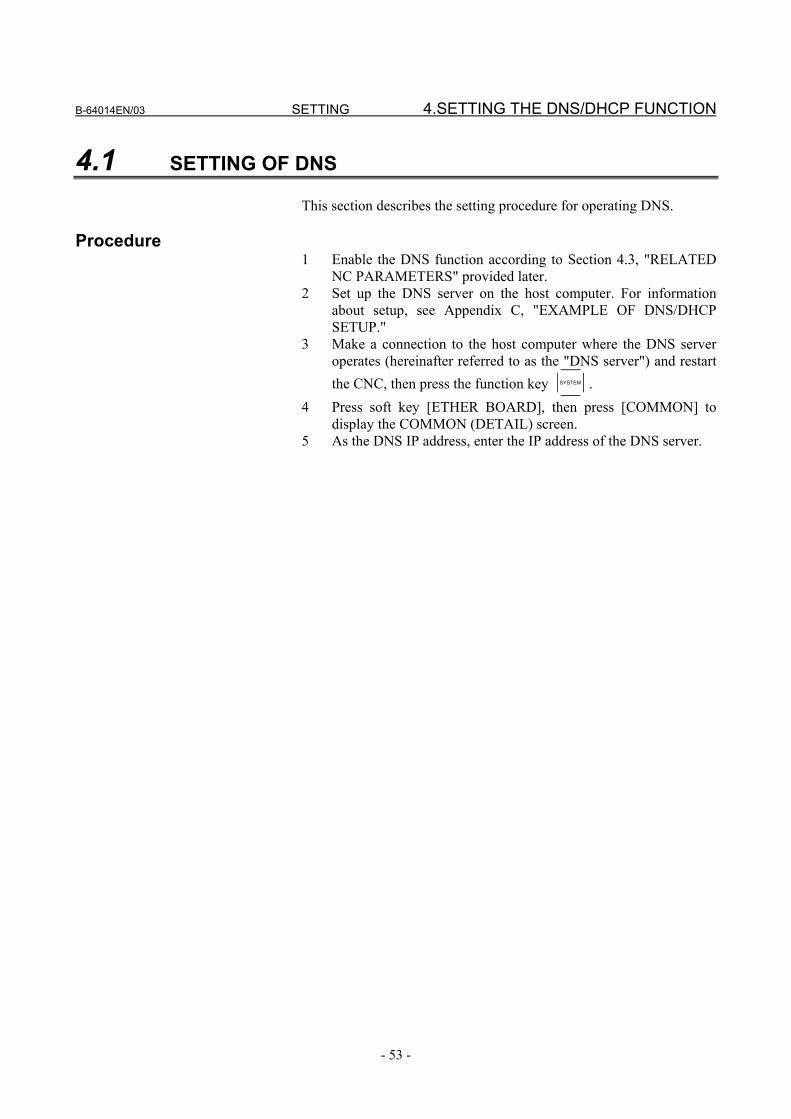
4.1 SETTING OF DNS This section describes the setting procedure for operating DNS.
Procedure 1 Enable the DNS function according to Section 4.3, "RELATED
NC PARAMETERS" provided later. 2 Set up the DNS server on the host computer. For information
about setup, see Appendix C, "EXAMPLE OF DNS/DHCP SETUP."
3 Make a connection to the host computer where the DNS server operates (hereinafter referred to as the "DNS server") and restart the CNC, then press the function key SYSTEM .
4 Press soft key [ETHER BOARD], then press [COMMON] to display the COMMON (DETAIL) screen.
5 As the DNS IP address, enter the IP address of the DNS server.

4.SETTING THE DNS/DHCP FUNCTION SETTING B-64014EN/03
- 54 -
COMMON screen (DETAIL) Press soft key [COMMON] then page keys PAGE
PAGE to display the COMMON (DETAIL) screen. Set the setting items for DNS IP addresses.
COMMON screen (DETAIL)
Setting item
Item Description DNS IP ADDRESS 1, 2
Up to two DNS server IP addresses can be set. The CNC searches for a DNS server in the order from DNS IP address 1 to 2.

B-64014EN/03 SETTING 4.SETTING THE DNS/DHCP FUNCTION
- 55 -
4.2 SETTING OF DHCP This section describes the setting procedure for operating DHCP.
Procedure 1 Enable the DHCP function according to Section 4.3 "RELATED
NC PARAMETERS" provided later. 2 Set up the DHCP server on the host computer. For information
about setup, see Appendix C, "EXAMPLE OF DNS/DHCP SETUP."
3 Make a connection to the host computer where the DHCP server operates (hereinafter referred to as the "DHCP server") and restart the CNC, then press the function key SYSTEM .
4 Press soft key [ETHER BOARD], then press [COMMON] to display the COMMON screen.
5 If the DHCP function of the CNC is enabled and a connection is made successfully with the DHCP server, the following items are set automatically from the DHCP server: • IP ADDRESS • SUBNET MASK • ROUTER IP ADDRESS • DNS IP ADDRESS • DOMAIN
If an attempt to make a connection with the DHCP server fails, "DHCP ERROR" is indicated in each item.
6 Moreover, if the DNS function is enabled at the same time and the DHCP server interacts with the DNS server (the DNS server supports dynamic DNS), enter a desired host name.

4.SETTING THE DNS/DHCP FUNCTION SETTING B-64014EN/03
- 56 -
COMMON screens (BASIC, DETAIL) Press soft key [COMMON] then page keys PAGE
PAGE to display the COMMON screens (BASIC and DETAIL). If a connection is made successfully with the DHCP server and setting data is acquired, the following is displayed:
When a connection with the DHCP server has been made successfully
If no host name is set, the CNC automatically sets a host name in the format "NC-<MAC address>".
Example of host name automatically set

B-64014EN/03 SETTING 4.SETTING THE DNS/DHCP FUNCTION
- 57 -
If an attempt to make a connection with the DHCP server fails, the following is displayed:
When an attempt to make a connection with the DHCP server has failed
Check item
Item Description IP ADDRESS SUBNET MASK ROUTER IP ADDRESSDNS IP ADDRESS 1, 2DOMAIN
If a connection is made successfully with the DHCP server, data acquired from the DHCP server is displayed. If an attempt to make a connection with the DHCP server fails, "DHCP ERROR" is displayed.
Setting item
Item Description HOST NAME Enter a desired CNC host name.
If the DHCP server interacts with the DNS server, this host name is posted to the DNS server. If no host name is set, "NC-<MAC address>" is automatically set.
Example of host name automatically set: NC-00E0E4004CF9
Display item
Item Description MAC ADDRESS FAST Ethernet/FAST Data Server MAC address

4.SETTING THE DNS/DHCP FUNCTION SETTING B-64014EN/03
- 58 -
4.3 RELATED NC PARAMETERS
#7 #6 #5 #4 #3 #2 #1 #0
0904 DHCP DNS D1ET [Data type] Bit DHCP The DHCP function is:
0: Not used. 1: Used.
DNS The DNS function is: 0: Not used. 1: Used.
D1ET When the DHCP function is used: 0: The default parameters for the FOCAS2/Ethernet functions are
set. Port number (TCP) 8193 Port number (UDP) 0 Time interval 0 1: The default parameters for i CELL communication are set. Port number (TCP) 8193 Port number (UDP) 8192 Time interval 50 If any of these parameters has been modified, the power must be turned off then back on for the modification to be become effective.
NOTE Set D1ET to 1 to make a connection with the
FANUC CIMPLICITY i CELL and use the DHCP function and DNS function.

B-64014EN/03 SETTING 4.SETTING THE DNS/DHCP FUNCTION
- 59 -
4.4 EXAMPLE OF SETTING DNS/DHCP
4.4.1 When DNS/DHCP is Used with the Data Server When a connection is made with the FTP server of the host computer (hereinafter referred to as the "FTP server") by using the Data Server function, the IP address of the CNC can be set from the DHCP server by enabling the DHCP function of the CNC. Moreover, by enabling the DNS function of the CNC, an FTP server can be specified with a host name instead of an IP address.
Example of specifying a connection destination with a host name
(FTPServer-1)

4.SETTING THE DNS/DHCP FUNCTION SETTING B-64014EN/03
- 60 -
Setting the DNS server / DHCP server
Operating system It is recommended to use Windows 2000 Server as the operating system.
Setting the DHCP server In the database of the DHCP server, set the following items: • Range of IP addresses to be managed by the DHCP server • Subnet mask to be managed by the DHCP server • IP address for DNS server • Domain The DHCP server enables the function for updating the database of the DNS server. For DHCP server setting, see Section C.1, "EXAMPLE OF SETTING UP DHCP SERVER OF Windows 2000 Server" in Appendix C, "EXAMPLE OF SETTING UP DNS/DHCP."
Setting the DNS server The DNS server allows the DHCP server to update the database of the DNS server. For DNS server setting, see Section C.2, "EXAMPLE OF SETTING UP DNS SERVER OF Windows 2000 Server" in Appendix C, "EXAMPLE OF SETTING UP DNS/DHCP."
Setting the FTP server For FTP server setting, see Appendix D, "EXAMPLE OF FTP SERVER SETUP."
Setting the CNC
Parameter To enable the DNS function, set bit 5 of NC parameter No. 904 to 1. To enable the DHCP function, set bit 6 of NC parameter No. 904 to 1.
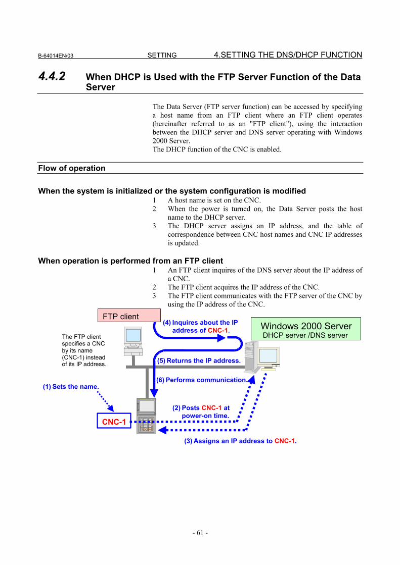
B-64014EN/03 SETTING 4.SETTING THE DNS/DHCP FUNCTION
- 61 -
4.4.2 When DHCP is Used with the FTP Server Function of the Data Server
The Data Server (FTP server function) can be accessed by specifying a host name from an FTP client where an FTP client operates (hereinafter referred to as an "FTP client"), using the interaction between the DHCP server and DNS server operating with Windows 2000 Server. The DHCP function of the CNC is enabled.
Flow of operation
When the system is initialized or the system configuration is modified 1 A host name is set on the CNC. 2 When the power is turned on, the Data Server posts the host
name to the DHCP server. 3 The DHCP server assigns an IP address, and the table of
correspondence between CNC host names and CNC IP addresses is updated.
When operation is performed from an FTP client
1 An FTP client inquires of the DNS server about the IP address of a CNC.
2 The FTP client acquires the IP address of the CNC. 3 The FTP client communicates with the FTP server of the CNC by
using the IP address of the CNC.
CNC-1
(1) Sets the name.
(2) Posts CNC-1 atpower-on time.
(4) Inquires about the IPaddress of CNC-1.
(5) Returns the IP address.
Windows 2000 ServerDHCP server /DNS server
FTP client
(3) Assigns an IP address to CNC-1.
(6) Performs communication.
The FTP clientspecifies a CNCby its name(CNC-1) insteadof its IP address.

4.SETTING THE DNS/DHCP FUNCTION SETTING B-64014EN/03
- 62 -
Setting the DNS server/DHCP server
Operating system It is recommended to use Windows 2000 Server as the operating system. (The DNS server and DHCP server supporting dynamic DNS need to operate.)
Setting the DHCP server In the database of the DHCP server, set the following items: • Range of IP addresses to be managed by the DHCP server • Subnet mask to be managed by the DHCP server • IP address for DNS server • Domain The DHCP server enables the function for updating the database of the DNS server. For DHCP server setting, see Section C.1, "EXAMPLE OF SETTING UP DHCP SERVER OF Windows 2000 Server" in Appendix C, "EXAMPLE OF SETTING UP DNS/DHCP."
Setting the DNS server The DNS server allows the DHCP server to update the database of the DNS server. For DNS server setting, see Section C.2, "EXAMPLE OF SETTING UP DNS SERVER OF Windows 2000 Server" in Appendix C, "EXAMPLE OF SETTING UP DNS/DHCP."
Setting the CNC
Parameter To enable the DHCP function, set bit 6 of NC parameter No. 904 to 1. As a host name, set a desired name. Otherwise, a name automatically set by the FAST Ethernet/FAST Data Server is used.

B-64014EN/03 SETTING 4.SETTING THE DNS/DHCP FUNCTION
- 63 -
4.4.3 When DHCP is Used with the FOCAS2/Ethernet Function Ethernet parameters can be set with no setting performed from the CNC, using the interaction between the DHCP server and DNS server operating with Windows 2000 Server. The DHCP function of the CNC is enabled.
Flow of operation
When the system is initialized or the system configuration is modified 1 A host name is set on the CNC. 2 When the power is turned on, the CNC posts the host name to the
DHCP server. 3 The DHCP server assigns an IP address, and the table of
correspondence between CNC host names and CNC IP addresses is updated.
When FOCAS2/Ethernet application software is executed
1 The user's application inquires of the DNS server about the IP address of a CNC.
2 The user's application acquires the IP address of the CNC. 3 The user's application communicates with the CNC by using the
IP address of the CNC.
CNC-1
(1) Sets the name.
(2) Posts CNC-1 at power-on time.
(4) Inquires about the IP address of CNC-1.
(5) Returns the IP address.
Windows 2000 ServerDHCP server / DNS server
User's application software (FOCAS2/Ethernet)
(3) Assigns an IP address to CNC-1.
(6) Performs communication.
The application software specifies a CNC by its name (CNC-1) instead of its IP address.

4.SETTING THE DNS/DHCP FUNCTION SETTING B-64014EN/03
- 64 -
Setting the DNS server/DHCP server
Operating system It is recommended to use Windows 2000 Server as the operating system. (The DNS server and DHCP server supporting dynamic DNS need to operate.)
Setting the DHCP server In the database of the DHCP server, set the following items: • Range of IP addresses to be managed by the DHCP server • Subnet mask to be managed by the DHCP server • IP address for DNS server • Domain The DHCP server enables the function for updating the database of the DNS server. For DHCP server setting, see Section C.1, "EXAMPLE OF SETTING UP DHCP SERVER OF Windows 2000 Server" in Appendix C, "EXAMPLE OF SETTING UP DNS/DHCP."
Setting the DNS server The DNS server allows the DHCP server to update the database of the DNS server. For DNS server setting, see Section C.2, "EXAMPLE OF SETTING UP DNS SERVER OF Windows 2000 Server" in Appendix C, "EXAMPLE OF SETTING UP DNS/DHCP."
Setting the CNC
Parameter To enable the DHCP function, set bit 6 of NC parameter No. 904 to 1. As a host name, set a desired name. Otherwise, a name automatically set by the FAST Ethernet/FAST Data Server is used. When the DHCP function is enabled, the FOCAS2/Ethernet-related parameters are automatically set if bit 3 of NC parameter No. 904 is set to 0. If bit 3 of NC parameter No. 904 is set to 1, the parameters for i CELL communication are automatically set.

B-64014EN/03 SETTING 5.SETTING THE MACHINE REMOTE DIAGNOSIS FUNCTIONS
- 65 -
5 SETTING THE MACHINE REMOTE DIAGNOSIS FUNCTIONS
This chapter describes the setting of parameters for the machine remote diagnosis functions. For explanation of the entire machine remote diagnosis functions, refer to "MACHINE REMOTE DIAGNOSIS PACKAGE OPERATOR'S MANUAL (B-63734EN)."

5.SETTING THE MACHINE REMOTE DIAGNOSIS FUNCTIONS SETTING B-64014EN/03
- 66 -
5.1 OPERATING THE MACHINE REMOTE DIAGNOSIS SETTING SCREEN
This section describes the setting screen for operating the machine remote diagnosis functions.
Procedure 1 Press the function key SYSTEM . 2 Soft key [ETHER BOARD] appear. (When there is no soft keys,
press the continue key.) 3 Press soft key [ETHER BOARD] to display the Ethernet Setting
screen. 4 Press soft keys [COMMON], [FOCAS2], and [REMOTE DIAG]
and then enter parameters for the items that appear.

B-64014EN/03 SETTING 5.SETTING THE MACHINE REMOTE DIAGNOSIS FUNCTIONS
- 67 -
COMMON screen (BASIC) Press soft key [COMMON] to display the COMMON screen (BASIC).
COMMON screen (BASIC)
Setting item Item Description
IP ADDRESS Specify the IP address of the FAST Ethernet / FAST Data Server. (Example of specification format: "192.168.0.100")
SUBNET MASK Specify a mask address for the IP addresses of the network. (Example of specification format: "255.255.255.0")
ROUTER IP ADDRESS
Specify the IP address of the router. Specify this item when the network contains a router. (Example of specification format: "192.168.0.253")
Display item
Item Description MAC ADDRESS FAST Ethernet / FAST Data Server MAC address
NOTE The second page (detail screen) of the COMMON
screen is to be set when the DNS/DHCP function is used. For details, see Chapter 4 "SETTING THE DNS/DHCP FUNCTION".

5.SETTING THE MACHINE REMOTE DIAGNOSIS FUNCTIONS SETTING B-64014EN/03
- 68 -
COMMON screen (DETAIL) Press soft key [COMMON] then page keys PAGE
PAGE to display the COMMON (DETAIL) screen. Set the setting items for DNS IP addresses.
COMMON screen (DETAIL)
Setting item
Item Description DNS IP ADDRESS 1, 2
Up to two DNS server IP addresses can be set. The CNC searches for a DNS server in the order from DNS IP address 1 to 2.

B-64014EN/03 SETTING 5.SETTING THE MACHINE REMOTE DIAGNOSIS FUNCTIONS
- 69 -
FOCAS2 screen Press soft key [FOCAS2] to display the FOCAS2 screen.
FOCAS2 screen
Setting item
Item Description PORT NUMBER (TCP)
Specifies the port No. to be used by the machine remote diagnosis functions (FOCAS2/Ethernet functions), within a range of 5001 to 65535.
PORT NUMBER (UDP)
Set 0 when using this item for the machine remote diagnosis functions (FOCAS2/Ethernet functions). Set this port number to communicate with the FANUC CIMPLICITY i CELL.
TIME INTERVAL Set 0 when using this item for the machine remote diagnosis functions (FOCAS2/Ethernet functions). Set this time interval to communicate with the FANUC CIMPLICITY i CELL.
NOTE 1 For connection with the FANUC CIMPLICITY i CELL,
make the above setting according to "FANUC CIMPLICITY i CELL OPERATOR'S MANUAL (B-75074EN)."
2 The unit of TIME INTERVAL is 10 ms. The allowable input range is 10 to 65535. Values less than 100 ms cannot be set.
3 If a smaller value is set in TIME INTERVAL, the communication load can increase to adversely affect the performance of the network. Example) If 100 is set, broadcast data is transmitted at
intervals of 1 second [1000 ms] (=100×10).

5.SETTING THE MACHINE REMOTE DIAGNOSIS FUNCTIONS SETTING B-64014EN/03
- 70 -
MACHINE REMOTE DIAG screen (COMMON) Press soft key [REMOTE DIAG] to display the MACHINE REMOTE DIAG screen (COMMON).
Machine remote diagnosis screen (BASIC)
Setting item
Item Description MTB ID This information is required by the machine remote
diagnosis package to confirm that the diagnosis request is issued from a machine manufactured by the machine tool builder. The MTB identification information on the diagnosis accepting server of the machine remote diagnosis package can be set to accept diagnosis requests only from the machines manufactured by the machine tool builder. (Example of specification format: "FANUC")
MACHINE ID Information required by the machine remote diagnosis package to identify the machine under diagnosis (Example of specification format: "217xxx-1011xxxxx")

B-64014EN/03 SETTING 5.SETTING THE MACHINE REMOTE DIAGNOSIS FUNCTIONS
- 71 -
MACHINE REMOTE DIAG screen (INQUIRY1, INQUIRY2, INQUIRY3) Press soft key [REMOTE DIAG] to display the MACHINE REMOTE DIAG screen. By using page keys PAGE
PAGE , the three host computers at inquiry destinations 1, 2, and 3 can be set.
MACHINE REMOTE DIAG screens (INQUIRY1):
Screen when the DNS function is disabled (left) and screen when the function is enabled (right)
Setting item Item Description
HOST NAME Specify the IP address of the host computer (machine remote diagnosis accepting server) when the DNS function is disabled. (Example of specification format: "200.201.202.203") Specify the host name of the host computer (machine remote diagnosis accepting server) when the DNS function is enabled. (You can specify up to 63 characters.) (Example of specification format: "RMTDIAG.FANUC.CO.JP")
PORT NUMBER Specify a port number. Usually, specify "8194" because the machine remote diagnosis functions are used.
INQUIRY NAME Specify information for identifying the host computer (machine remote diagnosis accepting server). (You can specify up to 63 characters.) (Example of specification format: "FANUC LTD.")

5.SETTING THE MACHINE REMOTE DIAGNOSIS FUNCTIONS SETTING B-64014EN/03
- 72 -
5.2 RELATED NC PARAMETERS
0024 Setting of communication with the PMC ladder development tool [Data type] Byte [Valid data range] 10: The high-speed interface (Ethernet) is used for PMC online
editing.
#7 #6 #5 #4 #3 #2 #1 #0
0904 DNS [Data type] Bit DNS The DNS function is:
0: Not used. 1: Used. If this parameter has been modified, the power must be turned off then back on for the modification to be become effective.
NOTE To use the DNS function, set DNS IP ADDRESS 1
and DNS IP ADDRESS 2 on the COMMON (DETAIL) screen.
#7 #6 #5 #4 #3 #2 #1 #0
8706 MRD [Data type] Bit MRD Type of communication device to be used by the machine remote
diagnosis functions: 0: The FAST Ethernet/FAST Data Server is not used. 1: The FAST Ethernet/FAST Data Server is used. If this parameter has been modified, the power must be turned off then back on for the modification to be become effective.

B-64014EN/03 SETTING 5.SETTING THE MACHINE REMOTE DIAGNOSIS FUNCTIONS
- 73 -
5.3 CONTROLLING THE MACHINE REMOTE DIAGNOSIS FUNCTIONS FROM THE PMC
You can use signals from the PMC to control the start and forced termination of the machine remote diagnosis functions and post the status of the machine remote diagnosis functions and error numbers to the PMC ladder.
5.3.1 Signals
No. #7 #6 #5 #4 #3 #2 #1 #0
G0141 DIAREQ DIASTP INQU2 INQU1 INQU0 DIAREQ <G0141#5> [Name] Signal to request machine remote diagnosis [Classification] Input signal [Function] Requests the start of machine remote diagnosis. [Operation] When this signal is set to "1", it requests the start of machine remote
diagnosis to the inquiry destination according to the signals indicating the number of the inquiry destination (INQU0 to INQU2). When the acceptance completion signal (RMTEND) or acceptance reject signal (RMTCAN) is set to "1", this signal is set to "0".
DIASTP <G0141#4> [Name] Signal to request machine remote diagnosis cancellation [Classification] Input signal [Function] Requests the forced termination of machine remote diagnosis. [Operation] When this signal is set to "1", it requests forced termination to the
machine remote diagnosis accepting server. When the completion signal for machine remote signal cancel acceptance (RMTCLS) is set to "1", this signal is set to "0".
INQU2 <G0141#2> INQU1 <G0141#1> INQU0 <G0141#0> [Name] Inquiry number select signals [Classification] Input signal [Function] Inquiry destination for which to start machine remote diagnosis [Operation] Select an item from the table below as an inquiry destination for
which to start machine remote signal.
INQU2 INQU1 INQU0 Status 0 0 0 No selection 0 0 1 Inquiry destination 1 0 1 0 Inquiry destination 2 0 1 1 Inquiry destination 3

5.SETTING THE MACHINE REMOTE DIAGNOSIS FUNCTIONS SETTING B-64014EN/03
- 74 -
No. #7 #6 #5 #4 #3 #2 #1 #0
F0082 RMTCLS RMTCLS <F0082#3> [Name] Completion signal for machine remote diagnosis cancel acceptance [Classification] Output signal [Function] Notifies that a request to cancel machine remote diagnosis has been
accepted. [Output condition] When machine remote diagnosis is canceled after the signal to request
machine remote diagnosis cancellation (DIASTP) is set to "1", this signal is set to "1". When the signal to request machine remote diagnosis cancellation (DIASTP) is set to "0", this signal is set to "0".
No. #7 #6 #5 #4 #3 #2 #1 #0
F0083 RMTCAN RMTEND DIAST5 DIAST4 DIAST3 DIAST2 DIAST1 DIAST0 RMTCAN <F0083#7> [Name] Reject signal for machine remote diagnosis acceptance [Classification] Output signal [Function] Notifies that a machine remote diagnosis request has been rejected. [Output condition] When the signal to request machine remote diagnosis (DIAREQ) is set
to "1", a request to start machine remote diagnosis is issued to the machine remote diagnosis accepting server. When the server rejects the request, this signal is set to "1". When the signal to request machine remote diagnosis (DIAREQ) is set to "0", this signal is set to "0".
RMTEND <F0083#6> [Name] Completion signal for machine remote diagnosis acceptance [Classification] Output signal [Function] Notifies that a machine remote diagnosis request has been accepted by
the machine remote diagnosis accepting server. [Output condition] When the signal to request machine remote diagnosis (DIAREQ) is set
to "1", a request to start machine remote diagnosis is issued to the machine remote diagnosis accepting server. When the server accepts the request, this signal is set to "1". When the signal to request machine remote diagnosis (DIAREQ) is set to "0", this signal is set to "0".

B-64014EN/03 SETTING 5.SETTING THE MACHINE REMOTE DIAGNOSIS FUNCTIONS
- 75 -
DIAST5 <F0083#5> DIAST4 <F0083#4> DIAST3 <F0083#3> DIAST2 <F0083#2> DIAST1 <F0083#1> DIAST0 <F0083#0> [Name] Notification signals for the machine remote diagnosis status [Classification] Output signal [Function] Report the status of machine remote diagnosis. [Output condition] The status of machine remote diagnosis is reported as listed in the
following table. DIAST5 DIAST4 DIAST3 DIAST2 DIAST1 DIAST0 Description
0 0 0 0 0 0 No status 0 0 0 0 0 1 OPEN 0 0 0 0 1 0 OPENING 0 0 0 0 1 1 ACCEPTED 0 0 0 1 0 0 REFUSED 0 0 0 1 0 1 DIAGNOSING 0 0 0 1 1 0 DIAGNOSING 0 0 0 1 1 1 CLOSE 0 0 1 0 0 0 FORCE CLOSING0 0 1 0 0 1 ERROR
No. #7 #6 #5 #4 #3 #2 #1 #0
F0088 DIAER7 DIAER6 DIAER5 DIAER4 DIAER3 DIAER2 DIAER1 DIAER0
DIAER7 <F0088#7> DIAER6 <F0088#6> DIAER5 <F0088#5> DIAER4 <F0088#4> DIAER3 <F0088#3> DIAER2 <F0088#2> DIAER1 <F0088#1> DIAER0 <F0088#0> [Name] Notification signals for a machine remote diagnosis error number [Classification] Output signal [Function] Report an error number of machine remote diagnosis. [Output condition] These signals indicate an error number of machine remote diagnosis.
The error number is 0 to 255 in binary format.

5.SETTING THE MACHINE REMOTE DIAGNOSIS FUNCTIONS SETTING B-64014EN/03
- 76 -
5.3.2 Signal Timing Charts This section describes control of the start and forced termination of machine remote diagnosis according to the signals from the PMC using timing charts.
5.3.2.1 When the start of machine remote diagnosis is accepted
INQU0 (G141#0)
INQU1 (G141#1)
INQU2 (G141#2)
DIAREQ (G141#5)
RMTEND (F083#6)
<1>
<2>
<3>
<4>
The start of machine remote diagnosis is accepted.
<5>
<1> Before the signal to request machine remote diagnosis (DIAREQ) is set to "1", an inquiry destination for which to start the remote diagnosis functions is selected using the inquiry destination number signals (INQU0, INQU1, and INQU2). In this example, "inquiry destination 3" is selected by setting INQU0 = 1, INQU1 = 1, and INQU2 = 0.
<2> The signal to request machine remote diagnosis (DIAREQ) is set to "1".
<3> When the machine remote diagnosis package accepts the request to start diagnosis, the completion signal for machine remote diagnosis acceptance (RMTEND) is set to "1".
<4> When the completion signal for machine remote diagnosis acceptance (RMTEND) is set to "1", the signal to request machine remote diagnosis (DIAREQ) is set to "0".
<5> When the signal to request machine remote diagnosis (DIAREQ) is set to "0", the completion signal for machine remote diagnosis acceptance (RMTEND) is set to "0".

B-64014EN/03 SETTING 5.SETTING THE MACHINE REMOTE DIAGNOSIS FUNCTIONS
- 77 -
5.3.2.2 When the start of machine remote diagnosis is rejected
INQU0 (G141#0)
INQU1 (G141#1)
INQU2 (G141#2)
DIAREQ (G141#5)
RMTCAN (F083#7)
<1>
<2>
<3>
<4>
The start of machine remote diagnosis is rejected.
<5>
<1> Before the signal to request machine remote diagnosis
(DIAREQ) is set to "1", an inquiry destination for which to start the remote diagnosis functions is selected using the inquiry destination number signals (INQU0, INQU1, and INQU2). In this example, "inquiry destination 3" is selected by setting INQU0 = 1, INQU1 = 1, and INQU2 = 0.
<2> The signal to request machine remote diagnosis (DIAREQ) is set to "1".
<3> When the machine remote diagnosis package rejects the request to start diagnosis, the reject signal for machine remote diagnosis acceptance (RMTCAN) is set to "1".
<4> When the reject signal for machine remote diagnosis acceptance (RMTCAN) is set to "1", the signal to request machine remote diagnosis (DIAREQ) is set to "0".
<5> When the signal to request machine remote diagnosis (DIAREQ) is set to "0", the reject signal for machine remote diagnosis acceptance (RMTCAN) is set to "0".

5.SETTING THE MACHINE REMOTE DIAGNOSIS FUNCTIONS SETTING B-64014EN/03
- 78 -
5.3.2.3 When machine remote diagnosis is forcibly terminated
DIASTP (G141#4)
RMTCLS (F082#3) <1>
<2>
<3>
Machine remote diagnosis is forcibly terminated.
<1> When the signal to request machine remote diagnosis
cancellation (DIASTP) is set to "1", the completion signal for machine remote diagnosis cancel acceptance (RMTCLS) is set to "1".
<2> When the completion signal for machine remote diagnosis cancel acceptance (RMTCLS) is set to "1", the signal to request machine remote diagnosis cancellation (DIASTP) is set to "0".
<3> When the signal to request machine remote diagnosis cancellation (DIASTP) is set to "0", the completion signal for machine remote diagnosis cancel acceptance (RMTCLS) is set to "0" and the machine remote diagnosis functions are forcibly terminated.

B-64014EN/03 SETTING 5.SETTING THE MACHINE REMOTE DIAGNOSIS FUNCTIONS
- 79 -
5.4 EXAMPLE OF SETTING THE MACHINE REMOTE DIAGNOSIS FUNCTIONS
An example of setting for operating the machine remote diagnosis functions is given below. In this example of setting, one personal computer functions as the machine remote diagnosis accepting server and machine remote diagnosis client and is connected to one CNC.
100BASE-TX (or 10BASE-T)
CNC 1 PC 1
HUB
CNC 1 IP ADDRESS 192.168.0.100 SUBNET MASK 255.255.255.0 ROUTER IP ADDRESS None PORT NUMBER (TCP) 8193 PORT NUMBER (UDP) 0 TIME INTERVAL 0 MTB ID FANUC MACHINE ID 217XXX-101XXXXXINQUIRY 1 : HOST NAME 192.168.0.200 INQUIRY 1 : PORT NUMBER 8194
PC 1
IP address 192.168.0.200 Sub-net mask 255.255.255.0 Default gateway None Accepting server : PORT NUMBER 8194 Proxy server : PORT NUMBER 8193
MTB ID Accepts all diagnosis
requests.
The FOCAS2 setting screen is used for setting.
The common setting screen is used for setting.
The machine remote diagnosis screen is used for setting.
"Diagnosis accepting server setting" of the machine remote diagnosis package is used for setting.
"Microsoft TCP/IP property" of the personal computer (Windows 95/98/NT/2000/XP) is used for setting.

6.ERROR MESSAGES DISPLAYED DURING PARAMETER SETTING SETTING B-64014EN/03
- 80 -
6 ERROR MESSAGES DISPLAYED DURING PARAMETER SETTING
This chapter explains the error messages that are issued when FAST Ethernet/FAST Data Server parameters are set.
Messages Meaning and action to be taken Communication Software is not found Check whether the communication software is installed. Ethernet board is not found Check whether the Ethernet board is installed. Software Version Error The communication software version is illegal.
Check the software version. DATA IS OUT OF RANGE A numeric parameter value is beyond the range. Wrong Character(s) An illegal character is used in a character parameter. Format Error Input data such as an IP address has an illegal input format. too many figures A value input in a numeric parameter consists of too many digits. Data was rejected A parameter error is found.
Confirm the setting conditions described in the relevant manual. Reading from SRAM failed SRAM may have been destroyed. Writing into SRAM failed SRAM may have been destroyed. DHCP is available When the DHCP function is enabled, it is impossible to input parameters
manually from the setting screen. To input parameters manually, disable the DHCP function.
Error(xxxx) Other errors. Check the parameter settings and contact FANUC.

IV. OPERATION


B-64014EN/03 OPERATION 1.OPERATING THE DATA SERVER FUNCTIONS
- 83 -
1 OPERATING THE DATA SERVER FUNCTIONS
This chapter describes how to operate the Data Server functions. On the PROGRAM FOLDER screen, files on the CNC memory, memory card, host computer connected via the embedded Ethernet, memory card built into the FAST Data Server, or host computer connected via the FAST Data Server can be handled by selecting a device.
CNC memory
Memory card
FAST Data Server
Memory card
File list
File list
Via embedded Ethernet
Via FAST Data Server PROGRAM FOLDER screen
Series 30i/31i/32i-A
In this manual, the method of handling files on the memory card built into the FAST Data Server and on the host computer connected via the FAST Data Server is described.

1.OPERATING THE DATA SERVER FUNCTIONS OPERATION B-64014EN/03
- 84 -
1.1 DEVICE CHANGE ON THE PROGRAM FOLDER SCREEN
Procedure 1 Press the function key PROG . 2 Press soft key [FOLDER] to display the PROGRAM FOLDER
screen. (When there is no soft keys, press the continue key.)
PROGRAM FOLDER screen
3 Press soft key [(OPRT)] then soft key [DEVICE CHANGE] to
display the soft keys for selectable devices.
4 When you press soft key [DTSVR], the information displayed on
the PROGRAM FOLDER screen is changed to the contents (DATA SERVER FILE LIST screen) of the memory card built into the FAST Data Server to enable file operation.
5 When you press soft key [DTSVR HOST], the information displayed on the PROGRAM FOLDER screen is changed to the contents (DATA SERVER HOST FILE LIST screen) of the hard disk of the host computer to enable file operation.

B-64014EN/03 OPERATION 1.OPERATING THE DATA SERVER FUNCTIONS
- 85 -
1.2 OPERATING THE DATA SERVER FILE LIST SCREEN If [DTSVR] is selected to change the device on the PROGRAM FOLDER screen, the contents (DATA SERVER FILE LIST screen) of the memory card built into the FAST Data Server are displayed to enable file operation. The information displayed on the DATA SERVER FILE LIST screen partly changes, depending on the setting of bit 1 (PDM) of NC parameter No. 3233. When bit 1 (PDM) of parameter No. 3233 is set to 0, an M198 operation folder and DNC operation file can be set. When bit 1 (PDM) of parameter No. 3233 is set to 1, foreground/background folders can be set.

1.OPERATING THE DATA SERVER FUNCTIONS OPERATION B-64014EN/03
- 86 -
DATA SERVER FILE LIST screen / When PDM=0 (No.3233#1=0)
DATA SERVER FILE LIST screen / When PDM=1 (No.3233#1=1)

B-64014EN/03 OPERATION 1.OPERATING THE DATA SERVER FUNCTIONS
- 87 -
Display item
M198 OPE FOLDER Displays a folder (directory) for M198-based subprogram calling. This item is displayed when bit 1 (PDM) of parameter No. 3233 is set to 0.
DNC OPE FILE Displays a file name used when DNC operation is performed. This item is displayed when bit 1 (PDM) of parameter No. 3233 is set to 0.
FOREGROUND FOLDER / BACKGROUND FOLDER Displays foreground/background folders (directories). This item is displayed when bit 1 (PDM) of parameter No. 3233 is set to 1.
CONNECT HOST Displays the work folder and the number of the host currently connected.
USED PAGE / FREE PAGE Displays the size used of the memory card built into the FAST Data Server and the size that is free.
USED FILES / FREE FILES Displays the total number of folders (files) in use of the Data Server and the number of remaining free folders (files).
DEVICE Displays the current device. If the memory card built into the FAST Data Server is selected, "DATA_SV" is indicated.
CURRENT FOLDER Displays the current work folder.
File list Displays information about the files and folders in the current work folder.

1.OPERATING THE DATA SERVER FUNCTIONS OPERATION B-64014EN/03
- 88 -
Operation list
DEVICE CHANGE Enables a device for display on the PROGRAM FOLDER screen. When selecting the memory card built into the FAST Data Server, press soft key [DTSVR].
DNC SET Specifies a file for DNC operation. This soft key can be used when bit 1 (PDM) of parameter No. 3233 is set to 0.
M198 SET Specifies a folder for M198-based subprogram calling. This soft key can be used when bit 1 (PDM) of parameter No. 3233 is set to 0.
FORE CHANGE / BACK CHNAGE Specifies a foreground/background folder. These soft keys can be used when bit 1 (PDM) of parameter No. 3233 is set to 1.
MAIN PROGRM Selects a file as a main program.
DETAIL OFF / DETAIL ON Switches the file list information to overall display or detail display.
CREATE FOLDER Creates a sub-folder under the current work folder.
DELETE Deletes a file or folder.
RENAME Renames a file or folder.
SELECT START Selects multiple files.
COPY Copies a file within the Data Server.
SEARCH Searches for a file in the current work folder.
PUT Transfers a file from the Data Server to the host computer.
MPUT Transfers multiple files from the Data Server to the host computer.

B-64014EN/03 OPERATION 1.OPERATING THE DATA SERVER FUNCTIONS
- 89 -
LIST-PUT Transfers multiple files from the Data Server to the host computer according to a list file.
LIST-DELETE Deletes multiple files from the Data Server according to a list file.
REFRESH Updates the display information of the PROGRAM FOLDER screen.
NOTE The operations of soft keys [CREATE FOLDER],
[DELETE], [RENAME], [COPY], and [LIST-DELETE] are the target operations of the memory protection key.
This means that when the memory protection key is enabled, these operations result in a "WRITE PROTECT" error and cannot be performed.
For information about the memory protection key, refer to the CONNECTION MANUAL (FUNCTION) (B-63943EN-1) of the CNC.

1.OPERATING THE DATA SERVER FUNCTIONS OPERATION B-64014EN/03
- 90 -
1.2.1 Displaying and Operating the File List
REFRESH, DETAIL OFF, DETAIL ON The contents of the file list can be updated and displayed. 1 Press soft key [REFRESH] to update the contents of the file list. 2 Press soft key [DETAIL OFF] to display a file name, size, and
date. 3 Press soft key [DETAIL ON] to display a file list with file
attributes and comments. A comment statement immediately following the O number of a file is displayed. When there is no comment statement, the contents starting with the beginning of the file are displayed.
NOTE 1 For a file selected as a main program and a file
being used for memory operation, no comment is displayed in detail display mode.
2 The file attribute of a binary file is displayed as "R/B" to the right of the comment.
MOVE FOLDER
A folder can be moved. 1 By using cursor keys , select a folder to be moved.
2 Press the MDI key INPUT .
CREATE FOLDER A new folder can be created. 1 Move to a new folder to be created. 2 Enter a desired folder name. 3 Press soft key [CREATE FOLDER].
NOTE 1 Up to six levels of folders can be created. 2 No duplicate folder name is allowed within the
same folder. 3 Each time a folder is created, the number of
programs that can be registered decreases by one. 4 No folder may be able to be created, depending on
the status such as operation state or protection state.

B-64014EN/03 OPERATION 1.OPERATING THE DATA SERVER FUNCTIONS
- 91 -
DELETE A file or folder can be deleted. 1 By using cursor keys , select a file or folder to be
deleted. 2 Press soft key [DELETE].
- Press soft key [EXEC] for execution. - Press soft key [CANCEL] for cancellation.
NOTE 1 The initial folder cannot be deleted. 2 A folder can be deleted only when the folder is
empty. (An empty folder means a folder that does not contain any folder and file.)
3 If a folder contains a folder or file that has the edit/display prohibition attribute set, the folder appears to be empty but is not actually empty. So, the folder cannot be deleted.
4 Files or folders may not be able to be deleted, depending on the status such as operation state or protection state.
DELETE (multiple files)
Multiple files can be deleted at a time. 1 Press soft key [SELECT START]. 2 By using cursor keys , select a file to be deleted. 3 Press soft key [SELECT]. A selected file is displayed in reverse video. Repeat steps 2 and 3 for files to be deleted. 4 Press soft key [DELETE].
• Press soft key [EXEC] for execution. • Press soft key [CANCEL] for cancellation.
NOTE 1 If a folder contains a file that has the edit/display
prohibition attribute set, the folder appears to be empty but is not actually empty. So, the folder cannot be deleted.
2 Files may not be able to be deleted, depending on the status such as operation state or protection state.
3 Up to 10 files can be selected at a time.

1.OPERATING THE DATA SERVER FUNCTIONS OPERATION B-64014EN/03
- 92 -
RENAME A file or folder can be renamed. 1 By using cursor keys , select a file or folder to be
renamed. 2 Key a new file name or folder name. 3 Press soft key [RENAME].
NOTE 1 The initial folder cannot be renamed. 2 No duplicate folder name is allowed within the
same folder. 3 Files and folders may not be able to be renamed,
depending on the status such as operation state or protection state.
COPY
In the Data Server, a file can be copied within the same folder. 1 Place the CNC in the EDIT mode. 2 By using cursor keys , select a copy source file. 3 Key the name of a copy destination file. 4 Press soft key [COPY].
NOTE 1 Copy operation is impossible if the same file is
specified as a copy source file and copy destination file.
2 Files may not be able to be copied, depending on the status such as operation state or protection state.

B-64014EN/03 OPERATION 1.OPERATING THE DATA SERVER FUNCTIONS
- 93 -
COPY (multiple files) In the Data Server, multiple files can be copied. 1 Place the CNC in the EDIT mode. 2 Press soft key [SELECT START]. 3 By using cursor keys , select a copy source file. 4 Press soft key [SELECT]. A selected file is displayed in reverse video. Repeat steps 2 and 3 for files to be copied. 5 Press soft key [SELECT END]. 6 Move to a copy destination folder. 7 Press soft key [COPY].
NOTE 1 Copy operation is impossible if the same folder is
specified as a copy source folder and copy destination folder.
2 Files may not be able to be copied, depending on the status such as operation state or protection state.
3 Up to 10 files can be selected at a time.
SEARCH In the current work folder, a file can be found. 1 Enter a desired file name. 2 Press soft key [SEARCH].
LIST-DELETE By using a list file, multiple files in the Data Server can be deleted. 1 By using cursor keys , select a list file. 2 Press soft key [LIST-DELETE].
• Press soft key [EXEC] for execution. • Press soft key [CANCEL] for cancellation.
When execution is selected, the files in the Data Server are deleted according to the list file.
NOTE Files cannot sometimes be deleted depending on
the operation status and protection status.

1.OPERATING THE DATA SERVER FUNCTIONS OPERATION B-64014EN/03
- 94 -
1.2.2 File Transfer Operation Files can be transferred from the Data Server to the host computer.
NOTE If an error occurs, check the cause of the error
according to the Item, “ETHERNET LOG screen” in Section 2.1, ”ETHERNET LOG” in Part VI, “MAINTENANCE.”
PUT
A file can be transferred from the Data Server to the host computer. 1 By using cursor keys , select a file to be transferred. 2 Press soft key [PUT].
• Press soft key [EXEC] for execution. • Press soft key [CANCEL] for cancellation.
3 When a file is to be transferred to the host computer under a different file name, enter the desired transfer destination file name before pressing soft key [PUT].
MPUT
Multiple files can be transferred from the Data Server to the host computer. 1 Enter the names of files to be transferred. File names can be
specified using wildcards (*, ?). 2 Press soft key [MPUT].
• Press soft key [EXEC] for execution. • Press soft key [CANCEL] for cancellation.
LIST-PUT
Multiple files can be transferred from the Data Server to the host computer according to a list file. 1 By using cursor keys , select a list file. 2 Press soft key [LIST-PUT].
• Press soft key [EXEC] for execution. • Press soft key [CANCEL] for cancellation.
When execution is selected, the files are transferred from the
Data Server to the host computer according to the list file.

B-64014EN/03 OPERATION 1.OPERATING THE DATA SERVER FUNCTIONS
- 95 -
1.2.3 Preparations for File Operation and Editing
MAIN PROGRM A selected file can be registered as a main program. 1 Select the EDIT mode or MEM mode. 2 By using cursor keys , select a file to be registered as a
main program. 3 Press soft key [MAIN PROGRM]. A registered main program can be executed in memory operation or edited.
NOTE 1 No file may be able to be selected, depending on
the status such as operation state or protection state.
2 Only a text file can be selected as a main program. 3 For a file selected as a main program and a file
being used for memory operation, no comment is displayed in detail display mode.
4 For a file selected as a main program, other file operations are disabled.
5 For memory operation and editing, refer to the USER'S MANUAL of the CNC.
M198 SET
A folder for M198-based subprogram calling can be specified. 1 Move to the folder containing a file to be called by M198-based
subprogram calling. 2 Press soft key [M198 SET].
NOTE 1 No file may be able to be selected, depending on
the status such as operation state or protection state.
2 This setting is valid when the operating mode of the Data Server is the storage mode.

1.OPERATING THE DATA SERVER FUNCTIONS OPERATION B-64014EN/03
- 96 -
DNC SET A file used for DNC operation can be selected. 1 Move to the folder containing a file to be used for DNC
operation. 2 By using cursor keys , select a file to be used for DNC
operation. 3 Press soft key [DNC SET].
NOTE 1 No file may be able to be selected, depending on
the status such as operation state or protection state.
2 This setting is valid when the operating mode of the Data Server is the storage mode.
FORE CHANGE / BACK CHANGE
A foreground/background file can be specified. 1 Move to the folder containing a foreground/background file. 2 Press soft key [FORE CHANGE] or [BACK CHANGE].

B-64014EN/03 OPERATION 1.OPERATING THE DATA SERVER FUNCTIONS
- 97 -
1.3 OPERATING THE DATA SERVER HOST FILE LIST SCREEN
Host computer files can be operated on the DATA SERVER HOST FILE LIST screen.
DATA SERVER HOST FILE LIST screen
NOTE A file name containing kanji, hiragana, or katakana
characters is not displayed correctly.
Display item
M198 OPE FOLDER Displays a folder (directory) for M198-based subprogram calling.
DNC OPE FILE Displays a file name used when DNC operation is performed.
DT SERVER FOLDER Displays the work folder (directory) of the Data Server (memory card).
CONNECT HOST Displays the number of the host computer currently connected.
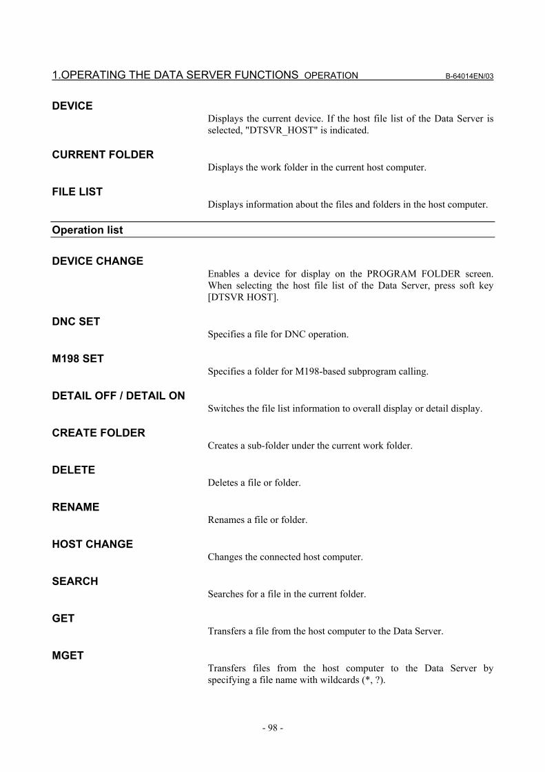
1.OPERATING THE DATA SERVER FUNCTIONS OPERATION B-64014EN/03
- 98 -
DEVICE Displays the current device. If the host file list of the Data Server is selected, "DTSVR_HOST" is indicated.
CURRENT FOLDER Displays the work folder in the current host computer.
FILE LIST Displays information about the files and folders in the host computer.
Operation list
DEVICE CHANGE Enables a device for display on the PROGRAM FOLDER screen. When selecting the host file list of the Data Server, press soft key [DTSVR HOST].
DNC SET Specifies a file for DNC operation.
M198 SET Specifies a folder for M198-based subprogram calling.
DETAIL OFF / DETAIL ON Switches the file list information to overall display or detail display.
CREATE FOLDER Creates a sub-folder under the current work folder.
DELETE Deletes a file or folder.
RENAME Renames a file or folder.
HOST CHANGE Changes the connected host computer.
SEARCH Searches for a file in the current folder.
GET Transfers a file from the host computer to the Data Server.
MGET Transfers files from the host computer to the Data Server by specifying a file name with wildcards (*, ?).

B-64014EN/03 OPERATION 1.OPERATING THE DATA SERVER FUNCTIONS
- 99 -
BGET Transfers a file from the host computer to the Data Server in binary format. Use this soft key to transfer a binary-format NC program or data other than an NC program such as NC parameter or tool data.
LIST-GET Transfers multiple files from the host computer to the Data Server according to a list file.
REFRESH Updates the information displayed on the DATA SERVER HOST FILE LIST screen.
NOTE The operations of soft keys [GET], [MGET],
[BGET], and [LIST-GET] are the target operations of the memory protection key.
This means that when the memory protection key is enabled, these operations result in a "WRITE PROTECT" error and cannot be performed.
For information about the memory protection key, refer to the CONNECTION MANUAL (FUNCTION) (B-63943EN-1) of the CNC.

1.OPERATING THE DATA SERVER FUNCTIONS OPERATION B-64014EN/03
- 100 -
1.3.1 Displaying and Operating the File List
RENAME, DETAIL OFF, DETAIL ON The contents of the file list can be updated and displayed. 1 Press soft key [REFRESH] to update the contents of the file list. 2 Press soft key [DETAIL OFF] to display a file name only. 3 Press soft key [DETAIL ON] to display a file attribute, size, date,
and file name.
NOTE The information displayed with soft key [DETAIL
ON] depends on the setting of the FTP server on the host computer.
MOVE FOLDER
A folder can be moved. 1 By using cursor keys , select a folder to be moved.
2 Press the MDI key INPUT .
CREATE FOLDER A new folder can be created. 1 Move to a new folder to be created. 2 Enter a desired folder name. 3 Press soft key [CREATE FOLDER].
DELETE A file or folder can be deleted. 1 By using cursor keys , select a file or folder to be
deleted. 2 Press soft key [DELETE].
• Press soft key [EXEC] for execution. • Press soft key [CANCEL] for cancellation.

B-64014EN/03 OPERATION 1.OPERATING THE DATA SERVER FUNCTIONS
- 101 -
DELETE (multiple files) Multiple files can be deleted at a time. 1 Press soft key [SELECT START]. 2 By using cursor keys , select a file to be deleted. 3 Press soft key [SELECT]. A selected file is displayed in reverse video. Repeat steps 2 and 3 for files to be deleted. 4 Press soft key [DELETE].
• Press soft key [EXEC] for execution. • Press soft key [CANCEL] for cancellation.
NOTE Up to 10 files can be selected at a time.
RENAME
A file or folder can be renamed. 1 By using cursor keys , select a file or folder to be
renamed. 2 Key a new file name or folder name. 3 Press soft key [RENAME].
SEARCH In the current work folder, a file can be found. 1 Enter a desired file name. 2 Press soft key [SEARCH],
HOST CHANGE The connected host computer can be changed. 1 Press soft key [HOST CHANGE]. The connected host number changes in the order 1 → 2 → 3 →
1.

1.OPERATING THE DATA SERVER FUNCTIONS OPERATION B-64014EN/03
- 102 -
1.3.2 File Transfer Operation Files can be transferred from the host computer to the Data Server.
NOTE If an error occurs, check the cause of the error
according to the Item, “ETHERNET LOG screen” in Section 2.1, ”ETHERNET LOG” in Part VI, “MAINTENANCE.”
GET
An NC program can be transferred from the host computer to the Data Server. 1 By using cursor keys , select a file to be transferred. 2 Press soft key [GET].
• Press soft key [EXEC] for execution. • Press soft key [CANCEL] for cancellation.
3 When a file is to be transferred to the Data Server under a different file name, enter the desired transfer destination file name before pressing soft key [GET].
NOTE 1 Files cannot sometimes be transferred depending
on the operation status and protection status. 2 Use this operation only for text format NC
programs.
MGET Multiple NC programs can be transferred from the host computer to the Data Server. 1 Enter the names of files to be transferred. File names can be
specified using wildcards (*, ?). 2 Press soft key [MGET].
• Press soft key [EXEC] for execution. • Press soft key [CANCEL] for cancellation.
NOTE 1 Files cannot sometimes be transferred depending
on the operation status and protection status. 2 Use this operation only for text format NC
programs.

B-64014EN/03 OPERATION 1.OPERATING THE DATA SERVER FUNCTIONS
- 103 -
BGET A file can be transferred from the host computer to the Data Server. 1 By using cursor keys , select a file to be transferred. 2 Press soft key [BGET].
• Press soft key [EXEC] for execution. • Press soft key [CANCEL] for cancellation.
3 When a file is to be transferred to the Data Server under a different file name, enter the desired transfer destination file name before pressing soft key [BGET].
NOTE 1 Files cannot sometimes be transferred depending
on the operation status and protection status. 2 When transferring binary format NC programs and
NC data such as tool offset data, be sure to use the binary format.
LIST-GET
Multiple files can be transferred from the host computer to the Data Server according to a list file. 1 By using cursor keys , select a list file. 2 Press soft key [LIST-GET].
• Press soft key [EXEC] for execution. • Press soft key [CANCEL] for cancellation.
When execution is selected, the files are transferred from the host computer to the Data Server according to the list file.
NOTE Files cannot sometimes be transferred depending
on the operation status and protection status.

1.OPERATING THE DATA SERVER FUNCTIONS OPERATION B-64014EN/03
- 104 -
1.3.3 Preparations for File Operation
M198 OPE A folder for M198-based subprogram calling can be specified. 1 Move to the folder containing a file to be called by M198-based
subprogram calling. 2 Press soft key [M198 SET].
NOTE 1 No file may be able to be selected, depending on
the status such as operation state or protection state.
2 This setting is valid when the operating mode of the Data Server is the FTP mode or buffer mode.
DNC OPE
A file used for DNC operation can be selected. 1 Move to the folder containing a file to be used for DNC
operation. 2 By using cursor keys , select a file to be used for DNC
operation. 3 Press soft key [DNC SET].
NOTE 1 No file may be able to be selected, depending on
the status such as operation state or protection state.
2 This setting is valid when the operating mode of the Data Server is the FTP mode or buffer mode.

B-64014EN/03 OPERATION 1.OPERATING THE DATA SERVER FUNCTIONS
- 105 -
1.4 M198-BASED SUBPROGRAM CALL If the Data Server is placed in the storage mode, an M198-based subprogram call can be made using an NC program in the Data Server. If the Data Server is placed in the FTP mode, an M198-based subprogram call can be made using an NC program in the host computer. If the Data Server is placed in the buffer mode, an M198-based subprogram call can be made using an NC program of the buffer mode format in the host computer.
NOTE 1 An M198-based subprogram call cannot be
executed simultaneously with NC program input, NC program output, and DNC operation.
2 In an M198-based subprogram call, no additional M198-baesd subprogram call can be made.
3 M198-based subprogram calls do not allow use of file names. Use a program number to make an M198-based call.
Subprogram call in the storage mode
Procedure
1 Check that the Data Server is placed in the storage mode. 2 Set the CNC to the MEM mode. 3 Display the DATA SERVER FILE LIST screen to check that an
M198 operation folder is set. 4 Automatically operate the NC program including the M198
command.
Subprogram call in the FTP mode
Procedure 1 Check that the Data Server is placed in the FTP mode. 2 Set the CNC to the MEM mode. 3 Display the DATA SERVER HOST FILE LIST screen to check
that an M198 operation folder is set. 4 Automatically operate the NC program including the M198
command.

1.OPERATING THE DATA SERVER FUNCTIONS OPERATION B-64014EN/03
- 106 -
Subprogram call in the buffer mode
Procedure 1 Check that the Data Server is placed in the buffer mode. 2 Set the CNC to the MEM mode. 3 Display the DATA SERVER HOST FILE LIST screen to check
that an M198 operation folder is set. 4 Automatically operate the NC program including the M198
command.

B-64014EN/03 OPERATION 1.OPERATING THE DATA SERVER FUNCTIONS
- 107 -
1.5 DNC OPERATION If the Data Server is placed in the storage mode, DNC operation can be performed using an NC program in the Data Server. If the Data Server is placed in the FTP mode, DNC operation can be performed using an NC program in the host computer. If the Data Server is placed in the buffer mode, DNC operation can be performed using an NC program of the buffer mode format in the host computer.
NOTE A DNC operation cannot be executed
simultaneously with NC program input, NC program output, and M198-based subprogram call.
DNC operation in the storage mode
Procedure
1 Check that the Data Server is placed in the storage mode. 2 Set the CNC to the RMT mode. 3 Display the DATA SERVER FILE LIST screen to check that a
DNC operation file is set. 4 Perform a cycle start to execute DNC operation.
DNC operation in the FTP mode
Procedure 1 Check that the Data Server is placed in the FTP mode. 2 Set the CNC to the RMT mode. 3 Display the DATA SERVER HOST FILE LIST screen to check
that a DNC operation file is set. 4 Perform a cycle start to execute DNC operation.
DNC operation in the buffer mode
Procedure 1 Check that the Data Server is placed in the buffer mode. 2 Set the CNC to the RMT mode. 3 Display the DATA SERVER HOST FILE LIST screen to check
that a DNC operation file is set. 4 Perform a cycle start to execute DNC operation.

1.OPERATING THE DATA SERVER FUNCTIONS OPERATION B-64014EN/03
- 108 -
1.6 NC PROGRAM INPUT When the Data Server mode is the storage mode, NC programs on the Data Server can be input to part program storage of the CNC. When the Data Server mode is the FTP mode, NC programs on the host computer can be input to part program storage of the CNC. When the Data Server mode is the buffer mode, buffer mode format NC programs on the host computer can be input to part program storage of the CNC.
CAUTION If bit 2 of NC parameter No. 3201 is set to 1, when
an NC program having the same file name as an NC program to be input is already present in part program storage, the existing NC program is overwritten.
NOTE NC programs cannot be input simultaneously with
an NC program output, M198-based subprogram call, and DNC operation.
Procedure
1 Place the CNC in the EDIT mode. 2 Display the PROGRAM screen or PROGRAM FOLDER screen. 3 Press soft key [READ]. 4 In the key-in buffer, enter the name of a file to be read on the
Data Server, and press soft key [F SET]. When the file name on the Data Server is not set, file name
"ALL-PROG.TXT" is used by default. 5 To rename the read file and read it into part program storage,
enter the new file name in the key-in buffer, and press soft key [P SET].
6 Press soft key [EXEC]. 7 During reading, "INPUT" blinks in the lower right part of the
screen.
NOTE In the buffer mode, a file specified with soft key [F
SET] is treated as a file list. Therefore, NC program input processing is performed on the assumption that files defined in the file list are a continuous file image.

B-64014EN/03 OPERATION 1.OPERATING THE DATA SERVER FUNCTIONS
- 109 -
1.7 NC PROGRAM OUTPUT When the Data Server mode is the storage mode or buffer mode, NC programs in part program storage of the CNC can be output to the Data Server. When the Data Server mode is the FTP mode, NC programs in part program storage of the CNC can be output to the host computer.
NOTE NC programs cannot be output simultaneously with
an NC program input, M198-based subprogram call, and DNC operation.
Procedure
1 Place the CNC in the EDIT mode. 2 Display the PROGRAM screen or PROGRAM FOLDER screen. 3 Press soft key [PUNCH]. 4 In the key-in buffer, enter the name of a file to be output in part
program storage, and press soft key [P SET]. When a specific file name in part program storage is not set, all
files in the foreground folder are assumed to be output. 5 To rename the output file and output it to the Data Server, enter
the new file name in the key-in buffer, and press soft key [F SET].
When only a file in part program storage is specified, but no file name on the Data Server is specified, a file is created with the file name used in part program storage.
6 Press soft key [EXEC]. 7 During punching, "OUTPUT" blinks in the lower right part of
the screen.
NOTE 1 When neither file in part program storage nor file
name on the Data Server is specified, all files in the foreground folder are output with file name "ALL-PROG.TXT" to the Data Server.
2 When an NC program is output in the storage mode or buffer mode, if a file with the same name is already present on the memory card of the Data Server, an error occurs.

1.OPERATING THE DATA SERVER FUNCTIONS OPERATION B-64014EN/03
- 110 -
1.8 FTP SERVER FUNCTIONS The FTP server functions allow communication with FTP clients on the host computer.
NOTE 1 Up to five FTP clients can be connected to the FTP
server. Some FTP client software products may attempt to internally connect the FTP server as two or more FTP clients, however. For this reason, the number of FTP clients actually connected may differ from that of FTP client applications that can be connected.
2 On the memory card on the Data Server, text files and binary files are distinguished from each other. You can specify text (ASCII) or binary (image) when transferring a file from the FTP client to use the file as a text or binary file.

B-64014EN/03 OPERATION 2.OPERATING THE MACHINE REMOTE DIAGNOSIS FUNCTIONS
- 111 -
2 OPERATING THE MACHINE REMOTE DIAGNOSIS FUNCTIONS
This chapter describes how to operate the machine remote diagnosis functions.

2.OPERATING THE MACHINE REMOTE DIAGNOSIS FUNCTIONS OPERATION B-64014EN/03
- 112 -
2.1 OPERATING THE MACHINE REMOTE DIAGNOSIS SCREEN
Procedure
1 Press the function key SYSTEM . 2 Soft key [REMOTE DIAG] appear. (When there is no soft keys,
press the continue key.) 3 Press soft key [REMOTE DIAG] to display the machine remote
diagnosis screen.
Machine remote diagnosis screen
4 Press soft key [(OPRT)] to display available soft keys.

B-64014EN/03 OPERATION 2.OPERATING THE MACHINE REMOTE DIAGNOSIS FUNCTIONS
- 113 -
Display item
INQUIRY NUMBER Displays the inquiry number indicating the machine remote diagnosis accepting server: "INQUIRY1," "INQUIRY2," or "INQUIRY3."
INQUIRY Displays information for identifying the machine remote diagnosis accepting server.
RMT DIAG STATUS Displays the status of machine remote diagnosis.
RMT DIAG TIME Displays the time until the machine remote diagnosis status changes from "OPEN" to "CLOSE," "FORCE CLOSING," or "ERROR." At each start of diagnosis, the time is accumulated from "00:00:00."
RECEIPT NUMBER Displays the receipt number issued by the machine remote diagnosis accepting server.
ERROR NUMBER Displays the number of an error which occurs in operation of the machine remote diagnosis functions.
AVAILABLE DEVICE Displays the type of communication device for which the machine remote diagnosis functions can operate.
ERROR MESSAGE Displays the message indicating an error which occurs in operation of the machine remote diagnosis functions.
Operation list
DIAG OPEN Starts machine remote diagnosis.
DIAG CLOSE Forcibly terminates machine remote diagnosis.
INQUIRY1 Selects inquiry destination 1.
INQUIRY2 Selects inquiry destination 2.
INQUIRY3 Selects inquiry destination 3.

2.OPERATING THE MACHINE REMOTE DIAGNOSIS FUNCTIONS OPERATION B-64014EN/03
- 114 -
2.1.1 Selecting an Inquiry Destination Select an inquiry destination among inquiry destinations 1 to 3. 1 Press soft key [(OPRT)]. 2 Press soft key [INQUIRY1] to select inquiry destination 1. 3 Similarly, press soft key [INQUIRY2] to select inquiry
destination 2 and soft key [INQUIRY3] to select inquiry destination 3.
2.1.2 Starting Diagnosis
Start diagnosis. 1 Press soft key [(OPRT)]. 2 Press soft key [DIAG OPEN] to start diagnosis.
2.1.2.1 Diagnosis status
Status Description --- No operation
OPEN [DIAG OPEN] was pressed.
OPENING An attempt is being made to connect the machine remote diagnosis accepting server.
ACCEPTED The machine remote diagnosis accepting server accepted diagnosis.
REFUSED The machine remote diagnosis accepting server rejected diagnosis.
DIAGNOSING This message flashes in synchronization with data flowing on the communication line.
CLOSE The machine remote diagnosis accepting server terminated diagnosis.
FORCE CLOSING[DIAG CLOSE] was pressed. After the completion of forced termination processing, "---" is indicated in the RMT DIAG STATUS field.
ERROR An error occurred on the communication line.

B-64014EN/03 OPERATION 2.OPERATING THE MACHINE REMOTE DIAGNOSIS FUNCTIONS
- 115 -
2.1.2.2 Error numbers and error messages
NUmber Error message Meaning and action to be taken 1 Diagnosis is busy [DIAG OPEN] was pressed during diagnosis.
2 Router isn’t alive The IP address of the router may be invalid or the power to the router may be off. Check whether the IP address of the router is valid and whether the power to the router is on.
3 Receipt Server isn’t alive
The IP address of the machine remote diagnosis accepting server may be invalid or the power to the machine remote diagnosis accepting server may be off. Check whether the IP address of the machine remote diagnosis accepting server is valid and whether the power to the machine remote diagnosis accepting server is on.
4 System error A system error occurred. Check the log messages on the ETHERNET LOG screen and contact FANUC.
5 Invalid Inquiry number. A value outside the valid setting range may be set for the inquiry destination. Check whether the correct inquiry destination is set.
6 Invalid IP Address Set the IP address according to the IP address specification format.
7 Invalid PORT number A value outside the valid setting range may be set for the port number. Check whether the correct port number is set.
8 Invalid Router IP Address
Set the IP address of the router according to the IP address specification format.
9 Socket error
A communication error occurred due to a cause as listed below. Check the network wiring and anti-noise measures. → The network quality degraded, data could not be received from the personal
computer with which to communicate, and the logical communication path was disconnected.
→ The software component on the personal computer with which to communicate forcibly disconnected the logical communication path.
→ The Ethernet cable was disconnected.
11 Invalid Request An internal error related to machine remote diagnosis occurred in the CNC. Check the log messages on the ETHERNET LOG screen and contact FANUC.
12 Invalid Packet An unrecognizable packet was received. Check the log messages on the ETHERNET LOG screen and contact FANUC.
13 Diagnosis was already stopped
[DIAG CLOSE] was pressed not during diagnosis.
17 Receive error An attempt to receive data failed. See Number 9 and check the network wiring and anti-noise measures.
19 HeartBeat timeout Communication with the machine remote diagnosis accepting server stopped. See Number 9 and check the network wiring and anti-noise measures.
20 HeartBeat error An attempt was failed to send a heartbeat packet for machine remote diagnosis. See Number 9 and check the network wiring and anti-noise measures.
22 DNS error
An attempt was failed to connect the machine remote diagnosis accepting server using the DNS function. The IP address of the DNS server may be invalid or the power to the DNS server may be off. Check whether the IP address of the DNS server is valid and whether the power to the DNS server is on.
2.1.3 Forcibly Terminating Diagnosis
Forcibly terminate diagnosis. 1 Press soft key [(OPRT)]. 2 Press soft key [DIAG CLOSE] to forcibly terminate diagnosis.


V. CONNECTION


B-64014EN/03 CONNECTION 1.SETTING
- 119 -
1 SETTING This chapter provides information required to install the FAST Ethernet/FAST Data Server.

1.SETTING CONNECTION B-64014EN/03
- 120 -
1.1 SPECIFICATIONS This section describes the hardware specifications of the FAST Ethernet/FAST Data Server.
Name Ordering information A02B-0303-J146 Board drawing number A20B-8101-0030
Applicable model
FANUC Series 30i/300i/300is- MODEL A FANUC Series 31i/310i/310is- MODEL A5 FANUC Series 31i/310i/310is- MODEL A FANUC Series 32i/320i/320is- MODEL A
NOTE 1 When using a board, observe the installation
condition (environmental condition inside the cabinet) of the CNC control unit where the board is installed.
2 Even if a control unit is installed in the environment described above, the contents on the memory card may be destroyed as a result of a operation mistake or unexpected event. This tends to happen if the power is turned off while accessing the memory card. An accident can occur. So, ensure that the data on the memory card is backed up at all times.
The table below indicates the amount of heat output by the FAST Ethernet/FAST Data Server. For the amount of heat output by the main CNC unit and other optional units, refer to the CONNECTION MANUAL (HARDWARE) of the CNC.
FAST Ethernet FAST Data Server Single board unit 6 W 6 W
Memory card - 0.3 W (Note) Total 6 W 6.3 W
NOTE The amount of heat output by the memory card
may vary, depending on the employment of a large-capacity card, a modification to the card specifications, and so forth.

B-64014EN/03 CONNECTION 1.SETTING
- 121 -
1.2 INSTALLATION This section provides information relating to the installation of the FAST Ethernet and FAST Data Server.
1.2.1 Installation on an LCD-mounted Type Unit The board is installed in an optional slot of the control unit. It occupies one slot. No restriction is imposed on installation in the optional slot.
FAST Ethernet/ FAST Data Server
NOTE 1 When using the Data Server functions, install a
memory card in CNH6 before installing the board in the optional slot. While the board is installed in the optional slot, the memory card cannot be installed/removed.
2 Use the memory card recommended by FANUC.

1.SETTING CONNECTION B-64014EN/03
- 122 -
1.2.2 Installation on a Stand-alone Type Unit The board is installed in the optional slot of the control unit. One slot is occupied. No restriction is imposed on installation in the optional slot.
NOTE 1 When using the Data Server functions, install a
memory card in CNH6 before installing the board in the optional slot. While the board is installed in the optional slot, the memory card cannot be installed/removed.
2 Use the memory card recommended by FANUC.

B-64014EN/03 CONNECTION 1.SETTING
- 123 -
1.2.3 Total Connection Diagram
CD38R 1 TX+ 2 TX- 3 RX+ 4 5 6 RX- 7 8
CNH6
FAST Ethernet/FAST Data Server
Memory card
HUB

1.SETTING CONNECTION B-64014EN/03
- 124 -
1.2.4 Installing a Memory Card The following shows the specifications of memory cards recommended as an external storage device of the FAST Data Server.
Specification Capacity Remarks A02B-0281-K601 128MB CompactFlash card A02B-0213-K211 256MB CompactFlash card A02B-0213-K212 1GB CompactFlash card
Generally, because of characteristics of the internal flash memory, repeatedly reading data from a CompactFlash card can degrade internal data and result in a data error. Even if such a problem arises, the CompactFlash cards listed above have a function for restoring data automatically, so incorrect data will not be read from these cards. However, a read operation may take a time temporarily. The delay in read time is related to memory operation performance (speed) and finish on machined surfaces. So, this should be taken into consideration when these cards are used. For memory operation, these cards should be used with the processing time per block set to 24 ms or longer. For DNC operation, a sufficient buffer is provided between the Data Server and the CNC, so there is no influence on machining even if the delay mentioned above is generated in read operation. Operation checks have been conducted for SanDisk's adapter (SDAD-38-J60) that converts the above CompactFlash cards to an ATA card.
NOTE For latest information, refer to the Technical Report
provided separately.

B-64014EN/03 CONNECTION 1.SETTING
- 125 -
Installing a memory card <1> Remove the screws of (1) and (2) for securing the stopper plate.
(1)
(2)
(3)
<2> Remove the stopper plate of (3), then insert the memory card into
the connector.
MEM
ORY
Car
d
<3> Secure the memory card with the stopper plate, then tighten the
screws of (4) and (5).
MEM
ORY
Car
d
(4)
(5)

2.CABLE CONNECTION CONNECTION B-64014EN/03
- 126 -
2 CABLE CONNECTION This section describes information relating to the physical Ethernet connection.
CAUTION 1 Before connecting or disconnecting the cable to or
from the FAST Ethernet/FAST Data Server, make sure that the power to the CNC is turned off.
2 Please inquire of each manufacturer about the construction of network or the condition of using the equipment except the FAST Ethernet/FAST Data Server (hub, transceiver, cable etc.). When configuring your network, you must take other sources of electrical noise into consideration to prevent your network from being influenced by electrical noise. Make sure that network wiring is sufficiently separated from power lines and other sources of electrical noise such as motors, and ground each of the devices as necessary. Also, a high and insufficient ground impedance may cause interference during communications. After installing the machine, conduct a communications test before you actually start operating the machine.
We cannot ensure operation that is influenced by network trouble caused by a device other than the FAST Ethernet or FAST Data Server.

B-64014EN/03 CONNECTION 2.CABLE CONNECTION
- 127 -
2.1 CONNECTING TO Ethernet The FAST Ethernet or FAST Data Server is provided with a 100BASE-TX interface. Prepare a hub for connecting the FAST Ethernet board to the Ethernet trunk. The following shows an example of a general connection. Some devices (hub, transceiver, etc.) that are needed for building a network do not come in a dust-proof construction. Using such devices in an atmosphere where they are subjected to dust or oil mist will interfere with communications or damage the FAST Ethernet or FAST Data Server. Be sure to install such devices in a dust-proof cabinet.
HUB
CNC
FAST Ethernet or FAST Data Server
: : :
Max. 100m
Twisted paircable

2.CABLE CONNECTION CONNECTION B-64014EN/03
- 128 -
2.2 LEADING OUT THE Ethernet CABLE (1) LCD-mounted type For this type of control unit, the cable is led out from the side of
the control unit. See the outline drawing of the board for the location of the connector.
Control unit
Twisted-pair cable
Ground plate
Clamp
The radius of thecable must be 70mm or more.
(2) Stand-alone type For this type of control unit, the cable is drawn out only from the
front of the control unit. See the outline drawing of each type of board for the location of the connector.
The radius of the cablemust be 70 mm or more.
Twisted-pair cable
Clamp
Ground plate
The Ethernet cable must be fastened by a cable clamp to prevent tension being applied to the modular connector (RJ-45) that connects the cable to the control unit even if the Ethernet cable is pulled directly. This clamp is also used to ground the cable shield.

B-64014EN/03 CONNECTION 2.CABLE CONNECTION
- 129 -
2.3 100BASE-TX CONNECTOR (CD38R) PIN ASSIGNMENTS CD38R
Pin No. Signal name Description 1 TX+ Send + 2 TX- Send - 3 RX+ Receive + 4 Not used 5 Not used 6 RX- Receive - 7 Not used 8 Not used

2.CABLE CONNECTION CONNECTION B-64014EN/03
- 130 -
2.4 TWISTED-PAIR CABLE SPECIFICATION
2.4.1 Cable Connection The cable used for connection between the 100BASE-TX interface, CD38R, of the Ethernet board/Data Server board and the hub is connected as follows:
1 TX+ 2 TX- 3 RX+ 4 5 6 RX- 7 8
Ethernet board/ Data Server board
CD38 1 TX+ 2 TX- 3 RX+ 4 5 6 RX- 7 8
HUB
TX+ (1)
TX- (2)
RX+ (3)
RX- (6)
(1) TX+
(2) TX-
(3) RX+
(6) RX-
Shielded cable
RJ-45 modular connector
MAX.100m
• Keep the total cable length within 100 m. Do not extend the cable more than is necessary. • The figure above shows the cable connection when cables are
crossed in the hub. "X" is usually indicated at the port of the hub to signify that
cables are crossed in the hub.
1 TX+
2 TX-
3 RX+
6 RX-
TX+ 1
TX- 2
RX+ 3
RX- 6
HUB
X
Ethernet board / Data Server board Cross-connected
cables

B-64014EN/03 CONNECTION 2.CABLE CONNECTION
- 131 -
2.4.2 Cable Materials
CAUTION Unshielded cable (UTP cable) is commercially
available as 100BASE-TX twisted-pair cable: You should, however, use shielded Category 5 twisted-pair cable (STP cable) to improve the resistance to electrical noise in an FA environment.
Recommended Cables
Manufacturer Specification Remarks FURUKAWA ELECTRIC CO., LTD. DTS5087C-4P Twisted-pair cableNISSEI ELECTRIC CO., LTD. F-4PFWMF Single-conductor
cable Inquiries
Manufacturer Contact address FURUKAWA ELECTRIC CO., LTD.
Sales Headquarters2-6-1 Marunouchi, Chiyoda-ku. Tokyo 100-8322 TEL: 03-3286-3126 FAX: 03-3286-3979
Remarks NISSEI ELECTRIC CO., LTD.
Machida Branch3F MU Bldg., 1-9-1 Minami-narise, Machida City, Tokyo 194-0045 TEL: 0427-29-2531 FAX: 0427-29-3375
Overseas Sales Office IWATANI International Corporation Tokyo Head Office 21-8 Nishi-shinbashi 3-chome, Minato-ku, TOKYO, 105-8458, JAPANTEL: 03-5405-5810 FAX: 03-5405-5666Telex: 2524256 IWATYO J
Remarks A finished cable with connectors at both ends can be offered.
NOTE The recommended cables cannot be connected to
moving parts.

2.CABLE CONNECTION CONNECTION B-64014EN/03
- 132 -
Recommended cable (for movable parts) Manufacturer Specification Remarks
Oki Electric Cable Co., Ltd. AWG26 4P TPMC-C5-F(SB) Shinko Electric Industrial Co., Ltd. FNC-118
Dedicated to FANUC
Specification • Electric characteristics: Conforms to EIA/TIA 568A Category 3 and Category 5. From the viewpoint of attenuation performance, ensure that the
length to the hub is 50 m or less. • Structure: Group shielded (braided shield). A drain wire is available. The conductor is an AWG26 annealed copper twisted wire, with
a sheath thickness of 0.8 mm and an outer diameter of 6.7 mm ±0.3 mm.
• Fire retardancy UL1581 VW-1 • Oil resistance Conforms to the FANUC internal standards (equivalent to the
conventional oil-resistant electric cables). • Flexing resistance: 1,000,000 times or more with a bending radius of 50 mm
(U-shaped flex test) • UL style No. AWM 20276 (80°C/30V/VW-1)
NOTE Be sure to use the connector TM21CP-88P(03)
manufactured by HIROSE ELECTRIC CO., LTD. for this cable.
Inquiries
Manufacturer Contact address Oki Electric Cable Co., Ltd. Nagano Sales Office TEL:0266-27-1597Remarks Shinko Electric Industrial Co., Ltd. Tokyo Sales Office TEL:03-3492-0073Remarks Cable assembly Oki Electric Cable Co., Ltd. can also supply the cable assembly
mentioned above. Contact Oki Electric directly to determine the specifications
(length, factory test, packing, and so forth) for purchase.

B-64014EN/03 CONNECTION 2.CABLE CONNECTION
- 133 -
2.4.3 Connector Specification Use an 8-pin modular connector (RJ-45) with the twisted-pair cable for the Ethernet connection. The following connectors or equivalents must be used.
For general use Specification Manufacturer Remarks
Solid wire 5-569530-3 Tyco Electronics AMP K.K..
Solid wire MS8-RSZT-EMCSK KOHKI CO., LTD.
Special tools required
Twisted-pair cable 5-569552-3 Tyco Electronics AMP K.K..
Twisted-pair cable TM11AP-88P HIROSE ELECTRIC CO., LTD.
Special tools required
For movable parts Specification Manufacturer Remarks
For cable AWG26 4P TPMC-C5-F(SB) or FNC-118
TM21CP-88P(03) HIROSE ELECTRIC CO., LTD.
Note
NOTE Information about TM21CP-88P(03): Connector (standard product of the manufacturer) Drawing number: A63L-0001-0823#P Manufacturer: HIROSE ELECTRIC CO., LTD. Manufacturer type number: TM21CP-88P(03) Conforms to EIA/TIA 568A Category 3 and
Category 5. For assembly with a cable, contact HIROSE
ELECTRIC CO., LTD. directly. (From HIROSE ELECTRIC CO., LTD.,
"TM21CP-88P(03) Connection Procedure Manual (Technical Specification No. ATAD-E2367)" is available as a technical document.)

2.CABLE CONNECTION CONNECTION B-64014EN/03
- 134 -
2.5 ELECTRICAL NOISE COUNTERMEASURES
2.5.1 Separating Signal Lines For signal line separation, refer to the description of noise protection in the Connection Manual (Hardware) (B-63943EN) of CNC. The wiring for the Ethernet cable is of group C.
2.5.2 Clamping and Shielding Cables Clamp an Ethernet twisted pair cable according to the method described below, as with cables that need to be shielded. Clamping cables provides support and shielding and is extremely important to the safe operation of the system. Never overlook cable clamping. Peel off part of the jacket as shown in the figure to expose the outer coating of the shield, and press this outer coating against the ground plate with the clamp fixture. The machine manufacturer must prepare the ground plate and install it as follows:
Shield
Peel off jacket
Ground plate
Ground plate
Cable
Cable clamp
NOTE To ensure the safe operation of the system, clamp
and shield the cables. Connect the Ethernet board and hub with a twisted-pair cable. Shield the cable with clamp fixtures.

B-64014EN/03 CONNECTION 2.CABLE CONNECTION
- 135 -
This shielding is extremely important to the stable operation of the system. Be sure to shield the cable. Shield both ends of each cable at locations as nearest to the CNC and hub connectors as possible. When the CNC and hub are contained in the same power magnetics cabinet and the cable is short, shield the cable only at the hub side.
Power magnetics cabinetControl unit
Twisted-pair cable
Shielding
HUB
Power magnetics cabinetControl unit
Example of shielding of transceiver cable (When LCD-mounted type Series 30i-A)
Prepare the following earth plate.
Mounting screw hole
Ground terminal (used for grounding)
Clamp fixture mounting hole

2.CABLE CONNECTION CONNECTION B-64014EN/03
- 136 -
Use a nickel-plated iron plate at least 2 mm thick as the ground plate. Ground plate8mm
12mm
20mm
Details of clamp fixture mounting holes
55mm max.
28mm
6mm
17mm
External dimensions of clamp fixture

B-64014EN/03 CONNECTION 2.CABLE CONNECTION
- 137 -
2.5.3 Grounding the Network Even if the grounding condition on the machine side is satisfied, the communication line can pick up noise from the machine, depending on the machine installation condition and environment, thus resulting in a communication error. To protect against such noise, the machine should be separated and insulated from the Ethernet trunk cable and personal computer. Examples of connection are given below.
Ethernet
Machine
Machine Machine
STP cable STP cable
Electrically separated by 100BASE-TX cable connection
Personal computer
Personal computer / HUB side
Machine system
Note 1
Hub power supply
Note 1 Note 1
Note 1
HUB
Note 2
Note 1 Note 1 Note 1
HUB
Note 2
Note 2
Switching HUB
Large-Scale Network
Note 1
HUB
STP cable Electrically separated by 100BASE-TX cable connection
Personal computer
Note 1
Personal computer/Ethernet trunk side
Machine system
Hub power supply
Ethernet Machine
Note 2
Note 1
Note 1
Small-Scale Network

2.CABLE CONNECTION CONNECTION B-64014EN/03
- 138 -
NOTE 1 The ground between PC/HUB side and machine
system side must be separated. If it is impossible to separate the ground because there is only one grounding point, connect the ground cable for each system to the grounding point independently. (See figure below.)
The resistance for grounding must be less than 100-ohm (Class D). The thickness of the ground cable is the same as the thickness of AC power cable or more. At least thickness of 5.5mm2 is necessary.
2 Note that the number of allowable hub-to-hub connections depends on the type of hub.
3 There is possibility that noise makes the obstacle of communication even if the ground is separated using the 100BASE-TX. In the case of using the FAST Ethernet/FAST Data Server under the worst environment, please separate between the PC/Trunk line side and machine system side completely using the 100BASE-FX (Optical fiber media).
HUB
FG
Ground wire on personal computer and trunk sides
Ground wire on machine system
FG
Ground point
Note 2
Ground wire on machine system
Wiring on a single ground point

B-64014EN/03 CONNECTION 2.CABLE CONNECTION
- 139 -
2.6 CHECK ITEMS AT INSTALLATION The following table lists check items at installation.
Check item Description CheckEthernet cable
Use cables which satisfies all the following conditions: 1) With shielding 2) Twisted-pair cable
Type
3) Category 5
Length The cable length shall be within 100 m (50 m for a movable cable recommended by FANUC).
For a twisted-pair cable, the following pins shall be paired: 1) Pin No. 1 (TX+) – pin No. 2 (TX-) Connection 2) Pin No. 3 (RX+) – pin No. 6 (RX-) The Ethernet cables shall be bound separately from the following cables or covered with an electromagnetic shield:
1) Group A: AC power lines, power lines for motors, and others Separation
2) Group B: Current DC (24 VDC) and others
Shielding For a shielded cable, the part of which outer coating is peeled off and exposed shall be fixed to the ground plate with a clamp fixture.
Clamping The ground plate shall be located as nearest to the CNC as possible (to make the cable between the ground plate and CNC hard to be affected by noise).
Connectors Any cable connector shall not be pulled (to prevent poor contact of the connector). Wiring No cable shall be laid under a heavy object. Bending radius The bending radius shall be at least four times as long as the diameter of the cable.
For movable part For a movable part, a cable for a movable part shall be used. CNC and cabinet
CNC grounding The CNC ground (frame ground) shall be connected properly and the length of the ground wire shall be within 300 mm.
Ground plate The ground plate shall be connected to the AC ground of the cabinet with wire.
Mounting The Ethernet board shall be inserted in a CNC slot properly. HUB
Use conditions The "cautions on use" of the hub shall be observed (A terminating resistor shall be mounted properly if required).
Grounding The hub shall be grounded. Cabinet The hub shall be installed in an enclosed cabinet. Vibration The hub shall be installed so that it is not affected by vibration.
Bending radius The bending radius shall be at least four times as long as the diameter of the cable.


VI. MAINTENANCE


B-64014EN/03 MAINTENANCE 1.HARDWARE MAINTENANCE INFORMATION
- 143 -
1 HARDWARE MAINTENANCE INFORMATION
This chapter provides hardware maintenance information related to the FAST Ethernet/FAST Data Server.
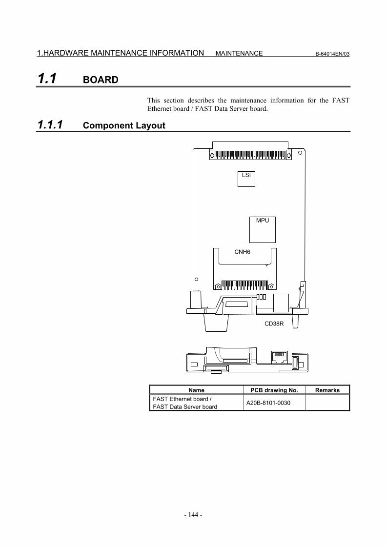
1.HARDWARE MAINTENANCE INFORMATION MAINTENANCE B-64014EN/03
- 144 -
1.1 BOARD This section describes the maintenance information for the FAST Ethernet board / FAST Data Server board.
1.1.1 Component Layout
MPU
LSI
CD38R
CNH6
Name PCB drawing No. Remarks FAST Ethernet board / FAST Data Server board
A20B-8101-0030

B-64014EN/03 MAINTENANCE 1.HARDWARE MAINTENANCE INFORMATION
- 145 -
1.1.2 LED Indications and Meanings The board provides four green LEDs (STATUS) and one red LED (ALARM) for status indication, and provides three green LEDs and one red LED for communication status indication. The figure below shows the locations of these LEDs. The table below explains the LED lighting states. In the following explanations, the LED lighting states are expressed as follows:
: Off : On : Blinking ◊: Don't care
CD38R4(STA
SU
S) (G
RE
EN
)
3(STATU
S) (G
RE
EN
)
2(STATU
S) (G
RE
EN
)
1(STATU
S) (G
RE
EN
)
ALR
(RE
D)
LIL (GR
EE
N)
CO
L (RED
)
CO
M (G
REEN
)
BTX
(GR
EE
N)
NOTE The face plate is indicated using dotted lines.

1.HARDWARE MAINTENANCE INFORMATION MAINTENANCE B-64014EN/03
- 146 -
LED display transition for LED1, LED2, LED3, and LED4 (during power-on) LED indication
L4 L3 L2 L1 Status Meaning
Power-off
Immediately after power-on
Initial state entered immediately after power-on. If the board is stopped in this condition, the cause is one of the following: → The firmware is not stored in the Flash ROM of the
CNC. → The board is defective.
Start of board The board has started. If the board is stopped in this condition, the board may be defective.
Completion of firmware downloading
The firmware has been downloaded to the board. If the board is stopped in this condition, the board may be defective.
Firmware OS started.
The firmware OS has started. If the board is stopped in this condition, the cause is one of the following: → The firmware stored in the Flash ROM of the CNC
is destroyed. → The board is defective.
Completion of firmware OS initialization
Initialization of the firmware OS is completed. If the board is stopped in this condition, the cause is one of the following: → The firmware stored in the Flash ROM of the CNC
is destroyed. → The board is defective.
Completion of parameter reading
The Ethernet parameters have been read. If the board is stopped in this condition, the cause is one of the following: → The Ethernet option or Data Server option is not
installed. → The IP address or subnet mask is not set.
Start completion The board has started normally.
LED display for LED1, LED2, LED3, and LED4 (during normal operation) LED indication
L4 L3 L2 L1 Status Meaning
Normal status The board is operating normally.
LED display for BTX, LIL, COM, and ALM (during normal operation) LED indication Status Meaning
BTX 100BASE-TX connection in progress
The communication rate is 100BASE-TX.
BTX 10BASE-T connection in progress
The communication rate is 10BASE-T.
LIL Connected to hub The board is connected to the hub.
COM Transmission/ reception in progress
Data is being transmitted or received.
ALM No alarm No alarm is issued

B-64014EN/03 MAINTENANCE 1.HARDWARE MAINTENANCE INFORMATION
- 147 -
LED display for LED1, LED2, LED3, and LED4 (when abnormality occurs) The STATUS LEDs are turned on and off repeatedly with long on-time and short on-time.
LED indication
[Long on-time] 4 3 2 1
LED indication
[Short on-time] 4 3 2 1
Status Description
Error on another board
A defect on another board or a problem on another board was detected.
Bus error Software has a problem, or the board is defective. Parity alarm The board is defective.
Illegal general instruction
Software has a problem, or the board is defective.
Illegal slot instruction Software has a problem, or the board is defective. CPU address error Software has a problem, or the board is defective.
NOTE If an error occurs with the LEDs turned on and off
with long on-time and short on-time in a manner not indicated above, contact FANUC.
LED display for COL, LIL, and ALM (when abnormality occurs)
LED indication Status Description
COL COL
Collision occurs. (Data collision occurs.)
The LED is on or blinks at short intervals when the Ethernet communication traffic (communication amount) is high or ambient noise is high.
LIL Not connected to hub
The board is not connected to the hub properly. The LIL LED stays off also when the power to the hub is off. Check whether the board is connected to the hub properly.
ALM Parity error occurs. A parity error occurred in memory on the board. The board is defective.

2.SOFTWARE MAINTENANCE INFORMATION MAINTENANCE B-64014EN/03
- 148 -
2 SOFTWARE MAINTENANCE INFORMATION
This chapter provides software maintenance information related to the FAST Ethernet/FAST Data Server.

B-64014EN/03 MAINTENANCE 2.SOFTWARE MAINTENANCE INFORMATION
- 149 -
2.1 Ethernet LOG A log related to the FAST Ethernet/FAST Data Server is displayed.
ETHERNET LOG screen
Procedure 1 Press the function key MESSAGE . 2 Press soft key [BOARD LOG] to display the LOG screen for the
FAST Ethernet/FAST Data Server. (If the soft key is not found, press the continuous menu key.)
LOG screen
The latest log information is displayed at the top of the screen. At the right end of a log item, the occurrence date and time of the log item is indicated. Date and time data is indicated in the format "MMM.DD hh:mm:ss", where MMM represents a month, DD represents a day, hh represents hours, mm represents minutes, and ss represents seconds. The top item in the example above indicates "09:36:14 on August 7". To clear the log information, press soft key [(OPRT)] then soft key [CLEAR].

2.SOFTWARE MAINTENANCE INFORMATION MAINTENANCE B-64014EN/03
- 150 -
By operating the LOG screen of the FAST Ethernet/FAST Data Server, log information can be displayed for each function. (1) Soft key [ALL] This soft key displays all log information related to the FAST
Ethernet/FAST Data Server. (2) Soft key [COMMON] This soft key displays log information related to the parameter
setting and basic communication function of the FAST Ethernet/FAST Data Server.
(3) Soft key [FOCAS2] This soft key displays log information related to the
FOCAS2/Ethernet function. (4) Soft key [DATA SERVER] This soft key displays log information related to the Data Server. (5) Soft key [REMOTE DIAG] This soft key displays log information related to the machine
remote diagnosis functions.
NOTE The Ethernet log information is stored in volatile
memory and is lost when the power to the CNC is turned off. Check the log information when an error occurs.
Error
number Log message Meaning and action to be taken
E-0118 E-0119
Error occurred while wait for FOCAS2 pdu A communication error occurred due to one of the following causes: → The network quality degraded, data could not be
received from the personal computer with which to communicate, and the logical communication path was disconnected.
→ The software component on the personal computer with which to communicate forcibly disconnected the logical communication path.
→ The Ethernet cable was disconnected. E-011A All communication paths are busy All FOCAS2/Ethernet communication paths are being
used. E-0126 No response from RMT DIAG server The IP address of the machine remote diagnosis
accepting server may be invalid or the power to the machine remote diagnosis accepting server may be off. Check whether the IP address of the machine remote diagnosis accepting server is valid and whether the power to the machine remote diagnosis accepting server is on. Alternatively, the machine remote diagnosis accepting server may not respond to the PING command to increase the security level (such as a firewall setting). Set bit 1 of CNC parameter No. 905 to "1" and connect the server again.
E-012D No response from router The IP address of the router may be invalid or the power to the router may be off. Check whether the IP address of the router is valid and whether the power to the router is on.

B-64014EN/03 MAINTENANCE 2.SOFTWARE MAINTENANCE INFORMATION
- 151 -
Error number Log message Meaning and action to be taken
E-0200 (Received message from FTP server) A message sent from the FTP server is displayed as is. A message containing kanji, hiragana, and/or katakana characters may not be displayed correctly.
E-0202 Connection failed with FTP server The FTP server software may not be running. Run the FTP server software. Alternatively, the setting may be made so that the FTP server cannot be connected to increase the security level (such as a firewall setting). Change the firewall setting so that the FTP server can be connected.
E-0207 The router is not found The IP address of the router may be invalid or the power to the router may be off. Check whether the IP address of the router is valid and whether the power to the router is on.
E-0208 The FTP server is not found The IP address of the FTP server may be invalid or the power to the FTP server may be off. Check whether the IP address of the FTP server is valid and whether the power to the FTP server is on. Alternatively, the FTP server may not respond to the PING command to increase the security level (such as a firewall setting). Set bit 1 of CNC parameter No. 905 to "1" and connect the server again.
E-020B Cannot login into FTP server Check the user name and password for logging in to the FTP server.
E-020C The parameters of FTP server are wrong Check the user name and password for logging in to the FTP server.
E-020D Changing a work folder of host failed Check the work folder for logging in to the FTP server. E-0219 The DNC file is not found Check whether the file for DNC operation is specified
correctly. E-021A The specified file is not found Check whether the specified file is present. E-021B Opening a file failed The file could not be opened.
Check the error code in parentheses. E-021F FTP transfer is busy on BUFFER mode FTP communication could not catch up with data supply.
Correct the file division size. Alternatively, set bit 0 of NC parameter No. 0904 to 1.
E-0220 There is no file in list file No file is defined in the list in the buffer mode. Correct the file list.
E-0221 The specified file already exists The specified file is already present on the memory card of the Data Server. Delete the existing file. Alternatively, change the file name.
E-0223 Writing data to the file failed Data could not be written to the memory card of the Data Server. Check the error code in parentheses.
E-023A The specified file is busy The file on the memory card of the Data Server is currently used. When a file on the memory card is selected as a main program, the file is regarded as being used.
E-0252 Contents of ATA card are broken Format the memory card of the Data Server. E-02F0 ATA card is not found Check whether a memory card is installed in the Data
Server. E-02F3 ATA card is not mounted Check whether the memory card of the Data Server is
destroyed and whether the memory card has been formatted.

2.SOFTWARE MAINTENANCE INFORMATION MAINTENANCE B-64014EN/03
- 152 -
Error number Log message Meaning and action to be taken
E-041A Frame transmission failed (TCP) A communication error occurred due to one of the following causes: → The network quality degraded, data could not be
received from the personal computer with which to communicate, and the logical communication path was disconnected.
→ The software component on the personal computer with which to communicate forcibly disconnected the logical communication path.
→ The Ethernet cable was disconnected. → Data cannot be posted to the communication
destination due to a firewall setting. E-0A02 Cannot read MAC address The MAC address may not be written on the FAST
Ethernet board or FAST Data Server board or the board may be damaged.
E-0A06 Network is too busy An excessive amount of data flows over the network. Take action such as dividing the network.
E-0B00 The own IP address is wrong Set the IP address according to the IP address specification format.
E-0B01 The own IP address is not set Set the IP address. E-0B02 Subnet mask is wrong Set the subnet mask according to the subnet mask
specification format. E-0B03 Subnet mask is not set Set the subnet mask. E-0B04 Router IP address is wrong There may be a conflict between the classes of the local
node and router IP addresses. E-0B05 IP address of DNS server is wrong There may be a conflict between the classes of the local
node and DNS server IP addresses. E-0B06 The own host name is wrong Check the host name setting. E-0B07 The own domain name is wrong Check the domain name setting. E-0B08 TCP port number is wrong A value outside the valid setting range may be set. E-0B09 UDP port number is wrong A value outside the valid setting range may be set. E-0B0B IP address of remote FTP server is wrong Set the IP address according to the IP address
specification format. E-0B0C Port number of a remote FTP server is wrong A value outside the valid setting range may be set. E-0B0D User name of remote FTP server is wrong A character unavailable for a user name may be used. E-0B0E Password of remote FTP server is wrong A character unavailable for a password may be used. E-0B0F Login folder of remote FTP srv is wrong A character unavailable for a login folder name may be
used. E-0B10 Port number of own FTP server is wrong A value outside the valid setting range may be set. E-0B11 User name of own FTP server is wrong A character unavailable for a user name may be used. E-0B12 Password of own FTP server is wrong A character unavailable for a password may be used. E-0B13 Login folder of own FTP server is wrong A character unavailable for a login folder name may be
used. E-0B14 IP address of Remote Diag is wrong Set the IP address of the machine remote diagnosis
accepting server according to the IP address specification format.
E-0B15 Port number of Remote Diag is wrong A value outside the valid setting range may be set. E-0B18 Cannot set because DHCP is available To set the item, disable the DHCP client function. E-XXXX (No message) Internal error.
Report the error number.

B-64014EN/03 MAINTENANCE 2.SOFTWARE MAINTENANCE INFORMATION
- 153 -
The meanings of the error codes indicated in error messages are as follows:
Error code Meaning
2 The available space of the memory card of the Data Server is insufficient.
10 The specified folder cannot be found. 11 The allowable number of entries is exceeded. 12 Access to a folder was rejected. 14 The specified file cannot be found. 15 Access to a file was rejected. 19 An attempt was made to access a file being used. 22 The specified file name is illegal. 28 A TV check error was detected. 36 The specified file is already present. 37 The folder is not empty. 39 The specified folder is already present. 48 The available file size is exceeded.

2.SOFTWARE MAINTENANCE INFORMATION MAINTENANCE B-64014EN/03
- 154 -
2.2 ETHERNET CONNECTION CONFIRMATION By transmitting the PING command, the CNC can check that a connection is made with the communication destination.
PING screen (connection state confirmation)
Procedure 1 Press the function key SYSTEM . 2 Soft key [ETHER BOARD] is displayed. (If the soft key is not
found, press the continuous menu key.) 3 Press soft key [ETHER BOARD] then soft key [PING].
PING (CONNECT STATE) screen
4 Press soft key [(OPRT)] then soft key [PING FTP1] to send the
PING command to host 1 to which the Data Server function is connected. Similarly, press soft key [PING FTP2] and soft key [PING FTP3] to send the PING command to connection hosts 2 and 3, respectively.

B-64014EN/03 MAINTENANCE 2.SOFTWARE MAINTENANCE INFORMATION
- 155 -
5 Press soft key [(OPRT)] then soft key [PING RMT1] to send the PING command to inquiry destination 1 of the machine remote diagnosis functions. Similarly, press soft key [PING RMT2] to send the command to inquiry destination 2 and soft key [PING RMT3] to inquiry destination 3.
The results of PING execution are as follows:
Execution results of PING

2.SOFTWARE MAINTENANCE INFORMATION MAINTENANCE B-64014EN/03
- 156 -
PING (SETTING) screen
Procedure 1 When sending the PING command to a desired destination, enter
the destination address in HOSTNAME (IP ADDRESS) on the PING (SETTING) screen. Moreover, set a desired execution repeat value in REPEAT.
PING (SETTING) screen
2 After entering a host name (IP address) and repeat value, press
soft key [(OPRT)] then soft key [PING EXEC] to send the PING command to the specified destination.
3 To cancel the transmission of the PING command halfway, press soft key [PING CANCEL].

B-64014EN/03 MAINTENANCE 2.SOFTWARE MAINTENANCE INFORMATION
- 157 -
2.3 COMMUNICATION STATE CONFIRMATION The communication state of the FAST Ethernet/FAST Data Server detected by hardware can be checked.
COM STATE (SEND / RECEIVE) screen
Procedure 1 Press the function key SYSTEM . 2 Soft key [ETHER BOARD] is displayed. (If the soft key is not
found, press the continuous menu key.) 3 Press soft key [ETHER BOARD] then soft key [COM STATE]
to display the COM STATE screen.
COM STATE screen
Display item
Display item Description BAUDRATE Displays the communication rate and mode.
Communication rate: 100 Mbps or 10 Mbps Communication mode: Full duplex or Half duplex
SEND PACKET Displays the number of sent packets. SEND RETRYOVER COLLISION CARRIER SENSE LOST NO CARRIER FRAME LENGTH ERROR
Displays the number of errors detected during packet sending.
RECEIVE PACKET Displays the number of received packets. CRC ERROR SHORT FRAME LONG FRAME ODD FRAME OVERFLOW PHY-LSI ERROR
Displays the number of errors detected during packet reception.

2.SOFTWARE MAINTENANCE INFORMATION MAINTENANCE B-64014EN/03
- 158 -
2.4 COMMUNICATION SOFTWARE CONFIRMATION The operating status of the software of the FAST Ethernet/FAST Data Server can be checked.
TASK STATE screen
Procedure 1 Press the function key SYSTEM . 2 Soft key [ETHER BOARD] is displayed. (If the soft key is not
found, press the continuous menu key.) 3 Press soft key [ETHER BOARD] then soft key [TASK STATE]
to display the TASK STATE screen.
TASK STATE screen

B-64014EN/03 MAINTENANCE 2.SOFTWARE MAINTENANCE INFORMATION
- 159 -
Display item The meaning of each symbol is indicated below.
Symbol and meaning COMMON W : Data being processed (1)
D : Data being processed (2) E : Start of software
FOCAS2 #0 C : Waiting for connection from the host W : Data being processed (1) D : Data being processed (2) N : FOCAS2 incapable of being executed
FOCAS2 #1 W : Data being processed (1) D : Data being processed (2) X : Not executed yet
FOCAS2 #2 W : Data being processed (1) D : Data being processed (2) X : Not executed yet
SCREEN W : Data being processed (1) D : Data being processed (2) X : Not executed yet
UDP W : Data being processed (1) D : Data being processed (2) X : Not executed yet
PMC W : Data being processed (1) D : Data being processed (2) X : Not executed yet
DATASERVER W : Data being processed (1) D : Data being processed (2) X : Not executed yet
FTP SERVER W : Data being processed (1) D : Data being processed (2) Number : Number of sockets currently connected
FREMOTE DIAG W : Data being processed (1) D : Data being processed (2) X : Not executed yet
When the FOCAS2/Ethernet functions are running, you can check the operating status from: FOCAS2#0, FOCAS2#1, and FOCAS2#2. When the CNC screen display functions are running, you can check the operating status from: SCREEN When the FANUC LADDER-III functions are running, you can check the operating status from: PMC When the Data Server functions are running, you can check the operating status from: DATASERVER and FTP SERVER When the Machine Remote Diagnosis functions are running, you can check the operating status from: REMOTE DIAG


APPENDIX


B-64014EN/03 APPENDIX A.TROUBLESHOOTING
- 163 -
A TROUBLESHOOTING This appendix describes troubleshooting related to FAST Ethernet/ FAST Data Server communication.

A.TROUBLESHOOTING APPENDIX B-64014EN/03
- 164 -
A.1 CHECKING COMMUNICATION WITH A HUB (1) Make sure that the STP cable between the hub and the FAST
Ethernet/FAST Data Server is connected. (2) Make sure that cables are properly wired.
• Though communication is carried out when the cable pair at the send and receive sides is not properly mounted, communications errors may occur more frequently.
(3) Make sure that a hub for 100BASE-TX is used. • A hub for 10BASE-T may be used to perform
communication. In this case, however, the communication speed can decrease.
(4) Make sure that the LIL LED on the FAST Ethernet/FAST Data Server is lit at all times. • The LIL LED will not light if the FAST Ethernet/FAST
Data Server is not connected to the hub or if the hub is not ON.
(5) Make sure that the LED (LINK indicator LED) on the connected hub is lit at all times. • Some hubs do not have a LINK indicator LED. • The LINK indicator LED will not light if the hub is not
connected to the FAST Ethernet/FAST Data Server or the CNC is not ON.
(6) Make sure that a hub for full duplex communication only is not used. • The FAST Ethernet/FAST Data Server automatically
detects the communication speed and communication mode (full duplex or half duplex) by using the auto negotiation function. In communication with a hub that does not have the auto negotiation function, the FAST Ethernet/FAST Data Server recognizes the communication speed correctly but regards the communication mode as half duplex communication.
As a result, when an attempt is made to communicate with a hub for full duplex communication only that does not have the auto negotiation function, there is a discrepancy in communication mode, so correct communication cannot sometimes be performed.
• For details on how to connect, see Part V "CONNECTION."

B-64014EN/03 APPENDIX A.TROUBLESHOOTING
- 165 -
A.2 CHECKING CONNECTION WITH THE TRUNK General notes are provided below. For network installation, consult with specialized vendors or manufacturers. Run cables away from noise sources. The descriptions below are not applicable if the network is configured using only those hubs that have Ethernet boards connected. • When the trunk is based on 10BASE-5
(1) Make sure that a transceiver is attached to the trunk correctly. - If a transceiver is attached correctly, the resistance
between the trunk shield and central conductor is about 25Ω (when a terminating resistor is attached).
- A special tool is required to attach a transceiver. (No special tool is required, depending on the manufacturer. For details, refer to the installation manual of each transceiver.)
- Do not attach a transceiver again to a point where a transceiver was once attached. (Otherwise, the cable can be damaged.)
(2) Make sure that transceivers are attached at proper intervals. - Transceivers must be attached at intervals of 2.5 m or
more. It is recommended that transceivers be attached at intervals of an integral multiple of 2.5 m. Usually, marks indicating installation points are provided on the trunk cable.
(3) Make sure that terminating resistors are attached. - A terminating resistor must be attached to each end of
the trunk cable. (Resistance: 50Ω) (4) Make sure that the trunk cable is not longer than 500 m. (5) Make sure that the cable (transceiver cable) used for
connection between a transceiver and the hub is not longer than a specified limit. - Usually, the maximum allowable length of a
transceiver cable is 50 m. However, the maximum allowable length of a cable with a smaller diameter may be shorter than 50 m. So, check the specifications of each cable.
• When the trunk is based on 10BASE-2
(1) Make sure that the length of each cable is 0.5 m or more. - The minimum allowable distance between nodes
(units) is 0.5 m. (2) Make sure that the trunk cable length (sum of the lengths of
cables) is 185 m or less. (3) Make sure that terminating resistors are attached.
- A terminating resistor must be attached to each end of the trunk cable. (Resistance: 50Ω)

A.TROUBLESHOOTING APPENDIX B-64014EN/03
- 166 -
A.3 CHECKING SETTINGS The following describes how to check the minimum settings needed for communications.
NOTE For details on IP addresses, subnet mask and other
set values, consult with the network administrator. • Checking settings on the FAST Ethernet/FAST Data Server
(1) Make sure that the MAC address of the FAST Ethernet/FAST Data Server is displayed. - This address is appended to each board before
shipment from the factory, and is automatically displayed in the Setting screen. This address need not be set by the user.
(2) Make sure that the IP address is set. (3) Make sure that the subnet mask is set. (4) When a router is used, make sure that the router IP address
is set. • Checking settings on the personal computer
(1) Make sure that the IP address is set. (2) Make sure that the subnet mask is set. (3) When a router is used, make sure that the router IP address
is set. • For details on how to set, see Part III "SETTING."

B-64014EN/03 APPENDIX A.TROUBLESHOOTING
- 167 -
A.4 CHECKING COMMUNICATION This section describes how to check the communication status between a CNC and the other communicating partner (host computer). If communication with the CNC sometimes fails or is not possible, first make sure that the communication path is normal by the following procedure. The "ping" command is used to check communication. In the following example, a host computer running the Windows NT4.0 is used. • Checking the communication path Open the DOS window, and enter 'ping "IP address of CNC"'. If
a response is returned from the CNC, the FAST Ethernet/FAST Data Server is connected to the CNC. (1) When a response is returned (normal connection)
(2) When a response is not returned (abnormal connection)
When a response is not returned, probable causes are either
the hardware connection or a software setting, or both. Check the hardware connections and software settings again.

A.TROUBLESHOOTING APPENDIX B-64014EN/03
- 168 -
• Checking IP addresses for duplication IP addresses can be checked for duplication by the procedure
described below. (1) Disconnect the Ethernet cable from the CNC to isolate it
from the network. (2) Execute a ping command on another personal computer as
described in "• Checking the communication path." Since the CNC is disconnected from the network, no
response should be returned. If a response is returned, the IP address is in use on another unit. Therefore, the IP address cannot be used on the CNC from which the cable was disconnected.
CAUTION
The purpose of this check is to check for a duplicate IP address. It does not assure that the IP address is left non-duplicated because a unit having the same IP address may be turned on after the check or the same address may be set later. When setting an IP addressing, ask the network manager about duplication.
• Checking for influence of electrical noise The "ping" command "-t" option is used for checking for the
influence of electrical noise. This option sends ping packets until "Ctrl+C" is pressed.

B-64014EN/03 APPENDIX A.TROUBLESHOOTING
- 169 -
1. About the influence of electrical noise from peripheral machinery (devices) (1) Turn the CNC is mounted ON to enable
communications. (2) Press the EMERGENCY STOP button on the machine
with the servo/spindle amplifier OFF, and issue the "ping" command from the host computer.
(3) Count the number of lost packets (packets for which a response was not returned).
If a lost packet occurs in this state, the machine is probably being affected by electrical influence from peripheral machines.
Countermeasure: Pin-point the source of the electrical noise, and
check the wiring again to prevent the influence of electrical noise.
2. About the influence of electrical noise from mounted
machinery (1) Start up the machine in the same way as 1 above. (2) Cancel the emergency stop on the machine with the
servo/spindle amplifier ON, and issue the "ping" command from the host computer.
(3) Count the number of lost packets. If more lost packets than in 1 above are occurring, a
probable cause is the influence of electrical noise on the machine itself. General probable causes are the state of the ground on the machine or on the communicating party.
Countermeasure: Check the state of the ground on the machine or on
the communicating party, and insulate the communications trunk with the machine.
• For the method of checking the operating status and
communication status of the FAST Ethernet/FAST Data Server, see Part VI “MAINTENANCE” as well.

B.EXAMPLE OF FTP SERVER SETUP APPENDIX B-64014EN/03
- 170 -
B EXAMPLE OF FTP SERVER SETUP This appendix describes the method of setting up an FTP server that operates on the host computer to function as a communication destination for the Data Server functions.

B-64014EN/03 APPENDIX B.EXAMPLE OF FTP SERVER SETUP
- 171 -
B.1 SETTING UP FTP SERVER OF Windows 2000 Professional (FOR INTERNET INFORMATION SERVICE)
Installing the Internet Information Service
1. Set the CD-ROM of Windows 2000 Professional.
2. Click [Install Add-On Components].
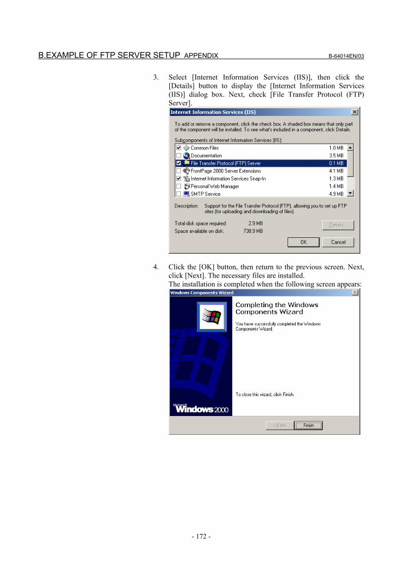
B.EXAMPLE OF FTP SERVER SETUP APPENDIX B-64014EN/03
- 172 -
3. Select [Internet Information Services (IIS)], then click the [Details] button to display the [Internet Information Services (IIS)] dialog box. Next, check [File Transfer Protocol (FTP) Server].
4. Click the [OK] button, then return to the previous screen. Next,
click [Next]. The necessary files are installed. The installation is completed when the following screen appears:

B-64014EN/03 APPENDIX B.EXAMPLE OF FTP SERVER SETUP
- 173 -
Setting the Internet Information Service 1. Select [Start] → [Settings] → [Control Panel].
2. Double-click [Administrative Tools].

B.EXAMPLE OF FTP SERVER SETUP APPENDIX B-64014EN/03
- 174 -
3. Double-click [Internet Service Manager] for activation.
4. Double-click the computer name. Next, select [Default FTP Site]
and right-click to display the menu. Then, select Properties.

B-64014EN/03 APPENDIX B.EXAMPLE OF FTP SERVER SETUP
- 175 -
5. Select the [Home Directory] tab to display the [Home Directory] property sheet. Check [Read] and [Write] in [FTP Site Directory]. In [Directory Listing Style], [MS-DOS] is selected by default. However, it is recommended to check [UNIX]. If files are listed in UNIX format, whether each file is accessible can be determined.
6. Upon completion of setting, click the [Apply] button. In [Default FTP Site], the directory named "\Inetpub\ftproot", set
in [Local Path] above (in the drive where Windows 2000 is installed), is assumed to be the home directory. So, directories under this directory can be accessed.
So, with the default setting, NC programs need to be managed under this directory.
The home directory can be changed by setting the new directory in the [Local Path] of [FTP Site Directory].
7. To access a directory other than the directories under the home
directory, a virtual directory needs to be set. For details of a virtual directory, use the online help information of Windows 2000.

B.EXAMPLE OF FTP SERVER SETUP APPENDIX B-64014EN/03
- 176 -
Login user setting 1. Select [Start] → [Settings] → [Control Panel].
2. Double-click the icon [Users and Passwords].

B-64014EN/03 APPENDIX B.EXAMPLE OF FTP SERVER SETUP
- 177 -
3. Click the [Add] button, then enter necessary items such as a user name.
4. Click the [Next] button, then enter a password for the specified
user name. (Unless a password is set, access to the FTP server cannot be made correctly. So, be sure to enter a password.)

B.EXAMPLE OF FTP SERVER SETUP APPENDIX B-64014EN/03
- 178 -
5. Click the [Next] button, then set an access right to be granted. The access right set here can affect the capability to read from
and write to a file in FTP-based communication. Use care when setting an access right.
6. Click the [Finish] button. The entered user name is registered,
and the user can log in by using the user name and password.

B-64014EN/03 APPENDIX B.EXAMPLE OF FTP SERVER SETUP
- 179 -
Stopping password expiration for a login user If the password expiration is not stopped, when the password expires, login is disabled, preventing FTP communication. Therefore, stop the password expiration as necessary. When a password has expired, it is necessary to set the password again. 1. Select [Start] → [Settings] → [Control Panel].
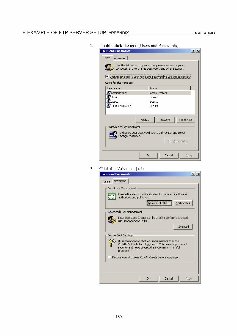
B.EXAMPLE OF FTP SERVER SETUP APPENDIX B-64014EN/03
- 180 -
2. Double-click the icon [Users and Passwords].
3. Click the [Advanced] tab.

B-64014EN/03 APPENDIX B.EXAMPLE OF FTP SERVER SETUP
- 181 -
4. Click the [Advanced] button.
5. Double-click [Users]. A list of registered users is displayed.

B.EXAMPLE OF FTP SERVER SETUP APPENDIX B-64014EN/03
- 182 -
6. Double-click the user name for which you want to change the password setting.
For example, double-click "dtsvr".
7. Check [Password never expires] and then click the [OK] button.
The password expiration is stopped.

B-64014EN/03 APPENDIX B.EXAMPLE OF FTP SERVER SETUP
- 183 -
B.2 SETTING UP FTP SERVER OF Windows XP Professional (FOR INTERNET INFORMATION SERVICE)
NOTE Windows XP Home Edition does not have IIS
(Internet Information Service).
Installing the Internet Information Service 1. Open [Control Panel] of Windows XP Professional.
2. Double-click [Add or Remove Programs].

B.EXAMPLE OF FTP SERVER SETUP APPENDIX B-64014EN/03
- 184 -
3. Double-click [Add/Remove Windows Components].
4. Select [Internet Information Services (IIS)], then click the
[Details] button to display the [Internet Information Services (IIS)] dialog box. Next, check [File Transfer Protocol (FTP) Service].

B-64014EN/03 APPENDIX B.EXAMPLE OF FTP SERVER SETUP
- 185 -
5. Click the [OK] button, then return to the previous screen. Next, click [Next].
6. The dialog box above is displayed, and the necessary files are
installed.
7. The installation is completed when the screen above is displayed.

B.EXAMPLE OF FTP SERVER SETUP APPENDIX B-64014EN/03
- 186 -
Setting the Internet Information Service 1. Open [Control Panel] of Windows XP Professional.
2. Click [Performance and Maintenance].

B-64014EN/03 APPENDIX B.EXAMPLE OF FTP SERVER SETUP
- 187 -
3. Click [Administrative Tools].
4. Double-click [Internet Information Services].

B.EXAMPLE OF FTP SERVER SETUP APPENDIX B-64014EN/03
- 188 -
5. Double-click [FTP Site], right-click [Default FTP Site] to display a menu, then select Properties.
6. Select the [Home Directory] tab to display the [Home Directory]
property sheet. Check [Read] and [Write] in [FTP Site Directory]. In [Directory Listing Style], [MS-DOS] is selected by default. However, it is recommended to check [UNIX]. If files are listed in UNIX format, whether each file is accessible can be determined.
B-64014EN/03 APPENDIX B.EXAMPLE OF FTP SERVER SETUP
- 189 -
7. Then, click the [OK] button. In the standard [Default FTP Site], the directory \Inetput\ftproot
(on the drive where Windows XP is installed) is the home directory, and only the directories under the home directory can be accessed.
To use a directory other than the default directory as a home directory, modify the local path of [FTP Site Directory] mentioned in step 6 above.
8. To access a directory other than the directories under the home
directory set in step 7 above, a virtual directory needs to be set. For details of a virtual directory, use information such as the
online help information of Windows XP.

B.EXAMPLE OF FTP SERVER SETUP APPENDIX B-64014EN/03
- 190 -
Login user setting 1. Open [Control Panel] of Windows XP Professional.
2. Double-click the icon of [User Accounts].

B-64014EN/03 APPENDIX B.EXAMPLE OF FTP SERVER SETUP
- 191 -
3. Click [Create a new account], then enter a desired user name.
4. Click the [Next] button, then set an account type. The access right set here can affect the capability to read from
and write to a file in FTP-based communication. Use care when setting an access right.

B.EXAMPLE OF FTP SERVER SETUP APPENDIX B-64014EN/03
- 192 -
5. Click the [Create Account] button, then the creation of an account is completed.
6. For password setting, click the previously created account in [or
pick an account to change]. (The FTP server cannot be accessed without setting a password. So, be sure to execute this step.)

B-64014EN/03 APPENDIX B.EXAMPLE OF FTP SERVER SETUP
- 193 -
7. Click [Create a password], then enter a password for the specified user name.
8. Click the [Create Password] button to register the entered
password. By using the account registered this time, the user can log in to the FTP server.

B.EXAMPLE OF FTP SERVER SETUP APPENDIX B-64014EN/03
- 194 -
Stopping password expiration for a login user If the password expiration is not stopped, the Data Server will not be able to communicate with the FTP server at the time of expiring the password. If you are necessary, stop the password expiration. If the password is expired, it is necessary that you re-enter the password. 1. Select [Start] → [All Programs] → [Accessories] → [Command
Prompt].
2. Input “net user login-user /expires:never”.
3. If the above message is displayed, the password expiration is
stopped.

B-64014EN/03 APPENDIX B.EXAMPLE OF FTP SERVER SETUP
- 195 -
Confirming the Firewall function of Windows XP Because the Internet Connection Firewall function is included in the Windows XP Professional, the Data Server cannot communicate with the FTP server. If the FTP connection cannot be established, confirm the following setting of the Internet Connection Firewall function.
NOTE When settings are made as described below, the
FTP server functions and response to PING, which have been disabled by the network security function, are enabled.
Therefore, when making the following settings, consult with your network administrator, and take special care.
In some cases, it becomes necessary to isolate the network from the outside as required.
1. Open [Control Panel] of Windows XP Professional.

B.EXAMPLE OF FTP SERVER SETUP APPENDIX B-64014EN/03
- 196 -
2. Click the icon of [Network and Internet Connections].
3. Click the icon [Network Connections].

B-64014EN/03 APPENDIX B.EXAMPLE OF FTP SERVER SETUP
- 197 -
4. Right-click the icon [Local Area Connection] to display the menu. Then, select Properties.
5. Select the [Advanced] tab.

B.EXAMPLE OF FTP SERVER SETUP APPENDIX B-64014EN/03
- 198 -
6. If [Internet Connection Firewall] is not checked, the Internet Connection Firewall function does not work. Then, the following confirmations are not necessary.
7. If [Internet Connection Firewall] is checked, click the
[Settings…] button.
8. If the [FTP Server] check-box is not checked, the FTP server
function does not work. Check the [FTP Server] check-box. When the [FTP Server] check-box is cheked, the following window is diplayed. Then, click the [OK] button.

B-64014EN/03 APPENDIX B.EXAMPLE OF FTP SERVER SETUP
- 199 -
9. Select the [ICMP] tab.

B.EXAMPLE OF FTP SERVER SETUP APPENDIX B-64014EN/03
- 200 -
10. If the [Allow incoming echo request] check-box is not checked, the Data Server function cannot find the FTP server at the start of communication. At the start of communication of Data Server, if the message “[FTP] (IP-address) IS NOT AVAILABLE” is displayed, check this check-box.

B-64014EN/03 APPENDIX B.EXAMPLE OF FTP SERVER SETUP
- 201 -
Confirming the firewall function when Windows XP (Service Pack 2) is used When Windows XP Professional (Service Pack 2) is used, a different firewall setting procedure is used. 1. Open [Control Panel] of Windows XP Professional.
2. Double-click [Security Center] to start it.

B.EXAMPLE OF FTP SERVER SETUP APPENDIX B-64014EN/03
- 202 -
3. Click [Windows Firewall] displayed at the bottom.

B-64014EN/03 APPENDIX B.EXAMPLE OF FTP SERVER SETUP
- 203 -
4. Select the [Advanced] tab.
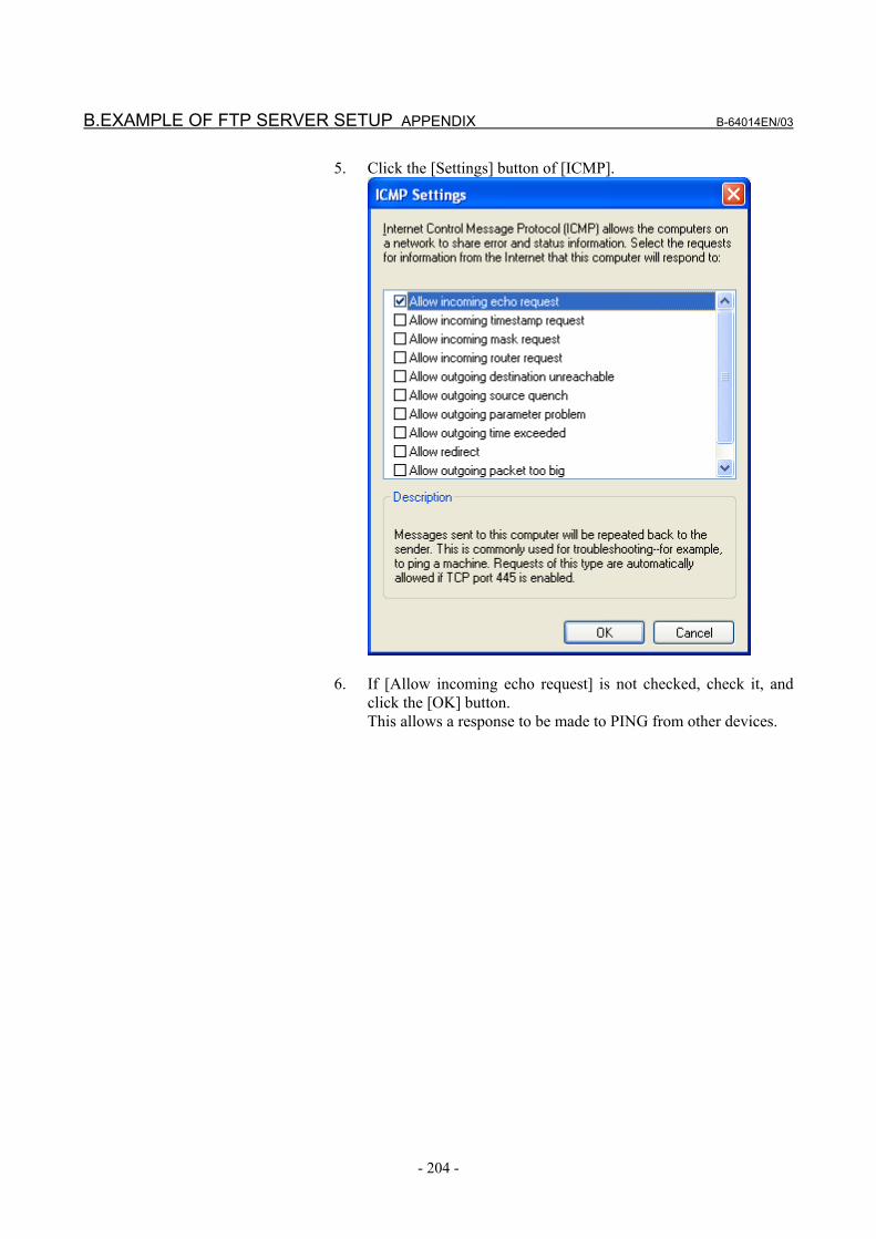
B.EXAMPLE OF FTP SERVER SETUP APPENDIX B-64014EN/03
- 204 -
5. Click the [Settings] button of [ICMP].
6. If [Allow incoming echo request] is not checked, check it, and
click the [OK] button. This allows a response to be made to PING from other devices.

B-64014EN/03 APPENDIX B.EXAMPLE OF FTP SERVER SETUP
- 205 -
7. Select the [Exceptions] tab.
8. Click the [Add Port] button, and make settings as follows:

B.EXAMPLE OF FTP SERVER SETUP APPENDIX B-64014EN/03
- 206 -
9. Click the [OK] button.

B-64014EN/03 APPENDIX C.EXAMPLE OF SETTING UP DNS/DHCP
- 207 -
C EXAMPLE OF SETTING UP DNS/DHCP This appendix describes the method of setting up the DNS/DHCP server of Windows 2000 Server.
Example of setting a simple network An example of setup in a network configuration that satisfies the following conditions is provided: 1. The DHCP server and DNS server are operated using the same
personal computer. 2. The IP address of the DHCP server and DNS server is
192.168.0.254. 3. The DHCP server controls the IP address range 192.168.0.10 to
192.168.0.29. 4. The domain controlled by the DNS server is named "factory". 5. The same domain includes the DHCP server, DNS server, CNCs,
and a PC for FOCAS1/Ethernet applications.
. . .
Windows 2000 Server DNS server
DHCP server 192.168.0.254
Domain : factory
CNC Automatic setting
PCAutomatic setting
CNC Automatic setting
Example of network configuration
NOTE The setting described above is just an example.
For setup in an actual network configuration in the factory, consult with the network administrator of the factory.

C.EXAMPLE OF SETTING UP DNS/DHCP APPENDIX B-64014EN/03
- 208 -
C.1 EXAMPLE OF SETTING UP DHCP SERVER OF Windows 2000 Server
1. Activating the Microsoft administrative console (DHCP)
Click [Programs] → [Administrative Tools] → [DHCP].
2. Adding a scope Click [Action] → [New Scope] to start “New Scope Wizard”.
Click the [Next] button.

B-64014EN/03 APPENDIX C.EXAMPLE OF SETTING UP DNS/DHCP
- 209 -
Enter "factory" as [Name], and enter "FACTORY" as [Description].
Click the [Next] button. Enter “192.168.0.10” as [Start IP address], enter “192.168.0.29” as [End IP address], enter “24” as [Length], and enter “255.255.255.0” as [Subnet mask].
Click the [Next] button.

C.EXAMPLE OF SETTING UP DNS/DHCP APPENDIX B-64014EN/03
- 210 -
Click the [Next] button without entering any data.
Keep "8" days unchanged as Period, then click the [Next] button.
Keep [Yes, I want to configure these options now] selected, and click the [Next] button.

B-64014EN/03 APPENDIX C.EXAMPLE OF SETTING UP DNS/DHCP
- 211 -
Click the [Next] button without entering any data. Enter “192.168.0.254” as IP Address, then click [Add].
Click the [Next] button.
Click the [Next] button without entering any data.

C.EXAMPLE OF SETTING UP DNS/DHCP APPENDIX B-64014EN/03
- 212 -
Keep [Yes, I want to activate this scope now] selected, and click the [Next] button.
Click [Finish].

B-64014EN/03 APPENDIX C.EXAMPLE OF SETTING UP DNS/DHCP
- 213 -
3. Adding a scope option Click [Scope[192.168.0.0]factory], then click [Scope Options] → [Action] → [Configure Options].
From the available options, find and check [DNS Domain Name]. Then, enter "factory" as String value.
Click the [OK] button. The following setting is made:

C.EXAMPLE OF SETTING UP DNS/DHCP APPENDIX B-64014EN/03
- 214 -
4. Enabling Dynamic DNS Click [Scope[192.168.0.0]factory] → [Properties] → [DNS].
Check [Always update DNC] and [Enable updates for DNS clients that do not support dynamic update].
Click the [OK] button. This completes DHCP server setting.
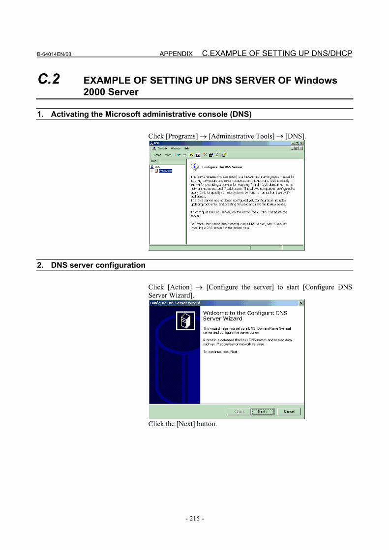
B-64014EN/03 APPENDIX C.EXAMPLE OF SETTING UP DNS/DHCP
- 215 -
C.2 EXAMPLE OF SETTING UP DNS SERVER OF Windows 2000 Server
1. Activating the Microsoft administrative console (DNS)
Click [Programs] → [Administrative Tools] → [DNS].
2. DNS server configuration Click [Action] → [Configure the server] to start [Configure DNS Server Wizard].
Click the [Next] button.

C.EXAMPLE OF SETTING UP DNS/DHCP APPENDIX B-64014EN/03
- 216 -
Keep [This is the first DNS server on this network] selected, and click the [Next] button.
Keep [Yes, create a forward lookup zone], and click the [Next] button.
Keep [Standard primary] selected, and click the [Next] button.

B-64014EN/03 APPENDIX C.EXAMPLE OF SETTING UP DNS/DHCP
- 217 -
Enter "factory." as Name. (Do not fail to enter "." after "factory".)
Click the [Next] button.
Keep “factory.dns” unchanged, and click the [Next] button.
Keep [Yes, create a reverse lookup zone] selected, and click the [Next] button.

C.EXAMPLE OF SETTING UP DNS/DHCP APPENDIX B-64014EN/03
- 218 -
Keep [Standard primary] selected, and click the [Next] button. Enter “192.168.0” as Network ID.
Click the [Next] button.
Keep “0.168.192.in-addr.arpa.dns” unchanged, and click the [Next] button.
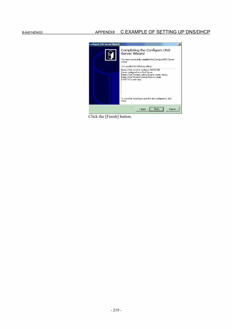
B-64014EN/03 APPENDIX C.EXAMPLE OF SETTING UP DNS/DHCP
- 219 -
Click the [Finish] button.

C.EXAMPLE OF SETTING UP DNS/DHCP APPENDIX B-64014EN/03
- 220 -
3. Enabling Dynamic DNS Right-click [Forward Lookup Zones] → [factory].
Click [Properties]. For [Allow dynamic updates?], select [Yes].
Click the [OK] button. This completes DNS server setting.

B-64014EN/03 APPENDIX D.FTP CLIENT OPERATION
- 221 -
D FTP CLIENT OPERATION This appendix describes the method of operating an FTP client that operates on the host computer to function as a communication destination for the Data Server functions.

D.FTP CLIENT OPERATION APPENDIX B-64014EN/03
- 222 -
D.1 OPERATION USING THE FTP COMMAND
Login 1 Enter "ftp IP-address-of-NC or host-name" at the command
prompt. 2 Enter a user name. 3 Enter a password. 4 The message, "230 User logged in, proceed." indicates that the
login process has been completed successfully.
GET (acquiring a file from the FTP server) 1 Enter "get hard-disk-file-name."
MGET (acquiring files from the FTP server) 1 Enter "mget hard-disk-file-name (including a wildcard
character)."

B-64014EN/03 APPENDIX D.FTP CLIENT OPERATION
- 223 -
PUT (sending a file to the FTP server) 1 Enter "put host-file-name hard-disk-file-name."
MPUT (sending files to the FTP server) 1 Enter "mput host-file-name (including a wildcard character)."
DIR (acquiring a list of files of the FTP server) 1 Enter dir.
DEL (deleting a file from the FTP server) 1 Enter "del hard-disk-file-name."
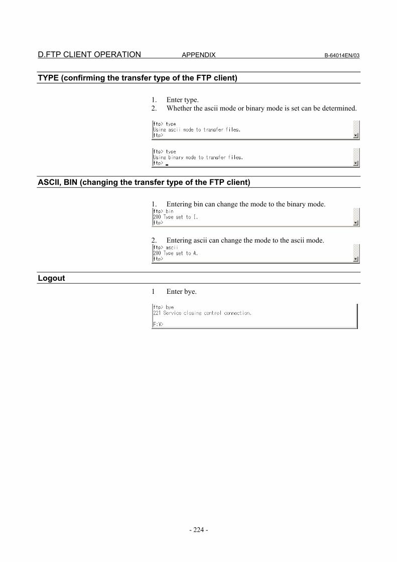
D.FTP CLIENT OPERATION APPENDIX B-64014EN/03
- 224 -
TYPE (confirming the transfer type of the FTP client) 1. Enter type. 2. Whether the ascii mode or binary mode is set can be determined.
ASCII, BIN (changing the transfer type of the FTP client) 1. Entering bin can change the mode to the binary mode.
2. Entering ascii can change the mode to the ascii mode.
Logout 1 Enter bye.

B-64014EN/03 APPENDIX D.FTP CLIENT OPERATION
- 225 -
D.2 SECURITY UNBLOCKING IN Windows XP (Service Pack 2)
When an attempt is made to start FTP communication for the first time in Windows XP (Service Pack 2), the security alert shown below may appear. If the alert appears, consult with the network administrator, and select "Unblock" as necessary.
CAUTIOJN Since selecting "Unblock" means change in
settings related to network security, be sure to consult with the network administrator in advance.
If "Unblock" is selected carelessly, network security can be compromised.


B-64014EN/03 INDEX
i-1
INDEX <Number>
100BASE-TX CONNECTOR (CD38R) PIN
ASSIGNMENTS...........................................................129
<A> ABOUT DNS/DHCP ......................................................27
APPLICABLE MODELS .................................................5
<B> BOARD.........................................................................144
<C> CABLE CONNECTION...............................................126
Cable Connection ..........................................................130
Cable Materials .............................................................131
CHECK ITEMS AT INSTALLATION ........................139
CHECKING COMMUNICATION............................... 167
CHECKING COMMUNICATION WITH A HUB ......164
CHECKING CONNECTION WITH THE TRUNK.....165
CHECKING SETTINGS ..............................................166
Clamping and Shielding Cables ....................................134
COMMUNICATION SOFTWARE
CONFIRMATION ........................................................158
COMMUNICATION STATE CONFIRMATION........157
Component Layout........................................................144
CONNECTING TO Ethernet ........................................127
Connector Specification ................................................133
CONTROLLING THE MACHINE REMOTE
DIAGNOSIS FUNCTIONS FROM THE PMC..............73
<D> DATA SERVER FILE MANAGEMENT.......................11
DATA SERVER FUNCTIONS ......................................10
DATA SERVER MODES...............................................14
DEFINITION OF WARNING, CAUTION, AND
NOTE............................................................................. s-2
DETAILS OF THE BUFFER MODE.............................16
DEVICE CHANGE ON THE PROGRAM FOLDER
SCREEN .........................................................................84
Diagnosis status.............................................................114
Displaying and Operating the File List ................... 90, 100
DNC OPERATION.......................................................107
<E> ELECTRICAL NOISE COUNTERMEASURES .........134
ERROR MESSAGES DISPLAYED DURING
PARAMETER SETTING ...............................................80
Error numbers and error messages ................................115
ETHERNET CONNECTION CONFIRMATION ........154
Ethernet LOG................................................................149
EXAMPLE OF FTP SERVER SETUP.........................170
EXAMPLE OF SETTING DNS/DHCP..........................59
EXAMPLE OF SETTING THE DATA SERVER
FUNCTIONS ..................................................................45
EXAMPLE OF SETTING THE FOCAS2/Ethernet
FUNCTIONS ..................................................................51
EXAMPLE OF SETTING THE MACHINE REMOTE
DIAGNOSIS FUNCTIONS ............................................79
EXAMPLE OF SETTING UP DHCP SERVER OF
Windows 2000 Server ...................................................208
EXAMPLE OF SETTING UP DNS SERVER OF
Windows 2000 Server ...................................................215
EXAMPLE OF SETTING UP DNS/DHCP..................207
<F> File Names of CNC File Management ............................12
File Transfer Operation ...........................................94, 102
Files which can be Created on a Data Server ..................13
FOCAS2/Ethernet FUNCTIONS ....................................26
Forcibly Terminating Diagnosis....................................115
FTP CLIENT OPERATION .........................................221
FTP SERVER FUNCTIONS ........................................110
<G> GENERAL ........................................................................3
GENERAL WARNINGS AND CAUTIONS ................ s-3
Grounding the Network.................................................137
<H> HARDWARE MAINTENANCE INFORMATION .....143
<I> INSTALLATION..........................................................121
Installation on a Stand-alone Type Unit ........................122
Installation on an LCD-mounted Type Unit..................121
Installing a Memory Card .............................................124

INDEX B-64014EN/03
i-2
<L> LEADING OUT THE Ethernet CABLE.......................128
LED Indications and Meanings.....................................145
LIST FILE FORMAT .....................................................22
<M> M198-BASED SUBPROGRAM CALL .......................105
MACHINE REMOTE DIAGNOSIS FUNCTIONS .......28
<N> NC PROGRAM FORMAT .............................................21
NC PROGRAM INPUT................................................108
NC PROGRAM OUTPUT............................................109
<O> OPERATING THE DATA SERVER FILE LIST
SCREEN .........................................................................85
OPERATING THE DATA SERVER FUNCTIONS ......83
OPERATING THE DATA SERVER HOST FILE
LIST SCREEN................................................................97
OPERATING THE DATA SERVER SETTING
SCREEN .........................................................................33
OPERATING THE FOCAS2/Ethernet SETTING
SCREEN .........................................................................47
OPERATING THE MACHINE REMOTE
DIAGNOSIS FUNCTIONS ..........................................111
OPERATING THE MACHINE REMOTE
DIAGNOSIS SCREEN .................................................112
OPERATING THE MACHINE REMOTE
DIAGNOSIS SETTING SCREEN..................................66
OPERATION FROM A DATA SERVER......................20
OPERATION USING THE FTP COMMAND.............222
ORGANIZATION ............................................................4
<P> PREFACE .........................................................................9
Preparations for File Operation .....................................104
Preparations for File Operation and Editing....................95
<R> RELATED MANUALS....................................................6
RELATED NC PARAMETERS................... 42, 50, 58, 72
<S> SAFETY PRECAUTIONS ............................................ s-1
SECURITY UNBLOCKING IN Windows XP
(Service Pack 2) ............................................................225
Selecting an Inquiry Destination ...................................114
Separating Signal Lines.................................................134
SETTING ......................................................................119
SETTING OF DHCP.......................................................55
SETTING OF DNS .........................................................53
SETTING THE COMMUNICATION FUNCTION .......31
SETTING THE DATA SERVER FUNCTIONS ............32
SETTING THE DNS/DHCP FUNCTION......................52
SETTING THE FOCAS2/Ethernet FUNCTIONS ..........46
SETTING THE MACHINE REMOTE DIAGNOSIS
FUNCTIONS ..................................................................65
SETTING UP FTP SERVER OF Windows 2000
Professional (FOR INTERNET INFORMATION
SERVICE).....................................................................171
SETTING UP FTP SERVER OF Windows XP
Professional (FOR INTERNET INFORMATION
SERVICE).....................................................................183
Signal Timing Charts ......................................................76
Signals.............................................................................73
SOFTWARE MAINTENANCE INFORMATION.......148
SPECIFICATIONS .......................................................120
Starting Diagnosis .........................................................114
<T> Text Files and Binary Files .............................................13
Total Connection Diagram ............................................123
TROUBLESHOOTING ................................................163
TWISTED-PAIR CABLE SPECIFICATION...............130
<W> When DHCP is Used with the FOCAS2/Ethernet
Function ..........................................................................63
When DHCP is Used with the FTP Server Function of
the Data Server................................................................61
When DNS/DHCP is Used with the Data Server ............59
When machine remote diagnosis is forcibly terminated..78
When the start of machine remote diagnosis is accepted 76
When the start of machine remote diagnosis is rejected..77

R
evis
ion
Rec
ord
FA
NU
C F
AS
T E
ther
net /
FA
ST
Dat
a S
erve
r For
FA
NU
C S
erie
s 30i/3
00i,
31i/3
10i,
32i/3
20i-M
OD
EL
A
OP
ER
ATO
R’S
MA
NU
AL
(B-6
4014
EN
)
03
A
ug.,
2005
• Ad
ditio
n of
suc
h as
NC
pro
gram
inpu
t/out
put o
n th
e D
ata
Ser
ver f
unct
ions
• C
orre
ctio
n of
err
ors
02
S
ep.,
2004
• A
dditi
on o
f the
mac
hine
rem
ote
diag
nosi
s fu
nctio
n
• A
dditi
on o
f the
Ser
ies
31i/3
10i-A
, 32i
/320i-A
• C
orre
ctio
n of
err
ors
01
S
ep.,
2003
Edi
tion
Dat
e C
onte
nts
Edi
tion
Dat
e C
onte
nts


