1
Alentec & Orion AB Grustagsvägen 4, SE-13840, Älta, SWEDEN · [email protected] · www.alentec.com
USER MANUAL / BRUKSANVISNING
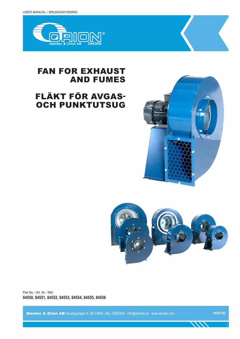
Part No. / Art. Nr. / Réf.: 84550, 84551, 84552, 84553, 84554, 84555, 84556
FAN FOR EXHAUST AND FUMES
FLÄKT FÖR AVGAS- OCH PUNKTUTSUG
105015C
Alentec & Orion AB Grustagsvägen 4, SE-13840, Älta, SWEDEN · [email protected] · www.alentec.com Alentec & Orion AB Grustagsvägen 4, SE-13840, Älta, SWEDEN · [email protected] · www.alentec.com
32
GENERAL / ALLMÄNT / GÉNÉRALITÉSTECHNICAL DATA / TEKNISKA DATA
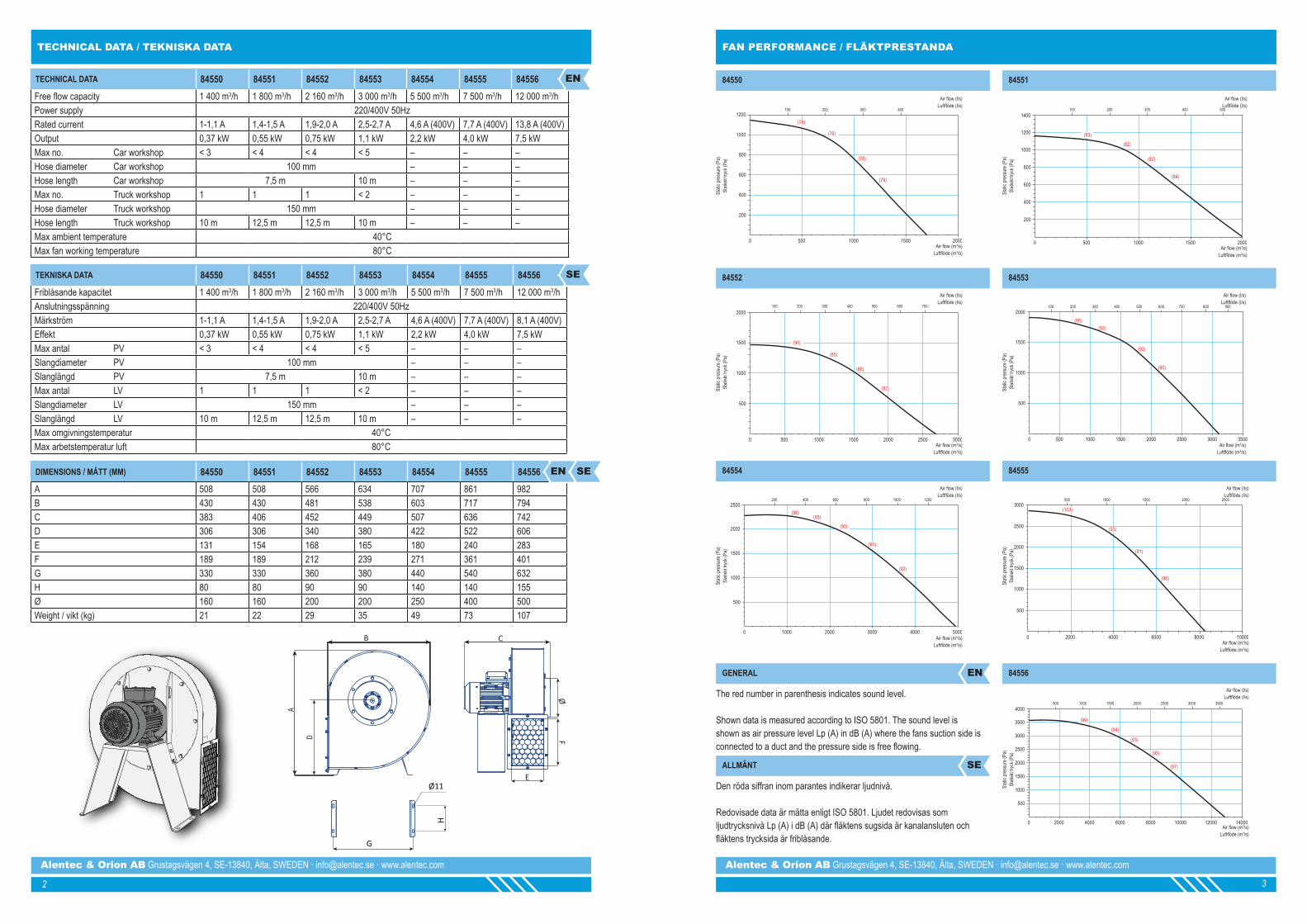
TECHNICAL DATA 84550 84551 84552 84553 84554 84555 84556Free flow capacity 1 400 m3/h 1 800 m3/h 2 160 m3/h 3 000 m3/h 5 500 m3/h 7 500 m3/h 12 000 m3/hPower supply 220/400V 50HzRated current 1-1,1 A 1,4-1,5 A 1,9-2,0 A 2,5-2,7 A 4,6 A (400V) 7,7 A (400V) 13,8 A (400V)Output 0,37 kW 0,55 kW 0,75 kW 1,1 kW 2,2 kW 4,0 kW 7,5 kWMax no. Car workshop < 3 < 4 < 4 < 5 – – –Hose diameter Car workshop 100 mm – – –Hose length Car workshop 7,5 m 10 m – – –Max no. Truck workshop 1 1 1 < 2 – – –Hose diameter Truck workshop 150 mm – – –Hose length Truck workshop 10 m 12,5 m 12,5 m 10 m – – –Max ambient temperature 40°CMax fan working temperature 80°C
TEKNISKA DATA 84550 84551 84552 84553 84554 84555 84556Friblåsande kapacitet 1 400 m3/h 1 800 m3/h 2 160 m3/h 3 000 m3/h 5 500 m3/h 7 500 m3/h 12 000 m3/hAnslutningsspänning 220/400V 50HzMärkström 1-1,1 A 1,4-1,5 A 1,9-2,0 A 2,5-2,7 A 4,6 A (400V) 7,7 A (400V) 8,1 A (400V)Effekt 0,37 kW 0,55 kW 0,75 kW 1,1 kW 2,2 kW 4,0 kW 7,5 kWMax antal PV < 3 < 4 < 4 < 5 – – –Slangdiameter PV 100 mm – – –Slanglängd PV 7,5 m 10 m – – –Max antal LV 1 1 1 < 2 – – –Slangdiameter LV 150 mm – – –Slanglängd LV 10 m 12,5 m 12,5 m 10 m – – –Max omgivningstemperatur 40°CMax arbetstemperatur luft 80°C
DIMENSIONS / MÅTT (MM) 84550 84551 84552 84553 84554 84555 84556A 508 508 566 634 707 861 982B 430 430 481 538 603 717 794C 383 406 452 449 507 636 742D 306 306 340 380 422 522 606E 131 154 168 165 180 240 283F 189 189 212 239 271 361 401G 330 330 360 380 440 540 632H 80 80 90 90 140 140 155Ø 160 160 200 200 250 400 500Weight / vikt (kg) 21 22 29 35 49 73 107
EN
SE
EN SE
FAN PERFORMANCE / FLÄKTPRESTANDA
ØF
E
B
A
C
Ø11
G
H
D
1200
1000
800
600
400
200
500 1000 1500 20000
100 200 300 400
(78)
(76)
(78)
(79)
Air flow (l/s) Luftflöde (l/s)
Air flow (m3/s) Luftflöde (m3/s)
Stati
c pre
ssur
e (Pa
) St
atisk
t tryc
k (Pa
)
1400
1000
800
600
400
200
500 1000 1500 20000
1200
100 200 300 400 500
(83)
(82)
(82)
(84)
Air flow (l/s) Luftflöde (l/s)
Air flow (m3/s) Luftflöde (m3/s)
Stati
c pre
ssur
e (Pa
) St
atisk
t tryc
k (Pa
)
2000
1500
500
500 1500 2000 30000 1000 2500
1000
100 300 400 600200 500 700
(90)
(85)
(85)
(92)
Air flow (l/s) Luftflöde (l/s)
Air flow (m3/s) Luftflöde (m3/s)
Stati
c pre
ssur
e (Pa
) St
atisk
t tryc
k (Pa
)
2000
1500
500
500 1500 2000 35000 1000 2500
1000
3000
100 300 400200 500 600 700 800 900
(93)
(90)
(90)
(95)
Air flow (l/s) Luftflöde (l/s)
Air flow (m3/s) Luftflöde (m3/s)
Stati
c pre
ssur
e (Pa
) St
atisk
t tryc
k (Pa
)
2500
1500
500
2000 50000 1000 3000
1000
4000
2000
400 1000200 600 800 1200
(93)
(90)
(92)
(96)
(90)
Air flow (l/s) Luftflöde (l/s)
Air flow (m3/s) Luftflöde (m3/s)
Stati
c pre
ssur
e (Pa
) St
atisk
t tryc
k (Pa
)
3000
2500
2000
1500
1000
500
2000 4000 6000 80000 10000
500 1000 1500 2000 2500
(103)
(93)
(91)
(96)
Air flow (l/s) Luftflöde (l/s)
Air flow (m3/s) Luftflöde (m3/s)
Stati
c pre
ssur
e (Pa
) St
atisk
t tryc
k (Pa
)
4000
2500
500
6000 140000 2000 8000
1500
12000
3500
4000 10000
1000
2000
3000
1500 3500500 2000 30001000 2500
(94)
(95)
(97)
(99)
(93)
Air flow (l/s) Luftflöde (l/s)
Air flow (m3/s) Luftflöde (m3/s)
Stati
c pre
ssur
e (Pa
) St
atisk
t tryc
k (Pa
)
84550
84552
84554
84553
84555
84556
84551
The red number in parenthesis indicates sound level.
Shown data is measured according to ISO 5801. The sound level is shown as air pressure level Lp (A) in dB (A) where the fans suction side is connected to a duct and the pressure side is free flowing.
Den röda siffran inom parantes indikerar ljudnivå.
Redovisade data är mätta enligt ISO 5801. Ljudet redovisas som ljudtrycksnivå Lp (A) i dB (A) där fläktens sugsida är kanalansluten och fläktens trycksida är friblåsande.
GENERAL
ALLMÄNT
EN
SE

Alentec & Orion AB Grustagsvägen 4, SE-13840, Älta, SWEDEN · [email protected] · www.alentec.com Alentec & Orion AB Grustagsvägen 4, SE-13840, Älta, SWEDEN · [email protected] · www.alentec.com
54
GENERAL / ALLMÄNT / GÉNÉRALITÉSINSTALLATION / INSTALLATIONINSTALLATION / INSTALLATION
The 8455X-series is fan is a radial fan for the evacuation of gases, smoke and low weight particles. The fan series conforms to the protection and safety regulations in the EU's Machinery Directive. The fans boast high levels of quality and operational reliability. ALL fans undergo inspection and test operation before leaving the factory. However, risks can arise with any fan if:
- it is not installed, used or maintained by trained personnel. - it is not used in the intended manner.
WARNING! Please note that electronic equipment is always susceptible to static electricity, high humidity, high temperatures and line failures. The equipment is supplied with high voltage. Use the isolating switch when carrying out service work on the fan.
The fans are not intended for use in the evacuation of explosive gases.
TECHNICAL DESCRIPTION
The fan is delivered in a robust box or on a wooden pallet with the required packaging material. A rating plate is affxed to the motor. The working temperature through the fan is max. 80°C and the ambient temperature between -10° to +40°C. Atmospheric humidity must not exceed 90%. Enclosure class: IP55. Usage type: Continous.
WARNING! The fan's motor generates heat and is fitted with a cooling fan. The inlet to the cooling fan is at the rear of the motor. Do not block the inlet.
FAN INSTALLATION
Installation may only be performed by authorised personnel with regard to these installation instructions and applicable regulations. Make sure that all safety-related fan components satisfy their function. The stability of the fan must always be ensured during operation. In order to achieve optimum function, it is important for the fan's duct connections to be correctly executed. Incorrect installation can cause considerable deterioration in the fan's performance with regard to pressure drop and sound levels.
In order to achieve optimum performance, we recommend that the inlet connection is a straight duct that is 5 times the diameter of the duct. If an outlet duct is used, the same applies to this. If the system requires a 90° bend in the outlet, it should deviate in the impeller's direction of rotation (see below) should be fitted.
WARNING! There is always a risk of clothes or loose items being sucked into a free-blowing fan. This can cause personal injury or damage to property.
The fan is supplied with the outlet pointing as illustrated on page 2. If an alternative outlet air direction is required, the fan housing can be set in 8 possible positions. Take great care to ensure that the impeller is not damaged when reinstalling the fan housing.
In the event of outdoor installation, a drainage hole must be drilled at what becomes the lowest point in the installed fan, according to the selected outlet direction.
WARNING! In the case of professional installation, too, fans can produce harmful noise levels. It should also be noted that specified noise data (see separate product sheet) can be altered by the surroundings or resonance in the operating location.
WARNING! The fans are designed for installation in systems and therefore have no guard on the inlet. This means that the fan must not be started until it is connected to a duct. The guard installed on the outlet can be removed if you want to connect an outlet duct (see accessories on page 8).
WALLMOUNT OUTDOOR INSTALLATION
Under no circumstances mount the fan in this position. This can cause serious damage to the fans bearings.
A flexible installation that optimises the pressure drop on the inlet side. Makes it possible to choose outlet direction. In the event of condensation problems, installation as illustrated is recommended. If noise levels are the priority, it is recommended to have the outlet pointing straight up, with drainage in the fan housing (for drainage see above).
Note! The fan bracket must be made on site.
An installation that is used when low noise levels are prioritised. The disadvantage of this arrangement is that the fan is located high up if the extract air duct is high.
Note! The fan housing needs to be drained (for drainage see above).
8455X-serien är en radialfläkt för evakuering av gaser, rök och lättare partiklar. Fläktserien följer skydds- och säkerhetsföreskrifterna i EUs maskindirektiv. Fläktarna har en hög driftsäkerhet och en hög kvalitet. Samtliga fläktar genomgår kontroll och provkörning innan de lämnar fabrik. Risker kan dock uppstå med en fläkt om:
-den inte installeras, används och underhålls av utbildad personal. -den inte används på ett för fläkten avsett sätt.
VARNING! Notera att elektronisk utrustning alltid är känslig för statisk elektricitet, hög luftfuktighet, hög temperatur och nätstörningar. Utrustningen är matad med högspänning. Använd arbetsbrytare vid servicearbeten på fläkten.
Fläktarna är inte avsedda att användas vid evakuering av explosiva gaser.
TEKNISK BESKRIVNING
Fläkten levereras i robust kartong eller på träpall med erfoderligt packmaterial. En märkskylt är placerad på motorn. Arbetstemperaturen genom fläkten är max 80°C och omgivningstemperatur mellan -10° till +40°C. Luftfuktigheten får ej överstiga 90%. Kapslingsklass. IP55. Användningstyp: Kontinuerlig. VARNING! Fläktens motor alstrar värme och är försedd med kylfläkt. Inloppet till kylfläkten finns baktill på motorn. Blockera ej inloppet.
INSTALLATION AV FLÄKT
Monteringen får bara utföras av behörig personal under beaktande av denna montageanvisning och gällande föreskrifter. Säkerställ att alla säkerhetsrelaterade fläktkomponenter uppfyller sin funktion. Fläktens stabilitet måste alltid vara tillgodosedd under drift. För att erhålla optimal funktion är det viktigt att fläktens kanalanslutningar är korrekt utförda. Felaktig installation kan orsaka stora försämringar av fläktens prestanda, i avseende på tryckfall och ljud.
För att erhålla optimal prestanda rekommenderar vi att inloppsanslutningen är en rak kanal som är 5 ggr. kanalens diameter. Om utloppskanal används gäller samma sak för den. Kräver anläggningen en 90° krök på utloppet, bör den vika av i fläkthjulets rotationsriktning (se nedan).
VARNING! Det finns alltid en risk för att kläder eller lösa före- mål sugs in i en friblåsande fläkt. Detta kan orsaka skador på person eller egendom.
Fläkten levereras med utloppet riktat enligt bild på sida 2. Om alternativ utblåsriktning önskas kan fläkt-huset riktas i 8 möjliga lägen. Beakta stor försiktighet så att inte fläkthjul skadas vid återmontage av fläkthus
Vid utomhusmontage måste, efter vald utblåsriktning, ett dräneringshål borras i det som blir lägsta punkten på den färdigmonterade fläkten.
VARNING! Även vid fackmannamässig installation kan fläktar ge ifrån sig skadliga ljudnivåer. Man bör också observera att angivna ljuddata (se separat produktblad) kan förändras av omgivning eller resonans på driftplats.
VARNING! Fläktarna är konstruerade för montering i anläggningar och har därför inget beröringsskydd på in- loppet. Detta medför att fläkten inte får startas innan den är ansluten mot kanal. Det på utloppet monterade beröringsskyddet är demonterbart om man önskar ansluta utloppskanal (se tillbehör sid 8).
VÄGGMONTAGE UTOMHUS
Montera under inga omständigheter fläkten på detta viset. Detta kan orsaka allvarliga skador på fläktens lager.
En flexibel montering som optimerar tryckfall på inloppssidan. Möjliggör val av utloppsriktning. Vid kondensproblem rekomenderas montering enligt skiss. Prioriteras ljudnivå rekomenderas utlopp rakt upp, med dränering i fläkthus (För dränering se sid. 3).
OBS! Fläktkonsol måste platsbyggas.
En montering som används när låga ljudnivåer prioriteras. Nackdel är att fläkten hamnar högt om frånluftskanalen är hög. OBS! Dränering av fläkthus krävs (För dränering se ovan).
GENERAL INSTALLATION, CONT.ALLMÄNT INSTALLATION, FORTS.EN ENSE SE

Alentec & Orion AB Grustagsvägen 4, SE-13840, Älta, SWEDEN · [email protected] · www.alentec.com Alentec & Orion AB Grustagsvägen 4, SE-13840, Älta, SWEDEN · [email protected] · www.alentec.com
76
INSTALLATION / INSTALLATIONINSTALLATION / INSTALLATION
ROOF INSTALLATION OUTDOORS
A low-level, sideways outlet direction is suitable in the event of condensation problems.
Note! The base must be made on site due to possible snow.
Upwards outlet direction, suitable in the event of noise problems.
Note! Drainage is required (for drainage see page 5).
A high-level, sideways outlet direction is suitable when condensation is not a problem.
Note! Drainage is required (for drainage see page 5).
ELECTRIC INSTALLATION
The equipment is supplied with high voltage and must always be fitted with a safety switch for carrying out servicing work in connection with the fan.
The choice of cable and cable cross-section must comply with the national requirements that apply to fixed installations.
ELECTRIC INSTALLATION
In order to satisfy applicable standards, the fan must be fitted with a contactor and overcurrent protection.
If technical regulating apparatus (e.g. frequency converter) is used, the manufacturer's recommendations for avoiding interference must be observed. E.g. EMC, protective earth, cable length, cable shielding, etc..
§ TAKMONTAGE UTOMHUS
Låg sidoriktad utblåsriktning lämpar sig vid kondensproblem.
OBS! Fundament måste platsbyggas för ev. snö.
Uppåtriktad utblåsriktning, lämpar sig vid ljudproblem.
OBS! Kräver dränering (För dränering se sid. 5).
Hög sidoriktad utblåsriktning, lämpar sig när kondens inte är ett problem.
OBS! Kräver dränering (För dränering se sid. 5).
ELEKTRISK INSTALLATION
Utrustningen är matad med högspänning och skall alltid vara försedd med säkerhetsbrytare för servicearbeten i anslutning till fläkten.
Val av kabel och kabelarea skall följa de nationella krav som gäller för fasta installationer.
§ ELEKTRISK INSTALLATION
För att uppfylla gällande normer skall fläkten vara försedd med kontaktor och överströmsskydd.
Om reglertekniska apparater (ex. frekvensomvandlare) används skall tillverkarens rekommendationer för att undvika störningar beaktas. Exempelvis EMC, skyddsjord, kabellängd, kabelavskärmning etc.
Single phase fans are supplied with the motors connected for clockwise rotation. The speed of the single phase motors CANNOT be regulated.
Clockwise rotation Counter Clockwise rotation
Enfasfläktarna levereras med motorerna kopplade för medsols rotation. Varvtalet på enfasmotorerna kan INTE regleras.
Medsols rotation Motsols rotation
Three-phase fans are supplied with the motor connected for 400V (Y-connection).
D-connection Y-connection
Trefasfläktarna levereras med motorn kopplad för 400V (Y-koppling)
D-koppling Y-koppling
Our fans have been designed for continuous use for an extended time with a high level of reliability. Like all machines, regular servicing and maintenance are required to achieve optimum function.
Alentec & Orion AB recommends the following maintenance schedule:
Våra fläktar har utformats för kontinuerlig använd-ning under lång tid och med stor tillförlitlighet. Liksom alla maskiner, krävs regelbunden service och under-håll för att uppnå optimal funktion.
Alentec & Orion AB rekommenderar följande underhållsschema:
MAINTENANCE UNDERHÅLLEN SE
COMPONENT INTERVAL: 6 MONTHS
Motor Check function. Replace motor if necessary.
ImpellerCheck for any damage and clear away foreign objects if necessary. Replace impeller in the event of damage.
Fan housingCheck that connections are secure and clear away foreign objects. Check the drainage hole and clear if necessary.
KOMPONENT INTERVALL: 6 MÅNADER
Motor Kontrollera funktion. Byt motor vid behov.
Fläkthjul Kontrollera eventuella skador och rensa bort främ-mande föremål vid behov. Byt fläkthjul vid skada.
FläkthusKontrollera att anslutningar sitter fast samt rensa bort främmande föremål. Kontrollera dräneringshål och rensa vid behov.

Alentec & Orion AB Grustagsvägen 4, SE-13840, Älta, SWEDEN · [email protected] · www.alentec.com Alentec & Orion AB Grustagsvägen 4, SE-13840, Älta, SWEDEN · [email protected] · www.alentec.com
98
GENERAL / ALLMÄNT / GÉNÉRALITÉSTROUBLESHOOTING / FELSÖKNING
SYMPTOM POSSIBLE FAULT SOLUTION
The fan has stopped
Fault in the power supply. Check the power supply.
Short circuit in connection. Check for moistrure in the safety switch and motor connection.
Locked impeller.
Check that there are no foreign objects in the fan housing.
Checked that no ice has formed in the fan housing.
Check that the bearings in the motor is working.
Loss of performance
Motor winding. Check the resistance between windings.
Debris Check that there are no foreign objects in the fan housing.
Incorrect direction of rotation. Check the direction of rotation.
Connections. Check that the connections and duct routing are correct.
SYMPTOM POSSIBLE FAULT SOLUTION
Fläkt har stannat.
Fel på strömförsörjningen. Kontrollera strömförsörjning.
Kortslutning i anslutning. Kontrollera fukt i säkerhetsbrytare och motoranslutning.
Låst fläkthjul.
Kontrollera att främmande föremål ej förekommer i fläkthuset.
Kontrollera att is ej har bildats i fläkthus.
Kontrollera att lagring i motor fungerar.
Prestandaförlust.
Motorlindning. Kontrollera motstånd mellan lindningar.
Skräp Kontrollera att främmande föremål ej förekommer i fläkthuset.
Fel rotationsriktning. Kontrollera rotationsriktningen.
Anslutningar. Kontrollera att anslutningar och kanaldragning är korrekt.
EN
SE
EXPLODED VIEW / SPRÄNGSKISS
PARTS LIST DELLISTA POS.Bracket Konsol 1Motor Motor 2Motor plate Motorplåt 3Impeller Fläkthjul 4Fan housing Fläkthus 5Inlet Inlopp 6Outlet grating Utloppsgaller 7Bolt Skruv 1aWasher Bricka 1bNut Mutter 1cBolt Skruv 2aWasher Bricka 2bNut Mutter 2cBolt Skruv 3aWasher Bricka 3bRivet nut Nitmutter 3cBolt Skruv 4aWasher Bricka 4bBolt Mutter 6aWasher Bricka 6bRivet nut Nitmutter 6cCarriage bolt Vagnsmutter 7aWasher Bricka 7bNut Mutter 7c
1
2
34
5
6
7
1 a,b,c
2 a,b,c
7 a,b,c
6 a,b,c
4 a,b
3 a,b, c
EN SE
ACCESSORIES / TILLBEHÖR EN SE
PART NO. ITEM NAME BESKRIVNING FOR FAN/ FÖR FLÄKT
84571 Outlet from rectangular to round Ø250mm Utlopp från rektangulär till rund Ø250mm 8455484572 Outlet from rectangular to round Ø400mm Utlopp från rektangulär till rund Ø400mm 8455584573 Outlet from rectangular to round Ø500mm Utlopp från rektangulär till rund Ø500mm 8455684384
Soft connection for noise and vibration free connection
Ø160mm
Mjuk anslutning för vibrationsdämpning
Ø160mm –84385 Ø200mm Ø200mm –84386 Ø250mm Ø250mm –84387 Ø315mm Ø315mm –84388 Ø400mm Ø400mm –84389 Ø500mm Ø500mm –85890 Anti vibration dampers Vibrationsdämpningsfötter 84554, 8455585391 Anti vibration dampers Vibrationsdämpningsfötter 84556

Alentec & Orion AB Grustagsvägen 4, SE-13840, Älta, SWEDEN · [email protected] · www.alentec.com
10
EC CONFORMITY DECLARATION / KONFORMITETSDEKLARATION
Krister TynhageManaging Director
Mikael TheorinTechnical Director
105015CAlentec & Orion AB Grustagsvägen 4, SE-13840, Älta, SWEDEN · [email protected] · www.alentec.com
Krister Tynhage Mikael Theorin Alentec & Orion AB Grustagsvägen 4 138 40 ÄLTA
Herewith declares that the fan models 84550, 84551, 84552, 84553, 84554, 84555 and 84556 is in conformity with all relevant provisions of ordinances in directives and standards below.
Machinery directive 2006/42/EC
EMC-Directive 2014/30/EU
The declaration is only valid if installation of the product is made in accordence to Alentec & Orion AB instructions and provided that no changes has been made on the product.
Försäkran gäller endast om installation av produkten skett enligt Alentec & Orion ABs instruktioner och förutsatt att inga ändringar gjorts på produkten.
EN ISO 12100:2010
EN 60204-1
Maskindirektivet 2006/42/EG
EMC-Direktivet 2014/30/EU
Försäkrar härmed att fläktmodellerna 84550, 84551, 84552, 84553, 84554, 84555 och 84556 överensstämmer med alla tillämpliga bestämmelser i direktiv och standarder enligt nedan.
AUTHORISED PERSON / BEHÖRIG PERSON EN SE
DIRECTIVES / DIREKTIV EN SE
STANDARDS / STANDARDER EN SE
OTHER / ÖVRIGT EN SE
Älta 2015-03-26 Älta 2015-03-26


