
Factors affecting mechanical properties ofresistance spot welds
M. Pouranvari*1 and S. P. H. Marashi2
The present paper addresses the factors governing the mechanical performance of low carbon
resistance spot welds. Correlations among the process parameters (welding current, welding
time, electrode force and holding time), physical spot weld attributes and mechanical
performance are analysed. Peak load and energy absorption of spot welds during the tensile
shear test are used to describe spot welds performance. It is shown that weld nugget size,
electrode indentation, failure mode and strength/ductility of the failure location are the main
factors affecting peak load and energy absorption of spot welds.
Keywords: Resistance spot welding, Failure mode, Peak load, Energy absorption, Expulsion, Weld nugget size
IntroductionVehicle crashworthiness, which is defined as the capa-bility of a car structure to provide adequate protection toits passengers against injuries in the event of a crash,largely depends on the integrity and mechanical perfor-mance of spot welds.1 Resistance spot welding is thedominant process in sheet metal joining. To ensure andmaintain the structural integrity of automotive bodystructure under service condition such as a crashsituation, the remotest possibility of producing even oneor two defective welds in a critical component needs to beeliminated.2 Therefore, evaluation of spot weld quality isa vital issue for the reliability of the vehicle and forimproving the economics of vehicle production. Evalu-ating spot welds quality requires studying welding processvariables and weld performance interrelations.
Weld performance characterisations normally refer tostatic and dynamic strength. The tensile shear test is themost usual test for evaluating spot weld mechanicalbehaviour under static condition both because of itssimplicity and the fact that many of the spot weldedstructures are designed to bear tensile shear loads. Mostresearchers have used peak load to describe spot weldmechanical behaviour. However, as Zhou et al.3
suggested, energy absorption corresponding to peakload should be used to describe spot weld mechanicalbehaviour, more precisely. The higher the energyabsorption, the higher is the weld reliability underimpact conditions such as accidents.4
The present paper aims at investigating the effect ofwelding parameters including welding current, weldingtime, electrode force and holding time on the weldnugget size (WNS), failure mode, peak load and energyabsorption of low carbon resistance spot welded sheets.
Factors affecting peak load and energy absorption ofspot weld are highlighted and analysed.
Experimental procedureA 0?8 mm thick uncoated low carbon steel of the typeused in automotive industry (st12) was used in thisinvestigation. Chemical composition of the steel is Fe–0?045C 0?032Si–0?189Mn.
Welds were made using a 120 kVA AC resistance spotwelding machine with constant current control operat-ing at 50 Hz. Welding was conducted using a 45utruncated cone RWMA Class 2 electrode with 5 mmface diameter. Several welding schedules were used toinvestigate the effect of process parameter on themechanical performance, as follows:
(i) at two constant levels of welding time tw, 0?14 and0?18 s, the welding current was changed from 7 to11 kA
(ii) at two constant levels of welding current Iw, 7and 8 kA, the tw was changed from 0?12 to0?18 s
(iii) electrode force was changed from 2?8 to 4?5 kNupon an Iw of 8 kA, tw of 0?16 s and holding timeof 0?1 s
(iv) holding time th was changed from 0?1 to 1?8 supon an Iw of 8 kA, welding time of 0?16 s andelectrode force of 3?4 kN.
Three samples were performed per welding conditionincluding two samples for tensile shear test and onesample for metallographic investigation.
The shear tensile test samples were prepared accord-ing to ANSI/AWS/SAE/D8?9-97 standard.5 Samples of145645 mm were sheared and a single spot weld wasmade at the centre of an overlapped area of 45 mm. Thetensile shear tests were performed employing an Instronuniversal testing machine with 2 mm min21 strain rate.Peak load (measured as the peak point in the load–displacement curve) and failure energy (measured asthe area under the load–displacement curve up to thepeak load) were determined from the load–displacement
1Materials and Metallurgical Engineering Department, School ofEngineering, Islamic Azad University, Dezful Branch, Dezful, Iran2Mining and Metallurgical Engineering Department, Amirkabir University ofTechnology, Tehran, Iran
*Corresponding author, email [email protected]
� 2010 Institute of Materials, Minerals and MiningPublished by Maney on behalf of the InstituteReceived 11 March 2009; accepted 5 May 2009DOI 10.1179/174328409X459301 Materials Science and Technology 2010 VOL 26 NO 9 1137

curve. The data points for peak load and failure energyare average of two specimens.
Nugget diameter and average electrode indentationwere measured for all of the samples. Failure mode wasdetermined from the failed samples. Cross-sections ofspot welded joints were used for microstructuralinvestigations. Microstructural studies were carried outusing an optical microscope. Microhardness test wasperformed along interfacial line and 100 mm above theweld centreline using 100 g load.
Results
Spot weld structure and hardness profileRapid heating and cooling during resistance spotwelding induces microstructural changes in the jointregion. Figure 1a shows a typical macrostructure of alow carbon resistance spot weld indicating three distinctzones in the joint:
(i) fusion zone or so called weld nugget (WN)(ii) heat affected zone (HAZ)
(iii) base metal (BM).
Figure 1b shows the microstructure of the WN, whichmainly consists of martensite. Despite the low carboncontent of the BM and its ferritic structure, martensitephase was formed due to the high cooling rate ofresistance spot welds (RSW) process. Weld nuggetmicrostructure of low carbon steel RSWs depends onthe chemical composition of the sheet and the coolingrate. Gould et al.6 proposed a simple analytical modelpredicting cooling rate during resistance spot welding.According to this model, cooling rate for 0?8 mmthickness is ,8000 K s21. Presence of water cooledcopper electrodes and their quenching effect as well asshort welding cycle can explain high cooling rates ofRSW process. Figure 1c shows a typical hardness profileof the joint indicating three distinct zones correspondingto WN, HAZ and BM. The value of weld nuggethardness is about two times higher than that of the BM,due to the martensite formation in this zone.
In addition to the microstructural changes, spotwelding process introduces geometrical changes in thejoint location. Spot welding induces a natural notch attwo sheet metals joint spot (Fig. 1a), which affects itsmechanical behaviour. Electrode force creates indenta-tion (Fig. 1a), which in turn produces stress concentra-tion locations at the indentation edges.
Effect of welding parameters on quality of spotweldsGenerally, industrial standards recommend a minimumWNS and a minimum strength for spot welds.5,7,8 In thissection, the results of the effect of the weldingparameters on WNS, peak load and energy absorptionare presented.
Figures 2 and 3 show the effects of Iw and tw on WNS,peak load and energy absorption. According to Figs. 2and 3 the following points can be drawn:
(i) increasing Iw and tw increases the WNS.However, at high welding time, increasing Iw
beyond 9 kA and at high welding currents,increasing tw beyond 0?2 s does not have apronounced effect on the WNS
(ii) increasing Iw and tw increase the peak load.However, under high heat input welding condi-tion (i.e. high welding current and welding time),peak load is nearly independent from the heatinput
(iii) increasing Iw and tw also increase the energyabsorption. However, under high heat inputwelding condition, energy absorption is reduced.For example, at a constant WNS of 5 mm,increasing Iw from 10 to 12 kA at constant tw of0?18 s results in the reduction of the energyabsorption. In these cases, severe expulsion wasobserved.
Table 1 presents the comparison between the mechan-ical properties of spot welds with expulsion and withoutexpulsion. At a nearly constant WNS, spot welds withexpulsion exhibit lower energy absorption. However,expulsion dose not have a significant effect on the peakload. Electrode indentation is more pronounced for spotweld exhibiting expulsion.
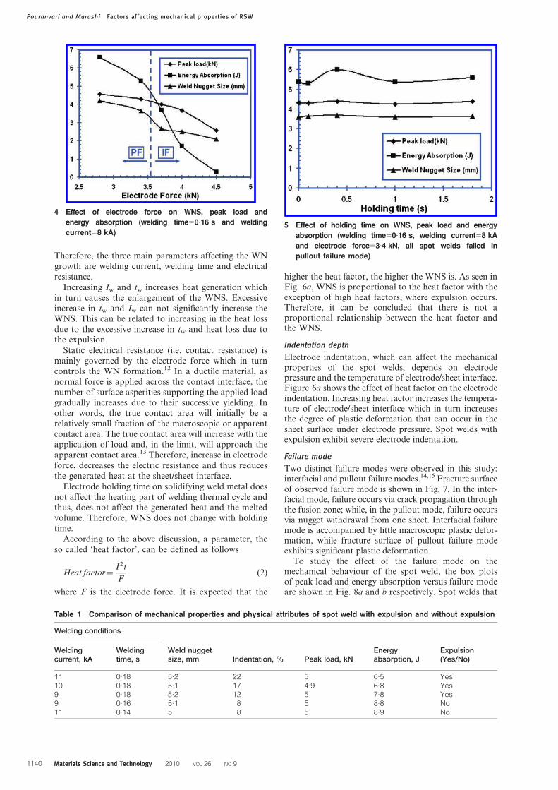
Figure 4 shows that increasing the electrode forceleads to significant decrease in the WNS, peak load andenergy absorption.
1 a typical macrostructure, b BM microstructure, c WN
microstructure and d hardness profile for spot welds
(holding time is 0?1 s)
Pouranvari and Marashi Factors affecting mechanical properties of RSW
1138 Materials Science and Technology 2010 VOL 26 NO 9

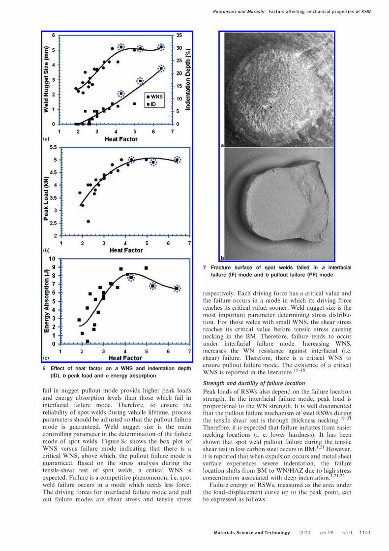
Figure 5 shows that th dose not have a significanteffect on the WNS, peak load and energy absorption.
Discussion
Factors controlling peak load and energyabsorptionLoad bearing capacity and energy absorption capabilityof spot welds depend on the following factors.
Weld nugget size
Weld nugget size is the most important parametergoverning the mechanical properties of the spot welds.9–11
It determines the overall bonding area of the joint, and
is controlled by heat input rate which in turns is governedby the welding parameters. Generated heat duringresistance spot welding can be expressed as follows
Q~RI2t (1)
where Q, R, I and t are generated heat, electrical resis-tance, welding current and welding time respectively.
3 Effect of welding time on a WNS, b peak load and
c energy absorption (holding time50?1 s, electrode
force53?4 kN)
2 Effect of welding current on a WNS, b peak load and
c) energy absorption (holding time50?1 s, electrode
force53?4 kN)
Pouranvari and Marashi Factors affecting mechanical properties of RSW
Materials Science and Technology 2010 VOL 26 NO 9 1139
Therefore, the three main parameters affecting the WNgrowth are welding current, welding time and electricalresistance.
Increasing Iw and tw increases heat generation whichin turn causes the enlargement of the WNS. Excessiveincrease in tw and Iw can not significantly increase theWNS. This can be related to increasing in the heat lossdue to the excessive increase in tw and heat loss due tothe expulsion.
Static electrical resistance (i.e. contact resistance) ismainly governed by the electrode force which in turncontrols the WN formation.12 In a ductile material, asnormal force is applied across the contact interface, thenumber of surface asperities supporting the applied loadgradually increases due to their successive yielding. Inother words, the true contact area will initially be arelatively small fraction of the macroscopic or apparentcontact area. The true contact area will increase with theapplication of load and, in the limit, will approach theapparent contact area.13 Therefore, increase in electrodeforce, decreases the electric resistance and thus reducesthe generated heat at the sheet/sheet interface.
Electrode holding time on solidifying weld metal doesnot affect the heating part of welding thermal cycle andthus, does not affect the generated heat and the meltedvolume. Therefore, WNS does not change with holdingtime.
According to the above discussion, a parameter, theso called ‘heat factor’, can be defined as follows
Heat factor~I2t
F(2)
where F is the electrode force. It is expected that the
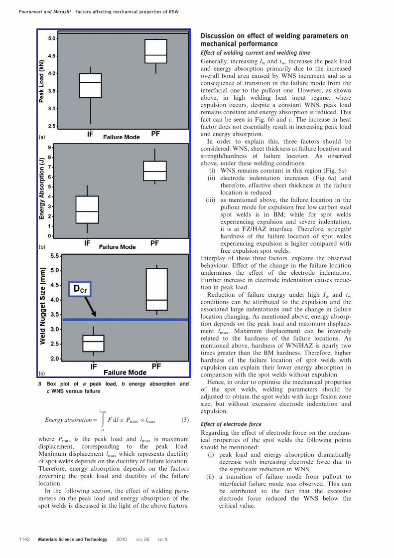
higher the heat factor, the higher the WNS is. As seen inFig. 6a, WNS is proportional to the heat factor with theexception of high heat factors, where expulsion occurs.Therefore, it can be concluded that there is not aproportional relationship between the heat factor andthe WNS.
Indentation depth
Electrode indentation, which can affect the mechanicalproperties of the spot welds, depends on electrodepressure and the temperature of electrode/sheet interface.Figure 6a shows the effect of heat factor on the electrodeindentation. Increasing heat factor increases the tempera-ture of electrode/sheet interface which in turn increasesthe degree of plastic deformation that can occur in thesheet surface under electrode pressure. Spot welds withexpulsion exhibit severe electrode indentation.
Failure mode
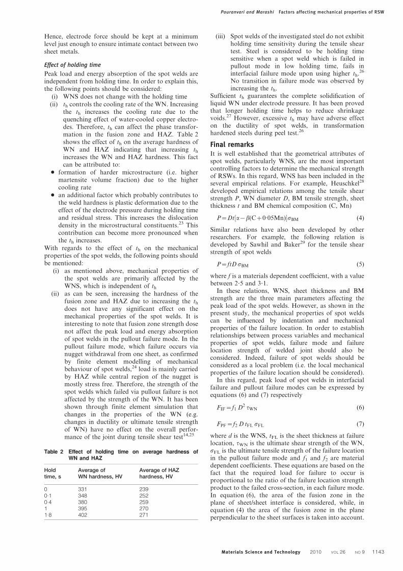
Two distinct failure modes were observed in this study:interfacial and pullout failure modes.14,15 Fracture surfaceof observed failure mode is shown in Fig. 7. In the inter-facial mode, failure occurs via crack propagation throughthe fusion zone; while, in the pullout mode, failure occursvia nugget withdrawal from one sheet. Interfacial failuremode is accompanied by little macroscopic plastic defor-mation, while fracture surface of pullout failure modeexhibits significant plastic deformation.
To study the effect of the failure mode on themechanical behaviour of the spot weld, the box plotsof peak load and energy absorption versus failure modeare shown in Fig. 8a and b respectively. Spot welds that
Table 1 Comparison of mechanical properties and physical attributes of spot weld with expulsion and without expulsion
Welding conditions
Weld nuggetsize, mm Indentation, % Peak load, kN
Energyabsorption, J
Expulsion(Yes/No)
Weldingcurrent, kA
Weldingtime, s
11 0.18 5.2 22 5 6.5 Yes10 0.18 5.1 17 4.9 6.8 Yes9 0.18 5.2 12 5 7.8 Yes9 0.16 5.1 8 5 8.8 No11 0.14 5 8 5 8.9 No
4 Effect of electrode force on WNS, peak load and
energy absorption (welding time50?16 s and welding
current58 kA)5 Effect of holding time on WNS, peak load and energy
absorption (welding time50?16 s, welding current58 kA
and electrode force53?4 kN, all spot welds failed in
pullout failure mode)
Pouranvari and Marashi Factors affecting mechanical properties of RSW
1140 Materials Science and Technology 2010 VOL 26 NO 9
fail in nugget pullout mode provide higher peak loadsand energy absorption levels than those which fail ininterfacial failure mode. Therefore, to ensure thereliability of spot welds during vehicle lifetime, processparameters should be adjusted so that the pullout failuremode is guaranteed. Weld nugget size is the maincontrolling parameter in the determination of the failuremode of spot welds. Figure 8c shows the box plot ofWNS versus failure mode indicating that there is acritical WNS, above which, the pullout failure mode isguaranteed. Based on the stress analysis during thetensile-shear test of spot welds, a critical WNS isexpected. Failure is a competitive phenomenon, i.e. spotweld failure occurs in a mode which needs less force.The driving forces for interfacial failure mode and pullout failure modes are shear stress and tensile stress
respectively. Each driving force has a critical value andthe failure occurs in a mode in which its driving forcereaches its critical value, sooner. Weld nugget size is themost important parameter determining stress distribu-tion. For those welds with small WNS, the shear stressreaches its critical value before tensile stress causingnecking in the BM. Therefore, failure tends to occurunder interfacial failure mode. Increasing WNS,increases the WN resistance against interfacial (i.e.shear) failure. Therefore, there is a critical WNS toensure pullout failure mode. The existence of a criticalWNS is reported in the literature.15–18
Strength and ductility of failure location
Peak loads of RSWs also depend on the failure locationstrength. In the interfacial failure mode, peak load isproportional to the WN strength. It is well documentedthat the pullout failure mechanism of steel RSWs duringthe tensile shear test is through thickness necking.19–21
Therefore, it is expected that failure initiates from easiernecking locations (i. e. lower hardness). It has beenshown that spot weld pullout failure during the tensileshear test in low carbon steel occurs in BM.1,21 However,it is reported that when expulsion occurs and metal sheetsurface experiences severe indentation, the failurelocation shifts from BM to WN/HAZ due to high stressconcentration associated with deep indentation.1,21,22
Failure energy of RSWs, measured as the area underthe load–displacement curve up to the peak point, canbe expressed as follows
6 Effect of heat factor on a WNS and indentation depth
(ID), b peak load and c energy absorption
7 Fracture surface of spot welds failed in a interfacial
failure (IF) mode and b pullout failure (PF) mode
Pouranvari and Marashi Factors affecting mechanical properties of RSW
Materials Science and Technology 2010 VOL 26 NO 9 1141
Energy absorption~
ðlmax
o
F dl!Pmax |lmax (3)
where Pmax is the peak load and lmax is maximumdisplacement, corresponding to the peak load.Maximum displacement lmax which represents ductilityof spot welds depends on the ductility of failure location.Therefore, energy absorption depends on the factorsgoverning the peak load and ductility of the failurelocation.
In the following section, the effect of welding para-meters on the peak load and energy absorption of thespot welds is discussed in the light of the above factors.
Discussion on effect of welding parameters onmechanical performanceEffect of welding current and welding time
Generally, increasing Iw and tw, increases the peak loadand energy absorption primarily due to the increasedoverall bond area caused by WNS increment and as aconsequence of transition in the failure mode from theinterfacial one to the pullout one. However, as shownabove, in high welding heat input regime, whereexpulsion occurs, despite a constant WNS, peak loadremains constant and energy absorption is reduced. Thisfact can be seen in Fig. 6b and c. The increase in heatfactor does not essentially result in increasing peak loadand energy absorption.
In order to explain this, three factors should beconsidered: WNS, sheet thickness at failure location andstrength/hardness of failure location. As observedabove, under these welding conditions:
(i) WNS remains constant in this region (Fig. 6a)(ii) electrode indentation increases (Fig. 6a) and
therefore, effective sheet thickness at the failurelocation is reduced
(iii) as mentioned above, the failure location in thepullout mode for expulsion free low carbon steelspot welds is in BM; while for spot weldsexperiencing expulsion and severe indentation,it is at FZ/HAZ interface. Therefore, strength/hardness of the failure location of spot weldsexperiencing expulsion is higher compared withfree expulsion spot welds.
Interplay of these three factors, explains the observedbehaviour. Effect of the change in the failure locationundermines the effect of the electrode indentation.Further increase in electrode indentation causes reduc-tion in peak load.
Reduction of failure energy under high Iw and tw
conditions can be attributed to the expulsion and theassociated large indentations and the change in failurelocation changing. As mentioned above, energy absorp-tion depends on the peak load and maximum displace-ment lmax. Maximum displacement can be inverselyrelated to the hardness of the failure locations. Asmentioned above, hardness of WN/HAZ is nearly twotimes greater than the BM hardness. Therefore, higherhardness of the failure location of spot welds withexpulsion can explain their lower energy absorption incomparison with the spot welds without expulsion.
Hence, in order to optimise the mechanical propertiesof the spot welds, welding parameters should beadjusted to obtain the spot welds with large fusion zonesize, but without excessive electrode indentation andexpulsion.
Effect of electrode force
Regarding the effect of electrode force on the mechan-ical properties of the spot welds the following pointsshould be mentioned:
(i) peak load and energy absorption dramaticallydecrease with increasing electrode force due tothe significant reduction in WNS
(ii) a transition of failure mode from pullout tointerfacial failure mode was observed. This canbe attributed to the fact that the excessiveelectrode force reduced the WNS below thecritical value.
8 Box plot of a peak load, b energy absorption and
c WNS versus failure
Pouranvari and Marashi Factors affecting mechanical properties of RSW
1142 Materials Science and Technology 2010 VOL 26 NO 9
Hence, electrode force should be kept at a minimumlevel just enough to ensure intimate contact between twosheet metals.
Effect of holding time
Peak load and energy absorption of the spot welds areindependent from holding time. In order to explain this,the following points should be considered:
(i) WNS does not change with the holding time
(ii) th controls the cooling rate of the WN. Increasingthe th increases the cooling rate due to thequenching effect of water-cooled copper electro-des. Therefore, th can affect the phase transfor-mation in the fusion zone and HAZ. Table 2shows the effect of th on the average hardness ofWN and HAZ indicating that increasing th
increases the WN and HAZ hardness. This factcan be attributed to:
N formation of harder microstructure (i.e. highermartensite volume fraction) due to the highercooling rate
N an additional factor which probably contributes tothe weld hardness is plastic deformation due to theeffect of the electrode pressure during holding timeand residual stress. This increases the dislocationdensity in the microstructural constituents.23 Thiscontribution can become more pronounced whenthe th increases.
With regards to the effect of th on the mechanicalproperties of the spot welds, the following points shouldbe mentioned:
(i) as mentioned above, mechanical properties ofthe spot welds are primarily affected by theWNS, which is independent of th
(ii) as can be seen, increasing the hardness of thefusion zone and HAZ due to increasing the th
does not have any significant effect on themechanical properties of the spot welds. It isinteresting to note that fusion zone strength dosenot affect the peak load and energy absorptionof spot welds in the pullout failure mode. In thepullout failure mode, which failure occurs vianugget withdrawal from one sheet, as confirmedby finite element modelling of mechanicalbehaviour of spot welds,24 load is mainly carriedby HAZ while central region of the nugget ismostly stress free. Therefore, the strength of thespot welds which failed via pullout failure is notaffected by the strength of the WN. It has beenshown through finite element simulation thatchanges in the properties of the WN (e.g.changes in ductility or ultimate tensile strengthof WN) have no effect on the overall perfor-mance of the joint during tensile shear test14,25
(iii) Spot welds of the investigated steel do not exhibitholding time sensitivity during the tensile sheartest. Steel is considered to be holding timesensitive when a spot weld which is failed inpullout mode in low holding time, fails ininterfacial failure mode upon using higher th.26
No transition in failure mode was observed byincreasing the th.
Sufficient th guarantees the complete solidification ofliquid WN under electrode pressure. It has been provedthat longer holding time helps to reduce shrinkagevoids.27 However, excessive th may have adverse effecton the ductility of spot welds, in transformationhardened steels during peel test.26
Final remarksIt is well established that the geometrical attributes ofspot welds, particularly WNS, are the most importantcontrolling factors to determine the mechanical strengthof RSWs. In this regard, WNS has been included in theseveral empirical relations. For example, Heuschkel28
developed empirical relations among the tensile shearstrength P, WN diameter D, BM tensile strength, sheetthickness t and BM chemical composition (C, Mn)
P~Dt a{b(Cz0:05Mn)½ �sBM (4)
Similar relations have also been developed by otherresearchers. For example, the following relation isdeveloped by Sawhil and Baker29 for the tensile shearstrength of spot welds
P~ftD sBM (5)
where f is a materials dependent coefficient, with a valuebetween 2?5 and 3?1.
In these relations, WNS, sheet thickness and BMstrength are the three main parameters affecting thepeak load of the spot welds. However, as shown in thepresent study, the mechanical properties of spot weldscan be influenced by indentation and mechanicalproperties of the failure location. In order to establishrelationships between process variables and mechanicalproperties of spot welds, failure mode and failurelocation strength of welded joint should also beconsidered. Indeed, failure of spot welds should beconsidered as a local problem (i.e. the local mechanicalproperties of the failure location should be considered).
In this regard, peak load of spot welds in interfacialfailure and pullout failure modes can be expressed byequations (6) and (7) respectively
FIF~f1 D2 tWN (6)
FPF~f2 D tFL sFL (7)
where d is the WNS, tFL is the sheet thickness at failurelocation, tWN is the ultimate shear strength of the WN,sFL is the ultimate tensile strength of the failure locationin the pullout failure mode and f1 and f2 are materialdependent coefficients. These equations are based on thefact that the required load for failure to occur isproportional to the ratio of the failure location strengthproduct to the failed cross-section, in each failure mode.In equation (6), the area of the fusion zone in theplane of sheet/sheet interface is considered, while, inequation (4) the area of the fusion zone in the planeperpendicular to the sheet surfaces is taken into account.
Table 2 Effect of holding time on average hardness ofWN and HAZ
Holdtime, s
Average ofWN hardness, HV
Average of HAZhardness, HV
0 331 2390.1 348 2520.4 380 2591 395 2701.8 402 271
Pouranvari and Marashi Factors affecting mechanical properties of RSW
Materials Science and Technology 2010 VOL 26 NO 9 1143

As mentioned above, the driving force for the interfacialfailure mode is shear stress. This is why that ultimateshear strength of the WN is used in equation (6). Basedon the failure mechanism of spot welds under the tensileshear test, despite the fact that the global loading modeis shear; the failure has a tensile nature. This is thereason why the ultimate tensile strength of failurelocation is used in equation (7). In order to take intoaccount the indentation depth, sheet thickness at failurelocation tFL is used instead of sheet thickness t inequation (7). Pullout failure location of spot welds in thetensile shear test is primarily dictated by their hardnessprofile. As mentioned above, the pullout failure locationof low carbon steel RSWs is in the BM. However, it isexpected that the failure location would be in HAZ, ifsignificant softening occurs in HAZ. This phenomenon(i.e. HAZ softening) has been observed in highmartensite grades of dual phase steel (e.g. DP780 andDP980)10,30 and Martensitic steels.31 In these cases,therefore, unlike the trend suggested by the empiricalequations such as equation (1), the mechanical strengthof the spot welds is not proportional to the BM strength.In these cases, the mechanical properties of the spotwelds are dictated by the strength of the softened zone inHAZ. Therefore, the metallurgical factors governing theinteraction of BM and weld thermal cycle should beconsidered in analysing RSWs’ mechanical properties.Moreover, as mentioned above, the indentation depthcan also affect the failure location. High indentationdepth can shift the failure location from BM or softenedHAZ region to the WN/HAZ interface, which in turninfluences the mechanical properties of RSWs. There-fore, according to the above discussion, in addition tothe WNS, these factors should be taken into accountwhen analysing the RSW mechanical properties.
Conclusions1. Peak load of spot welds depends on the fusion zone
size, electrode indentation, failure mode and mechanicalstrength of the failure location. Energy absorption of spotwelds is governed by the factors governing the peak loadand ductility of the failure location. One of the neglectedfactors in determination of RSW mechanical propertiesis the microstructure and mechanical properties ofthe failure locations. In order to establish relationshipsbetween process variables and RSW mechanical strengthof spot welds, failure mode and failure location strengthof welded joint should be considered.
2. Pullout failure location is determined by spot weldhardness profile and electrode indentation depth. Themechanical strength of the spot welds in the pulloutfailure mode is not affected by the fusion zone strength.It was shown that the strength of the spot welds in thepullout mode was not changed by increasing the WNhardness caused by increasing holding time.
3. Increasing heat input, increases the peak load andenergy absorption primarily due to increasing the overallbond area caused by WNS enlargement and also as aconsequence of the transition in failure mode frominterfacial to pullout. However, excessive welding heatinput, where expulsion occurs, not only does not increasethe WNS and peak load, but also reduces the energy
absorption capability of the spot welds. Reduction offailure energy can be attributed to the shift in failurelocation from the soft BM for expulsion free spot welds tothe hard WN/HAZ for spot welds exhibiting expulsion.
4. Excessive electrode force reduces both peak loadand maximum energy considerably. A transition offailure mode from pullout to interfacial failure mode isobserved due to the significant reduction in the WNS.
Acknowledgment
The authors gratefully acknowledge the support of theIslamic Azad University, Dezful Branch throughresearch grant no. 39709.
References1. M. Pouranvari, A. Abedi, P. Marashi and M. Goodarzi: Sci.
Technol. Weld. Join., 2008, 13, 39–43.
2. N. T. Williams and J. D. Parker: Int. Mater. Rev., 2004, 49, 45 –75.
3. M. Zhou, H. Zhang and S. J. Hu: Weld J., 1999, 78, 305s–313s.
4. H. Zhang, M. Zhou and S. J. Hu: Proc. IMechE Part B, J. Eng.
Manuf., 2001, 215, (3), 403–414(12).
5. ‘Recommended practices for test methods and evaluation the
resistance spot welding behaviour of automotive sheet steels’,
ANSI/AWS/SAE D8?9–97.
6. J. E. Gould, S. P. Khurana and T. Li: Weld J., 2006, 86, 111s–116s.
7. ‘Method of inspection for spot welds’, JIS Z 3140, Japanese
Industrial Standard, 1989.
8. ‘Resistance spot welding’, DVS 2923, German Standard.
9. X. Sun, E. V. Stephens and M. A. Khaleel: Eng. Fail. Anal., 2008,
15, 356–367.
10. M. Marya, K. Wang, L. G. Hector and X. Gayden: J. Manuf. Sci.
Eng., 2006, 128, 287–298.
11. M. Zhou, H. Zhang and S. J. Hu: Weld. J., 2003, 82, 72–77s.
12. Q. Song, W. Zhang and N. Bay: Weld. J., 2005, 84, 73s–76s.
13. S. S. Babu, M. L. Santella, Z. Feng, B. W. Riemer and J. W.
Cohron: Sci. Technol. Weld. Join., 2001, 6, 126–132.
14. H. Zhang and J. Senkara: ‘Resistance welding: fundamentals and
applications’; 2005, Boca Raton, FL, Taylor and Francis CRC
Press; 2005.
15. Y. J. Chao: Sci. Technol. Weld. Join., 2003, 8, 133–137
16. X. Sun, E. V. Stephens and M. A. Khaleel: Weld. J., 2007, 86, 18s–
25s.
17. M. Marya and X. Q. Gayden: Weld J., 2005, 84, 197s–204s.
18. M. Pouranvari, H. R. Asgari, S. M. Mosavizadeh, P. H. Marashi
and M. Goodarzi: Sci. Technol. Weld. Join., 2007, 12, 217–225.
19. S. Zuniga and S. D. Sheppard: in ‘Fatigue and fracture mechanics’,
(ed. R. S. Piascik et al.), Vol. 27, 469–489; 1997, Philadelphia, PA,
ASTM.
20. Y. J. Chao: ASME. J. Eng. Mater. Technol., 2003, 125, 1–8.
21. M. Goodarzi, S. P. H. Marashi and M. Pouranvari: J. Mater.
Process. Technol., 2008/2009, 209, (9), 4379–4384.
22. H. Zhang: Weld. J., 1999, 78, 373s–380s.
23. K. E. Esterling: ‘Introduction to the physical metallurgy of
welding’; 1983, Stoneham, MA, Butterworth Publishers.
24. X. Deng, W. Chen and G. Shi: Finite Element Anal. Design, 2000,
35, 17–39.
25. M. Zhou: ‘A unified approach to assessing the mechanical
performance of resistance spot welds’, PhD thesis, University of
Michigan, An Arbor, MI, USA, 2003.
26. W. Chuko and J. E. Gould: ‘Development of appropriate resistance
spot welding practice for transformation-hardened steels – phase 2:
evaluation of post-weld cooling rate techniques’, Report to the
American Iron and Steel Institute, 2002.
27. A. Joaquin, A. N. A. Elliott and C. Jiang: Weld. J., 2007, 86, 24–27.
28. J. Heuschkel: Weld. J, 1952, 31, 931s–943s.
29. J. M. Sawhill and J. C. Baker: Weld. J., 1980, 59, 19s–30s.
30. M. I. Khan, M. L. Kuntz and Y. Zhou: Sci. Technol. Weld. Join.,
2008, 13, 294–304.
31. V. H. Lopez-Cortez and F. A. Reyes-Valdes: Weld. J., 2008, 87,
36–39.
Pouranvari and Marashi Factors affecting mechanical properties of RSW
1144 Materials Science and Technology 2010 VOL 26 NO 9


