
EPRI SCDC Cable Review MeetingPalo Alto 24th October 2006
• Meeting May 22-26th Sevenoaks UK
• Progress since
Sevenoaks Meeting: 22-26th May 2006• Agreed cable types:
– 2 x monopoles– 100% redundancy
• Agreed target ratings:– 10 GW (2x10 GW)– 2 GW (2 x 1 GW)
• Developed cable design spread sheet– Add BSCCO PIT characteristic: I, H, T
• Actions: (See Bill’s slides)– Method to determine Magnetic field and PIT current/wire at outer
surface of inner conductor– Circulate spreadsheet– In parallel prepare vacuum and cryogenic info to add– In parallel to add cable losses– In parallel to add circuit parameters
Progress Since May
• Spread sheet:– Added magnetic field and PIT current/wire at outer surface of
inner conductor – Circulated Spreadsheet and ‘instructions’
• Patent proposals submitted to EPRI: ‘contraction compensation’
• Produced draft DC cable ‘design primer’• Performed preliminary sensitivity study to identify limiting
boundaries (to present later)• Performed outline search for extrudable insulation
materials
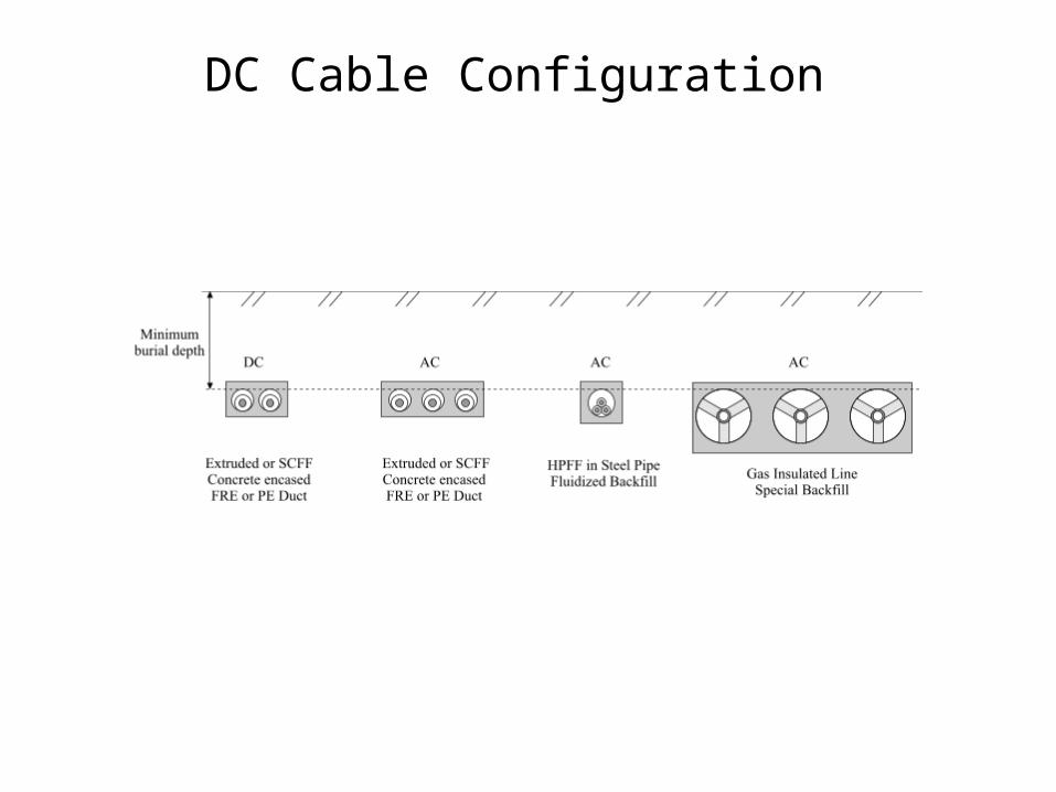
DC Cable Configuration

Bi-Pole’s Advantages: Simplest Construction, Half-Insulation Thickness
and Smaller Diameter and Longer CableConventional Bi-Pole Designs are Unsuitable
•No ground return, so lose one cable, lose circuit.
•Mutual magnetic field is perpendicular to PIT conductor
•Ground conductor is added to give N+1 security
•No outer HTSC shield: field is not contained
•Mutual magnetic field is perpendicular to PIT conductors
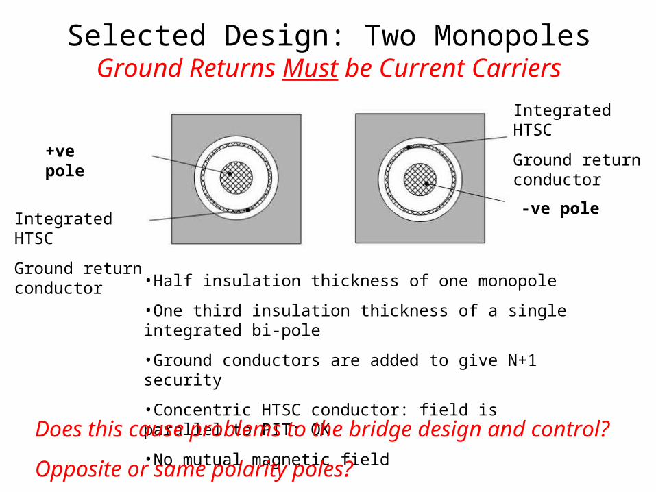
Selected Design: Two MonopolesGround Returns Must be Current Carriers
•Half insulation thickness of one monopole
•One third insulation thickness of a single integrated bi-pole
•Ground conductors are added to give N+1 security
•Concentric HTSC conductor: field is parallel to PIT: OK
•No mutual magnetic field
+ve pole
-ve poleIntegrated HTSC
Ground return conductor
Integrated HTSC
Ground return conductor
Does this cause problems to the bridge design and control?
Opposite or same polarity poles?

DC Cable Sensitivity Study: Boundary Limitations • Dry cable construction, extruded insulation, can be factory HV tested,
joints are simplest.• Voltage and current: no restriction• Fault circuit current: 2 x rated current for 1 sec and 1K rise• Maximum number of tapes in one pass on present stranding machines
is 150. Perhaps extend to 250? (Need to ask manufacturers). See video of cable factory.
• Reel:– outer diameter: 4.2m– hub diameter: 20D (D is cable OD)– Width:2.4m (could increase)– Cable net weight: 30ton (could increase).
• Installation: See video of cable factory– Tensile load: F=COF x Unit Mass x Length– Maximum safe load on cable= 50N/mm2 of stranded conductor area.
• PIT tape:– Present BSCCO minimum bend diameter: 70mm– Will tape width conform to circumference?
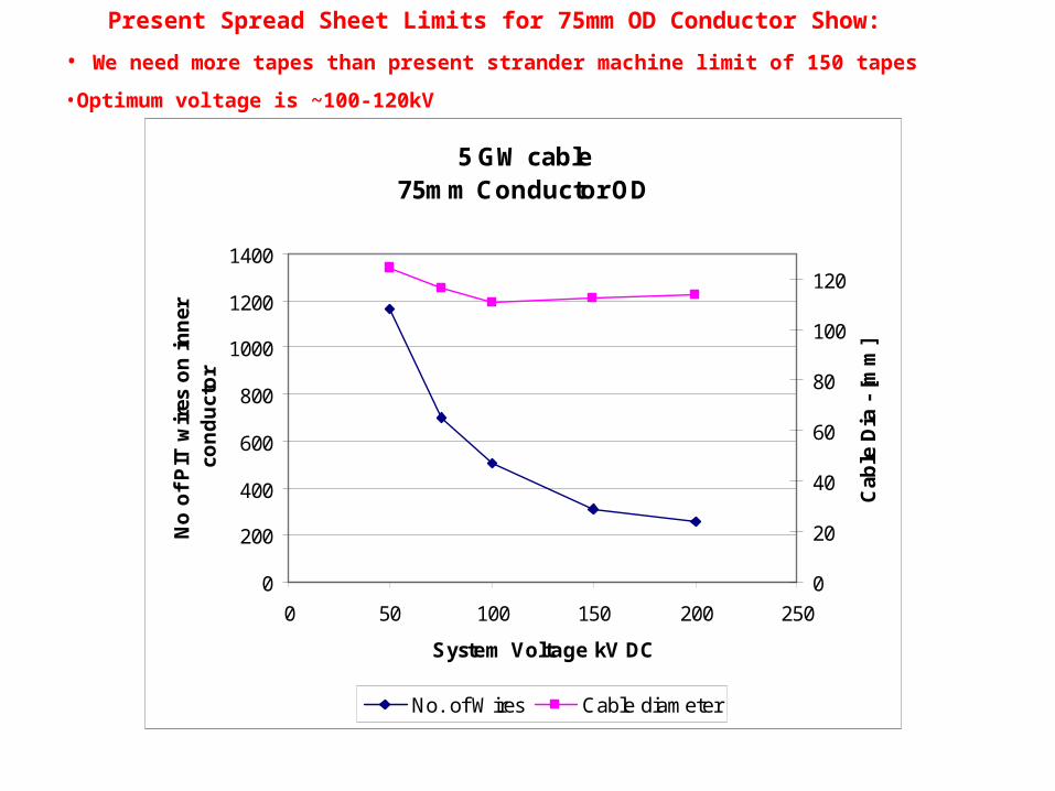
5 GW cable75mm Conductor OD
0
200
400
600
800
1000
1200
1400
0 50 100 150 200 250
System Voltage kV DC
No
of
PIT
wir
es o
n i
nn
er
con
du
cto
r
0
20
40
60
80
100
120
Cab
le D
ia -
[m
m]
No. of Wires Cable diameter
Present Spread Sheet Limits for 75mm OD Conductor Show:
• We need more tapes than present strander machine limit of 150 tapes
•Optimum voltage is ~100-120kV
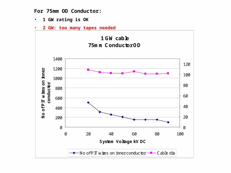
1 GW cable75mm Conductor OD
0
200
400
600
800
1000
1200
1400
0 20 40 60 80 100
System Voltage kV DC
No
of
PIT
wir
es o
n i
nn
er
con
du
cto
r
0
20
40
60
80
100
120
No of PIT wires on inner conductor Cable dia
For 75mm OD Conductor:
• 1 GW rating is OK
• 2 GW: too many tapes needed
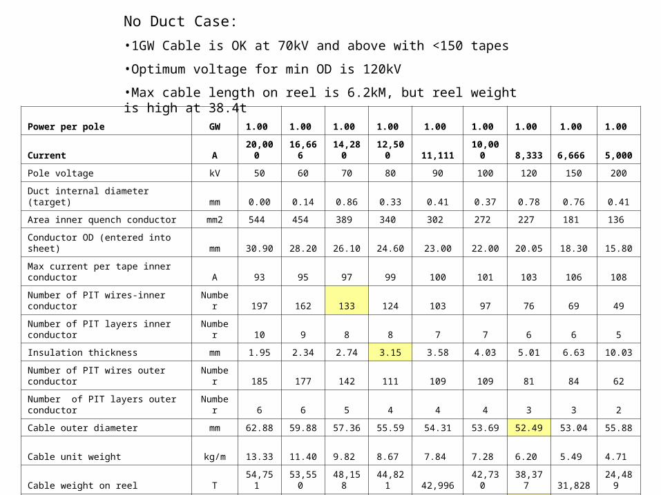
No Duct Case:
•1GW Cable is OK at 70kV and above with <150 tapes
•Optimum voltage for min OD is 120kV
•Max cable length on reel is 6.2kM, but reel weight is high at 38.4t
Power per pole GW 1.00 1.00 1.00 1.00 1.00 1.00 1.00 1.00 1.00
Current A 20,000 16,666 14,280 12,500 11,111 10,000 8,333 6,666 5,000
Pole voltage kV 50 60 70 80 90 100 120 150 200
Duct internal diameter (target) mm 0.00 0.14 0.86 0.33 0.41 0.37 0.78 0.76 0.41
Area inner quench conductor mm2 544 454 389 340 302 272 227 181 136
Conductor OD (entered into sheet) mm 30.90 28.20 26.10 24.60 23.00 22.00 20.05 18.30 15.80
Max current per tape inner conductor A 93 95 97 99 100 101 103 106 108
Number of PIT wires-inner conductor Number 197 162 133 124 103 97 76 69 49
Number of PIT layers inner conductor Number 10 9 8 8 7 7 6 6 5
Insulation thickness mm 1.95 2.34 2.74 3.15 3.58 4.03 5.01 6.63 10.03
Number of PIT wires outer conductor Number 185 177 142 111 109 109 81 84 62
Number of PIT layers outer conductor Number 6 6 5 4 4 4 3 3 2
Cable outer diameter mm 62.88 59.88 57.36 55.59 54.31 53.69 52.49 53.04 55.88
Cable unit weight kg/m 13.33 11.40 9.82 8.67 7.84 7.28 6.20 5.49 4.71
Cable weight on reel T 54,751 53,550 48,158 44,821 42,996 42,730 38,377 31,828 24,489
Cable length on reel m 4,107 4,696 4,906 5,172 5,482 5,866 6,192 5,795 5,199

Power per pole GW 1.00 1.00 1.00 1.00 1.00 1.00 1.00 1.00 1.00
Current A 20,000 16,666 14,280 12,500 11,111 10,000 8,333 6,666 5,000
Pole voltage kV 50 60 70 80 90 100 120 150 200
Duct internal diameter (target) mm 20.03 20.22 20.08 20.38 20.09 20.01 20.11 20.01 20.09
Area inner quench conductor mm2 544 454 389 340 302 272 227 181 136
Conductor OD (entered into sheet) mm 38.50 36.50 34.70 33.50 32.50 31.80 30.45 28.90 27.90
Max current per tape inner conductor A 98 101 103 105 107 108 110 112 115
Number of PIT wires-inner conductorNumb
er 202 168 137 112 108 105 81 58 56
Number of PIT layers inner conductorNumb
er 8 7 6 5 5 5 4 3 3
Insulation thickness mm 1.94 2.31 2.69 3.07 3.47 3.88 4.73 6.09 8.57
Number of PIT wires outer conductorNumb
er 180 175 137 135 101 101 102 69 75
Number of PIT layers outer conductor
Number 5 5 4 4 3 3 3 2 2
Cable outer diameter mm 69.00 66.68 64.45 63.38 62.24 61.90 61.54 61.55 64.69
Cable unit weight kg/m 14.06 12.19 10.55 9.54 8.62 8.09 7.21 6.15 5.72
Cable weight on reel kg 46,919 43,607 41,739 39,476 36,194 33,805 31,799 27,147 21,942
Cable length on reel m 3,336 3,578 3,955 4,139 4,201 4,177 4,411 4,412 3,837
20mm Duct Case:
•1GW Cable is OK at 70kV and above with <150 tapes
•Optimum voltage for min OD is 120-150kV
•Max cable length on reel is 4.4kM, but reel weight is OK at 27-32t
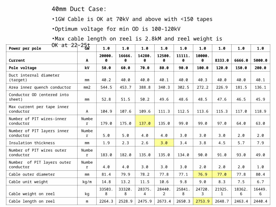
Power per pole GW 1.0 1.0 1.0 1.0 1.0 1.0 1.0 1.0 1.0
Current A 20000.0 16666.0 14280.0 12500.0 11111.0 10000.0 8333.0 6666.0 5000.0
Pole voltage kV 50.0 60.0 70.0 80.0 90.0 100.0 120.0 150.0 200.0
Duct internal diameter (target) mm 40.2 40.0 40.0 40.1 40.0 40.3 40.0 40.0 40.1
Area inner quench conductor mm2 544.5 453.7 388.8 340.3 302.5 272.2 226.9 181.5 136.1
Conductor OD (entered into sheet) mm 52.8 51.5 50.2 49.6 48.6 48.5 47.6 46.5 45.9
Max current per tape inner conductor A 104.9 107.6 109.6 111.3 112.5 113.6 115.3 117.0 118.9
Number of PIT wires-inner conductor Number 179.0 175.0 137.0 135.0 99.0 99.0 97.0 64.0 63.0
Number of PIT layers inner conductor Number 5.0 5.0 4.0 4.0 3.0 3.0 3.0 2.0 2.0
Insulation thickness mm 1.9 2.3 2.6 3.0 3.4 3.8 4.5 5.7 7.9
Number of PIT wires outer conductor Number 183.0 182.0 135.0 135.0 134.0 90.0 91.0 93.0 49.0
Number of PIT layers outer conductor Number 4.0 4.0 3.0 3.0 3.0 2.0 2.0 2.0 1.0
Cable outer diameter mm 81.4 79.9 78.2 77.8 77.1 76.9 77.0 77.8 80.4
Cable unit weight kg/m 14.8 13.2 11.5 10.6 9.8 9.0 8.3 7.5 6.7
Cable weight on reel kg 33503.8 33320.8 28375.4 28440.2 25841.8 24720.3 21925.1 18362.6 16449.6
Cable length on reel m 2264.3 2528.9 2475.9 2673.4 2650.3 2753.9 2648.7 2463.4 2440.4
40mm Duct Case:
•1GW Cable is OK at 70kV and above with <150 tapes
•Optimum voltage for min OD is 100-120kV
•Max cable length on reel is 2.8kM and reel weight is OK at 22-25t
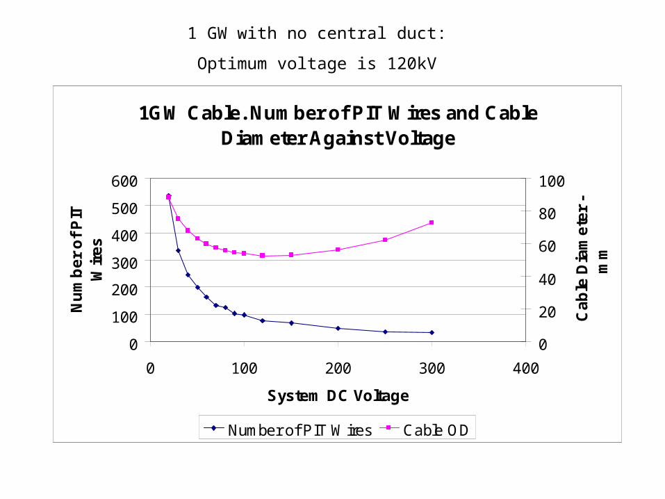
1GW Cable. Number of PIT Wires and Cable Diameter Against Voltage
0
100
200
300
400
500
600
0 100 200 300 400
System DC Voltage
Nu
mb
er
of
PIT
W
ire
s
0
20
40
60
80
100
Ca
ble
Dia
me
ter
- m
m
Number of PIT Wires Cable OD
1 GW with no central duct:
Optimum voltage is 120kV
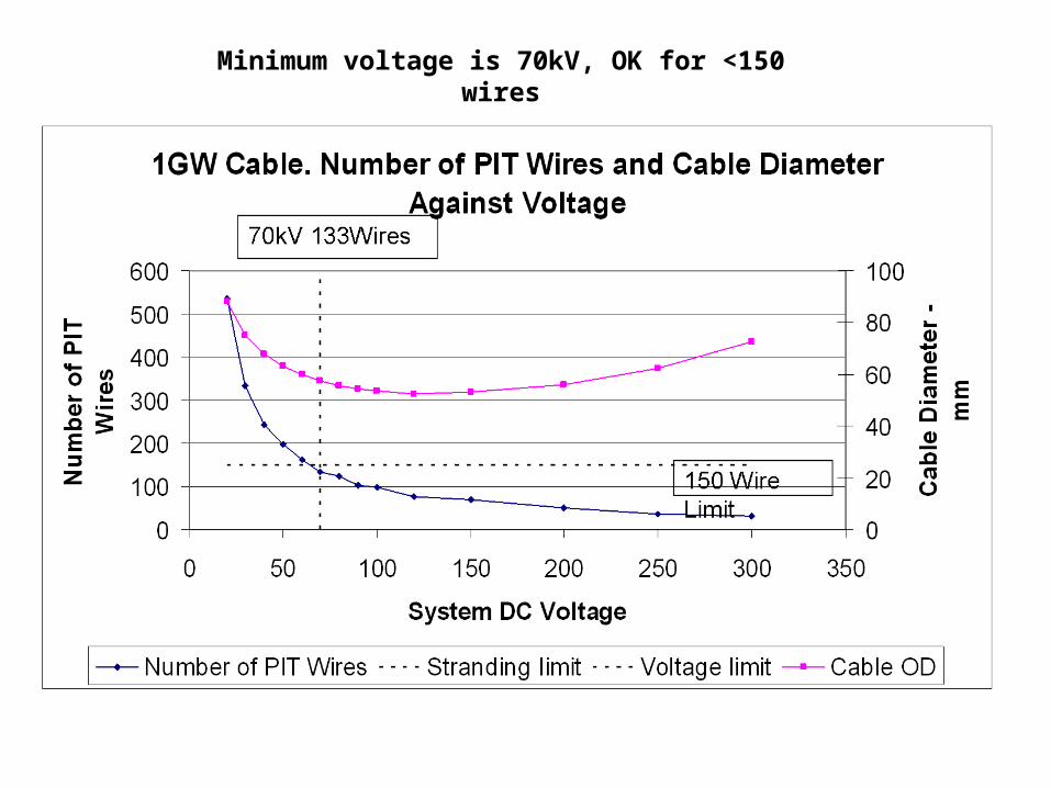
Minimum voltage is 70kV, OK for <150 wires
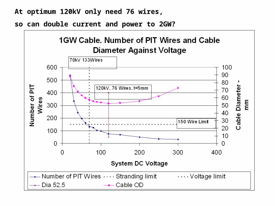
At optimum 120kV only need 76 wires,
so can double current and power to 2GW?
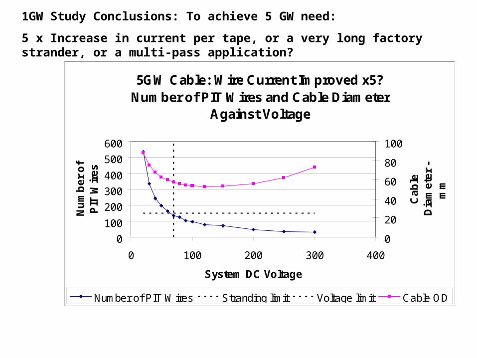
5GW Cable: Wire Current Improved x5? Number of PIT Wires and Cable Diameter
Against Voltage
0
100
200
300
400
500
600
0 100 200 300 400
System DC Voltage
Nu
mb
er
of
PIT
Wir
es
0
20
40
60
80
100
Ca
ble
D
iam
ete
r -
mm
Number of PIT Wires Stranding limit Voltage limit Cable OD
1GW Study Conclusions: To achieve 5 GW need:
5 x Increase in current per tape, or a very long factory strander, or a multi-pass application?
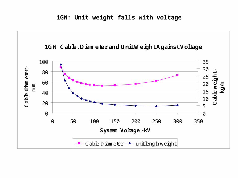
1GW Cable. Diameter and Unit Weight Against Voltage
0
20
40
60
80
100
0 50 100 150 200 250 300 350
System Voltage - kV
Ca
ble
dia
me
ter
- m
m
051015
20253035
Ca
ble
we
igh
t -
kg
/m
Cable Diameter unit length weight
1GW: Unit weight falls with voltage
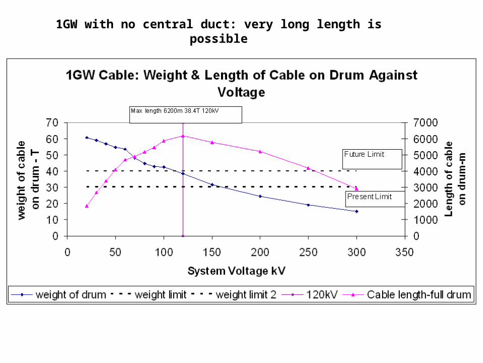
1GW with no central duct: very long length is possible
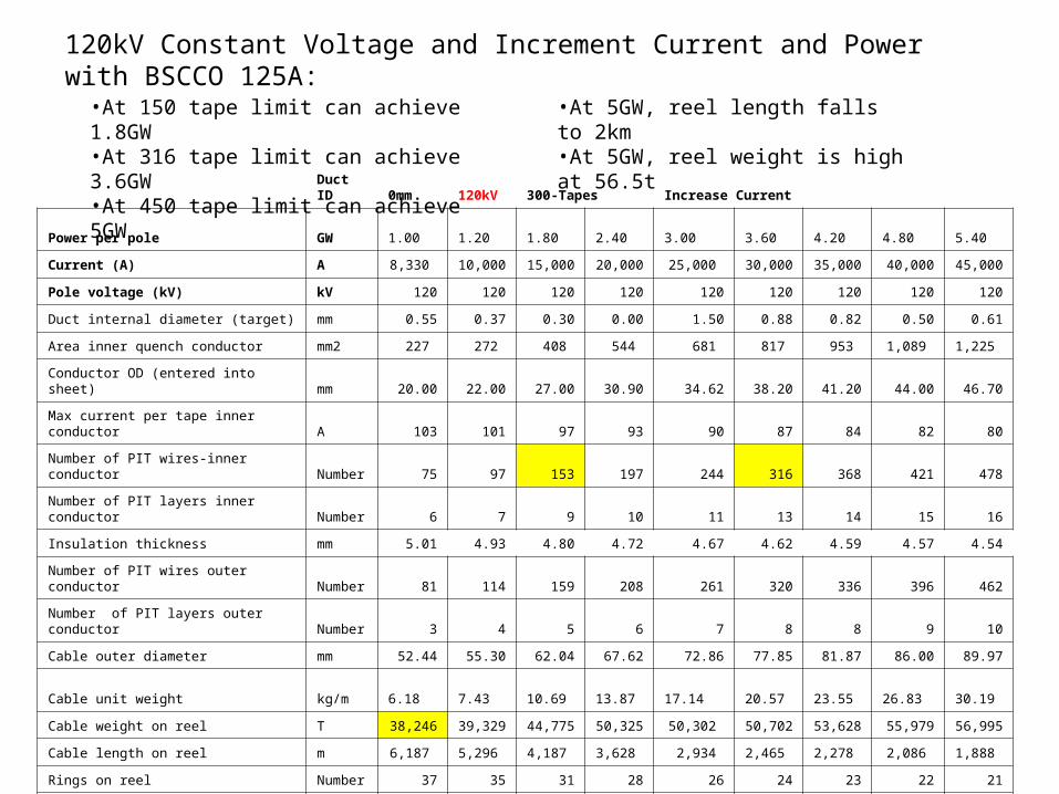
120kV Constant Voltage and Increment Current and Power with BSCCO 125A:
Duct ID 0mm 120kV 300-Tapes Increase Current
Power per pole GW 1.00 1.20 1.80 2.40 3.00 3.60 4.20 4.80 5.40
Current (A) A 8,330 10,000 15,000 20,000 25,000 30,000 35,000 40,000 45,000
Pole voltage (kV) kV 120 120 120 120 120 120 120 120 120
Duct internal diameter (target) mm 0.55 0.37 0.30 0.00 1.50 0.88 0.82 0.50 0.61
Area inner quench conductor mm2 227 272 408 544 681 817 953 1,089 1,225
Conductor OD (entered into sheet) mm 20.00 22.00 27.00 30.90 34.62 38.20 41.20 44.00 46.70
Max current per tape inner conductor A 103 101 97 93 90 87 84 82 80
Number of PIT wires-inner conductor Number 75 97 153 197 244 316 368 421 478
Number of PIT layers inner conductor Number 6 7 9 10 11 13 14 15 16
Insulation thickness mm 5.01 4.93 4.80 4.72 4.67 4.62 4.59 4.57 4.54
Number of PIT wires outer conductor Number 81 114 159 208 261 320 336 396 462
Number of PIT layers outer conductor Number 3 4 5 6 7 8 8 9 10
Cable outer diameter mm 52.44 55.30 62.04 67.62 72.86 77.85 81.87 86.00 89.97
Cable unit weight kg/m 6.18 7.43 10.69 13.87 17.14 20.57 23.55 26.83 30.19
Cable weight on reel T 38,246 39,329 44,775 50,325 50,302 50,702 53,628 55,979 56,995
Cable length on reel m 6,187 5,296 4,187 3,628 2,934 2,465 2,278 2,086 1,888
Rings on reel Number 37 35 31 28 26 24 23 22 21
Flakes on reel Number 29 26 22 20 17 15 14 13 12
Reel hub OD mm 1049 1106 1241 1352 1457 1557 1637 1720 1799
Reel external width m 2.4 2.4 2.4 2.4 2.4 2.4 2.4 2.4 2.4
Reel Flange OD m 4.2 4.2 4.2 4.2 4.2 4.2 4.2 4.2 4.2
•At 150 tape limit can achieve 1.8GW•At 316 tape limit can achieve 3.6GW•At 450 tape limit can achieve 5GW
•At 5GW, reel length falls to 2km•At 5GW, reel weight is high at 56.5t


