
ENVIRONMENTAL CONTROL UNIT (ECU)
9,000 BTUH (9K) COOLING CAPACITY
5,200 BTUH HEATING CAPACITY (GSQ386ZABNWY0**)
6,810 BTUH HEATING CAPACITY (GSQ386ZABNWY0**-R)
MODEL NUMBER GSQ386ZABNWY0** & GSQ386ZABNWY0**-R
TWO CHARACTERS “**” OF THE MODEL
NUMBER ARE USED FOR COLOR & OPTION KITS.
REMOTE, RACK MOUNT 254-00003 STANDARD & 254-00007 BULKHEAD
CAGE CODE 0WJE1
POWER (GSQ386ZABNWY0**) 115 VAC, 1 Phase, 50/60 Hz, 20 amp service
POWER (GSQ386ZABNWY0**-R) 115 VAC, 1 Phase, 50/60 Hz, 25 amp service
REFRIGERANT R-407C
REFRIGERANT CHARGE 2 LBS (32 ounces)
WEIGHT 130 LBS
OPERATION and MAINTENANCE MANUAL
WITH REPAIR PARTS LIST
568-00009-R4, 12-December-2011


Operation and Maintenance Manual
GSQ386ZABNWY0** & GSQ386ZABNWY0**-R
568-00009-R4
i
Table of Contents Chapter 1 Introduction ................................................................................................ 1-1
Section 1.01 Forward ............................................................................................... 1-1
Section 1.02 Safety Summary ................................................................................. 1-1 Section 1.03 Dangers and Warnings ........................................................................ 1-1 Section 1.04 Cautions .............................................................................................. 1-4
Chapter 2 General Information ................................................................................... 2-1 Section 2.01 Equipment Descriptions ..................................................................... 2-1
Section 2.02 Design Features .................................................................................. 2-1 a. Operational ............................................................................................... 2-1 b. Physical Characteristics ........................................................................... 2-1
Section 2.03 Special Features .................................................................................. 2-2 Section 2.04 Major Components ............................................................................. 2-3
Section 2.05 Functional Components Description .................................................. 2-4 Section 2.06 Identification ....................................................................................... 2-5
Chapter 3 Functional Description ............................................................................... 3-1 Section 3.01 Introduction ........................................................................................ 3-1
Section 3.02 Principles of Operation ....................................................................... 3-1 Section 3.03 Operational Description ...................................................................... 3-1
Chapter 4 Installation.................................................................................................. 4-1
Section 4.01 Unit Setup ........................................................................................... 4-1 Section 4.02 Power Cable (108-00061 or 108-00047) Installation ......................... 4-3
Section 4.03 Power Cable (108-00132) Installation ................................................ 4-3 Section 4.04 Remote Control Installation................................................................ 4-4 Section 4.05 Other Preparations .............................................................................. 4-7
Chapter 5 Operators Instructions ................................................................................ 5-1
Section 5.01 Operators Instructions......................................................................... 5-1 a. ECU Control Panel .................................................................................. 5-1 c. Sequence of Operations ........................................................................... 5-3
d. Shutdown Procedure ................................................................................ 5-3 e. Emergency Shutdown Procedure ............................................................. 5-3 f. Network Monitoring Feature ................................................................... 5-4
Chapter 6 Maintenance and Repair ............................................................................ 6-1 Section 6.01 Maintenance Instructions .................................................................... 6-1 Section 6.02 Service Schedule ................................................................................. 6-2
a. Preventative Maintenance Checks and Services ...................................... 6-2 b. Normal Operating Pressures .................................................................... 6-3
Section 6.03 Procedures .......................................................................................... 6-4
a. Air Filter Servicing (Not supplied with the ECU) ................................... 6-4
b. Evaporator Coil Cleaning ........................................................................ 6-4 c. Condenser Coil Cleaning ......................................................................... 6-4
Section 6.04 Field Repair ........................................................................................ 6-4 a. Leak Detection ......................................................................................... 6-5 b. Leak Repair .............................................................................................. 6-6 c. Refrigeration System Component Replacement ...................................... 6-7 d. Compressor Replacement ........................................................................ 6-8

Operation and Maintenance Manual
GSQ386ZABNWY0** & GSQ386ZABNWY0**-R
568-00009-R4
ii
e. Compressor Burnout Decontamination Procedure ................................ 6-10
f. Charging Procedures .............................................................................. 6-11 g. Charging the System by Weight ............................................................ 6-12
Chapter 7 Troubleshooting ......................................................................................... 7-1
Section 7.01 General ................................................................................................ 7-1 Section 7.02 Diagnostic Checks .............................................................................. 7-3
a. Voltage Check .......................................................................................... 7-3 b. Current Check .......................................................................................... 7-4 c. Electrical Component Diagnostics ........................................................... 7-4
d. Compressor Check ................................................................................... 7-8 Chapter 8 Specifications ............................................................................................. 8-1 Chapter 9 Reference Drawings ................................................................................... 9-1
Section 9.01 ECU Electrical Schematic (502-00033) ............................................. 9-1
Section 9.02 Remote Control Schematic (502-00037) ............................................ 9-3 Section 9.03 ECU Wiring Diagram (514-00022) .................................................... 9-4
Section 9.04 54-00003, Remote Wiring Diagram (514-00024) .............................. 9-5 Section 9.05 254-00007, Remote Wiring Diagram (514-00029) ............................ 9-6
Section 9.06 Refrigeration Schematic (520-00072) ................................................ 9-7 Chapter 10 Parts List and Assembly Drawings .......................................................... 10-1
EXPORT CONTROL
THIS DOCUMENT IS SUBJECT TO THE INTERNATIONAL TRAFFIC IN ARMS
REGULATIONS (ITAR), 22 CFR 120-130, AND/OR THE EXPORT
ADMINISTRATION REGULATIONS (EAR), 15 CFR 730-774, OF THE UNITED
STATES OF AMERICA. ANY TECHNICAL DATA CONTAINED IN THIS
DOCUMENT MAY NOT BE EXPORTED, RELEASED OR OTHERWISE
DISCLOSED TO ANY FOREIGN ENTITY OR FOREIGN NATIONAL INSIDE OR
OUTSIDE OF UNITED STATES WITHOUT FIRST OBTAINING ANY REQUIRED
EXPORT LICENSE OR OTHER U.S. GOVERNMENT APPROVAL.

Operation and Maintenance Manual
GSQ386ZABNWY0** & GSQ386ZABNWY0**-R
568-00009-R4
1-1
Chapter 1 Introduction
Section 1.01 Forward
This Operations and Maintenance Manual applies to an Environmental Control Unit
(ECU) designed for field deployment. This ECU is designed to provide years of trouble-
free service if installed, operated, and maintained in accordance with this manual. This
manual provides user instruction for the safe operation of the ECU. This manual also
provides maintenance, trouble shooting, and repair information to be used by trained
technicians. Damage to the unit from improper installation, operation, or maintenance is
not covered by the warranty.
Section 1.02 Safety Summary
a. This ECU has been designed for safe and intuitive operation and maintenance.
However, operators and service personnel must thoroughly read and understand
the information presented in this manual. Improper use or servicing of this ECU
can endanger personnel and damage the ECU.
b. Throughout this manual, statements of danger, warning and caution are noted.
Danger and Warning statements are prefaced by the term:
DANGER! and WARNING! Danger and Warning statements denote guidance that must be adhered to in
order to avoid DEATH or SERIOUS INJURY.
c. Statements of caution are prefaced by the term:
ATTENTION! Caution statements denote guidance that must be adhered to in order to avoid
damaging the equipment, improper operation, and possible voiding of the
warranty.
Section 1.03 Dangers and Warnings
The following dangers and warnings apply to all operating and service tasks that may be
performed on this ECU. All personnel who use or service this equipment must fully
understand and act in accordance with these warnings. They are listed in the sequential
order they appear in this manual.
DANGER!
This ECU operates on high voltage. DEATH or SERIOUS INJURY
can result if proper safety procedures are not observed. Always
disconnect the ECU from its power source prior to servicing.
Operation and Maintenance Manual
GSQ386ZABNWY0** & GSQ386ZABNWY0**-R
568-00009-R4
1-2
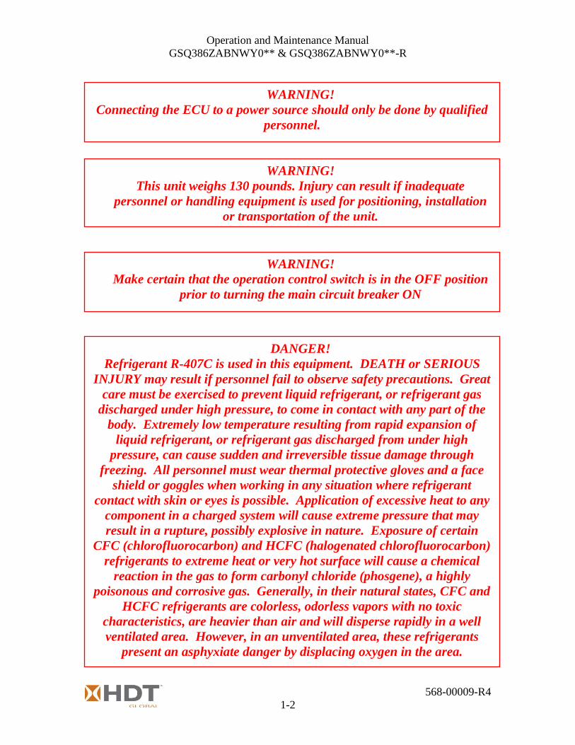
WARNING!
Make certain that the operation control switch is in the OFF position
prior to turning the main circuit breaker ON
WARNING!
Connecting the ECU to a power source should only be done by qualified
personnel.
WARNING!
This unit weighs 130 pounds. Injury can result if inadequate
personnel or handling equipment is used for positioning, installation
or transportation of the unit.
DANGER!
Refrigerant R-407C is used in this equipment. DEATH or SERIOUS
INJURY may result if personnel fail to observe safety precautions. Great
care must be exercised to prevent liquid refrigerant, or refrigerant gas
discharged under high pressure, to come in contact with any part of the
body. Extremely low temperature resulting from rapid expansion of
liquid refrigerant, or refrigerant gas discharged from under high
pressure, can cause sudden and irreversible tissue damage through
freezing. All personnel must wear thermal protective gloves and a face
shield or goggles when working in any situation where refrigerant
contact with skin or eyes is possible. Application of excessive heat to any
component in a charged system will cause extreme pressure that may
result in a rupture, possibly explosive in nature. Exposure of certain
CFC (chlorofluorocarbon) and HCFC (halogenated chlorofluorocarbon)
refrigerants to extreme heat or very hot surface will cause a chemical
reaction in the gas to form carbonyl chloride (phosgene), a highly
poisonous and corrosive gas. Generally, in their natural states, CFC and
HCFC refrigerants are colorless, odorless vapors with no toxic
characteristics, are heavier than air and will disperse rapidly in a well
ventilated area. However, in an unventilated area, these refrigerants
present an asphyxiate danger by displacing oxygen in the area.

Operation and Maintenance Manual
GSQ386ZABNWY0** & GSQ386ZABNWY0**-R
568-00009-R4
1-3
WARNING!
Disconnect the ECU from the power source and remove the power
connector from the ECU prior to performing any service or
maintenance tasks.
WARNING!
Use rubber gloves and safety glasses and ventilate the workspace. The
oil from a burnout could cause serious skin irritation and possibly
burns. In some cases, the fumes are toxic. Use extreme caution when
sampling oil.
WARNING!
Fans and blowers are rotating parts that can cause severe injury.
They may start without warning.
Always disconnect the ECU from its power source prior to servicing.
Do not operate the ECU with panels removed.
WARNING!
Heating elements reach high temperatures. Severe burns are possible.
Allow elements to cool before servicing.
DANGER!
DEATH or SERIOUS INJURY may result if personnel fail to observe
the following safety precautions
DANGER!
Troubleshooting must only be performed by qualified technicians.
DEATH or SERIOUS INJURY can occur.
DANGER!
Many diagnostic tests require power to be present. Extreme care must
be exercised to avoid DEATH or SERIOUS INJURY. High voltage is
present in the electrical panel.

Operation and Maintenance Manual
GSQ386ZABNWY0** & GSQ386ZABNWY0**-R
568-00009-R4
1-4
Section 1.04 Cautions
The following cautions apply to all operating and service tasks that may be performed on
this ECU. All personnel who use or service this equipment must fully understand and act
in accordance with these cautions. Caution statements denote guidance that must be
adhered to in order to avoid damaging the equipment, improper operation, and possible
voiding of the warranty. They are listed in the sequential order they appear in this
manual.
ATTENTION!
Unit must be operated with the correct voltage and frequency.
Failure to do so may result in damage and operational failure of the
unit.
ATTENTION!
All repairs must be carried out in compliance with EPA Section No. 608
and applicable local air quality regulations.
ATTENTION!
Do not attempt to make any adjustments or repairs without proper
tools.
ATTENTION!
When using compressed air to clean filters or coils, limit pressure to
35 PSI.
ATTENTION!
When replacing a burned-out compressor, it is mandatory that the
refrigeration system be thoroughly cleaned before operating the
replacement compressor.

Operation and Maintenance Manual
GSQ386ZABNWY0** & GSQ386ZABNWY0**-R
568-00009-R4
1-5
ATTENTION!
A refrigeration system should be evacuated whenever the system has
been open in such a manner that there is a possibility that air and
moisture could have entered the system. The evacuation process is
intended to remove non-condensable gases and moisture from the
portion of the system to be evacuated. The most important contaminant
to be removed is moisture. To remove moisture from the system, it must
first be boiled into vapor. Before water will boil at ordinary room
temperature, for example, at 70°F the vacuum must be 29¼ inches of
mercury at 30 inches of mercury barometric pressure. This means that
the system must be within ¾ inches of mercury of absolute zero
pressure. This low vacuum should be measured by using an absolute
pressure gauge, such as an electronic gauge. For this reason, a good
vacuum pump must be used to accomplish good dehydration.

Operation and Maintenance Manual
GSQ386ZABNWY0** & GSQ386ZABNWY0**-R
568-00009-R4
1-6
This page intentionally left blank.

Operation and Maintenance Manual
GSQ386ZABNWY0** & GSQ386ZABNWY0**-R
568-00009-R4
2-1
Chapter 2 General Information
Section 2.01 Equipment Descriptions
a. The ECU is a packaged system designed to operate in a portable field use
application, providing conditioned air to a shelter.
b. The ECU is controlled with a remote rack mounted control unit.
c. The ECU operates using 115VAC, 1-phase, 50/60Hz power supplied by a
generator or shore power via an auxiliary power plug located on the ECU. 20
amp service for models GSQ386ZABNWY0** & 25 amp service for models
GSQ386ZABNWY0**-R.
d. The refrigeration system uses R-407C refrigerant and has a cooling
capacity at 60 Hz of 9,000 BTU/Hr at 95° F ambient outside temperatures
(95°F Ambient Dry Bulb (ADB) / 80°F Entering Dry Bulb (EDB) / 70°F
Entering Wet Bulb (EWB)).
e. The heating system is furnished with a nominal heat of 5,200 BTU/Hr
(GSQ386ZABNWY0**) or 6,810 BTU/Hr (GSQ386ZABNWY0**-R)
which consists of resistive type heater in addition to the fan heat.
Section 2.02 Design Features
a. Operational
Table 2.1
b. Physical Characteristics
Table 2.2
Capacity…………………………………………….….. 9,000 BTU/Hr
Air Flow…………………………………………….….. 370 CFM
Heating Capacity (GSQ386ZABNWY0**) …………… 5,200 BTU/Hr, Nominal
Heating Capacity (GSQ386ZABNWY0**-R) ………… 6,810 BTU/Hr, Nominal
Design Maximum Ambient Temperature……………… 1350 F
Minimum Ambient Cooling……………………….…… to 450 F
Minimum Ambient Heating……………………….…… to –250 F
Height………………………………….…….….. 16.00”
Width………………………………….……….… 28.00”
Depth…………………………………….…….… 26.00” (27.68” over duct flange)
Weight…………………………….……….…….. 130 Pounds
Operation and Maintenance Manual
GSQ386ZABNWY0** & GSQ386ZABNWY0**-R
568-00009-R4
2-2
Section 2.03 Special Features
a. SALT SPRAY PROTECTION
1. The cabinet is constructed of aluminum 5052-H32 alloy sheet; and painted
in accordance with the specification.
2. All external hardware and all internal hardware is stainless steel,
aluminum or have been protected against corrosion per the specification.
3. The evaporator coil is constructed from copper tubes and aluminum fins.
The condenser coil is an aluminum micro-channel design.
4. The evaporator coil is coated with a protective coating.
The condenser coil is treated with corrosion resistant clad materials.
b. MAINTENANCE FEATURES
1. Sight Glass - A sight glass with a moisture indicator is provided to detect
any moisture in the refrigeration circuit and low refrigerant levels. This
feature is located on the side of the ECU
2. Service Valves - Suction and discharge Schrader service valves have been
provided to enable servicing of the ECU. These features are located on
the side of the ECU.
c. SAFETY FEATURES
1. Low/High Pressure Switches - Low and high-pressure switches are
provided. They are factory set for the application. The low pressure
switch will disengage control power to the compressor contactor if suction
pressure drops below a specific pressure. The high pressure switch will
shut off the compressor if the discharge pressure rises above a specific
pressure. These pressure switches are installed as safety devices and will
help prevent compressor failure or other serious damage to the system
components. If the ECU begins to cycle on high or low pressure, the unit
should be removed from service and have the appropriate maintenance
performed.
2. Pressure Relief Valve - The ECU is fitted with a relief valve that will
discharge refrigerant should internal pressure exceed design parameters.
3. Overtemp Safety Switch - The ECU heater section is equipped with dual
overtemp safety switches. If the temperature in the heater cabinet exceeds
the set point of the switch (1400 F), power to the heater elements will be
interrupted.

Operation and Maintenance Manual
GSQ386ZABNWY0** & GSQ386ZABNWY0**-R
568-00009-R4
2-3
Section 2.04 Major Components
a. Electrical Compartment 1. All of the major electrical control components and the input power connection
are mounted in a control compartment on the rear of the ECU.
2. System controls are located on the remote control, which connects to the front
of the ECU.
3. The controls and electrical components are access by removing the rear, side
and/or top covers.
b. Evaporator Compartment 1. Contains the evaporator coil, expansion valve, blower, and some refrigeration
components.
2. Access to the compartment is gained by removing the side or top covers.
c. Condenser compartment 1. Contains the condenser blower, compressor and service features.
2. Access to the compartment is gained by removing the side or top covers.
d. Filter (not supplied)
1. The ECU should have a air filter installed on the ductwork of the return air
entering the system.
Figure 2.1

Operation and Maintenance Manual
GSQ386ZABNWY0** & GSQ386ZABNWY0**-R
568-00009-R4
2-4
Section 2.05 Functional Components Description
Table 2.3
COMPONENT
FILTER DRIER
SIGHT GLASS
HIGH PRESSURE SWITCH
LOW PRESSURE SWITCH
HEATER SAFETY SYSTEM
DISCHARGE PRESSURE SERVICE VALVE
SUCTION PRESSURE SERVICE VALVE
RACK MOUNT REMOTE CONTROL
THERMOSTAT CONTROL BOARD (TST)
THERMOSTATIC EXPANSION VALVE (TXV)
COMPRESSOR
EVAPORATOR COIL
CONDENSER COIL
FAN MOTOR (EVAPORATOR )
FAN MOTOR (CONDENSER)
FUNCTION
Filters impurities and absorbs moisture from liquid
refrigerant.
Provides means to monitor system charge and operation.
High Pressure set to break on excess pressure 500 psig.
(Auto Reset).
Shuts down the AC when refrigeration system pressures
falls below 35 psig (Auto Reset).
High Limit Trip Switch set to break on electric heater
compartment temperature rising above 140F.
For adding refrigerant charge and to diagnose system
pressures.
For adding refrigerant charge and to diagnose system
pressures.
System Fan-On, Off, Auto-On.
Remote control has functions for temperature control
settings, switching and network monitoring.
Thermostat (Heat / Cool / Auto Select).
- Prevents compressor from short cycling.
- Allows the ECU to start and pressurize in low
ambient conditions.
TXV set to maintain superheat of 8 – 15°F.
Rotary type.
The evaporator coil is constructed from copper tubes and
aluminum fins and is E-coated with a protective coating.
The condenser coil is an aluminum micro-channel design
and is treated with corrosion resistant clad materials.
A single motor that drives the evaporator blower wheel.
A single motor that drives the condenser blower wheel.

Operation and Maintenance Manual
GSQ386ZABNWY0** & GSQ386ZABNWY0**-R
568-00009-R4
2-5
Section 2.06 Identification
Figure 2.2
Parts List, ECU, Remote & sensor cable, Ref. Figure 2.2
Item HDT Part # DESCRIPTION QTY
1 GSQ386ZABNWY0** ENVIRONMENTAL CONTROL UNIT (ECU) 1
1 GSQ386ZABNWY0**-R ENVIRONMENTAL CONTROL UNIT (ECU) 1
2 254-00003/254-00007 REMOTE CONTROL 1
3 019-00090 CABLE, CAT 5E CABLE 1
NOMENCLATURE HDT Model Number **
ENVIRONMENTAL CONTROL
UNIT, 9K BTU, 5.2K BTU HEAT GSQ386ZABNWY0** Two characters “**”
of the model number
are used for color and
option kits. ENVIRONMENTAL CONTROL
UNIT, 9K BTU, 6.8K BTU HEAT GSQ386ZABNWY0**-R

Operation and Maintenance Manual
GSQ386ZABNWY0** & GSQ386ZABNWY0**-R
568-00009-R4
2-6
Figure 2.3 (sample data only)

Operation and Maintenance Manual
GSQ386ZABNWY0** & GSQ386ZABNWY0**-R
568-00009-R4
3-1
Chapter 3 Functional Description
Section 3.01 Introduction
This chapter describes the operation of the refrigeration and heating sub-systems.
Section 3.02 Principles of Operation
a. The refrigeration system is a closed-loop circuit in which refrigerant is
continuously circulated by the pressure differential created by the compressor.
b. The compressor maintains high side condensing pressure, and the thermostatic
expansion valve separates the high-pressure side from the low-pressure side at the
evaporator coil inlet.
c. The compressor is designed to increase refrigerant pressure to a level high enough
for it to be cooled and condensed into liquid by the ambient air being drawn over
the condenser coil.
d. The liquid refrigerant flows through the filter/drier, where moisture and other
impurities are removed, then through the sight glass, a device for visual inspection
of the refrigerant.
e. The liquid then flows through the thermostatic expansion valve, which meters the
high-pressure liquid into the low-pressure refrigerant circuit. The thermostatic
expansion valve is a pressure-reducing device metering high-pressure liquid
refrigerant into the low-pressure evaporator coil in the amount required for the
operating conditions.
f. As the liquid enters the low pressure side of the circuit, it flows through the
evaporator coil, boils by absorbing the latent heat of vaporization at the low
pressure, and evaporates into a low pressure, low temperature gas. Heat from the
surrounding air is extracted through the finned tubing of the evaporator coil by the
refrigerant.
g. The gas then returns to the compressor, where it is compressed and forced into the
condenser coil, completing the cycle. The relationship of components involved in
this process are illustrated in section 9.06 Refrigeration Schematic, on page 9-7.
Section 3.03 Operational Description
a. In Cool mode (Auto On with sensor calling for cooling):
1. Compressor, condenser fan and evaporator blower start.
2. The Compressor takes low pressure, low temperature gas and compresses it to
a high temperature, high-pressure gas.
Operation and Maintenance Manual
GSQ386ZABNWY0** & GSQ386ZABNWY0**-R
568-00009-R4
3-2
3. The refrigerant flows from the compressor to the condenser coil. The
condenser fan forces outside ambient air out through the condenser coil. Heat
is removed from the high temperature, high-pressure gas from the compressor
by the flow of air over the condenser coil and is changed into a low
temperature, high-pressure liquid.
4. The refrigerant filter/drier removes any moisture (water vapor) or impurities
that may be carried by the liquid refrigerant.
5. The refrigerant then flows through the liquid sight glass. This device indicates
the presence of moisture and state of refrigerant in the system.
6. The expansion valve senses the temperature and pressure of the refrigerant as
it leaves the evaporator coil. By use of a sensing bulb and an internal equalizer
the valve constantly adjusts the flow of liquid refrigerant to the evaporator
coil.
7. As the liquid refrigerant leaves the expansion valve it enters the evaporator
coil. Warm air being drawn across the fins and tubes of the coil causes the
refrigerant to boil and change to a gas (vapor). The evaporator fan draws the
warm air from the conditioned space through the evaporator coil. As the air
from the conditioned space comes in contact with the evaporator coil, the air
is cooled.
8. The refrigerant gas is then drawn back to the compressor and the cycle is
repeated.
b. In Heat mode (Auto On with sensor calling for heating):
1. The evaporator blower starts and the heating elements are energized.
2. The evaporator blower circulates return air over the heating elements. Air
warmed by the elements exits out the supply grille.
3. Power to the elements will be interrupted if the over-temperature switch
senses temperatures greater than 140°F.
c. In Fan mode:
1. The evaporator blower starts.
2. Air is circulated from the return grille, exiting the supply grille.

Operation and Maintenance Manual
GSQ386ZABNWY0** & GSQ386ZABNWY0**-R
568-00009-R4
4-1
Chapter 4 Installation
Section 4.01 Unit Setup
a. The unit is to be installed up against a shelter wall with the supply and return duct
flanges protruding into the conditioned space. These flanges can be connected to
supply and return plenums as necessary. If the unit is installed through the side
wall of a shelter the minimum opening size should be 16.25” high by 28.25”
wide. The ECU should be supported from underneath on the outer side of the
shelter. Four 3/8-16 threaded mounting holes are provided for securing the ECU.
See figures 4.1 and 4.2.
b. The ECU should be set in a level location for best operation, and should not be on
an incline of greater than 10° in any direction.
ATTENTION!
Unit must be operated with the correct voltage and frequency. Failure
to do so may result in damage and operational failure of the unit.
WARNING!
Connecting the ECU to a power source should only be done by qualified
personnel.
WARNING!
This unit weighs 130 pounds. Injury can result if inadequate
personnel or handling equipment is used for positioning, installation
or transportation of the unit.
DANGER!
This ECU operates on high voltage. DEATH or SERIOUS INJURY
can result if proper safety procedures are not observed. Always
disconnect the ECU from its power source prior to servicing.

Operation and Maintenance Manual
GSQ386ZABNWY0** & GSQ386ZABNWY0**-R
568-00009-R4
4-2
Figure 4.1
Figure 4.2

Operation and Maintenance Manual
GSQ386ZABNWY0** & GSQ386ZABNWY0**-R
568-00009-R4
4-3
Section 4.02 Power Cable (108-00061 or 108-00047) Installation
a. These power cables are used on models GSQ386ZABNWY0**.
b. Put the main circuit breaker, found on the control panel, in the OFF position.
c. Attach the power cable connector to the power connector located on the back of
the ECU, labeled J1. Ensure the connector is tightened securely. Only three of
the five pins on this connector are utilized with Pin A = Black (L1), Pin D =
Green (Ground) & Pin E = White (Neutral). See figure 4.3A.
d. Connect the opposite end to a 20 amp 115V, 50 or 60 Hz power source. Only
three of the four pins of cable 108-00061's connector are utilized with Pin A =
Black (L1), Pin B = White (Neutral) & Pin D = Green (Ground). See figure 4.3A.
e. A grounding wire can be connected to the ground stud GND located underneath
the J1 connection on the rear of the ECU.
Figure 4.3A External Power Cable (108-00061 or 108-00047)
Section 4.03 Power Cable (108-00132) Installation
a. This power cable is used on models GSQ386ZABNWY0**-R.
b. Put the main circuit breaker, found on the control panel, in the OFF position.
c. Attach the power cable connector to the power connector located on the back of
the ECU, labeled J1. Ensure the connector is tightened securely. This model only
has three pins on the ECU connector with Pin A = Black (L1), Pin B = White
(Neutral) & Pin C = Green (Ground) . See figure 4.3B.

Operation and Maintenance Manual
GSQ386ZABNWY0** & GSQ386ZABNWY0**-R
568-00009-R4
4-4
d. Connect the opposite end to a 25 amp 115V, 50 or 60 Hz power source. Only
three of the four pins of cable 108-00132's connector are utilized with Pin A =
Black (L1), Pin B = White (Neutral) & Pin D = Green (Ground). See figure 4.3B.
e. A grounding wire can be connected to the ground stud GND located underneath
the J1 connection on the rear of the ECU.
Figure 4.3B External Power Cable (108-00132)
Section 4.04 Remote Control Installation
a. Standard remote control 254-00003. See figures 4.4 thru 4.6.
1. The remote control should be mounted in the control rack of the installation.
2. The external cable of the remote control should be routed and connected to the
front face of the ECU into connection J2. See figure 4.4.
3. There is a ground stud connection available on the rear of the remote.
4. The sensor CAT-5 cable (019-00090) should be connected to the back of the
remote sensor input. This cable should be routed and connected to the front
face of the ECU into connection RS1. See figure 4.6

Operation and Maintenance Manual
GSQ386ZABNWY0** & GSQ386ZABNWY0**-R
568-00009-R4
4-5
Figure 4.4
Figure 4.5 Standard Remote Control (254-00003)

Operation and Maintenance Manual
GSQ386ZABNWY0** & GSQ386ZABNWY0**-R
568-00009-R4
4-6
Figure 4.6 Remote Sensor Cable Connection
b. Bulkhead remote control 254-00007. See figures 4.6 and 4.7.
1. The remote control should be mounted in the control rack of the installation.
2. The external cable of the remote control, Item 1 in figure 4.7 (108-00084),
should be routed and connected to the bulkhead connector Item 2 in figure 4.7
(not supplied) at the junction plate/box.
3. The remote cable extension, Item 3 in figure 4.7 (108-00085), should be
routed and connected to the front face of the ECU into connection J2.
4. There is a ground stud connection available on the rear of the remote.
5. The sensor CAT-5 cable (019-00090) should be connected to the back of the
remote sensor input. This cable should be routed and connected to the front
face of the ECU into connection RS1. If there is a RJ45 thru connector at the
junction plate/box, an additional CAT-5 cable is needed to connect to RS1.
Figure 4.7 Bulkhead Remote Control (254-00007)

Operation and Maintenance Manual
GSQ386ZABNWY0** & GSQ386ZABNWY0**-R
568-00009-R4
4-7
Section 4.05 Other Preparations
a. Ensure that the condensate drain, found on the side of the ECU is unobstructed.
A hose with a ½” NPT fitting may be attached to the drain coupling to route the
water to a desired discharge location.
Figure 4.8 Condensate Drain location

Operation and Maintenance Manual
GSQ386ZABNWY0** & GSQ386ZABNWY0**-R
568-00009-R4
4-8
This page intentionally left blank.

Operation and Maintenance Manual
GSQ386ZABNWY0** & GSQ386ZABNWY0**-R
568-00009-R4
5-1
Chapter 5 Operators Instructions
Section 5.01 Operators Instructions
This chapter will provide operational instruction for the Environmental Control Unit
(ECU) and Remote Controller. Review and understand these instructions before
operating the unit.
a. ECU Control Panel
Refer to Figure 5.1 for the arrangement and identification of the controls. The
control panel contains the following switches and indicators:
Figure 5.1
1. Main Circuit Breaker
a) The main circuit breaker should be in the OFF position during the unit
setup to avoid the risk of damage to the unit.
WARNING!
Make certain that the Mode switch on the Remote Controller is in
the OFF position prior to turning the main circuit breaker ON

Operation and Maintenance Manual
GSQ386ZABNWY0** & GSQ386ZABNWY0**-R
568-00009-R4
5-2
b) The circuit breaker must then be set to the ON position to operate the
ECU.
b. Remote Control Panel
Refer to figure 5.2 for the arrangement and identification of the controls. The
control panel contains the following switches and indicators:
Figure 5.2
1. Mode Toggle Switch
a) In “AUTO” mode, the heating and cooling will operate automatically. The
heat will come on when the temperature drops below 63 degrees and will
turn off when the temperature rises above 65 degrees. The compressor
will come on when the temperature rises above 77 degrees and will turn

Operation and Maintenance Manual
GSQ386ZABNWY0** & GSQ386ZABNWY0**-R
568-00009-R4
5-3
off when the temperature drops below 75 degrees. The compressor will
remain energized for a minimum of one minute regardless of the
temperature. Once the temperature has dropped below 75 degrees the
compressor will de-energized for a minimum of 3 minutes regardless of
the temperature.
b) In “Fan” mode, the fans will run continually for air circulation.
c) In “OFF” mode, no heating or cooling will take place.
c. Sequence of Operations
1. Verify that the Mode Toggle Switch on the remote controller is in the OFF
position.
2. Verify that 115 VAC, 1 Phase, 50/60 HZ power to has been properly
connected to the ECU. 20 amp service for models GSQ386ZABNWY0** &
25 amp service for models GSQ386ZABNWY0**-R.
3. Verify that the remote controller is connected to the ECU.
4. Verify that the remote controller is connected to the temperature sensor on the
ECU.
5. Turn the Main Circuit Breaker to “ON”.
6. Select mode option for ECU.
a) The “AUTO” mode selects heating and cooling as required.
b) The “FAN” mode circulates air without heating or cooling.
c) In “OFF” mode, no heating or cooling will take place.
d. Shutdown Procedure
1. Turn the Mode Toggle Switch to OFF.
2. Verify the unit’s fan stops.
e. Emergency Shutdown Procedure
1. Turn Main Circuit Breaker to OFF.
2. Interrupt incoming power by disconnecting the power cord from the power
source.
3. Disconnect the power cable from the ECU.

Operation and Maintenance Manual
GSQ386ZABNWY0** & GSQ386ZABNWY0**-R
568-00009-R4
5-4
f. Network Monitoring Feature
1. The remote controller has a network monitoring feature for offsite monitoring
of the ECU's operation. This utilizes Simple Network Management Protocol
(SNMP) v1 logic.
a) Default IP Address: 192.168.0.1
b) Default Password: password
c) Read Community String: public
d) Write Community String: private
2. Variables Used:
a) CONTACT 1 closed - Cool mode enabled
b) CONTACT 2 closed - Evaporator Fan is powered
c) CONTACT 3 closed - Heat mode enabled
d) EXT TEMP - return air temperature (°C default)
3. There is an Ethernet connection to the left of the mode switch on the front of
the remote controller. This port is utilized in connecting the remote to the
installation's network in order to utilize this functionality. When connected
and powered up, the Ethernet LINK amber LED will light, the TX green LED
will light during activity. See figure 5.3.
4. Please contract HDT if a copy of the Management Information Base (MIB) is
needed or for further information on this feature.
Figure 5.3

Operation and Maintenance Manual
GSQ386ZABNWY0** & GSQ386ZABNWY0**-R
568-00009-R4
6-1
Chapter 6 Maintenance and Repair
Section 6.01 Maintenance Instructions
a. Preventive Maintenance Checks and Services are essential to ensure that the unit
is ready for operation at all times. They correct defects and deficiencies before
they can cause serious damage or complete failure of the equipment. Any
effective preventive maintenance program must begin with instruction to all
operators to report all unusual conditions noted during daily checks or actual
operation to the appropriate maintenance personnel.
b. A system should be established to record all problems, defects, and deficiencies
noted by operators and discovered during maintenance inspections together with
the corrective actions taken.
c. A schedule for preventive maintenance inspection and service should be
established immediately after installation of the unit. A quarterly interval is
recommended for normal operating conditions. Any component requiring
preventive maintenance at an interval more than quarterly is specifically identified
in Preventive Maintenance Checks and Services Table, Table 6.1. When
operating under unusual conditions, such as an extremely dusty, dirty, or sandy
environment, it may be necessary to reduce the interval to monthly or less
depending on the severity of the environmental conditions.
d. Stand-by, non-operating units should be rotated on a last in, last out basis. Any
unit not operating for one (1) year should be tested. A walk-by, visual inspection
should be done monthly. Look for physical damage due to material handling and
evidence of oil leakage around the unit. Any unit that shows evidence of physical
damage or oil leakage must be tested.
e. The refrigerant compressor and its drive motor are hermetically sealed. The
compressor crankcase has a lifetime supply of oil and is pressure lubricated by an
internal oil pump. If compressor failure or motor burnout occurs, the compressor
must be replaced. Refer to the Recommended Spare Parts list for the correct
replacement part. The blower motor has double shielded bearings that are
permanently lubricated. These bearings are lubricated with a high-grade ball and
roller grease of medium consistency and polyurethane base. If a situation occurs
where the bearings need lubrication, the bearings must be removed and replaced
or repacked with the above referenced lubricant or approved equivalent.
f. The Preventive Maintenance Checks and Services Table lists the preventive
maintenance checks and services that should be performed at quarterly (or
otherwise established) intervals. The Preventive Maintenance Checks and
Services items in the table have been arranged in a logical sequence to provide for
greater personnel efficiency and least amount of required maintenance downtime.

Operation and Maintenance Manual
GSQ386ZABNWY0** & GSQ386ZABNWY0**-R
568-00009-R4
6-2
Section 6.02 Service Schedule
a. Preventative Maintenance Checks and Services
Component PROCEDURES
SERVICE
INTERVAL
Return Air
Filter
Remove, Clean, Inspect, and Service.
Discard/replace damaged or unserviceable filter.
NOTE: The return air filter is not supplied with the unit.
Monthly
Evaporator
and
Condenser
Coils
Check for secure mounting. Secure as needed.
Check for bent fins. Straighten with tongue depressor, coil
comb, or plastic sheet.
Clean coils as needed.
Quarterly
Evaporator
and
Condenser
Fan Motors
Check for loose electrical connections. Secure as needed.
Check for loose mounting hardware. Secure as needed.
Check for accumulated dust/dirt. Clean as required.
Semi-
Annually
Compressor
Check for loose electrical connections. Secure as needed.
Check for loose mounting hardware. Secure as needed.
Check for accumulated dust/dirt. Clean as required.
Semi-
Annually
Refrigeration
Components
Check for loose mounting. Tighten as needed.
Check tubing attachments. Repair as needed.
Inspect for bent or damaged equalizer tubing. Replace as
needed.
Check expansion valve bulbs and tubing for damage. Replace as
needed.
Check insulation. Repair as needed.
Semi-
Annually
Condensate
Drain
Pan and
Hoses
Check evaporator compartment for evidence of moisture.
Blow out drain line if necessary. (a quart of clean water poured
into the condensate pan provides a visual check of the drain line
condition)
Semi-
Annually
Refrigerant
Charge
Using the sight glass, inspect refrigerant while unit is running in
COOL mode.
If low on charge, check for refrigerant leaks, recover refrigerant,
repair leak, and recharge system.
Semi-
Annually
Electrical
Panel and
Remote
Control
Wiring
Inspect for damaged insulation, broken connection to lugs and
indications of deterioration. Replace and repair as needed.
Semi-
Annually
Table 6.1

Operation and Maintenance Manual
GSQ386ZABNWY0** & GSQ386ZABNWY0**-R
568-00009-R4
6-3
Component PROCEDURES
SERVICE
INTERVAL
Brackets,
Mounts,
Hardware,
etc.
Examine for loose or missing attaching hardware or other
obvious damage.
Semi-
Annually
Outside
Surfaces Check outside surfaces for accumulations of dust, dirt, or salt.
Clean as required Quarterly
Sight Glass Clean glass
Inspect condition of glass. Replace if cracked
Semi-
Annually
Reassemble
Install all components and panels removed during Preventive
Maintenance Checks and Services.
Ensure all components and covers are in place and secure.
As Required
Table 6.1 (continued from previous page)
b. Normal Operating Pressures
The following table 6.2 shows some pressure references. Note that these pressures
should only be referenced as a guide as pressures are also affected by things like
humidity, altitude, ECU coil cleanliness and refrigerant charge among others.
Table 6.2, Normal Operating Pressures
ATTENTION!
When using compressed air to clean filters or coils, limit pressure to 35 PSI.
DANGER!
This ECU operates on high voltage. DEATH or SERIOUS INJURY can
result if proper safety procedures are not observed. Always disconnect the
ECU from its power source prior to servicing.

Operation and Maintenance Manual
GSQ386ZABNWY0** & GSQ386ZABNWY0**-R
568-00009-R4
6-4
Section 6.03 Procedures
a. Air Filter Servicing (Not supplied with the ECU)
1. The air filter should be installed on the return air plenum.
2. Remove the filter from the plenum.
3. Using a water hose or compressed air, clean in the direction opposite of air
flow
4. Allow the filter to dry.
5. Replace the filter into the plenum.
b. Evaporator Coil Cleaning
1. Remove the top cover.
2. Blow dirt from between fins with air nozzle pointing outward.
3. With damp rag, clean debris from filter compartment.
4. Replace the top cover.
c. Condenser Coil Cleaning
1. Remove the top cover from the condenser section.
2. Using compressed air and working from the inside of the ECU, blow debris
from between the fins, pointing the air nozzle upward.
3. Replace the top cover.
Section 6.04 Field Repair
It may be necessary from time to time to perform field repairs on the refrigeration system.
If field repairs are necessary, the following procedures apply.
ATTENTION!
All repairs must be carried out in compliance with EPA Section No. 608
and applicable local air quality regulations.
WARNING!
Disconnect the ECU from the power source and remove the power
connector from the ECU prior to performing any service or
maintenance tasks.
ATTENTION!
Do not attempt to make any adjustments or repairs without proper
tools.

Operation and Maintenance Manual
GSQ386ZABNWY0** & GSQ386ZABNWY0**-R
568-00009-R4
6-5
a. Leak Detection
1. In order to check a system for leaks, it is necessary that the system or portion
of the system first be pressurized. This will naturally be true of a new system
prior to evacuating and charging, or an old system, which has lost its charge.
2. If the system has been in operation and has lost its entire charge, it is desirable
to pressurize the entire system to find the leak or leaks.
3. When the entire unit is to be pressurized, it is usually desirable to pressurize
the system through both the suction and discharge service valves. In this
manner, the pressure is supplied to both the high and low sides of the system.
4. Refrigeration systems are commonly pressurized with dry nitrogen or
refrigerant for purposes of leak checking. Test pressures should be adjusted to
10 psig or higher (Max 150 psig). (Recover all refrigerant)
a) The advantages of nitrogen are:
1) Nitrogen is not ozone depleting.
2) It is less expensive than refrigerant.
DANGER!
Refrigerant R-407C is used in this equipment. DEATH or SERIOUS
INJURY may result if personnel fail to observe safety precautions. Great
care must be exercised to prevent liquid refrigerant, or refrigerant gas
discharged under high pressure, to come in contact with any part of the
body. Extremely low temperature resulting from rapid expansion of
liquid refrigerant, or refrigerant gas discharged from under high
pressure, can cause sudden and irreversible tissue damage through
freezing. All personnel must wear thermal protective gloves and a face
shield or goggles when working in any situation where refrigerant
contact with skin or eyes is possible. Application of excessive heat to any
component in a charged system will cause extreme pressure that may
result in a rupture, possibly explosive in nature. Exposure of certain
CFC (chlorofluorocarbon) and HCFC (halogenated chlorofluorocarbon)
refrigerants to extreme heat or very hot surface will cause a chemical
reaction in the gas to form carbonyl chloride (phosgene), a highly
poisonous and corrosive gas. Generally, in their natural states, CFC and
HCFC refrigerants are colorless, odorless vapors with no toxic
characteristics, are heavier than air and will disperse rapidly in a well
ventilated area. However, in an unventilated area, these refrigerants
present an asphyxiate danger by displacing oxygen in the area.

Operation and Maintenance Manual
GSQ386ZABNWY0** & GSQ386ZABNWY0**-R
568-00009-R4
6-6
3) Nitrogen will leak approximately twice as fast as refrigerant from the
same size hole at the same pressure.
4) The valve arrangement on a nitrogen bottle provides an excellent
means of checking if a leak exists.
5) Nitrogen will not be absorbed by refrigerant oil, thereby causing a
misleading pressure drop.
6) Test procedures are easier to obtain.
b) The advantages of refrigerant are:
1) Refrigerant leaks can be detected with a Halide or electronic leak
detector.
2) Nitrogen cannot be detected unless it is used with a portion of
refrigerant.
3) Refrigerant may be more readily available to a service technician.
5. Leak Testing a System Charged With Refrigerant Using an Electronic Leak
Detector. An electronic leak detector is the preferred tool for leak checking.
It is highly sensitive and measures the electronic resistance of gas samples.
a) Turn detector on and attach proper probe.
b) Pass probe along the lines going around the joints and connections. Be
sure to check all points.
c) Presence of a leak will be indicated either by a buzzing or beeping sound.
6. Checking For Leaks With a Soap Solution.
a) Apply a solution of soapy water with a brush or sponge to the joints and
connections in the refrigeration line(s).
b) A leak in the lines will cause bubbles to form.
b. Leak Repair
1. When a leak is located, properly reclaim the remaining refrigerant charge
before attempting repairs. Adjacent piping must be thoroughly cleaned by
removing all paint, dirt and oily film. Use a wire brush, sand cloth or
sandpaper and wipe the area with clean, dry cloths. Protect nearby parts from
heat damage by wrapping with water-soaked cloths.
2. For copper-to-copper (piping) repairs, use SILFOS Alloy. No flux is required
with Silfos Alloy. Silver solder (Stay-Silv #45) and flux are to be used on
copper-to-brass or copper-to-steel repairs. In an emergency, a 95%/5%
tin/antimony solder may also be used with flux for repairs. When repairs are
completed, remove all traces of flux. After any repair, check for leaks prior to
system use.

Operation and Maintenance Manual
GSQ386ZABNWY0** & GSQ386ZABNWY0**-R
568-00009-R4
6-7
c. Refrigeration System Component Replacement
1. The expansion valve, filter/drier, etc. can be readily replaced by any
qualified refrigeration service technician following standard refrigeration
procedures.
2. Refer to the wiring diagram and refrigeration schematic in Chapter 9 of
this manual for the location of the system components and their
relationship to each other. Refer to any adjustments and settings that may
be required before or after installation.
3. To attach a manifold hose to Schrader valve:
a) Remove cap from valve.
b) Make sure gauge manifold valves are closed.
c) If hose does not have an unseating pin, unseating coupler must be
used.
d) Make sure coupler is lined up straight with Schrader valve. Screw
coupler on to valve.
e) Open gauge manifold valve slightly and purge air from hose with
refrigerant.
f) Read the suction pressure on compound gauge and head pressure on
pressure gauge.
g) To remove, push end of coupler tight against end of Schrader valve
and hold in place while quickly unscrewing coupler nut from Schrader
valve.
h) Remove coupler from Schrader valve.
4. Evacuate the system to less than 150 microns, using a good vacuum pump
and an accurate high vacuum gauge. Operate the pump at less than 150
microns, for several hours and then allow the system to stand for several
additional hours to be sure the vacuum is maintained. An alternative
evacuation procedure can be found on the next page (Chapter 6, Section
6.04 c. 5.)
DANGER!
DEATH or SERIOUS INJURY may result if personnel fail to
observe the following safety precautions

Operation and Maintenance Manual
GSQ386ZABNWY0** & GSQ386ZABNWY0**-R
568-00009-R4
6-8
5. An alternate method of removing moisture and non-condensables from the
system is:
a) Evacuate the system to 29 inches vacuum for ten minutes per ton of
system.
b) Break the vacuum with refrigerant to be used for final charging of
system and vapor charge in system for a minimum of five minutes.
c) Repeat Steps “a)” and “b)” two more times.
d) Evacuate system to 29 inches vacuum for twenty minutes per ton.
Charge system with the specified kind of quantity of refrigerant
(charge into vacuum).
e) Disconnect charging line at vacuum and connect to refrigerant supply.
Crack valve and purge charging line at center on manifold. Then close
valve.
f) The system is now ready for the correct operating charge of
refrigerant.
d. Compressor Replacement
1. The compressor is the most important component of the air conditioner.
Numerous safety devices are provided to protect the compressor from
contamination damage and burnout.
ATTENTION!
A refrigeration system should be evacuated whenever the system has
been open in such a manner that there is a possibility that air and
moisture could have entered the system. The evacuation process is
intended to remove non-condensable gases and moisture from the
portion of the system to be evacuated. The most important contaminant
to be removed is moisture. To remove moisture from the system, it must
first be boiled into vapor. Before water will boil at ordinary room
temperature, for example, at 70°F the vacuum must be 29¼ inches of
mercury at 30 inches of mercury barometric pressure. This means that
the system must be within ¾ inches of mercury of absolute zero
pressure. This low vacuum should be measured by using an absolute
pressure gauge, such as an electronic gauge. For this reason, a good
vacuum pump must be used to accomplish good dehydration.

Operation and Maintenance Manual
GSQ386ZABNWY0** & GSQ386ZABNWY0**-R
568-00009-R4
6-9
2. When a compressor burnout occurs, acid is created as a result of refrigerant-
oil mixture being exposed to the extreme high temperatures the motor burnout
generates. The acid diffuses throughout the refrigeration system and must be
removed before a new compressor is placed in service, or the acid will attack
the windings of the new compressor motor. Any dirt, scale, air or water vapor
also drastically shortens the operating life of the new compressor.
3. To replace the compressor, a qualified technician can observe the following
procedure:
a) Unsolder the suction and discharge lines from the compressor. Remove
and retain the hardware that mounts the compressor to the ECU. Remove
the compressor from the ECU.
b) Test the refrigerant oil of the defective compressor for acid using an acid
test kit. If the refrigerant oil is found to be acidic, replace the liquid line
filter/drier and a suction line filter/drier. If the analysis of the oil shows no
acidity, then the system can be cleaned by simply replacing the liquid line
filter/drier.
c) Install the new compressor using the hardware removed from the defective
compressor. Re-solder the suction and discharge lines. Make all electrical
connections to the compressor.
d) Purge the system with dry nitrogen and perform a leak check. Refer to the
leak detection section of this manual (Chapter 6, Section 6.04, a. & b.).
e) Once the unit has passed the leak detection test, evacuate the refrigeration
system to less than 150 microns of vacuum. (Chapter 6, Section 6.04 c. 4.
or 5.)
f) Break the vacuum with refrigerant, then charge and operate the unit.
g) After installation and start-up are complete, the following tests should be
performed on the replacement compressor and the information recorded.
1) Suction pressure
2) Discharge pressure
3) Amp draw.
ATTENTION!
When replacing a burned-out compressor, it is mandatory that the
refrigeration system be thoroughly cleaned before operating the
replacement compressor.

Operation and Maintenance Manual
GSQ386ZABNWY0** & GSQ386ZABNWY0**-R
568-00009-R4
6-10
e. Compressor Burnout Decontamination Procedure
1. When a motor burnout occurs in the compressor, the resulting high
temperature arc causes a portion of the refrigerant/oil mixture to break down
into carbonaceous sludge, corrosive acid, and water. Contamination resulting
from a burnout can result in repeat failures if the contaminants are allowed to
reach and remain in the crankcase of the replacement compressor.
2. This situation can be prevented by following the proper clean-up procedures
after a burnout. HDT recommends the filter-drier cleaning procedure.
Basically this involves the use of approved filter-driers incorporating an
adequate desiccant (not a filter only) in both the liquid and suction lines.
a) In order to avoid losing refrigerant to the atmosphere, you must recover
refrigerant using standard recovery procedures and equipment. At that
point, remove the inoperative compressor and install the replacement.
b) Since the normal color of refrigerant oil varies from oil to oil, take a
sample of oil from the replacement compressor and seal in a small glass
bottle for comparison purposes after the cleaning operation is complete.
Suitable two ounce bottles are obtainable at any drug store.
c) Install the recommended size filter-drier in the liquid line.
d) Inspect all system controls such as expansion valves, solenoid valves,
check valves, contactors, etc. replace the filter-drier previously installed in
the system.
e) Following the procedures previously recommended for leak detection and
leak repair (Chapter 6, Section 6.04 a. & b.) charge through a filter-drier
with the refrigerant that was removed and recovered adding additional
refrigerant as necessary.
f) Although some contaminants will be returned to the compressor during the
pump down procedure, the compressor will not be harmed by the short
period of operation required, and the contaminants will be removed as
they are circulated through the system after the installation of the filter-
drier.
WARNING!
Use rubber gloves and safety glasses and ventilate the workspace. The
oil from a burnout could cause serious skin irritation and possibly
burns. In some cases, the fumes are toxic. Use extreme caution when
sampling oil.
Operation and Maintenance Manual
GSQ386ZABNWY0** & GSQ386ZABNWY0**-R
568-00009-R4
6-11
g) Start the compressor and put the system in operation. As the contaminants
in the system are filtered out, the pressure drop across the filter-drier will
increase. Observe the pressure differential across the filter-drier for a
minimum of four (4) hours, preferably by means of one gauge and a
manifold to eliminate gauge error. If the pressure drop exceeds seven (7)
pounds, replace the filter-drier and restart the system.
h) After the completion of Step “g)”, allow the unit to operate for 48 hours.
Check the odor (warning: smell cautiously, do not inhale) and compare the
color of the oil with the sample taken in Step “b)”. If an acid test is
available, test for acid content. If the oil is discolored, has an acrid odor
(do not inhale), is acidic, or if the moisture indicator indicates high
moisture content in the system, change the filter-drier. The compressor oil
can be changed if considered desirable. Allow the system to operate for
an additional 48 hours, and recheck as before. Repeat until the oil remains
clean, odor free and the color approaches that of the original sample.
i) Replace the liquid line filter-drier with one of the normally recommended
size.
j) After the cleaning procedure is completed, recheck after approximately 50
hours of operation to insure that the system condition and operation is
completely satisfactory.
f. Charging Procedures
If the system has been open to the atmosphere, it should be first evacuated
(Chapter 6, Section 6.04 c. 4. or 5.), and then may be charged with this
general procedure:
1. Attach a drum of proper, clean refrigerant to the center port of the
charging manifold with one of the charging hoses.
2. Attach a second charging hose to the suction gauge (low-pressure) side
of the gauge manifold.
3. Remove the cap from the suction line valve.
4. Loosely attach the suction gauge hose to the line valve. Open the
valve on the refrigerant drum and the suction valve on the charging
manifold slightly to purge the air from the manifold and hoses before
tightening the fitting.
5. Attach the third hose to the high-pressure side of the manifold and the
liquid line valve. Repeat Steps “3” and “4” above.

Operation and Maintenance Manual
GSQ386ZABNWY0** & GSQ386ZABNWY0**-R
568-00009-R4
6-12
g. Charging the System by Weight
It is preferable to charge the system by refrigerant weight. If a proper scale is
available, this procedure may be used to charge the ECU.
1. Connect the manifold as instructed.
2. Place the refrigerant drum on a scale and determine exact weight of
refrigerant and cylinder or use a Charging cylinder. Refer to Data Plate
for proper refrigerant and charge.
3. With manifold suction valve closed and manifold discharge valve open,
open refrigerant cylinder valve and allow pressure in system to balance
with pressure of cylinder.
4. When there is approximately a full charge, close the discharge manifold
valve and let the system stabilize for about five minutes.
5. Start compressor by setting thermostat.
6. When the correct weight of refrigerant has been added to the unit, close
refrigerant cylinder valve and allow unit to run for 30 minutes. Check the
head pressure and sight glass and adjust charge if needed.
7. Front seat gauge manifold valves, disconnect charging and gauge hoses
and replace all valve caps.

Operation and Maintenance Manual
GSQ386ZABNWY0** & GSQ386ZABNWY0**-R
568-00009-R4
7-1
Chapter 7 Troubleshooting
Section 7.01 General
The following table provides a service technician with a basic guide to troubleshoot
common problems with the ECU. While this table is not intended to be all-
encompassing, it does list the more common problems that may be encountered along
with the possible causes and the suggested remedies.
Symptom Possible Cause Remady
ECU fails to
start
Incorrect voltage
Power failure
Remote Controller not functioning
Correct voltage
Check power source, power input
and circuit breaker. Check control
cables and connections
Check control cables and
connections
Compressor
fails to start
Defective contactor
Head pressure too high (high pressure switch
open).
Loss of refrigerant (low pressure switch open)
Defective thermostat control board (TST)
Defective compressor
Repair or replace. Check for
overload
Check for condenser blockage
Check fan motor contactor
Repair leak, recharge system
Replace board
Replace compressor
Noisy
compressor
Worn or failed compressor bearings (indicated
by excessive knocking)
Replace compressor
Table 7.1
DANGER!
Troubleshooting must only be performed by qualified technicians.
DEATH or SERIOUS INJURY can occur.

Operation and Maintenance Manual
GSQ386ZABNWY0** & GSQ386ZABNWY0**-R
568-00009-R4
7-2
Symptom Possible Cause Remady
No condenser
air flow
Internal motor overload tripped
Defective condenser fan contactor
Determine cause and repair.
Replace contactor
Head pressure
too high
Low condenser air flow (indicated by
excessively warm air leaving the condenser
fan)
Air or other non-condensable gas in system
Over charge of refrigerant
Open air passages. Clean coil.
Check condenser fan
Reclaim system and recharge.
Install new filter/drier
Reclaim excess refrigerant from
unit
Head pressure
too low
Loss of refrigerant (indicated by bubbles in
sight glass)
Repair leak and recharge system
Suction
pressure too
low
Expansion valve stuck in the open position
(indicated by abnormally cold suction line).
Low charge, flash gas in liquid line (indicated
by bubbles in sight glass)
Clogged filter/drier
Obstructed expansion valve (indicated by loss
of capacity)
Loss of control fluid from expansion valve
control head (indicated by bubbles in the sight
glass)
Repair or replace valve.
Repair leak and recharge system
Replace filter/drier
Replace valve
Replace valve or control head
Heater fails to
operate
Overload trip
Defective over-temp switch
Defective contactor
Determine cause and repair
Replace switch
Replace contactor
Table 7.1 (continued from previous page)
Operation and Maintenance Manual
GSQ386ZABNWY0** & GSQ386ZABNWY0**-R
568-00009-R4
7-3
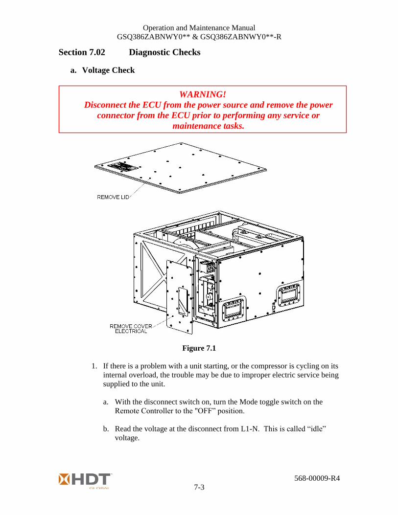
Section 7.02 Diagnostic Checks
a. Voltage Check
Figure 7.1
1. If there is a problem with a unit starting, or the compressor is cycling on its
internal overload, the trouble may be due to improper electric service being
supplied to the unit.
a. With the disconnect switch on, turn the Mode toggle switch on the
Remote Controller to the "OFF” position.
b. Read the voltage at the disconnect from L1-N. This is called “idle”
voltage.
WARNING!
Disconnect the ECU from the power source and remove the power
connector from the ECU prior to performing any service or
maintenance tasks.

Operation and Maintenance Manual
GSQ386ZABNWY0** & GSQ386ZABNWY0**-R
568-00009-R4
7-4
c. Turn the Mode toggle switch on the Remote Controller to the “AUTO”
position. With the compressor running, read the voltage at the
disconnect from L1-N. This is called “running voltage”.
2. If the voltage drops more than 20% between idle and running voltage then
the motors in the unit will overheat. Some common causes of voltage drop
include service transformers that are overloaded, service wiring that is too
small, or too small a generator.
3. If the voltage is correct, then the frequency may not be correct. Running
an ECU with improper voltage and/or frequency can cause compressor and
motor damage.
b. Current Check
1. The nominal load amps for system components are tabulated on the wiring
schematic. They are as follows (for 115V 60Hz):
Compressor (1M) 10.6 amps
Evaporator Fan Motor (2M) 1.9 amps
Condenser Fan Motor (3M) 2.8 amps
Heater Elements (HE1) 13.2 amps (GSQ386ZABNWY0** )
Heater Elements (HE1) 17.3 amps (GSQ386ZABNWY0**-R)
2. Operating current will vary from these nominal values based upon the
operating conditions of the ECU. One can expect the typical operating amps
to be as follows:
Compressor (1M) max load 11.8 amps
Compressor (1M) min load 7.1 amps
Evaporator Fan Motor (2M) 1.9 amps
Condenser Fan Motor (3M) 2.8 amps
Heater Elements (HE1) max 13.8 amps (GSQ386ZABNWY0** )
Heater Elements (HE1) max 18.0 amps (GSQ386ZABNWY0**-R)
3. The maximum power consumed by the ECU in cooling mode with indoor
temperature of 110°F and outdoor temperature of 131F and clean coils is
1,870 watts. A dirty outdoor coil will increase the power consumed by the
ECU. Cooler temperatures will decrease the power consumed by the ECU.
c. Electrical Component Diagnostics
1. To determine the possible failure of electrical components, the diagnostic tests
in Table 7.3 can be used by a qualified technician. A legend of component
abbreviations is provided in Table 7.2.

Operation and Maintenance Manual
GSQ386ZABNWY0** & GSQ386ZABNWY0**-R
568-00009-R4
7-5
Electrical Component Legend
Table 7.2
WARNING!
Heating elements reach high temperatures. Severe burns are possible.
Allow elements to cool before servicing.
WARNING!
Fans and blowers are rotating parts that can cause severe injury.
They may start without warning.
Always disconnect the ECU from its power source prior to servicing.
Do not operate the ECU with panels removed.
DANGER!
Many diagnostic tests require power to be present. Extreme care must
be exercised to avoid DEATH or SERIOUS INJURY. High voltage is
present in the electrical panel.

Operation and Maintenance Manual
GSQ386ZABNWY0** & GSQ386ZABNWY0**-R
568-00009-R4
7-6
Electrical Component Diagnostics
DC Power Supply (PWR1) Power must be connected. Test Power input (L & N), should be 120VAC. Test power output ( + and -), should read 24VDC.
Circuit Breaker (CB1) Power must be disconnected. In the OFF position terminals L1 to L1 & N to N should have no continuity. In the ON position terminals L1 to L1 & N to N should have continuity.
Input Power (J1) Ohm out cable. Color code is Black/White/Green
All Motors
Compressor Motor (1M)
Test each wire to ground for short, this applies to all motors Test wires 12 to 13 & 12 to 14 continuity should be present.
Fan Motor (2M) Test wires 20 to 21 & 20 to 22 Continuity should be present.
Fan Motor (3M) Test wires 30 to 31 & 30 to 32 Continuity should be present.
Contactors (1MS,2MS,3MS,HC1)
1.) Test 1 to 2, 3 to 4 & 5 to 6 continuity should not be present. 2.) A1 to A2 continuity should be present. *** To apply power ensure that tests 1 and 2 are correct.*** 3.) Connect power and check for amp draw. 4.) Ensure you have continuity from 1 to 2, 3 to 4 & 5 to 6.
Selector Switch (SS1) Located on the Remote Control Box
For OFF, AUTO, and FAN modes
OFF: No continuity 1 to 1A or 1B & 2 to 2A or 2B. FAN: Continuity 1 to 1A & 2 to 2A. No continuity 1 to 1B & 2 to 2B. AUTO: Continuity 1 to 1B & 2 to 2B. No continuity 1 to 1A & 2 to 2A
HPC (PS1)
LPC (PS2)
Test terminals 1 and 2, continuity should exist if system pressure is below 325 psi. Test terminals 1 and 2, continuity should exist if system pressure is greater than 35 psi.
Anti short cycle timer part of (TST) Must connect power. Turn unit on to cooling, then off. Turn unit back on to cooling. It should take 2 minutes for the compressor to restart.
Low ambient bypass timer part of (TST)
Must Connect Power. Output T12 will remain on for 2 minutes. (24 volt signal)
Heater Cutout HT1, HT2 Should have continuity from 1 to 2.
Table 7.3

Operation and Maintenance Manual
GSQ386ZABNWY0** & GSQ386ZABNWY0**-R
568-00009-R4
7-7
Figure 7.2
Figure 7.3
Operation and Maintenance Manual
GSQ386ZABNWY0** & GSQ386ZABNWY0**-R
568-00009-R4
7-8
d. Compressor Check
1. The following diagnostic procedure should be used to evaluate whether a
compressor is functioning properly.
a. Verify proper voltage to the ECU.
b. Verify proper indoor and outdoor fan/blower rotation direction.
c. If the compressor will not run, the normal checks of motor winding
continuity and short to ground should be made to determine if the inherent
internal overload motor protector has opened or if an internal short to
ground has developed.
d. If the protector has opened, the compressor must be allowed to cool
sufficiently to allow it to reset.
e. With service gauges connected to suction and discharge pressure fittings,
energize the compressor.
f. If suction pressure falls below normal levels the system is either too low
on charge or there is a flow blockage in the system (refrigerant or air).
g. If suction pressure does not drop and discharge pressure does not rise to
normal levels, the compressor is faulty.

Operation and Maintenance Manual
GSQ386ZABNWY0** & GSQ386ZABNWY0**-R
568-00009-R4
8-1
Chapter 8 Specifications
Dimensions L 26” (27.68" over duct flange) x W 28” x H 16”
(L 660mm (703mm over flange) x W 711mm x H 406mm)
Weight 130 lbs (59 kg)
Less: Electrical Power Cord
Storage Temperature -60°F (-51°C) to +160°F (+71°C)
Operational Ambient
Temperature Range
Heating: -25°F (-31°C) to +90°F (+33°C)
Cooling: +50°F (+10°C) to +135°F (+57.2°C)
Incline Operation: The ECU shall be capable of operation @ 10° incline in any
horizontal direction.
Nominal Cooling
Capacity:
9,000 BTUH Total,
@ 95°FDB OAT. //Evaporator Air Inlet 80°FDB/70°FWB
7, 750 BTUH Total
@ 131°FDB OAT. //Evaporator Air Inlet 90°FDB/75°FWB
Nominal Heating
Capacity:
5,200 BTUH (model GSQ386ZABNWY0**)
6,810 BTUH (model GSQ386ZABNWY0**-R)
POWER
Main Voltage 115/1/50-60VAC
Power Connection (GSQ386ZABNWY0**)
ECU MS3450W18-11P, CABLE MS3106E18-11S (5 Pin)
Power Connection (GSQ386ZABNWY0**-R)
ECU MS3102R20-19P, CABLE MS3106F20-19S (3 Pin)
Main Circuit Breaker CB1- 20 Amp, 2 pole, Hydraulic Type (GSQ386ZABNWY0**)
CB1- 25 Amp, 2 pole, Hydraulic Type (GSQ386ZABNWY0**-R)
8’ Power Cable
(108-00047) #12 AWG, 3 Conductor Cable with MALE, NEMA 5-20P, (GSQ386ZABNWY0**)
8’ Power Cable
(108-00061) #12 AWG, 3 Conductor Cable with MS3106F22-22P (4 Pin), (GSQ386ZABNWY0**)
8’ Power Cable
(108-00132) #8 AWG, 3 Conductor Cable with MS3106F22-22P (4 Pin), (GSQ386ZABNWY0**-R)
Control Voltage 24 VDC
CONDENSER
Compressor Rotary
Airflow 580 SCFM
Condenser Fan Motor Single Speed: 110-130/1/50-60VAC, with Internal Thermal
Overload Protection.
Pressure Relief Valve 550 PSI, Auto Reset.
High Pressure Switch 500 PSI CO, 350 PSI CI
Low Pressure Switch 35 PSI CO, 60 PSI CI
Filter Drier 5 inch3, Solid core filter media.
Sight Glass Moisture Indicator, Viewable from outside the ECU
Table 8.1
Operation and Maintenance Manual
GSQ386ZABNWY0** & GSQ386ZABNWY0**-R
568-00009-R4
8-2
Refrigerant Access Ports
Suction & Discharge Access Valves: ¼ SAE Flare
Connections with Schrader Valve and Cap, accessible from
outside the ECU.
Condenser Coil Aluminum Microchannel coil, Double Row with corrosion
resistant cladding.
EVAPORATOR
Airflow 330 CFM @ .25” ESP
TXV Thermostatic Expansion Valve
Evaporator Coil
Aluminum Finned, 12 Fins per inch, 0.006” thick fin stock,
enhanced copper tube 0.016” thick wall, Face Area 0.67ft2. x
3 rows deep, E-Coating for corrosion protection.
Drain Pan
Drain Pan with Dual Drains to allow for condensate drainage
and ECU operation @ 10° incline in any horizontal direction.
1/2” FPT Drain Connection is located on the side of the unit.
Heating Elements (GSQ386ZABNWY0**)
Elements 420W (+10%/-0) each, Qty. (3)
304 Stainless Steel Construction
Heating Elements (GSQ386ZABNWY0**-R)
Elements 570W (+10%/-0) each, Qty. (3)
304 Stainless Steel Construction
Heater High Limits Qty. (2) Opens 140°F/ Closes 120°F Cut-in
CONTROLS
Contactors IEC Type
DC Power Supply 85-264/1/47-63 VAC Input, 24VDC Output 10A
Thermostat Control with
built in Anti-Short Cycle
and Low Pressure By-
pass
Heating and Cooling Thermostat with remote sensing bulb
located in the return air section of the evaporator. By-passes
the low pressure switch for 2 minutes to allow the system to
start in the Cooling Mode during low ambient conditions. 2
Minute on-delay/on-break timer to control compressor short
cycling.
Mode Toggle Switch Toggle Action Switch, OFF / FAN / AUTO –Modes
Table 8.1 (continued from previous page)
Operation and Maintenance Manual
GSQ386ZABNWY0** & GSQ386ZABNWY0**-R
568-00009-R4
8-3
This page intentionally left blank.
Chapter 9 drawings are organized to span the binding.

Operation and Maintenance Manual
GSQ386ZABNWY0** & GSQ386ZABNWY0**-R
568-00009-R4
9-1
Chapter 9 Reference Drawings
Section 9.01 ECU Electrical Schematic (502-00033)
Figure 9.1.1 Main Electrical Schematic (Drawing continued on next page)
(GSQ386ZABNWY0**-R, 25A Breaker)
(GSQ386ZABNWY0**-R,
18.0A/1.71KW)

Operation and Maintenance Manual
GSQ386ZABNWY0** & GSQ386ZABNWY0**-R
568-00009-R4
9-2
Figure 9.1.2 Main Electrical Schematic (Drawing continued from the previous page)

Operation and Maintenance Manual
GSQ386ZABNWY0** & GSQ386ZABNWY0**-R
568-00009-R4
9-3
Section 9.02 Remote Control Schematic (502-00037)
Figure 9.2 Schematic Remote Control Box

Operation and Maintenance Manual
GSQ386ZABNWY0** & GSQ386ZABNWY0**-R
568-00009-R4
9-4
Section 9.03 ECU Wiring Diagram (514-00022)
Figure 9.3 ECU Wiring Diagram
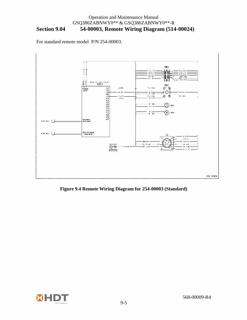
Operation and Maintenance Manual
GSQ386ZABNWY0** & GSQ386ZABNWY0**-R
568-00009-R4
9-5
Section 9.04 54-00003, Remote Wiring Diagram (514-00024)
For standard remote model P/N 254-00003.
Figure 9.4 Remote Wiring Diagram for 254-00003 (Standard)

Operation and Maintenance Manual
GSQ386ZABNWY0** & GSQ386ZABNWY0**-R
568-00009-R4
9-6
Section 9.05 254-00007, Remote Wiring Diagram (514-00029)
For optional bulkhead remote model P/N 254-00007.
This remote has multiple cable lengths in order to be wired thru a bulkhead junction box.
Figure 9.5 Remote Wiring Diagram for 254-00007 (Bulkhead)

Operation and Maintenance Manual
GSQ386ZABNWY0** & GSQ386ZABNWY0**-R
568-00009-R4
9-7
Section 9.06 Refrigeration Schematic (520-00072)
Figure 9.6 Refrigeration Schematic

Operation and Maintenance Manual
GSQ386ZABNWY0** & GSQ386ZABNWY0**-R
568-00009-R4
10-1
Chapter 10 Parts List and Assembly Drawings
Below is the listing of parts sorted by HDT EP, Inc. (HDT) part number. Following these tables are
assembly diagrams that will assist in identifying parts.
NOTE: Parts that have a suffix of “-PM” are finished Matte Sand, per FED-STD-595 COLOR
34094. If you have a unit which is Forest Green, per FED-STD-595 COLOR 34094,
substitute the suffix “-P1” for the listed “-PM” suffix. All of the painted parts listed are
for a matte sand unit.
Parts List, GSQ386ZABNWY0** & GSQ386ZABNWY0**-R,
Sorted by HDT EP, Inc. (HDT) Part Number
HDT Part # DESCRIPTION QTY
010-00141 HEATER ELEMENT- 420W (GSQ386ZABNWY0**) 3
010-00206 HEATER ELEMENT- 570W (GSQ386ZABNWY0**-R) 3
011-00132 T-STAT- SNAP DISC 2
011-00149 SWITCH- LOW PRESSURE 1
011-00222 TOGGLE SWITCH 3 POS 1
011-00223 SWITCH HIGH PRESSURE 1
011-00224 LED GREEN 2
013-00179S SUPPRESSOR 4
013-00235 KICKSTART 1
013-00377, See Note* CAPACITOR 30MF (Used with Condenser & Original Evaporator Blower)
1
013-00378 CAPACITOR 25MF 1
013-00389, See Note* CAPACITOR 17.5MF (Used with New Evaporator Blower) 1
Note*
013-00389 REPLACES 1 OF 2, 013-00377 PER UNIT MODIFICATION BEGINS WITH UNIT S.N. GSQ30228 013-00377 IS USED WITH BLOWER 071-00092 013-00389 IS USED WITH BLOWER 071-00104
-
013-00895 CONTACTOR 4
014-00069 24VDC POWER SUPPLY 1
014-00069-1 POWER SUPPLY MOUNTING BRACKET 1
015-00066 CURRENT SENSING SW 1
015-00077 THERMISTER PROBE 1
015-00117 TEMPERATURE CONTROL 1
015-00119 REMOTE SITE CONTROLLER 1
015-00120 HUMIDITY & TEMP TRANSMITTER 1
016-00368-LD CIRCUIT BREAKER- 20 AMP (LONG DELAY), (GSQ386ZABNWY0**)
1
016-00552 CIRCUIT BREAKER- 25 AMP (LONG DELAY), (GSQ386ZABNWY0**-R)
1
017-00037 GROUND LUG 1
017-00102C CLAMP 1
017-00102PM PLUG RECEPTACLE 1
017-00102RF RECEPTACLE 1
017-00113N NUT 1
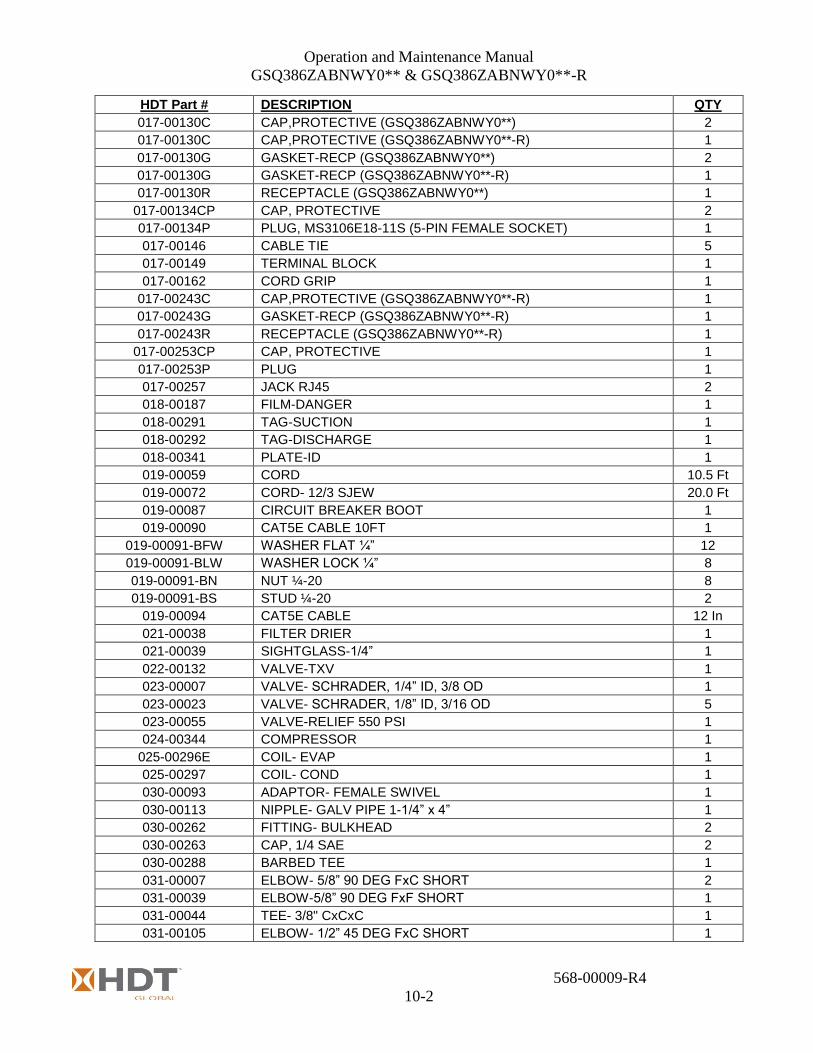
Operation and Maintenance Manual
GSQ386ZABNWY0** & GSQ386ZABNWY0**-R
568-00009-R4
10-2
HDT Part # DESCRIPTION QTY
017-00130C CAP,PROTECTIVE (GSQ386ZABNWY0**) 2
017-00130C CAP,PROTECTIVE (GSQ386ZABNWY0**-R) 1
017-00130G GASKET-RECP (GSQ386ZABNWY0**) 2
017-00130G GASKET-RECP (GSQ386ZABNWY0**-R) 1
017-00130R RECEPTACLE (GSQ386ZABNWY0**) 1
017-00134CP CAP, PROTECTIVE 2
017-00134P PLUG, MS3106E18-11S (5-PIN FEMALE SOCKET) 1
017-00146 CABLE TIE 5
017-00149 TERMINAL BLOCK 1
017-00162 CORD GRIP 1
017-00243C CAP,PROTECTIVE (GSQ386ZABNWY0**-R) 1
017-00243G GASKET-RECP (GSQ386ZABNWY0**-R) 1
017-00243R RECEPTACLE (GSQ386ZABNWY0**-R) 1
017-00253CP CAP, PROTECTIVE 1
017-00253P PLUG 1
017-00257 JACK RJ45 2
018-00187 FILM-DANGER 1
018-00291 TAG-SUCTION 1
018-00292 TAG-DISCHARGE 1
018-00341 PLATE-ID 1
019-00059 CORD 10.5 Ft
019-00072 CORD- 12/3 SJEW 20.0 Ft
019-00087 CIRCUIT BREAKER BOOT 1
019-00090 CAT5E CABLE 10FT 1
019-00091-BFW WASHER FLAT ¼” 12
019-00091-BLW WASHER LOCK ¼” 8
019-00091-BN NUT ¼-20 8
019-00091-BS STUD ¼-20 2
019-00094 CAT5E CABLE 12 In
021-00038 FILTER DRIER 1
021-00039 SIGHTGLASS-1/4” 1
022-00132 VALVE-TXV 1
023-00007 VALVE- SCHRADER, 1/4” ID, 3/8 OD 1
023-00023 VALVE- SCHRADER, 1/8” ID, 3/16 OD 5
023-00055 VALVE-RELIEF 550 PSI 1
024-00344 COMPRESSOR 1
025-00296E COIL- EVAP 1
025-00297 COIL- COND 1
030-00093 ADAPTOR- FEMALE SWIVEL 1
030-00113 NIPPLE- GALV PIPE 1-1/4” x 4” 1
030-00262 FITTING- BULKHEAD 2
030-00263 CAP, 1/4 SAE 2
030-00288 BARBED TEE 1
031-00007 ELBOW- 5/8” 90 DEG FxC SHORT 2
031-00039 ELBOW-5/8” 90 DEG FxF SHORT 1
031-00044 TEE- 3/8" CxCxC 1
031-00105 ELBOW- 1/2” 45 DEG FxC SHORT 1

Operation and Maintenance Manual
GSQ386ZABNWY0** & GSQ386ZABNWY0**-R
568-00009-R4
10-3
HDT Part # DESCRIPTION QTY
031-00106 ELBOW- 1/2” 90 DEG FxC SHORT 1
031-00108 ADAPTER- 5/8 Cx3/8 FIP 1
031-00132 ELBOW- 1/4" 90 DEG FxC SHORT RAD 2
031-00152 ADAPTER-DROP- 1/2 Cx1/2 FPT 1
031-00177 ELBOW- 1/2” 90 DEG CxC LONG 1
031-00211 REDUCER-FxC, 3/8x 1/4 1
031-00212 ELBOW- 1/4” 90 DEG FxC LONG 1
034-04000 HOSE- #4 23.75 In
034-04001 CAGE- #4 4
034-04002 CLIP- #4 4
034-04003 FITTING, STRAIGHT- #4 1
034-04004 FITTING, 90 DEG- #4 2
034-04005 FITTING, 45 DEG- #4 1
053-00012-PM HANDLE, RECESSED 4
056-00002 CLAMP- GEAR 3/4" 1
056-00003 CLAMP- HOSE, 4-1/2" - 6-1/2" (GSQ386ZABNWY0**) 1
056-00015 CLAMP- HOSE 1/2" - 1-1/16" 6
056-00060 CLAMP-LOOP- 0.38 DIA. 5
056-00062 CLAMP-LOOP- 0.625 DIA. 1
056-00063 CLAMP-LOOP- 0.75 DIA 1
056-00073 CLAMP-LOOP, 1.75 DIA 3
056-00074 CLAMP-LOOP, 2.00 DIA 1
056-00083-BAND CLAMP- BAND, 4.78 - 5.09" (GSQ386ZABNWY0**-R) 1
059-00051 STUD 3/8-16 x 1.5 3
059-00279-025 SPACER STANDOFFS 1/4" 6
060-00008 GROMMET- 5/8 ID 1
060-00038 GROMMET- 3/8 ID 1
060-00047 GROMMET- 1 ID 2
060-00049 GROMMET- 1/8 ID 1
060-00057 GROMMET- 1/2 ID 2
060-00060 GROMMET- 1 1/8 ID 1
060-00067 GROMMET-RED SILICON 0.91" 2
060-00068 GROMMET-RED SILICON 1.14" 6
060-00073 GROMMET- 1/4 ID 1
067-00004 REFRIGERANT- R-407C 32 Oz
071-00092, See Note** BLOWER- MOTORIZED (Condenser & Original Evaporator Blower)
1
071-00104, See Note** BLOWER- MOTORIZED (New Evaporator Blower) 1
Note** 071-00104 REPLACES 1 OF 2, 071-00092 PER UNIT MODIFICATION BEGINS WITH UNIT S.N. GSQ30228
-
100-00857-B COMPRESSOR STANDOFF 3
108-00061 CABLE ASSY-POWER-CABLE-MAIN (GSQ386ZABNWY0**) 1
108-00062 CABLE ASSY-POWER-MAIN INTERNAL (GSQ386ZABNWY0**) 1
108-00063 CABLE ASSEMBLY-CONTROL INTERNAL 1
108-00075 CABLE ASSY- INTERNAL ETHERNET 2
108-00130 CABLE ASSY-POWER-MAIN INTERNAL (GSQ386ZABNWY0**-R) 1
108-00132 CABLE ASSY-POWER-CABLE-MAIN (GSQ386ZABNWY0**-R) 1
230-00033BJ-PM BRACKET (GSQ386ZABNWY0**) 1

Operation and Maintenance Manual
GSQ386ZABNWY0** & GSQ386ZABNWY0**-R
568-00009-R4
10-4
HDT Part # DESCRIPTION QTY
230-00033BP BRACKET, STAINLESS STEEL (GSQ386ZABNWY0**-R) 1
230-00037BA-PM FRAME - LOWER 1
230-00037BB-PM FRAME - UPPER 1
230-00037BC-PM COVER - TOP 1
230-00037BD-PM COVER - LEFT 1
230-00037BE-PM COVER - RIGHT 1
230-00037BF-PM COVER - ELECTRICAL ACCESS 1
230-00037BG-PM ELECTRICAL PANEL 1
230-00037BH-PM OPERATOR PANEL, (GSQ386ZABNWY0**) 1
230-00037BJ-PM SUPPORT - TXV 1
230-00037BN-PM POTENTIOMETER MOUNTING BRACKET 1
230-00037CH-PM BRACKET - FILTER/DRYER 1
230-00037DA-PM BULKHEAD - EVAP - ELEC 1
230-00037DB-PM BULKHEAD - EVAP - COND 1
230-00037DC-PM BULKHEAD - EVAP 1
230-00037DD-PM See Note***
MOUNTING PLATE - BLOWER (Used with Condenser & Original Evaporator Blower)
1
230-00037DF-PM PLENUM - RETURN AIR 1
230-00037DG-PM BRACKET - SENSOR 1
230-00037DJ-PM PLENUM - SUPPLY AIR 1
230-00037DK-PM SPACER - COND BULKHEAD 1
230-00037DL-PM RETAINER - COND BULKHEAD 1
230-00037DM-PM TEST PORT RECESS 1
230-00037DN-PM BULKHEAD - CONDENSER 1
230-00037DR-PM CHANNEL-ELEC 2
230-00037DS-PM RETAINER CLIP 4
230-00037DT-PM See Note***
MOUNTING PLATE – BLOWER (GSQ386ZABNWY0**) (Used with New Evaporator Blower)
1
Note***
230-00037DT REPLACES 1 OF 2, 230-00037DD PER UNIT MODIFICATION BEGINS WITH UNIT S.N. GSQ30228 230-00037DD IS USED WITH BLOWER 071-00092 230-00037DT IS USED WITH BLOWER 071-00104
-
230-00037DT-S MOUNTING PLATE – BLOWER, SS (GSQ386ZABNWY0**-R) 1
230-00037FE-PM DRAIN PAN WELDED 1
230-00037FB-PM BRACKET 1
230-00037JE-PM COIL FRAME TOP-BOTTOM 2
230-00037JF-PM COIL FRAME-RIGHT 1
230-00037JG-PM COIL FRAME-LEFT 1
230-00037JH-PM BULKHEAD - COND - ELEC 1
230-00037JJ-PM RETAINER - COND FRAME 1
230-0BA37BH-PM OPERATOR PANEL, (GSQ386ZABNWY0**-R) 1
254-00003A-PB BOX CONTROL 1
254-00003B-PB COVER BOX 1
254-00003C-PB FRONT PANEL 1

Operation and Maintenance Manual
GSQ386ZABNWY0** & GSQ386ZABNWY0**-R
568-00009-R4
10-5
Figure 10.1.1, Main Assembly (230-00037-AM), 1 of 6
Parts List, Main Assembly (230-00037-AM), 1 of 6, Ref. Figure 10.1.1
Item HDT Part # DESCRIPTION QTY
1 230-00037BC-PM COVER-TOP 1
2 230-00037DF-PM PLENUM-RETURN AIR 1
3 108-00063 CABLE ASSY-CONTROL 1
4 015-00120 HUMIDITY & TEMP TRANSMITTER 1
5 230-00037DG-PM BRACKET - SENSOR 1
6 230-00037BB-PM FRAME - UPPER 1
7 230-00037DJ-PM PLENUM-SUPPLY AIR 1
8 053-00012-PM HANDLE 4
9 230-00037BD-PM COVER - LEFT 1
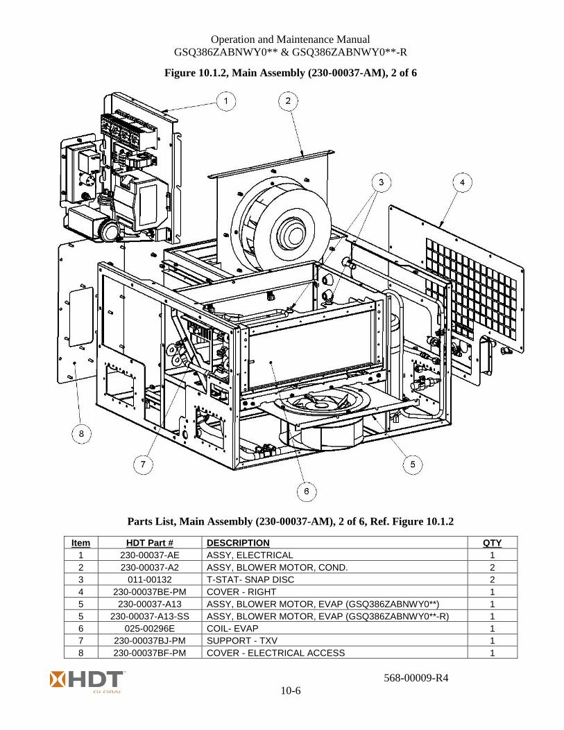
Operation and Maintenance Manual
GSQ386ZABNWY0** & GSQ386ZABNWY0**-R
568-00009-R4
10-6
Figure 10.1.2, Main Assembly (230-00037-AM), 2 of 6
Parts List, Main Assembly (230-00037-AM), 2 of 6, Ref. Figure 10.1.2
Item HDT Part # DESCRIPTION QTY
1 230-00037-AE ASSY, ELECTRICAL 1
2 230-00037-A2 ASSY, BLOWER MOTOR, COND. 2
3 011-00132 T-STAT- SNAP DISC 2
4 230-00037BE-PM COVER - RIGHT 1
5 230-00037-A13 ASSY, BLOWER MOTOR, EVAP (GSQ386ZABNWY0**) 1
5 230-00037-A13-SS ASSY, BLOWER MOTOR, EVAP (GSQ386ZABNWY0**-R) 1
6 025-00296E COIL- EVAP 1
7 230-00037BJ-PM SUPPORT - TXV 1
8 230-00037BF-PM COVER - ELECTRICAL ACCESS 1
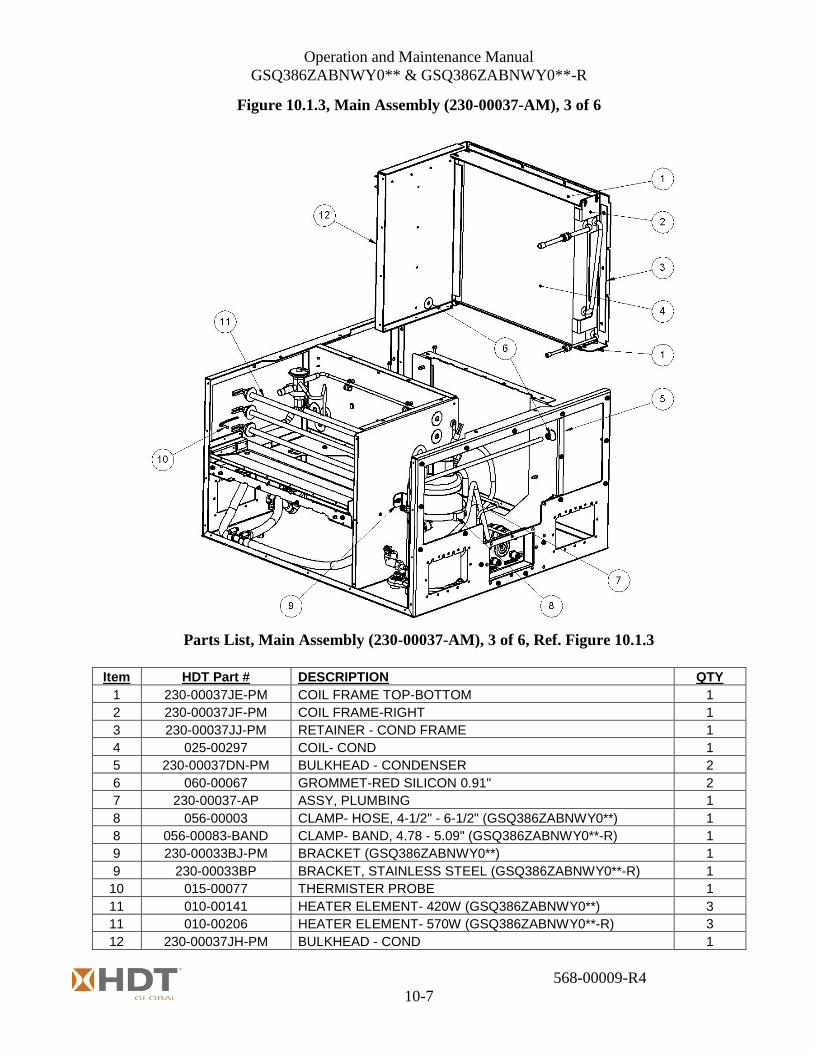
Operation and Maintenance Manual
GSQ386ZABNWY0** & GSQ386ZABNWY0**-R
568-00009-R4
10-7
Figure 10.1.3, Main Assembly (230-00037-AM), 3 of 6
Parts List, Main Assembly (230-00037-AM), 3 of 6, Ref. Figure 10.1.3
Item HDT Part # DESCRIPTION QTY
1 230-00037JE-PM COIL FRAME TOP-BOTTOM 1
2 230-00037JF-PM COIL FRAME-RIGHT 1
3 230-00037JJ-PM RETAINER - COND FRAME 1
4 025-00297 COIL- COND 1
5 230-00037DN-PM BULKHEAD - CONDENSER 2
6 060-00067 GROMMET-RED SILICON 0.91" 2
7 230-00037-AP ASSY, PLUMBING 1
8 056-00003 CLAMP- HOSE, 4-1/2" - 6-1/2" (GSQ386ZABNWY0**) 1
8 056-00083-BAND CLAMP- BAND, 4.78 - 5.09" (GSQ386ZABNWY0**-R) 1
9 230-00033BJ-PM BRACKET (GSQ386ZABNWY0**) 1
9 230-00033BP BRACKET, STAINLESS STEEL (GSQ386ZABNWY0**-R) 1
10 015-00077 THERMISTER PROBE 1
11 010-00141 HEATER ELEMENT- 420W (GSQ386ZABNWY0**) 3
11 010-00206 HEATER ELEMENT- 570W (GSQ386ZABNWY0**-R) 3
12 230-00037JH-PM BULKHEAD - COND 1

Operation and Maintenance Manual
GSQ386ZABNWY0** & GSQ386ZABNWY0**-R
568-00009-R4
10-8
Figure 10.1.4, Main Assembly (230-00037-AM), 4 of 6
Parts List, Main Assembly (230-00037-AM), 4 of 6, Ref. Figure 10.1.4
Item HDT Part # DESCRIPTION QTY
1 230-00037BA-PM FRAME - LOWER 1
2 230-00037DR-PM CHANNEL-ELEC. PANEL 1
3 230-00037DL-PM RETAINER - COND BULKHEAD 1
4 230-00037DK-PM SPACER - COND BULKHEAD 1
5 030-00262 FITTING- BULKHEAD-1/4SAE FLARE 2
6 230-00037DM-PM TEST PORT RECESS 1
7 030-00263 CAP, 1/4 SAE PLASTIC W/STRAP 2
8 060-00060 GROMMET- 1 1/8 ID 1
9 021-00039 SIGHTGLASS- 1/4" SWEAT 1
10 056-00060 CLAMP-LOOP- 0.38” DIA 2
11 056-00063 CLAMP-LOOP- 0.75 DIA 1

Operation and Maintenance Manual
GSQ386ZABNWY0** & GSQ386ZABNWY0**-R
568-00009-R4
10-9
Figure 10.1.5, Main Assembly (230-00037-AM), 5 of 6
Parts List, Main Assembly (230-00037-AM), 5 of 6, Ref. Figure 10.1.5
Item HDT Part # DESCRIPTION QTY
1 060-00068 GROMMET-RED SILICON 1.14" 5
2 230-00037DB-PM BULKHEAD - EVAP - COND 1
3 230-00037DC-PM BULKHEAD - EVAP 1
4 230-00037DS-PM RETAINER CLIP 4
5 230-00037DA-PM BULKHEAD - EVAP - ELEC 1
6 056-00060 CLAMP-LOOP- 0.38” DIA 2
7 060-00008 GROMMET- 5/8” ID 1
8 060-00073 GROMMET- 1/4” ID 1

Operation and Maintenance Manual
GSQ386ZABNWY0** & GSQ386ZABNWY0**-R
568-00009-R4
10-10
Figure 10.1.6, Drain Pan Assembly (230-00037-AM), 6 of 6
Parts List, Drain Pan Assembly (230-00037-AM), 6 of 6, Ref. Figure 10.1.6
Item HDT Part # DESCRIPTION QTY
1 230-00037FE-PM DRAIN PAN 1
2 FS-00498 TUBING-.500 ID .750 OD X 0.125 WALL 1
3 030-00288 BARBED TEE 1/2"x1/2"x1/2" 1
4 056-00015 CLAMP- HOSE 1/2" - 1-1/16" 6
5 031-00152 ADAPTER-DROP- 1/2 Cx1/2 FP 1
6 031-00007 ELBOW- 5/8" 90 DEG FxC SHORT RAD 2
7 031-00108 ADAPTER- 5/8 Cx3/8 FIP 1
8 030-00113 BARBED 90EL 1/2"x3/8"MPT 1
9 031-00039 ELBOW- 5/8" 90 DEG FxF SHORT RAD 1

Operation and Maintenance Manual
GSQ386ZABNWY0** & GSQ386ZABNWY0**-R
568-00009-R4
10-11
Figure 10.2, Blower Motor Condenser Assembly (230-00037-A2)
Parts List, Blower Motor Condenser Assembly (230-00037-A2), Ref. Figure 10.2
Item HDT Part # DESCRIPTION QTY
1 FS-00383 SCREW- #10-24 x 3/4" SLOT HEX 8
2 071-00092 BLOWER- MOTORIZED 1
3 230-00037DD-PM MOUNTING PLATE - BLOWER 1
4 FS-00341 RIVNUT-HEX 10-24 8

Operation and Maintenance Manual
GSQ386ZABNWY0** & GSQ386ZABNWY0**-R
568-00009-R4
10-12
Figure 10.3A, Blower Motor Evaporator Assembly (230-00037-A13)
Model GSQ386ZABNWY0**
Parts List, Blower Motor Evaporator (230-00037-A13), Ref. Figure 10.3A
Model GSQ386ZABNWY0**
Item HDT Part # DESCRIPTION QTY
1 FS-00383 SCREW- #10-24 x 3/4" SLOT HEX 4
2 071-00092 See Note**
BLOWER- MOTORIZED (**FOR SERIAL NUMBERS PRIOR TO GSQ30228)
1
2 071-00104 See Note**
BLOWER- MOTORIZED (**BEGINING WITH SERIAL NUMBER GSQ30228)
1
Note** 071-00104 REPLACES 1 OF 2, 071-00092 PER UNIT MODIFICATION BEGINS WITH UNIT S.N. GSQ30228
-
3 230-00037DD-PM
See Note*** MOUNTING PLATE - BLOWER (***FOR SERIAL NUMBERS PRIOR TO GSQ30228)
1
3 230-00037DT-PM
See Note*** MOUNTING PLATE - BLOWER (***BEGINING WITH SERIAL NUMBER GSQ30228)
1
Note***
230-00037DT REPLACES 1 OF 2, 230-00037DD PER UNIT MODIFICATION BEGINS WITH UNIT S.N. GSQ30228 230-00037DD IS USED WITH BLOWER 071-00092 230-00037DT IS USED WITH BLOWER 071-00104
-
4 FS-00341 RIVNUT-HEX 10-24 4

Operation and Maintenance Manual
GSQ386ZABNWY0** & GSQ386ZABNWY0**-R
568-00009-R4
10-13
Figure 10.3A, Blower Motor Evaporator Assembly (230-00037-A13-SS)
Model GSQ386ZABNWY0**-R
Parts List, Blower Motor Evaporator (230-00037-A13-SS), Ref. Figure 10.3B
Model GSQ386ZABNWY0**-R
Item HDT Part # DESCRIPTION QTY
1 FS-00383 SCREW- #10-24 x 3/4" SLOT HEX 4
2 071-00104 BLOWER- MOTORIZED 1
3 230-00037DT-S MOUNTING PLATE – BLOWER, STAINLESS STEEL 1
4 FS-00341 RIVNUT-HEX 10-24 4

Operation and Maintenance Manual
GSQ386ZABNWY0** & GSQ386ZABNWY0**-R
568-00009-R4
10-14
Figure 10.4, Control Panel Assembly (230-00037-A7)
Parts List, Control Panel Assembly (230-00037-A7), Ref. Figure 10.4
Item HDT Part # DESCRIPTION QTY
1 016-00368-LD CIRCUIT BREAKER (LONG DELAY), (GSQ386ZABNWY0**) 1
1 016-00552 CIRCUIT BREAKER (LONG DELAY), (GSQ386ZABNWY0**-R) 1
2 FS-00415 NYLOCK NUT, SS, 4-40 4
3 019-00091-B ASSY, 1/4-20, BRONZE GROUND STUD 1
4 230-00037BH-PM OPERATOR PANEL, (GSQ386ZABNWY0**) 1
4 230-0BA37BH-PM OPERATOR PANEL, (GSQ386ZABNWY0**-R) 1
5 017-00130C PROTECTIVE CAP RECEPTACLE, (GSQ386ZABNWY0**) 1
5 017-00243C PROTECTIVE CAP RECEPTACLE, (GSQ386ZABNWY0**-R) 1
6 017-00130R BOX MTG RECEPTACLE (108-00062), (GSQ386ZABNWY0**) 1
6 017-00243R BOX MTG RECEPTACLE (108-00130), (GSQ386ZABNWY0**-R) 1
7 017-00130G GASKET AMPHENOL, (GSQ386ZABNWY0**) 1
7 017-00243G GASKET AMPHENOL, (GSQ386ZABNWY0**-R) 1
8 FS-00460 SCREW- #6-32 x 1/2" SOCKET HD CAP SCREW 4
9 4-40 x 500 SCREW- #4-40 x 1/2" PHIL 4
10 019-00087 BOOT - USE WITH 016-00368-LD OR 016-00552 1

Operation and Maintenance Manual
GSQ386ZABNWY0** & GSQ386ZABNWY0**-R
568-00009-R4
10-15
Figure 10.5.1, Electrical Panel Assembly (230-00037-AE), 1 of 2

Operation and Maintenance Manual
GSQ386ZABNWY0** & GSQ386ZABNWY0**-R
568-00009-R4
10-16
Parts List, Electrical Panel Assembly (230-00037-AE), 1 of 2, Ref. Figure 10.5.1
Item HDT Part # DESCRIPTION QTY
1 230-00037BG ELECTRICAL PANEL 1
2 FS-00375 NYLOCK NUT, SS, 10-24 2
3 056-00074 CLAMP - LOOP - 2 DIA 1
4 FS-00016 10-24 X 5/8" SCREW 2
5 FS-00557 SCREW- #8-32 X 1/2" SOCKET CAP 4
6 014-00069 DC POWER SUPPLY 1
7 013-00235 HARDSTART 110/115/120V-1PH-60HZ 1
8 230-00037-A7 OPERATOR PANEL ASSEMBLY 1
9 FS-00341 RIVNUT-HEX 10-24 14
10 6-32 x .625 SCREW- #6-32 x 5/8" SOCKET HD CAP SCREW 8
11 1-W-6 FLATWASHER #6; 1-W-6 8
12 013-00895 CONTACTOR - 24V DC 4

Operation and Maintenance Manual
GSQ386ZABNWY0** & GSQ386ZABNWY0**-R
568-00009-R4
10-17
Figure 10.5.2, Electrical Panel Assembly (230-00037-AE), 2 of 2
Operation and Maintenance Manual
GSQ386ZABNWY0** & GSQ386ZABNWY0**-R
568-00009-R4
10-18
Parts List, Electrical Panel Assembly (230-00037-AE), 2 of 2, Ref. Figure 10.5.2
Item HDT Part # DESCRIPTION QTY
13 FS-00266H12 RIVNUT-HEX 6-32 8
14 015-00117 TEMPERATURE CONTROL BOARD 1
15 015-00066 CURRENT SENSING 1
16 FS-00712 FLATWASHER #10; 1-W-10 2
17 FS-00382 SCREW- #10-24 x 1/2" SLOT HEX 2
18 FS-00340 RIVNUT-HEX 8-32 6
19 013-00378 CAPACITOR, 25uf 1
20 FS-00381 SCREW- #10-24 x 5/8" SLOT HEX 3
21 015-00117-POT POTENTIOMETER 1
22 FS-00015 RIVET- 1/8 SS , 0.187 GRIP 2
23 230-00037BN POTENTIOMETER MOUNTING BRACKET 1
24 056-00073 CLAMP - LOOP - 1.125 DIA 3
25 013-00377 See Note*
CAPACITOR, 30uf, EVAPORATOR BLOWER (CAP2) (*FOR SERIAL NUMBERS PRIOR TO GSQ30228)
1
25 013-00389 See Note*
CAPACITOR, 17.5uf, EVAPORATOR BLOWER (CAP2) (*BEGINING WITH SERIAL NUMBER GSQ30228)
1
Note*
013-00389 REPLACES 1 OF 2, 013-00377 PER UNIT MODIFICATION BEGINS WITH UNIT S.N. GSQ30228 013-00377 IS USED WITH BLOWER 071-00092 013-00389 IS USED WITH BLOWER 071-00104
-
26 013-00377 CAPACITOR, 30uf, EVAPORATOR BLOWER (CAP3) 1
27 8-32 X 1.000 SCREW- #8-32 X 1" SOCKET CAP 2
28 FS-00776 WASHER, S.S. FOR #8 FASTENER 2

Operation and Maintenance Manual
GSQ386ZABNWY0** & GSQ386ZABNWY0**-R
568-00009-R4
10-19
Figure 10.6, Electrical Remote Assembly (254-00003 & 254-00007)
Parts List, Electrical Remote Assembly (254-00003 & 254-00007), Ref. Figure 10.6
Item HDT Part # DESCRIPTION QTY
1 254-00003B-PB COVER BOX 1
2 FS-00042 SCREW- #8-32 x 1/2" PHIL 14
3 019-00091-B ASSY, 1/4-20, BRONZE GROUND STUD 1
4 4-INT-25 STARWASHER 4-INT-25 1
5 015-00119 REMOTE SITE CONTROLLER 1
6 FS-00415 NYLOCK NUT, SS, 4-40 6
7 4-40 x 625 SCREW- #4-40 x .750" 6
8 059-00279-025 SPACER NYLON 1/4" 6
9 017-00261 LAN PLUG 2
10 011-00222 SWITCH - TOGGLE 1
11 254-00003C-PB FRONT PANEL 1
12 011-00224 GREEN - LIGHT EMITTING DIODE 2
13 FS-00340 RIVNUT-HEX 8-32 14
14 254-00003A-PB BOX CONTROL 1
15 017-00149 TERMINAL BLOCK 1
16 017-00113N LOCKNUT 3/4" PLASTIC 1
17 017-00162 CORD GRIP 3/4" .45-.71 1

Operation and Maintenance Manual
GSQ386ZABNWY0** & GSQ386ZABNWY0**-R
568-00009-R4
10-20
Figure 10.7.1, Electrical Remote Assembly (254-00003-10)
Parts List, Electrical Remote Assembly, (254-00003-10), Ref. Figure 10.7.1
Item HDT Part # DESCRIPTION QTY
1 108-00064-10 CABLE ASSEMBLY-CONTROL, 10 FT LONG 1
Figure 10.7.2, Electrical Remote Assembly (254-00007)
Parts List, Electrical Remote Assembly, (254-00007), Ref. Figure 10.7.2
Item HDT Part # DESCRIPTION QTY
1 108-00084 CABLE ASSEMBLY-CONTROL, 4 FT LONG 1
2 Not Supplied THRU BULKHEAD RECEPTACLE REF
3 108-00085 CABLE ASSEMBLY-CONTROL, 5 FT LONG 1

Operation and Maintenance Manual
GSQ386ZABNWY0** & GSQ386ZABNWY0**-R
568-00009-R4
10-21
Figure 10.8, Plumbing Assembly (230-00037-AP)
Parts List, Plumbing Assembly, (230-00037-AP), Ref. Figure 10.8
Item HDT Part # DESCRIPTION QTY
1 022-00132 VALVE-TXV 1
2 230-00037-APC PLUMBING ASSY RUN C 1
3 230-00037-APE SUCTION HOSE ASSEMBLY 1
4 230-00037-APA PLUMBING ASSY RUN A 1
5 230-00037-APF DISCHARGE HOSE ASSEMBLY 1
6 023-00055 PRESS RELIEF VALVE 1
7 011-00223 PRESSURE SWITCH - HIGH 1
8 230-00037-APD PLUMBING ASSY RUN D 1
9 024-00344 COMPRESSOR 1
10 011-00149 PRESSURE SWITCH - LOW 1
11 230-00037-APB PLUMBING ASSY RUN B 1
- 100-00857-B COMPRESSOR STANDOFF (NOT SHOWN) 3

Operation and Maintenance Manual
GSQ386ZABNWY0** & GSQ386ZABNWY0**-R
568-00009-R4
10-22
Figure 10.9, Plumbing Sub-Assembly "A", (230-00037-APA)
Parts List, Plumbing Sub-Assembly "A", (230-00037-APA), Ref. Figure 10.9
Item HDT Part # DESCRIPTION QTY
1 021-00039 SIGHTGLASS 1
2 031-00132 STREET ELL SHORT RAD 31/4 F X C 2
3 021-00038 FILTER DRIER 1
4 ACR-2-SAT 1/4" OD X 9-1/2" LG COPPER TUBE 1
Figure 10.10, Plumbing Sub-Assembly "B", (230-00037-APB)
Parts List, Plumbing Sub-Assembly "B", (230-00037-APB), Ref. Figure 10.10
Item HDT Part # DESCRIPTION QTY
1 ACR-3-SAT 1/4" OD X 35-5/8" LG COPPER TUBE 1
2 031-00212 90 DEG ELBOW, 1/4" FxC LR 1
3 031-00211 REDUCER 3/8" TO 1/4" FxC 1

Operation and Maintenance Manual
GSQ386ZABNWY0** & GSQ386ZABNWY0**-R
568-00009-R4
10-23
Figure 10.11, Plumbing Sub-Assembly "C", (230-00037-APC)
Parts List, Plumbing Sub-Assembly "C", (230-00037-APC), Ref. Figure 10.11
Item HDT Part # DESCRIPTION QTY
1 031-00177 ELBOW - 1/2" 90 DEG CxC L.R. 1
2 031-00105 45 STREET ELL 1/2"OD FTG TO COPPER 1
3 ACR-6-SAT 1/2" OD X 4-1/2" LG COPPER TUBE 1
4 031-00106 ELBOW - 1/2" 90 DEG FxC L.R. 1
5 023-00023 VALVE-SCHRADER - STEPPED 2
6 ACR-7-SAT 1/2" OD X 20-21/32" LG COPPER TUBE 1
Figure 10.12, Plumbing Sub-Assembly "D", (230-00037-APD)
Parts List, Plumbing Sub-Assembly "D", (230-00037-APD), Ref. Figure 10.12
Item HDT Part # DESCRIPTION QTY
1 ACR-5-SAT 3/8" OD X 49-1/2" LG COPPER TUBE 1
2 023-00023 VALVE-SCHRADER - STEPPED 3

Operation and Maintenance Manual
GSQ386ZABNWY0** & GSQ386ZABNWY0**-R
568-00009-R4
10-24
Figure 10.13, Plumbing Sub-Assembly "E", (230-00037-APE)
Parts List, Plumbing Sub-Assembly "E", (230-00037-APE), Ref. Figure 10.13
Item HDT Part # DESCRIPTION QTY
1 034-04005 #4 45 DEG ELBOW EZ CLIP 1
2 034-04001 CAGE-#4 2
3 034-04002 CLIP-#4 2
4 034-04000 HOSE- #4 1
5 034-04004 #4 90 DEG ELBOW EZ CLIP 1
Figure 10.14, Plumbing Sub-Assembly "F", (230-00037-APF)
Parts List, Plumbing Sub-Assembly "F", (230-00037-APF), Ref. Figure 10.14
Item HDT Part # DESCRIPTION QTY
1 034-04000 HOSE- #4 1
2 034-04002 CLIP-#4 2
3 034-04003 #4 STRAIGHT EZ CLIP FEMALE 1
4 034-04001 CAGE-#4 2
5 034-04004 #4 90 DEG ELBOW EZ CLIP 1

Operation and Maintenance Manual
GSQ386ZABNWY0** & GSQ386ZABNWY0**-R
568-00009-R4
10-25
Figure 10.15, External Power Cable Assembly, (108-00061)
Used with model GSQ386ZABNWY0**
Parts List, External Power Cable Assembly, (108-00061), Ref. Figure 10.15
Item HDT Part # DESCRIPTION QTY
1 017-00134CP CAP,PROTECTIVE PLUG 1
2 017-00134P PLUG, MS3106E18-11S (5-PIN FEMALE SOCKET), TO ECU 1
3 019-00072 CORD SOW #12-3,1431 UL RATED 8 ft
4 017-00253P PLUG, MS3106F22-22P (4-PIN MALE PINS), TO POWER 1
5 017-00253CP CAP,PROTECTIVE PLUG 1
Figure 10.16, External Power Cable Assembly, (108-00047)
(Optional) Used with model GSQ386ZABNWY0**
Parts List, External Power Cable Assembly, (108-00047), Ref. Figure 10.16
Item HDT Part # DESCRIPTION QTY
1 019-00072 CORD SOW #12-3,1431 UL RATED 10.5ft
2 017-00134P PLUG, MS3106E18-11S (5-PIN FEMALE SOCKET), TO ECU 1
3 017-00124CP CAP,PROTECTIVE PLUG 1
4 017-00184 120V AC PLUG NEMA 5-20, TO POWER 1

Operation and Maintenance Manual
GSQ386ZABNWY0** & GSQ386ZABNWY0**-R
568-00009-R4
10-26
Figure 10.17, External Power Cable Assembly, (108-00132)
Used with model GSQ386ZABNWY0**-R
Parts List, External Power Cable Assembly, (108-00132), Ref. Figure 10.17
Item HDT Part # DESCRIPTION QTY
1 017-00243PC CAP,PROTECTIVE PLUG 1
2 017-00243P PLUG, MS3106F20-19S (3-PIN FEMALE SOCKET), TO ECU 1
3 066-00028 CABLE, #8-3 8 ft
4 017-00253P PLUG, MS3106F22-22P (4-PIN MALE PINS), TO POWER 1
5 017-00253CP CAP,PROTECTIVE PLUG 1

Operation and Maintenance Manual
GSQ386ZABNWY0** & GSQ386ZABNWY0**-R
568-00009-R4
10-27
This page intentionally left blank.


