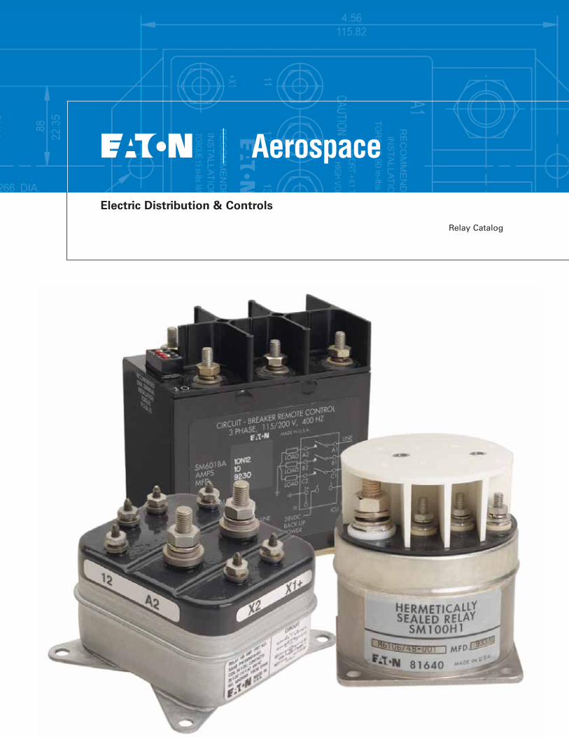
Relay Catalog
Electric Distribution & Controls
Making the Best Better
Traditional aerospace component suppliers are being asked to assume even greater levels ofresponsibility. One trend is thatcomponent manufacturers arebeing asked to increase theirsubsystem integration capabilityto better serve the consolidatingglobal Tier 1 Systems Integratorsand Airframe Manufacturers.Component suppliers will beexpected to bring more value totheir customers. Therefore, rede-fining Eaton Aerospace's Electric Distribution and Controls value proposition is essential to meet-ing those expectations.
To enhance Eaton’s aerospaceposition in the market, Eaton redefined its go-to-market strat-egy. Eaton formed the Electric Distribution and Controls prod-uct family group, which com-bined the complimentary prod-uct portfolios and customers of the Cockpit Controls (Costa Mesa, CA) and Power and Load Management (Sarasota, FL) business units. The synergy of the newly formed product family group affords Eaton Aerospace Electric Distribution and Controls greater engineering scale and supplier purchasing power, and an opportunity to "Lean" both Support Functions and Operations. For the cus-tomer and distribution channel partner, this translates into an increased focus on growing the business through new product developments, a commitment to Operational Excellence, and driving a new culture focused on customer satisfaction. The com-bined engineering, operational, and test competencies permit Eaton’s Electric Distribution and Controls to expand the exist-ing component portfolio and to afford greater opportunities for subsystem development. (See Capabilities article on pp. 5-6 for further details) The Eaton "Power of One" business model promotes new product develop-ment, specifically in the techni-cal fields of High-Voltage DC Contactors, "Smart" Contactors
that include current sensing and arc fault detection abili-ties, Generator Contactors, and Power Distribution Boxes. (See Featured Products Article on pp. 7-8)
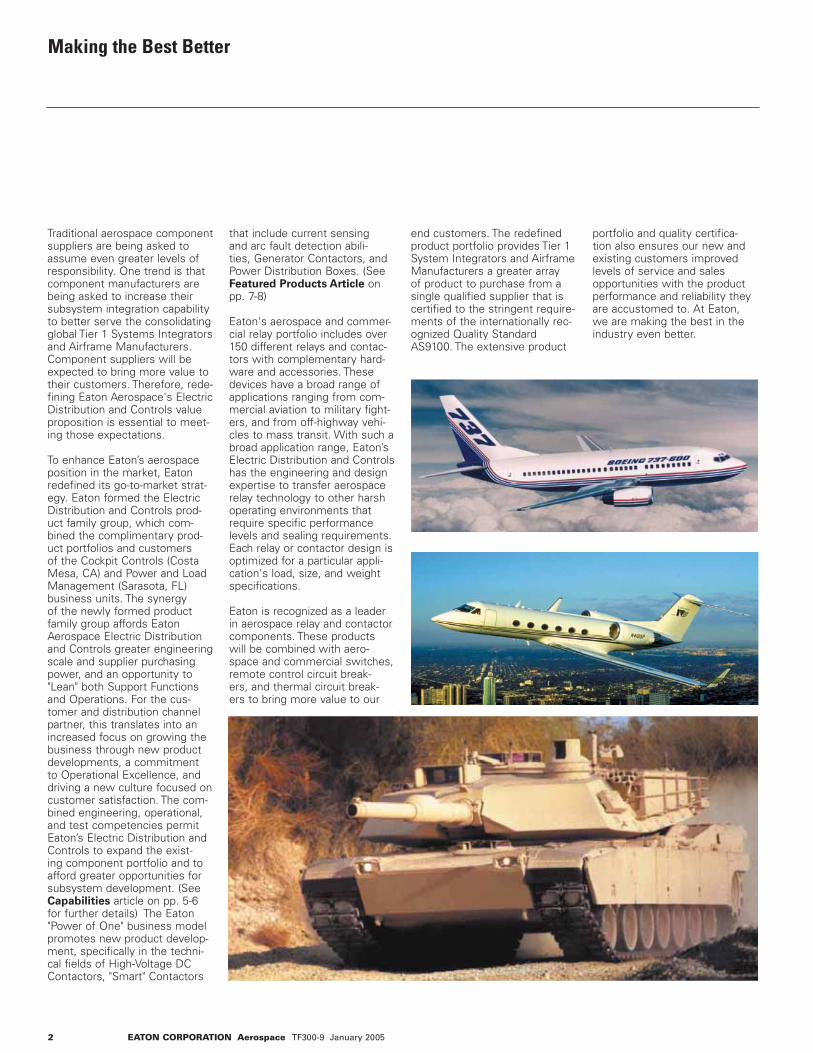
Eaton's aerospace and commer-cial relay portfolio includes over 150 different relays and contac-tors with complementary hard-ware and accessories. These devices have a broad range of applications ranging from com-mercial aviation to military fight-ers, and from off-highway vehi-cles to mass transit. With such a broad application range, Eaton’s Electric Distribution and Controls has the engineering and design expertise to transfer aerospace relay technology to other harsh operating environments that require specific performance levels and sealing requirements. Each relay or contactor design is optimized for a particular appli-cation's load, size, and weight specifications.
Eaton is recognized as a leader in aerospace relay and contactor components. These products will be combined with aero-space and commercial switches, remote control circuit break-ers, and thermal circuit break-ers to bring more value to our
end customers. The redefined product portfolio provides Tier 1 System Integrators and Airframe Manufacturers a greater array of product to purchase from a single qualified supplier that is certified to the stringent require-ments of the internationally rec-ognized Quality Standard AS9100. The extensive product
portfolio and quality certifica-tion also ensures our new and existing customers improved levels of service and sales opportunities with the product performance and reliability they are accustomed to. At Eaton, we are making the best in the industry even better.
2 EATON CORPORATION Aerospace TF300-9 January 2005
EATON CORPORATION Aerospace TF300-9 January 2005 3
Electric Distribution and Controls Relay Catalog
Capabilities and Featured Products
Remote Controlled Circuit Breakers
Power Relays
Hermetically Sealed Power Relays
Lightweight Relays
Generator Contactors
Custom Flat Packs
Table of ContentsFast Information FinderPart Number to Page Index
Capabilities and Featured Products
Eaton CapabilitiesFeatured Products Article(High Volt DC / Next Generation Contactors / Power Distribution Boxes)Notes Remote Controlled Circuit Breakers
Remote Controlled Circuit BreakersRemote Power Controllers Power Relays
Gasket Sealed - 100 to 1000AGasket Sealed - 25 to 400A, Type II and Type III
Hermetically Sealed Power Relays
Hermetically Sealed - 12 to 50AHermetically Sealed - 100 to 400ATerminal Covers Lightweight Relays
Hermetically Sealed Environmentally Sealed
Generator Contactors
Custom Flat Packs
Reference
Military to Eaton Part Number Index
3
4
4
5-8
9
10-21
22-31
32-38
39-42
43-44
45-46
47
Table of Contents
Reference

4 EATON CORPORATION Aerospace TF300-9 January 2005
Fast Information Finder
Find Information Fast
• Have an Eaton part num-
ber and need more infor-
mation? Use the part number to page index on this page to get the exact page of the full product listing.
• Have a Military part
number and need appli-
cable Eaton part num-
ber? Use the Military part number Index in the back of this catalog.
• Need additional informa-
tion not contained in this
catalog? For technical questions, application assistance, or the name of your local authorized dis- tributor, call 1- 800-955- 7354.
Eaton Part No. Page No.
49- 376041H- 266042H- 326046H- 269565H 26GC230/460 8 SM15 41SM50H 32SM100D- 22SM150D- 22SM200D- 22SM400D- 22SM1000D- 22SM100H1 39SM135B2 43SM400H 34SM600BA5 - 100 11SM600BA125 - 200 20SM601BA10 - 60 12
Part Number to Page Index
EATON CORPORATION Aerospace TF300-9 January 2005 5
Capabilities
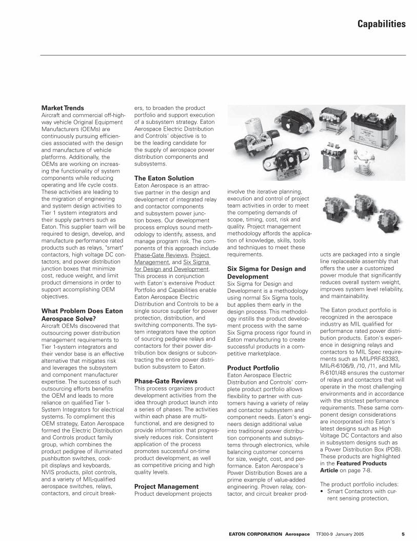
Market TrendsAircraft and commercial off-high-way vehicle Original Equipment Manufacturers (OEMs) are continuously pursuing efficien-cies associated with the design and manufacture of vehicle platforms. Additionally, the OEMs are working on increas-ing the functionality of system components while reducing operating and life cycle costs. These activities are leading to the migration of engineering and system design activities to Tier 1 system integrators and their supply partners such as Eaton. This supplier team will be required to design, develop, and manufacture performance rated products such as relays, "smart" contactors, high voltage DC con-tactors, and power distribution junction boxes that minimize cost, reduce weight, and limit product dimensions in order to support accomplishing OEM objectives.
What Problem Does Eaton
Aerospace Solve?Aircraft OEMs discovered that outsourcing power distribution management requirements to Tier 1-system integrators and their vendor base is an effective alternative that mitigates risk and leverages the subsystem and component manufacturer expertise. The success of such outsourcing efforts benefits the OEM and leads to more reliance on qualified Tier 1-System Integrators for electrical systems. To compliment this OEM strategy, Eaton Aerospace formed the Electric Distribution and Controls product family group, which combines the product pedigree of illuminated pushbutton switches, cock-pit displays and keyboards, NVIS products, pilot controls, and a variety of MIL-qualified aerospace switches, relays, contactors, and circuit break-
ers, to broaden the product portfolio and support execution of a subsystem strategy. Eaton Aerospace Electric Distribution and Controls' objective is to be the leading candidate for the supply of aerospace power distribution components and subsystems.
The Eaton SolutionEaton Aerospace is an attrac-tive partner in the design and development of integrated relay and contactor components and subsystem power junc-tion boxes. Our development process employs sound meth-odology to identify, assess, and manage program risk. The com-ponents of this approach include Phase-Gate Reviews, Project Management, and Six Sigma for Design and Development. This process in conjunction with Eaton's extensive Product Portfolio and Capabilities enable Eaton Aerospace Electric Distribution and Controls to be a single source supplier for power protection, distribution, and switching components. The sys-tem integrators have the option of sourcing pedigree relays and contactors for their power dis-tribution box designs or subcon-tracting the entire power distri-bution subsystem to Eaton.
Phase-Gate ReviewsThis process organizes product development activities from the idea through product launch into a series of phases. The activities within each phase are multi-functional, and are designed to provide information that progres-sively reduces risk. Consistent application of the process promotes successful on-time product development, as well as competitive pricing and high quality levels.
Project ManagementProduct development projects
involve the iterative planning, execution and control of project team activities in order to meet the competing demands of scope, timing, cost, risk and quality. Project management methodology affords the applica-tion of knowledge, skills, tools and techniques to meet these requirements.
Six Sigma for Design and
DevelopmentSix Sigma for Design and Development is a methodology using normal Six Sigma tools, but applies them early in the design process. This methodol-ogy instills the product develop-ment process with the same Six Sigma process rigor found in Eaton manufacturing to create successful products in a com-petitive marketplace.
Product PortfolioEaton Aerospace Electric Distribution and Controls' com-plete product portfolio allows flexibility to partner with cus-tomers having a variety of relay and contactor subsystem and component needs. Eaton's engi-neers design additional value into traditional power distribu-tion components and subsys-tems through electronics, while balancing customer concerns for size, weight, cost, and per-formance. Eaton Aerospace's Power Distribution Boxes are a prime example of value-added engineering. Proven relay, con-tactor, and circuit breaker prod-
ucts are packaged into a single line replaceable assembly that offers the user a customized power module that significantly reduces overall system weight, improves system level reliability, and maintainability.
The Eaton product portfolio is recognized in the aerospace industry as MIL qualified for performance rated power distri-bution products. Eaton's experi-ence in designing relays and contactors to MIL Spec require-ments such as MIL-PRF-83383, MIL-R-6106/9, /10, /11, and MIL-R-6101/48 ensures the customer of relays and contactors that will operate in the most challenging environments and in accordance with the strictest performance requirements. These same com-ponent design considerations are incorporated into Eaton's latest designs such as High Voltage DC Contactors and also in subsystem designs such as a Power Distribution Box (PDB). These products are highlighted in the Featured Products
Article on page 7-8.
The product portfolio includes:• Smart Contactors with cur- rent sensing protection,
6 EATON CORPORATION Aerospace TF300-9 January 2005
Capabilities
Ground Fault Interrupt tech- nology, or Arc Fault Circuit Interrupt technology• 28 Vdc Contactors (50 to1000 amperes)• 270 Vdc Contactors (25 to 350 amperes)• 115/230 Vac 400 Hertz Contactors (30 to 430 amperes)• 750 Vdc Contactors (100 to 600 amperes)• Power Distribution Junction Boxes• A variety of aerospace switches (rocker, toggle, pushbutton and limit).• Pilot Controls including cus- tomized flap controls, landing gear controls, throttle con- trols, trim controls (for mechanical pitch, roll and yaw), and fire emergency controls.• Displays, readable in both direct sunlight and at night, including the popular Series 900 fiber optic displays, as well as displays with surface mount devices and program- mable electronic arrays.• Keyboards that are sunlight and night light readable and suited for virtually any appli- cation, including flight man- agement panels, hand-held data communications panels, shipboard computer control panels, fire system control panels, ground support equip- ment, and radar and teleme try control panels. Eaton Aerospace keyboards also incorporate logic boards, photo sensors, rotary and toggle switches, and annucia- tors, and have features such as micro-processor interfac ing and programmable logic control.• NVIS products such as cock- pit controls, displays and key- boards, and illuminated push button switches that conform to MIL and NVIS specifica- tions and any unique cus- tomer needs.• Illuminated Pushbutton
switches with a multitude of options ranging from sunlight readable, NVIS-compatible, incandescent and LED light- ing to various mounting and termination options for flexi- ble installation and retrofit applications. • Electro-mechanical thermal circuit breakers (0.5 to 300 amperes) - single phase or three phase thermally actuat- ed devices offered in conven- tional design or with integrat- ed Arc Fault Circuit Interrupt technology• Remote Control Circuit Breakers (5 to 125 amperes) - single phase or three-phase devices sold separately or as a subsystem when combined with a necessary indicator control unit (0.5 ampere cir- cuit breaker).• Electromechanical Remote Power Controllers (125 to 200 amperes) - single-phase devices sold separately or as a subsystem when combined with a necessary indicator control unit (0.5 ampere cir- cuit breaker).
Eaton Capabilities• Proven excellence in compo- nent and subsystem design, development, testing, qualifi- cation, and production for both military and commercial aerospace applications.• A manufacturing organization that emphasizes customer satisfaction by focusing on cost, quality, and delivery of the product portfolio.• Altitude / temperature testing chamber simulating altitude to 80,000 feet and tempera- tures from -65°C to 125°C.• Test capabilities of 115/200 Vac 400hz to 3600 amps, 28 Vdc to 10,000 amps, 270/350/475 Vdc to 1,500 amps.• Environmental tests for Sand and Dust, Shock, and Vibration.• Latest CAD/CAM finite ele-
ment analysis and stereolitho- graphic techniques, and PRO- E design.• Model Shop flexibility to respond to design changes and rapid turn around of pro- totypes.
The Eaton DifferenceThere are a number of relay and contactor suppliers in the aero-space market. However, few possess the vertical integration needed to engineer and manu-facture to both MIL Spec and OEM customer specifications to ensure consistency of quality operation in components and subsystems.
Eaton Aerospace affords its cus-tomers the following difference:• Strong brand recognition, cus- tomer loyalty, and demon - strated market presence for over 80 years.• Ability to leverage the compa- ny's size, financial strength, and scope to drive superior results. Eaton Aerospace has the ability to leverage the engineering resources of a multi-billion dollar company.• An extensive product portfo- lio that complements inter grated subsystem design competency.• A flat organizational structure that allows for the optimal blend of best value technical approach and test support within budget and schedule constraints.• Dedicated program managers that understand and commu- nicate the "voice of the cus- tomer".• Design software that pro- motes concurrent engineer- ing and the exchange of cus- tomer data.• Co-located engineering, man- ufacturing, and development resources promote robust product development and product support.
Eaton's unique product portfolio,
its ability to design and manu-facture components and sub-systems, and customer centric strategy mitigates the risk asso-ciated with new aircraft electri-cal power distribution systems. Eaton is an ideal candidate to consider for engineering and manufacturing collaboration on all future commercial, General Aviation, and military programs.

Featured Products
Changing Aerospace Industry
In today's consolidating aero-space industry, Tier 1-System Integrators and Airframe Manufacturers desire more value from their component suppliers. A qualified supplier must not only have an exten-sive product portfolio, but must also display proven subsystem capabilities. These abilities include the capacity to design, manufacture, and test custom-ized power distribution assem-blies that consolidate multiple functions in a single package. Over the past decade, Eaton Aerospace Electric Distribution and Controls (ED&C) acknowl-edged this fact, and has focused its attention on developing these value-add competencies to become a recognized leader in integrated power distribution systems. Specifically, Eaton Aerospace has stayed at the forefront of product / technology development through the devel-opment of the following compo-nents and subassemblies: High-Voltage DC (HVDC) Contactors, Next-Generation Alternating Current (AC) Contactors, and Power Distribution Boxes. High-Voltage DC Contactors
As electrical power systems of 270Vdc and greater become the application standard for high performance aircraft, the
requirements for switching and protection components become increasingly demand-ing. DC switching has always posed greater design challenges versus AC applications. With AC, the current naturally passes through zero each half cycle resulting in quick arc extinction after contact separation.
Conventional 28Vdc switching can also be accomplished using single or double break contact sets. In this case, the inherent arc voltage generated by the anode and cathode of the arc-ing contact sets is capable of opposing and interrupting the current flow. The low voltage device counts little on the arc voltage generated in the actual arc column to drive the current to zero.
Once the system voltage is increased beyond the 48Vdc rating, the interruption scheme becomes more challenging. Although the arc voltage gen-erated by the arc column is generally small compared to the anode and cathode voltages, it will increase as the open con-tact gap widens. The actual arc voltage generated is a function of contact materials, the gas or atmosphere in the contact region, application current, and contact gap. Unfortunately, there is zero crossover to facili-tate interruption, and the design must rely on open gap or arc stretching to match the system voltage. Therefore, with a single or double break contact set, the ability to interrupt 270Vdc quickly becomes size impractical without a more involved inter-ruption scheme.
Eaton Technical Approach
The technology chosen for use within the Eaton line of pat-ented 270Vdc contactors is split-
ting the arc into multiple series arcs under the influence of a constant magnetic field. This is accomplished by driving the arc column into a set of metallic plates housed within an insu-lated arc chute assembly. The multiple plates then provide the significant anode and cathode contribution to the arc voltage required for interruption. The plates also help to cool the arc column, causing the arc to exist at a higher potential and be sta-bilized in a predictable location in the plate. By placing multiple plates within the arc chute, the arc voltage generated during interruption can be increased resulting in less volume required by the arc chute.
With the use of permanent magnets for controlling the arc column, the interruption is consistent even at low levels of application current. This results in extended low-level contact life. This Eaton design allows for smaller device size and the abil-ity to the mount the products in a compact power distribution subsystem.
Benefits of Eaton HVDC
Technology
Eaton Aerospace Electric Distribution and Controls (ED&C) has long been involved in programs addressing require-ments for High Voltage Direct Current (HVDC) applications. Few competitors rival Eaton's knowledge and experience in this technology over the past two decades. The proven air break technology used by the Eaton HVDC contactor line pro-vides the following benefits that competitive HVDC product offer-ings (hermetic) do not provide:
• Eaton was the first contactor manufacturer to complete product design and flight
safety tests for 270Vdc aero space devices.• Hermetic sealing material adds unnecessary device weight. Hermetic sealing material degrades over time compromising the controlled atmosphere within the arc chamber, potentially leading to device failures. Eaton devices have no requirement for a seal.• Hermetic sealed devices are classified by an allowable leakage rate, suggesting they are inherently unstable over time and susceptible to "dor- mant" failures. The Eaton design increases reliability because the splitter plates eliminate single point of fail- ure (inability to interrupt) associated with failed her - metic devices. • Load Polarity - Eaton's devices are bi-directional without restriction. Eaton devices reliably switch small current loads as well as high current loads.• Electrical Life - Eaton end of life characterized by contact voltage drop.• Eaton's design is robust and operates well in harsh envi- ronments as demonstrated by past program performance and application of commer- cialized product.• Eaton's device is a "Qualified" technology per MIL-R-6106 standard for all contactors. • Eaton's device packaging eas- ily tailored for application footprint.• Increased capability to dissi- pate energy for switching inductive loads.• Consistent and controlled switching transients due to ramped build up of arc volt- age upon interruption.• Line Replaceable Unit packag- ing minimizes maintenance time.
EATON CORPORATION Aerospace TF300-9 January 2005 7

8 EATON CORPORATION Aerospace TF300-9 January 2005
The Eaton design does not require a hermetic seal, pro-viding several advantages in application. In military applica-tions, the use of splitter plate technology allows the device to function reliably throughout the life of the airframe while being subjected to harsh combat field environments and flight profiles that involve extreme levels of vibration and shock that can compromise competitors' her-metic seal product designs. The loss of a hermetic seal causes device failure as it relies on the sealed atmosphere within the device to interrupt high voltage. A failure of this nature could cause mission cancellation, mission abort, or even loss of aircraft. If installed in commer-cial aircraft applications, her-metically sealed devices would require periodic maintenance crew checks to prevent the risk of "dormant" failures associated with this design. The Eaton design reduces/eliminates the need for maintenance involve-ment and better supports Air Carrier objectives for mainte-nance-free devices.
Combining ongoing research with current product develop-ment, Eaton Aerospace continu-ally strives to be a premier sup-plier of High-Voltage DC compo-nents and subsystems.
Next Generation Contactors
Eaton Aerospace has extensive experience in the research, design, and development of vari-ous AC Contactor product lines, including "Smart" contactors with integrated current sens-ing and Arc Fault Circuit inter-rupt (AFCI) technology, 28Vdc Lightweight Contactors, and Advanced Generator Contactors.
"Smart" Contactors
Eaton Aerospace is currently developing 175/60 amp pack-ages for galleys, pumps, and primary load distribution. These contactors use the latest tech-nologies, and can include cur-rent sensors for overcurrent protection and/or AFCI sensing. Internal / centralized electron-ics control are also features of these devices. Eaton Aerospace is continually looking for lower weight / size product solutions; a prime example being the 60 amp "Smart" contactor that is currently no bigger than an Eaton 3-phase motor circuit pro-tection device.
28Vdc Lightweight Contactors
Eaton Aerospace is also devel-oping a new 28Vdc, 50-400 Amp contactor family whose focus is on the reduction of weight and cost. Bolt-on designs combine power termi-nations and mechanical mount-ing, and contain captive hard-ware for all mounting fasteners. Both Single Pole Single Throw and Single Pole Double Throw configurations are available with features such as SubD or sealed in-line connectors.
Advanced Generator
Contactors
Based upon Eaton's existing SM15 product line, a new AC Generator contactor line of products is emerging. These contactors have automatic con-trol connector mating and either Three Pole Single Throw or Three Pole Double Throw main contacts. Eaton offers 115 VAC
or 230 VAC (350-800Hz) genera-tor contactors that are bolt-on designs with SubD connectors and rated at either 260 amps or 430 amps. They are currently one of the smallest and lightest AC contactors in the aerospace generator relay market, accom-modate Variable Frequency and double voltage aircraft architec-tures, and are suitable for either stand-alone applications or power distribution boxes.
Power Distribution Boxes
Eaton Aerospace's proven com-ponent expertise and packaging capabilities have allowed Electric Distribution and Controls to become a subsystem supplier in both the commercial jet and military aircraft markets. An example of these competencies is evident in the development of ED&C Power Distribution Boxes. A Power Distribution Box pro-vides the next generation of AC and DC power distribution and protection, whereby convention-al relays, contactors, and circuit protection devices are incorpo-rated into a densely packaged, single line replaceable assembly. Benefits of this type of bundled packaging include weight reduc-tion, reduced maintenance labor time due to the line replaceable nature of these boxes, minimal program risk since commercially off the shelf components are incorporated as often as possi-ble into the design, significantly lower on-aircraft test time since they are tested to the customer
acceptance testing standards prior to shipment, and reduced overall aircraft build time since Power Distribution Boxes sup-port a centralized power distri-bution architecture.
Power Distribution Boxes (PDBs) are typically designed and manufactured for each of the main generators onboard an aircraft in order to provide power to various bus lines and aircraft systems, while other, separate Battery/ External PDBs can provide switching power to a standby power bus and several components such as overhead panels, service lights, and the emergency locator transmitter.
Eaton Aerospace has supplied customers with AC Power Distribution Boxes with fea-tures that direct outputs to high current loads, serve as power feeders to lower current circuit breakers, or act as cur-rent transformers to monitor all outputs. DC Power Distribution Boxes contain such features as Transformer Rectifier Units and Battery Contactors that direct outputs to high current loads, and incorporate Hall Effect sen-sors to monitor outputs. All Power Distribution Boxes can incorporate customized current carrying bus structures, and provide spare electrical power generation capacity to sup-port future electrical systems growth/capacity.
Featured Products
Remote Controlled Circuit Breaker (RCCB)
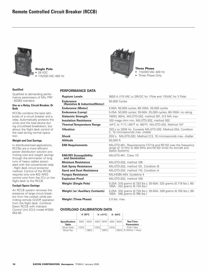
Qualified
Qualified to demanding perfor-mance parameters of MIL- PRF - 83383 standard.
Use as a Relay, Circuit Breaker, Or Both
RCCBs combine the best attri-butes of a circuit breaker and a relay. Automatically protects the wires and the load device dur-ing circuit/load breakdown, but allows the flight deck control of the load during normal opera-tion.
Weight and Cost Savings
In distributed-load applications, RCCBs are a more efficient power distribution solution pro-moting cost and weight savings through the elimination of long runs of heavy cables associ-ated with the conventional relay - flight deck circuit protector method. Control of the RCCB requires only one #22 AWG control wire from the ICU on the flight deck to the RCCB.
Cockpit Space Savings
An RCCB system removes the presence of large circuit break-ers from the cockpit while per-mitting remote On/Off operation from the flight deck. Combine Eaton RCCB with Indicator Control Unit (ICU) model #1500-052-05.
OVERLOAD CALIBRATION DATA
Specification
Table
Must HoldMust Trip
MIN
115%
@ 25°C
MAX
138%
@ +71°C
MIN
115%
MAX
138%
@ -54°C
MIN
115%
MAX
150%
Test Time
Parameters
% for 1 Hour% Within 1 Hour
Single Pole • 28 VDC• 115/200 VAC 400 Hz
Three Phase • 115/200 VAC 400 Hz• Three Phase Only
Rupture Levels 3600 A (115 VAC or 28VDC for 1Pole and 115VAC for 3 Pole) Endurance 50,000 Cycles (Resistive & Inductive(Motor) Endurance (Motor) 5-50A: 50,000 cycles; 60-100A: 25,000 cycles Endurance (Lamp) 5-25A: 50,000 cycles; 35-50A: 25,000 cycles; 60-100A: no rating Dielectric Strength 1500V, 60Hz, MIL-STD-202, method 301, 0.5 MA max Insulation Resistance 100 mega ohm min, MIL-STD-202, method 302 Thermal Temperature Range -54°C to 71°C (-65°F to 160°F). MIL-STD-202, Method 107 Vibration 10G's to 2000 Hz. Exceeds MIL-STD-202, Method 204, Condition C, 10 microseconds max. chatter Shock 25G's. MIL-STD-202, Method 213, 10 microseconds max. chatter Altitude 50,000 ft. EMI Requirements MIL-STD-461, Requirements CS114 and RE102 over the frequency range of 14 KHz to 400 MHz and RE102 limits for Aircraft and Space Systems. EMI/RFI Susceptibility MIL-STD-461, Class 1D and Generation Moisture Resistance MIL-STD-202, method 106 Salt Spray Resistance MIL-STD-202, method 101, Condition B Sand and Dust Resistance MIL-STD-202, method 110, Condition A Fungus Resistance MIL-HDBK-454, Guideline 4 Explosion Proof MIL-STD-202, method 109 Weight (Single Pole) 5-25A: 318 grams (0.703 lbs.); 35-50A: 325 grams (0.719 lbs.); 60- 100A: 332 grams (0.734 lbs.) Weight (w/ Auxiliary Contacts) 5-25A: 332 grams (0.734 lbs.); 35-50A: 339 grams (0.750 lbs.); 60- 100A: 346 grams (0.766 lbs.)
Weight (Three Phase) 2.0 lbs. max.
PERFORMANCE DATA
10 EATON CORPORATION Aerospace TF300-0 January 2005
EATON CORPORATION Aerospace TF300-9 January 2005 11
Remote Controlled Circuit Breaker (RCCB)
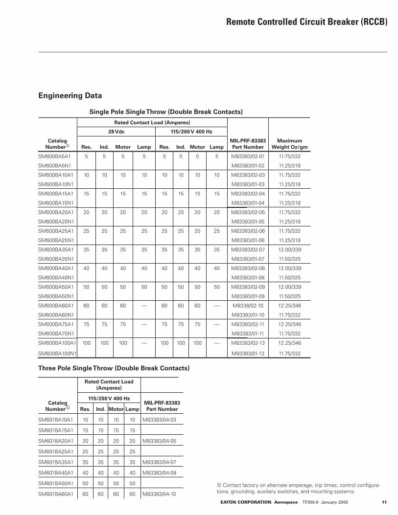
Engineering Data
Single Pole Single Throw (Double Break Contacts)
Three Pole Single Throw (Double Break Contacts)
Catalog
Number1
Rated Contact Load (Amperes)
MIL-PRF-83383
Part Number
Maximum
Weight Oz/gm
28 Vdc 115/200 V 400 Hz
Res. Ind. Motor Lamp Res. Ind. Motor Lamp
SM600BA5A1 5 5 5 5 5 5 5 5 M83383/02-01 11.75/332
SM600BA5N1
10 10 10 10 10 10 10 10
M83383/01-02 11.25/318
SM600BA10A1 M83383/02-03 11.75/332
SM600BA10N1
15 15 15 15 15 15 15 15
M83383/01-03 11.25/318
SM600BA15A1 M83383/02-04 11.75/332
SM600BA15N1
20 20 20 20 20 20 20 20
M83383/01-04 11.25/318
SM600BA20A1 M83383/02-05 11.75/332
SM600BA20N1
25 25 25 25 25 25 25 25
M83383/01-05 11.25/318
SM600BA25A1 M83383/02-06 11.75/332
SM600BA25N1
35 35 35 35 35 35 35 35
M83383/01-06 11.25/318
SM600BA35A1 M83383/02-07 12.00/339
SM600BA35N1
40 40 40 40 40 40 40 40
M83383/01-07 11.50/325
SM600BA40A1 M83383/02-08 12.00/339
SM600BA40N1
50 50 50 50 50 50 50 50
M83383/01-08 11.50/325
SM600BA50A1 M83383/02-09 12.00/339
SM600BA50N1
60 60 60 — 60 60 60 —
M83383/01-09 11.50/325
SM600BA60A1 M8338/02-10 12.25/346
SM600BA60N1
75 75 75 — 75 75 75 —
M83383/01-10 11.75/332
SM600BA75A1 M83383/02-11 12.25/346
SM600BA75N1
100 100 100 — 100 100 100 —
M83383/01-11 11.75/332
SM600BA100A1 M83383/02-13 12.25/346
SM600BA100N1 M83383/01-13 11.75/332
Catalog
Number1
Rated Contact Load
(Amperes)
115/200 V 400 HzMIL-PRF-83383
Part NumberRes. Ind. Motor Lamp
SM601BA10A1 10 10 10 10 M83383/04-03
SM601BA15A1 15 15 15 15
SM601BA20A1 20 20 20 20 M83383/04-05
SM601BA25A1 25 25 25 25
SM601BA35A1 35 35 35 35 M83383/04-07
SM601BA40A1 40 40 40 40 M83383/04-08
SM601BA50A1 50 50 50 50
SM601BA60A1 60 60 60 60 M83383/04-10
1 Contact factory on alternate amperage, trip times, control confi gura-tions, grounding, auxiliary switches, and mounting systems.

ORDERING INFORMATION
AMPERE
RATING
5
7.5
10
15
20
25
35
40
50
60
75
80
100
MS P/N
M83383/01-01
M83383/01-03M83383/01-04M83383/01-05M83383/01-06M83383/01-07M83383/01-08M83383/01-09M83383/01-10M83383/01-11
M83383/01-13
Single Pole Single Throw (Double Break Contacts) Three Pole Single Throw (Double
Break Contacts)
Standard w/ Auxiliary Contacts w/ Auxiliary Contacts
*
*
*
*
EATON P/N
SM600BA5N1**
SM600BA10N1SM600BA15N1SM600BA20N1SM600BA25N1SM600BA35N1SM600BA40N1SM600BA50N1SM600BA60N1SM600BA75N1
**SM600BA100N1
MS P/N
M83383/02-01
M83383/02-03M83383/02-04M83383/02-05M83383/02-06M83383/02-07M83383/02-08M83383/02-09M83383/02-10M83383/02-11
M83383/02-13
EATON P/N
SM600BA5A1**
SM600BA10A1SM600BA15A1SM600BA20A1SM600BA25A1SM600BA35A1SM600BA40A1SM600BA50A1SM600BA60A1SM600BA75A1
**SM600BA100A1
MS P/N
M83383/04-03
M83383/04-05
M83383/04-07M83383/04-08
M83383/04-10
EATON P/N
****
SM601BA10A1SM601BA15A1SM601BA20A1SM601BA25A1SM601BA35A1SM601BA40A1SM601BA50A1SM601BA60A1
All Ampere Ratings equal to Rated Contact Loads (Resistive, Inductive, Motor, and Lamp) except as noted. * No Lamp Load Rating ** Contact Factory Note: Contact factory on alternate amperage, trip times, control configuations, grounding, auxilary switches, mounting systems, etc.
Remote Controlled Circuit Breaker (RCCB)
OVERLOAD CALIBRATION DATA
Ratings
All
Percent
Rated Current
115%138%115%150%
Ambient Temperature
Degrees C. ± 5°
25°C & 71°C
-54°C
Tripping Time
No Trip1 Hour Max.*
No Trip1 Hour Max.*
* Must trip in one hour.
SINGLE POLE
OVERLOAD CALIBRATION DATA
Ratings
All
Percent
Rated Current
115%138%115%150%
Ambient Temperature
Degrees C. ± 5°
25°C & 71°C
-54°C
Tripping Time
No Trip1 Hour Max.*
No Trip1 Hour Max.*
* Must trip in one hour.
TRIPLE POLE
AMPERE
RATING
AMPERES1015202535405060
MINSECONDS
1213141516161313
200% Trip Times
-54°C to +71°C
MAXSECONDS
8080808080808080
400% Trip Times
-54°C to +71°C
MINSECONDS
2.81.72.92.62.82.62.92.4
MAXSECONDS
11109.61011101016
1000% Trip Times
-54°C to +71°C
MINSECONDS
0.420.350.40.4
0.350.360.4
0.26
MAXSECONDS
1.31.21.151.31.31.31.251.8
TRIP CURVE
Contact business unit for trip curve.
AMPERE
RATING
AMPERES5
7.510152025354050607580100
MINSECONDS
7111213141516161313131417
200% Trip Times
-54°C to +71°C
MAXSECONDS
40404245465055555560606063
400% Trip Times
-54°C to +71°C
MIN SECONDS
1.22.42.81.72.92.62.82.92.92.62.52.73.5
MAXSECONDS
6.46.88.58.37.68.78.39.2101313
12.513
1000% Trip Times
-54°C to +71°C
MINSECONDS
0.30.330.420.350.40.40.350.360.40.260.260.30.38
MAXSECONDS
1.21.11.051.21.151.31.31.31.251.81.82
1.9
OVERLOAD CALIBRATION DATA — SINGLE POLE OVERLOAD CALIBRATION DATA — THREE POLE
12 EATON CORPORATION Aerospace TF300-0 January 2005
Remote Controlled Circuit Breaker (RCCB)
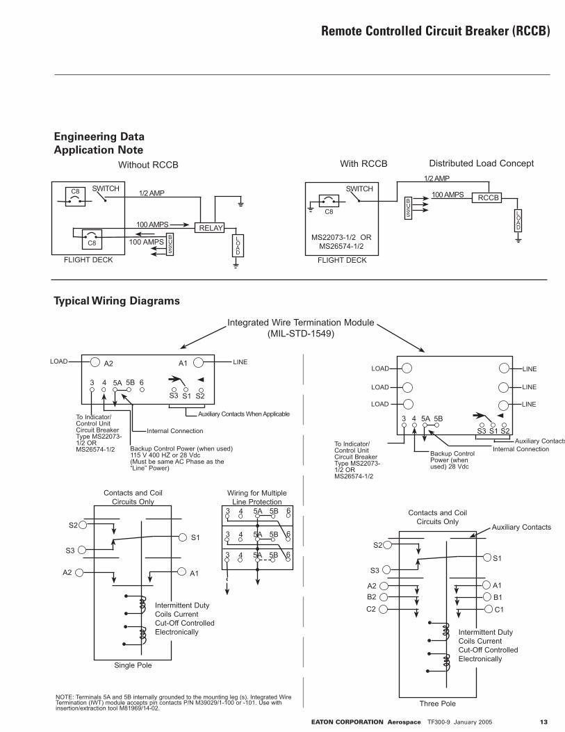
Engineering Data
Application Note
C8
FLIGHT DECK
SWITCH
MS22073-1/2 ORMS26574-1/2
BUSS L
OAD
1/2 AMP
100 AMPS RCCB
With RCCB Distributed Load Concept
Typical Wiring Diagrams
NOTE: Terminals 5A and 5B internally grounded to the mounting leg (s). Integrated Wire Termination (IWT) module accepts pin contacts P/N M39029/1-100 or -101. Use with insertion/extraction tool M81969/14-02.
Contacts and Coil Circuits Only
S2
S3
Three Pole
A2
Auxiliary Contacts
S1
Intermittent Duty Coils Current Cut-Off Controlled Electronically
B2C2
A1B1
C1
Contacts and Coil Circuits Only
S2
S3
A2
S1
A1
Single Pole
Intermittent Duty Coils Current Cut-Off Controlled Electronically
Without RCCB
C8
C8BUSS
FLIGHT DECK
100 AMPS
RELAY
SWITCH 1/2 AMP
100 AMPS
LOAD
Integrated Wire Termination Module (MIL-STD-1549)
5A 5B
S3 S1 S2
A1A2
To Indicator/Control Unit Circuit Breaker Type MS22073-1/2 OR MS26574-1/2 Backup Control Power (when used)
115 V 400 HZ or 28 Vdc(Must be same AC Phase as the “Line” Power)
Internal Connection
Auxiliary Contacts When Applicable
LINELOAD
3 4 6
LOAD
LOAD
LOAD
LINE
LINE
LINE
To Indicator/Control Unit Circuit Breaker Type MS22073-1/2 OR MS26574-1/2
5A 5B
S3 S1 S2
Backup Control Power (when used) 28 Vdc
Internal Connection Auxiliary Contacts
3 4
EATON CORPORATION Aerospace TF300-9 January 2005 13
Wiring for Multiple Line Protection
3 4 5A 65B
3 4 5A 65B
3 4 5A 65B

Remote Controlled Circuit Breaker (RCCB) — 1 Pole and 3 Pole
Engineering Data
Approximate Dimensions - 1 Pole
Options
• Special application auxiliary switches• Unique grounding• Power sources• Other current ratings• Control via systems other than I/CU• Low level auxiliary con- tacts available• Data Bus/Interface capabil- ity available• Electronically held coil• Moisture resistant sealing
Three Pole
Typical Placement of Rating on Top Plane
LOA
D A
2
LIN
E A
1
50
.172/4.37 DIA.2 MTG. HOLESR. 20
5.08
.688/17.48
2.94074.68
3.25082.55
Main Contact Position Indicator
Red: Closed; Green: Open
Mtg. Flanges Mate As Shown
1.53038.86
2.25057.15 .350
8.89 .071.778
.500 - .61012.70 - 15.24
.1804.57
3.4286.87
Name Plate
.0842.13
4.26108.20
.0561.42
.4210.67
1.20030.48
LO
AD
A2
LO
AD
B2
LOA
D C
2
LIN
E A
1LIN
E B
1L
INE
C1
50
2.52664.16
2.94074.68
3.25082.55
2.52664.16
Main Contact Position Indicator
Red: Closed; Green: Open
2.2857.91
1.5038.86
.3508.89
.071.78
.051.27
4.26108.20
3.4387.12
.1303.30
.7719.56
2.0351.56
3.2983.57
3.6993.73
Location of NamePlate
14 EATON CORPORATION Aerospace TF300-0 January 2005
Coil Operate Current/Set And Trip Time RCCB
Circuits
1 Pole
3 Pole
Nominal
System
Voltage
28 Vdc(18 Volts MIN.)
115 Vac400 Hz (104 V.
MIN.28 Vdc
(18 Volts MIN.)115 Vac
400 Hz (104 V. MIN.)
I/CU Set
Current
@ Nom
Voltage
(Mulliamp)
2
2
2
2
Set Coil
Current
@ Nom
Voltage
Pulse
3.0 AMP MAX
10 AMPMAX
7.0 AMPMAX
13.0 AMPMAX
Nominal
Voltage &
Room Temp.
20 Millisec
15 Millisec
20 Millisec
15 Millisec
MAX. Set TimeMost Adverse
Condition - MIN.
Voltage 71°C.
Ambient
35 Millisec
30 Millisec
35 Millisec
30 Millisec
*I/CU. Trip Current Nominal71°C &
Nominal
Voltage
1.4 AMP
6.8 AMP**
1.5 AMP
4.3 AMP**
-54°C &
Nominal
Voltage
1.9 AMP
6.3 AMP**
2.0 AMP
3.3 AMP**
Room Temp.
Nominal
Voltage
1.6 AMP
8.6 AMP**
1.7 AMP
4.5 AMP**
71°C &
Nominal
Voltage
0.9 AMP***
6.1 AMP**
0.9 AMP***
4.0 AMP**
-54°C &
Nominal
Voltage
2.1 AMP
7.0 AMP**
2.2 AMP
3.1 AMP**
MAX.
Standby
Current
Milliamp
10
10
10
10
* MAX. I/CU. Line Impedance 7.5 Current Decreases w/Time so that I2t** Average Half-Wave Rectified DC Current ***Absolute Min. Value from -54° to +71°C
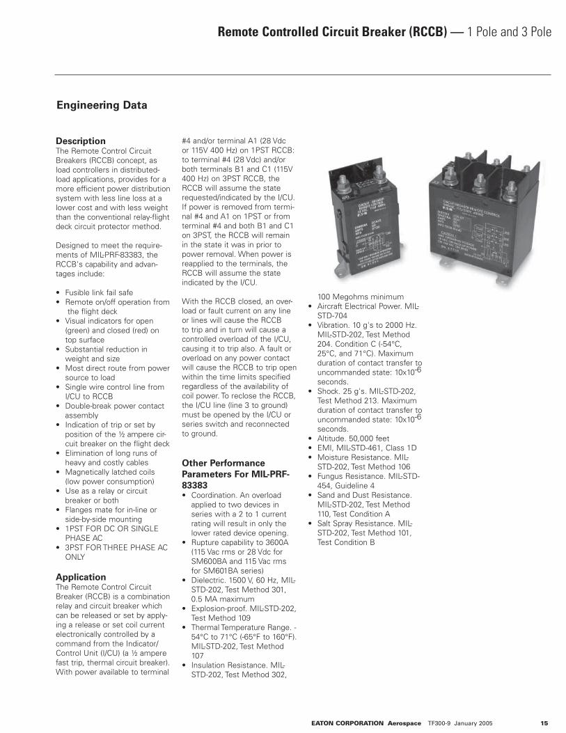
DescriptionThe Remote Control Circuit Breakers (RCCB) concept, as load controllers in distributed-load applications, provides for a more efficient power distribution system with less line loss at a lower cost and with less weight than the conventional relay-flight deck circuit protector method.
Designed to meet the require-ments of MIL-PRF-83383, the RCCB's capability and advan-tages include:
• Fusible link fail safe• Remote on/off operation from the flight deck• Visual indicators for open (green) and closed (red) on top surface• Substantial reduction in weight and size• Most direct route from power source to load• Single wire control line from I/CU to RCCB• Double-break power contact assembly• Indication of trip or set by position of the ½ ampere cir- cuit breaker on the flight deck• Elimination of long runs of heavy and costly cables• Magnetically latched coils (low power consumption)• Use as a relay or circuit breaker or both• Flanges mate for in-line or side-by-side mounting• 1PST FOR DC OR SINGLE PHASE AC• 3PST FOR THREE PHASE AC ONLY
ApplicationThe Remote Control Circuit Breaker (RCCB) is a combination relay and circuit breaker which can be released or set by apply-ing a release or set coil current electronically controlled by a command from the Indicator/Control Unit (I/CU) (a ½ ampere fast trip, thermal circuit breaker).With power available to terminal
#4 and/or terminal A1 (28 Vdc or 115V 400 Hz) on 1PST RCCB: to terminal #4 (28 Vdc) and/or both terminals B1 and C1 (115V 400 Hz) on 3PST RCCB, the RCCB will assume the state requested/indicated by the I/CU. If power is removed from termi-nal #4 and A1 on 1PST or from terminal #4 and both B1 and C1 on 3PST, the RCCB will remain in the state it was in prior to power removal. When power is reapplied to the terminals, the RCCB will assume the state indicated by the I/CU.
With the RCCB closed, an over-load or fault current on any line or lines will cause the RCCB to trip and in turn will cause a controlled overload of the I/CU, causing it to trip also. A fault or overload on any power contact will cause the RCCB to trip open within the time limits specified regardless of the availability of coil power. To reclose the RCCB, the I/CU line (line 3 to ground) must be opened by the I/CU or series switch and reconnected to ground.
Other Performance
Parameters For MIL-PRF-
83383• Coordination. An overload applied to two devices in series with a 2 to 1 current rating will result in only the lower rated device opening.• Rupture capability to 3600A (115 Vac rms or 28 Vdc for SM600BA and 115 Vac rms for SM601BA series)• Dielectric. 1500 V, 60 Hz, MIL- STD-202, Test Method 301, 0.5 MA maximum• Explosion-proof. MIL-STD-202, Test Method 109• Thermal Temperature Range. - 54°C to 71°C (-65°F to 160°F). MIL-STD-202, Test Method 107• Insulation Resistance. MIL- STD-202, Test Method 302,
100 Megohms minimum• Aircraft Electrical Power. MIL- STD-704• Vibration. 10 g's to 2000 Hz. MIL-STD-202, Test Method 204. Condition C (-54°C, 25°C, and 71°C). Maximum duration of contact transfer to uncommanded state: 10x10-6 seconds.• Shock. 25 g's. MIL-STD-202, Test Method 213. Maximum duration of contact transfer to uncommanded state: 10x10-6 seconds. • Altitude. 50,000 feet• EMI, MIL-STD-461, Class 1D• Moisture Resistance. MIL- STD-202, Test Method 106• Fungus Resistance. MIL-STD- 454, Guideline 4• Sand and Dust Resistance. MIL-STD-202, Test Method 110, Test Condition A• Salt Spray Resistance. MIL- STD-202, Test Method 101, Test Condition B
Remote Controlled Circuit Breaker (RCCB) — 1 Pole and 3 Pole
Engineering Data
EATON CORPORATION Aerospace TF300-9 January 2005 15
Remote Controlled Circuit Breaker (RCCB)
Introduction
Part of the weight of the mod-ern jet aircraft comes from the electrical wires and power control systems needed to dis-tribute the electrical energy. As these aircraft increase their pas-senger carrying capability, the electrical power management system becomes more complex and could become heavier. Wire runs of more than 300 feet from the flight deck circuit breakers to the load become common.
Utilization of Eaton's Remote Controlled Circuit Breakers (RCCB) close to the load or power source will eliminate much of these long, heavy, and expensive wire/cable. Control of the RCCB requires only one #22 AWG control wire from the flight deck to the RCCB.
Weight reduction, directly from wire use and indirectly from (generator) line heat loss, and installation and maintenance cost reductions becomes sig-nificant.
The RCCB combines the best attributes of a circuit breaker and a relay. The RCCB automati-cally protects the wires and the load device during circuit/load breakdown, but allows flight deck control of the load during normal operation.
Operation
The RCCB is basically a relay and a circuit breaker and allows the utilization of each identity singularly or in combination, depending upon the application. All of the RCCB's capabilities apply in either application.
It can be employed as a relay located adjacent to its load and remotely operated much like relays are today through control wiring and a switching device in the flight deck.
It can also be utilized as a
circuit breaker and mounted adjacent to the load, the power source, or even the flight deck.
Single Pole RCCB
Motor Operation
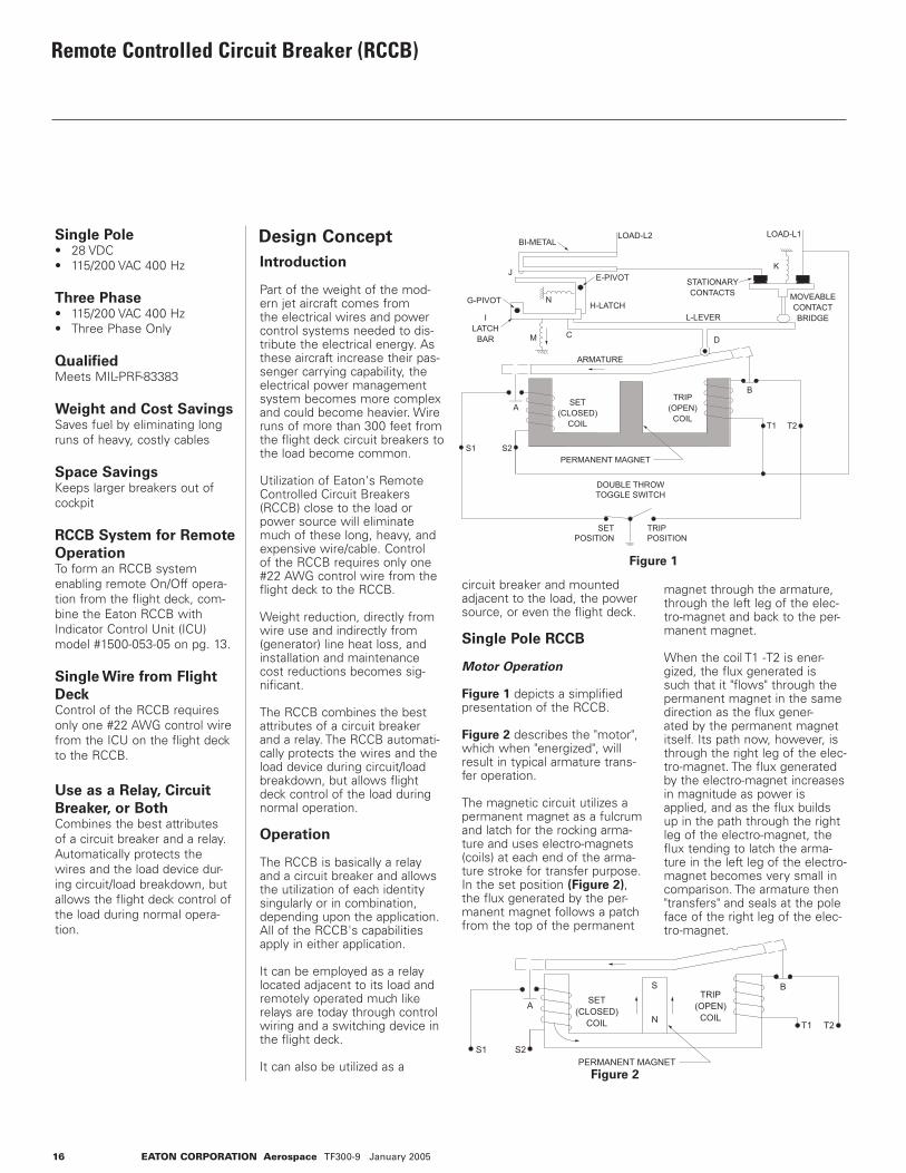
Figure 1 depicts a simplified presentation of the RCCB.
Figure 2 describes the "motor", which when "energized", will result in typical armature trans-fer operation.
The magnetic circuit utilizes a permanent magnet as a fulcrum and latch for the rocking arma-ture and uses electro-magnets (coils) at each end of the arma-ture stroke for transfer purpose. In the set position (Figure 2), the flux generated by the per-manent magnet follows a patch from the top of the permanent
magnet through the armature, through the left leg of the elec-tro-magnet and back to the per-manent magnet.
When the coil T1 -T2 is ener-gized, the flux generated is such that it "flows" through the permanent magnet in the same direction as the flux gener-ated by the permanent magnet itself. Its path now, however, is through the right leg of the elec-tro-magnet. The flux generated by the electro-magnet increases in magnitude as power is applied, and as the flux builds up in the path through the right leg of the electro-magnet, the flux tending to latch the arma-ture in the left leg of the electro-magnet becomes very small in comparison. The armature then "transfers" and seals at the pole face of the right leg of the elec-tro-magnet.
Single Pole• 28 VDC• 115/200 VAC 400 Hz
Three Phase• 115/200 VAC 400 Hz• Three Phase Only
QualifiedMeets MIL-PRF-83383
Weight and Cost SavingsSaves fuel by eliminating long runs of heavy, costly cables
Space SavingsKeeps larger breakers out of cockpit
RCCB System for Remote
OperationTo form an RCCB system enabling remote On/Off opera-tion from the flight deck, com-bine the Eaton RCCB with Indicator Control Unit (ICU) model #1500-053-05 on pg. 13.
Single Wire from Flight
DeckControl of the RCCB requires only one #22 AWG control wire from the ICU on the flight deck to the RCCB.
Use as a Relay, Circuit
Breaker, or BothCombines the best attributes of a circuit breaker and a relay. Automatically protects the wires and the load device dur-ing circuit/load breakdown, but allows the flight deck control of the load during normal opera-tion.
Design Concept BI-METAL
E-PIVOT
H-LATCHG-PIVOT
LOAD-L2 LOAD-L1
K
B
D
A
S1 S2
M
N
J
T2T1
L-LEVER
ARMATURE
PERMANENT MAGNET
DOUBLE THROWTOGGLE SWITCH
SETPOSITION
TRIPPOSITION
STATIONARYCONTACTS
ILATCH
BAR
MOVEABLE CONTACT BRIDGE
TRIP(OPEN)
COIL
SET(CLOSED)
COIL
C
Figure 1
BS
N
A
S1 S2
T2T1
PERMANENT MAGNET
TRIP(OPEN)
COIL
SET(CLOSED)
COIL
Figure 2
16 EATON CORPORATION Aerospace TF300-9 January 2005

Remote Controlled Circuit Breaker (RCCB) — Design Concept
The cutthroat contact B in series with coil T1 -T2 is opened by mechanical actuation due to the armature movement. In Figure 2, a "dotted extension" of the armature represents the mechanical actuator of the cutthroat contacts. In actual design, this is accomplished more conveniently through only one armature extension and an appropriate actuator which drives both contacts B and A.
The opening of contact B occurs in the last several thousandths of an inch travel of the armature movement. After coil opening, the armature movement contin-ues (until it seats i.e. seals), due in some degree to the inertia of the armature, but mostly due to the magneto-motive force of the permanent magnet in conjunc-tion with the decreasing air gap at the right pole face.
The device now is again in a stable position, but the armature has transferred and the follow-ing conditions exist:
Contact A is closed and contact B is open, and the armature is sealed and latched at the right leg of the electro-magnet. To transfer the armature to its original position, energizing the coil S1-S 2 allows the process described above to occur in the opposite direction.
There are a number of advan-tages to this design approach of the "motor."
1. The coils open upon transfer of the armature; hence, the actual "on time" or duty cycle approximately equals the operate time of the relay. Accordingly, the coil can be driven hard without fear of burnout. The "hot coil" with the low timer constant results, in turn, in fast oper- ate times.2. Using intermittent duty coils (smaller coils with less cop- per) results in less weight and smaller sizes. 3. Power is conserved. This is important for two reasons.
If a relay is to use power, it must be available. In some of the present day and future vehicles, power remains an expensive commodity, and elimination of coil power drawing (10-35 watts) in power devices can add up especially when vehicles sophistication requires use of a significant number of these devices. Also, it must be remembered that power uti- lized by relay coils generate heat which must be dissipat- ed. The necessary elimination of this heat, in turn, requires the use of additional energy from the main power source. 4. As indicated, the cutthroat contacts are opened by the armature mechanically during the last several thousandths of an inch travel of armature movement. Note: In actual RCCB, the cutthroat contacts function is replaced by elec- tronic control of coil on time.
RCCB Operation As A Relay
To examine the RCCB operation as a relay, refer to Figure 3 and 4. The device is shown in the set position in Figure 3 and in the tripped position in Figure 4. The circuit path is from L2, through the bimetal to one of the stationary contacts. L1 is connected directly to the other stationary contact.
The movable bridge closes the circuit by bridging between the two stationary contacts.
As can be seen, movement of the armature about its fulcrum will determine the position of the contacts. When coil S1-S 2 has been energized such that the armature seals on the left-hand pole face (Figure 3), the mechanical linkage system closes the contacts. Conversely, when coil T1-T 2 has been ener-gized, such that the armature seals on the right-hand pole face (Figure 4), the relay contacts will open due to the spring forces exerted by compression spring K.
Note: there is an "upward force" directed on the lever L through the linkage tying into the armature at point D. During operation as a relay, point C (interface between lever L and latch bar I) is "fixed" in place, and the lever L actually rotates about point C when moving the contact structure from the opening to the closed, and from the closed to the open position.
BI-METAL
E-PIVOT
H-LATCHG-PIVOT
LOAD-L2 LOAD-L1
K
B
D
S
N
AS2 U1
S1 U2
M
N
J
T2T1V1
V1
L-LEVER
ARMATURE
PERMANENT MAGNET
STATIONARYCONTACTS
ILATCH
BAR
BUCKINGCOIL
MOVEABLE CONTACT BRIDGE
TRIP(OPEN)
COIL
BUCKINGCOIL
SET(CLOSED)
COIL
C
Figure 3
BI-METAL
E-PIVOT
H-LATCHG-PIVOT
LOAD-L2
LOAD-L1
K
B
D
S
N
A
S2 U1
S1 U2
M
C
N
J
T2T1
V1
V1
L-LEVER
ARMATURE
PERMANENT MAGNET
STATIONARYCONTACTS
ILATCH
BAR
BUCKINGCOIL
MOVEABLE CONTACT BRIDGE
TRIP(OPEN)
COIL
BUCKINGCOIL
SET(CLOSED)
COIL
Figure 4
E-PIVOT
H-LATCHG-PIVOT
BI-METAL
LOAD-L2
LINE-L1
B
K
D
S
N
A
S1 S2
N
M
ARMATURE
J
T2T1
PERMANENT MAGNET
STATIONARYCONTACTS
L-LEVERI
LATCHBAR
MOVEABLE CONTACT BRIDGE
TRIP(OPEN)
COIL
SET(CLOSED)
COIL
Figure 5
EATON CORPORATION Aerospace TF300-9 January 2005 17
18 EATON CORPORATION Aerospace TF300-9 January 2005
Remote Controlled Circuit Breaker (RCCB) — Design Concept
Note that the coil U1-U2 is con-nected in parallel with T1-T2. It is wound on the left-hand core of the electro-magnet such that when energized along with T1-T2, the force it generates will be in a direction opposing the latch-ing force generated in that core by the permanent magnet.
The utilization of a permanent magnet and intermittent duty coils, in conjunction with cut-throat contacts, allows a consid-erable reduction in copper and iron from that normally required in electro-magnets for continu-ous duty operation.
RCCB Operation as a
Circuit Breaker
To examine the operation of the device as a breaker, refer to Figures 3, 4, and 5.
In Figure 3, the device is shown in the closed contact position (presumably) carrying rated cur-rent. Should an overload occur, currents greater than rated cur-rents now "flow" through the device "entering" through L2, passing through the bimetal, through the connection of the bimetal to one stationary contact, through the bridging moveable contact structure, to the other stationary contact, and "out" through L1.
Depending upon the size of the overload, the bimetal will begin to deflect as shown in Figure
5 until the actuating end of the bimetal engages latch H at point J.
Motion and force due to the deflection of the bimetal moves latch H such that it rotates in a counter-clockwise direction around its pivot point E.
When latch H has moved an adequate distance, the upward force of lever L, applied at point
C to latch bar I, will rotate latch bar I counter-clockwise around its pivot point G. This allows the main lever L to rotate clockwise around point D (where it is engaged with the armature) due to the "contact return" spring (compression spring) force K acting upon the moveable con-tact bridge.
Note that when this overload occurs, the armature is not transferred to the "off" (tripped) position, but instead remains in the latched position normally associated with the "on" (set) position of the device.
To "reset" the device after the fault or overload clears could be readily accomplished by energiz-ing the "trip" coil (T1-T2) through a toggle or push-button switch (see Figure 1) located in the flight deck. The armature would then transfer and seal on the right-hand core of the electro-magnet, which is the "open" position shown in Figure 4. At that time, springs M and N (ten-sion springs) would reposition latch bar I and latch H to the position shown in Figure 4, pro-viding that the bimetal has now cooled sufficiently and returned to its original position as shown in Figure 4. At this stage, the RCCB is still in an "open posi-tion" i.e. (the contacts are open), but as outlined above, the fault or overload has been cleared through action and operation of the device through bimetal-lic activity, i.e. "Circuit Breaker" operation.
To re-close the contacts, it is now only necessary to energize coils S1-S2 and re-establish a mechanism position similar to that shown in Figure 3. If the fault of overload condition is still in existence, the device would again trip through bimetallic activity as just described.
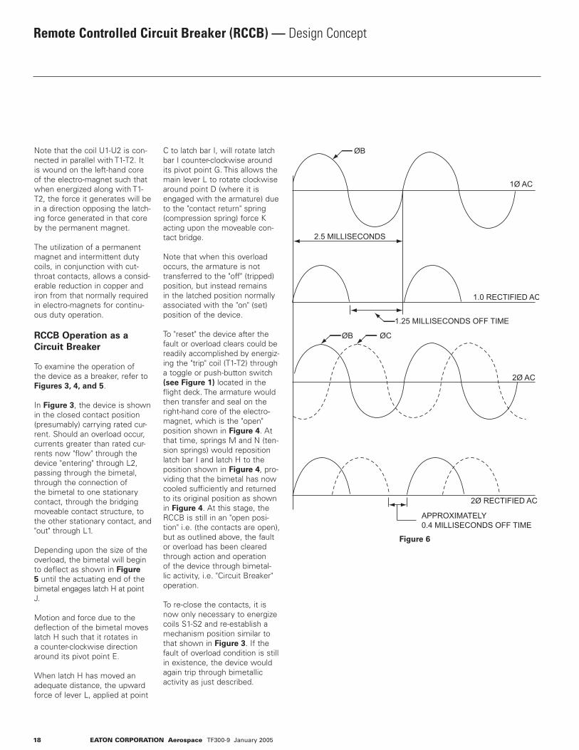
2.5 MILLISECONDS
1.0 RECTIFIED AC
2Ø RECTIFIED AC
APPROXIMATELY0.4 MILLISECONDS OFF TIME
1Ø AC
2Ø AC
ØB
ØB
ØC
1.25 MILLISECONDS OFF TIME
Figure 6
EATON CORPORATION Aerospace TF300-9 January 2005 19
Three Pole RCCB
The design principles employed in the 3-pole RCCB have fol-lowed many of the same paths utilized in the 1-pole RCCB. Differences other than the obvious, such as size, weight, shape, etc., are explained below.
Motor Operation
The principles of motor opera-tion and construction of the three pole devices are similar to those employed in the single pole RCCB. In the 3-pole device, the AC operating power is drawn from two of the three
phases. The "off" time between current pulses during coil ener-gization is approximately 0.4 milliseconds. In comparison, the "off" time for single-phase power is approximately 1.25 millisec-onds. See Figure 6.
The timing circuit establishes a coil "on" time longer than the actual transfer time of the arma-ture. The operation of the 3-pole RCCB is identical to the 1-pole.
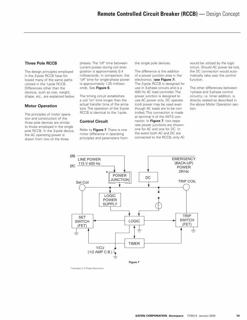
Control Circuit
Refer to Figure 7. There is one minor difference in operating principles and parameters from
the single pole devices.
The difference is the addition of a power junction area in the electronics. (see Figure 7).The 3-pole RCCB is designed for use in 3-phase circuits and is a 400 Hz AC load controller. The power junction is designed to use AC power only. DC operate (coil) power may be used even though AC loads are to be con-trolled. This connection is made at terminal 4 of the IWTS con-nector. In Figure 7, two sepa-rate power junctions are shown: one for AC and one for DC. In the event both AC and DC are connected to the RCCB, only AC
would be utilized by the logic circuit. Should AC power be lost, the DC connection would auto-matically take over the control function.
The other differences between 1-phase and 3-phase control circuitry, i.e. timer addition, is directly related as described in the above Motor Operation sec-tion.
LINE POWER115 V 400 Hz
1/CU(1/2 AMP C.B.)
SETSWITCH
(FET)
EMERGENCY(BACK-UP)
POWER28Vdc
TRIPSWITCH
(FET)
LOGICPOWERSUPPLY
POWERJUNCTION TRIP COIL
LOGIC
TIMER
DC
ØB
ØC
Set Coil
Figure 7
*Indicates In 3 Phase Electronics
*
Remote Controlled Circuit Breaker (RCCB) — Design Concept

20 EATON CORPORATION Aerospace TF300-9 January 2005
Remote Power Controllers — With Electronic Current Sensing
OVERLOAD DATA
% Rated
Current
100%125%200%400%
Trip in Seconds
-55°C to +85°C
No Trip45 Sec. Trip
0.22 Sec. Trip0.095 Sec. Trip
Electronic Current Sensing
The electronic over current sensing of these devices offer several advantages over the bi-metal sensing RCCB. Trip current levels can be closely controlled, for better protection of sensitive loads, trip times are faster, and both can be custom-ized for specific applications. Other advantages included less heat buildup, and higher current capabilities in the same small package.
Use as a Relay, Circuit Breaker, Or Both
RPCs, like RCCBs, combine the best attributes of a circuit break-er and a relay. Automatically protects the wires and the load device during circuit/load break-down, but allows the flight deck control of the load during nor-mal operation.
Weight and Cost Savings
In distributed-load applications, RPCs are a more efficient power distribution solution promoting cost and weight savings through the elimination of long runs of heavy cables associated with the conventional relay - flight deck circuit protector method. Control of the RPC requires only one #22 AWG control wire from the ICU (model #1500-053-05) on the flight deck to the RPC.
Single Pole• 28 VDC
ORDERING INFORMATION
AMPERE
RATING
125
150
175
200
EATON P/N
SM600BA125A1
SM600BA150A1
SM600BA175A1
SM600BA200A1
Single Pole Single Throw (Double Break Contacts)
Rated Contact Load (Amperes)
28 VDC
Res.
125
150
175
200
Ind.
125
150
150
150
Motor
125
150
175
175
Min.
5
5
5
5
Notes: • One auxiliary contact included on each unit • Contact Business Unit on Alternate Amperages, Trip Times, Control Configurations, Grounding, Auxiliary Switches, Mounting Systems, etc.
PERFORMANCE DATA
Rupture Levels 2500 A (28VDC)Endurance (Resistive) 50,000 CyclesEndurance (Inductive and Motor) 25,000 cyclesEndurance (Lamp) No RatingMechanical Life 100,000 cyclesDielectric Strength Sea Level - VRMS .2-3 seconds: Coil to Case - 1250 initial. 1,000 After Life, All other Points 1,800 Initial, 1350 After Life 50,000 Ft. - VRMS 1 Minute: Coil to Case 500 Initial & After Life. All other Points 700 Initial & After Life Insulation Resistance 1100 Megaohms initial, 50 Megohms after Life, MIL-STD-202, method 302, test condition BThermal Temperature Range -55°C to 85°C (-67°F to 185°F). Vibration Sinusoidal 5 to 10 Hz: 0.08 DA; 10 TO 55 Hz: 0.06 DA; 55 to 2000 Hz: 10G's Shock 50G's. (1/2 sine, 10-12 ms)Altitude 50,000 Ft. MaximumEMI Requirements MIL-STD-461, Requirements CS114 and RE102 over the frequency range of 14 KHz to 400 MHz and RE102 limits for Aircraft and Space SystemsMoisture Resistance MIL-STD-202, method 106Salt Spray Resistance MIL-STD-202, method 101, Condition BSand and Dust Resistance MIL-STD-202, method 110, Condition AFungus Resistance MIL-HDBK-454, Guideline 4Explosion Proof MIL-STD-202, method 109Weight (Standard) 425.017 grams (0.937 lbs.)
EATON CORPORATION Aerospace TF300-9 January 2005 21
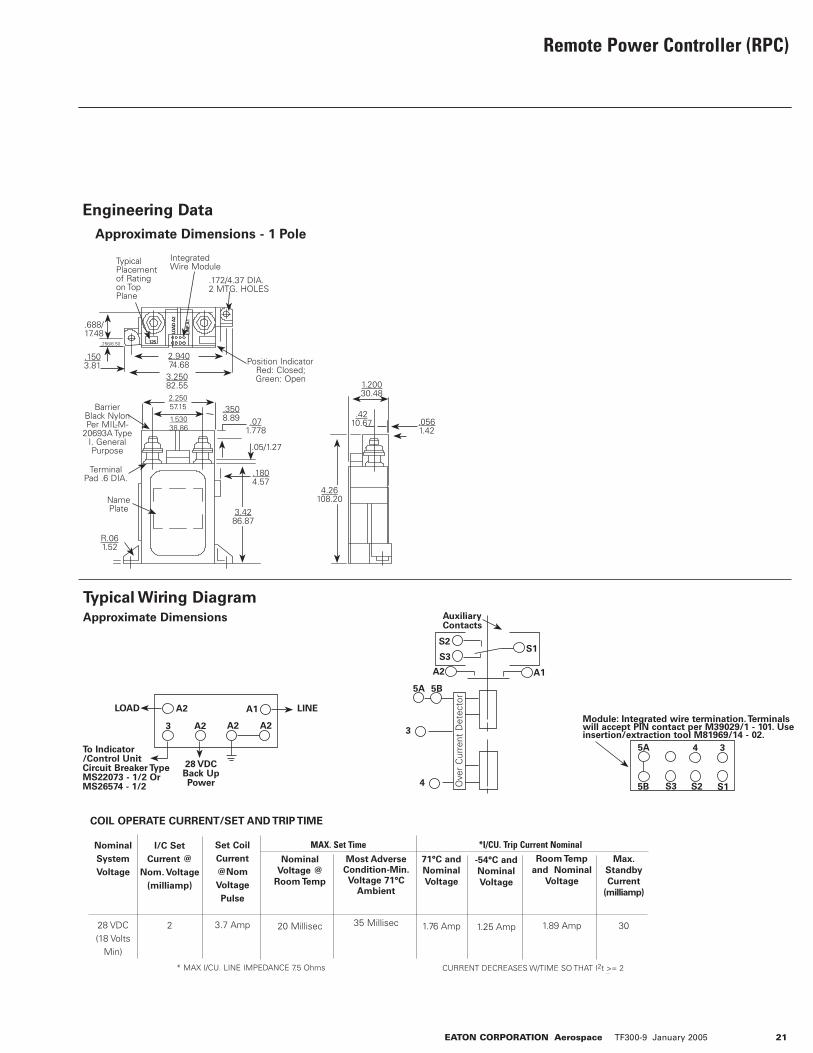
Remote Power Controller (RPC)
Engineering Data
Typical Wiring Diagram
Approximate Dimensions
A2 A1
3 A2 A2 A2
LOAD LINE
28 VDCBack Up Power
To Indicator /Control Unit Circuit Breaker Type MS22073 - 1/2 Or MS26574 - 1/2
S2
S3S1
A1A2
Auxiliary Contacts
Ove
r C
urre
nt D
etec
tor
5A 5B
3
4
5A 3
5B S3 S2 S1
4
Module: Integrated wire termination. Terminals will accept PIN contact per M39029/1 - 101. Use insertion/extraction tool M81969/14 - 02.
COIL OPERATE CURRENT/SET AND TRIP TIME
Nominal
System
Voltage
28 VDC (18 Volts
Min)
I/C Set
Current @
Nom. Voltage
(milliamp)
2
Set Coil
Current
@Nom
Voltage
Pulse
3.7 Amp
Nominal
Voltage @
Room Temp
20 Millisec
MAX. Set TimeMost Adverse
Condition-Min. Voltage 71°C
Ambient
35 Millisec
*I/CU. Trip Current Nominal
71°C and
Nominal
Voltage
1.76 Amp
-54°C and
Nominal
Voltage
1.25 Amp
Room Temp
and Nominal
Voltage
1.89 Amp
Max.
Standby
Current
(milliamp)
30
* MAX I/CU. LINE IMPEDANCE 7.5 Ohms CURRENT DECREASES W/TIME SO THAT I2t >= 2
Typical Placement of Rating on Top Plane
LOA
D A
2
LIN
E A
1
125
.172/4.37 DIA.2 MTG. HOLES
.688/17.48
2.94074.68
3.25082.55
Position IndicatorRed: Closed; Green: Open
1.53038.86
2.25057.15 .350
8.89 .071.778
.05/1.27
.1804.57
3.4286.87
Name Plate
R.061.52
4.26108.20
.0561.42
.4210.67
1.20030.48
Integrated Wire Module
.256/6.50
.1503.81
Barrier Black Nylon Per MIL-M-
20693A Type I. General Purpose
Terminal Pad .6 DIA.
Approximate Dimensions - 1 Pole

22 EATON CORPORATION Aerospace TF300-9 January 2005
Power Relays — Gasket Sealed - 100 Amps to 1,000 Amps
Typical Characteristics
Specifications• Design to meet the general requirements of MIL-R-6106 Type II continuous Duty Unsealed• Contacts are covered & gasketed• Double break contacts• All units are thermal breaker compatible at rated relay resistive load• Some models available with auxiliary circuits• Gold-plated auxiliary contacts for low-level applications available• Auxiliary contacts ratings: 28 Vdc: 5 amps resistive 3 amps inductive 2.5 amps lamp
Ratings Per MIL-R-6106:• Salt spray, humidity, accelera- tion, sand & dust, intermedi- ate current• Vibration: 5 to 10 Hz -.08 DA 10 to 55 Hz -.05 DA 55 to 500 Hz -2.0 g's• Shock: 25 g's (6-9 MS ½ sine wave)• Life: (-55 to 71°C) 50,000 cycles electrical at full rated load 100,000 cycles mechanical tested at 25% rated load• Altitude: 50,000 feet
Typical Characteristics (Figures 1 through 8)(For additional details, contact your local Eaton Technical Sales Representative)
• Power Contact Voltage Drop: Initial 0.15 V After Life Test: 0.175 V• Insulation Resistance: Initial 200 Meg ohm.• After Life Test: 100 Meg ohm
Dielectric Withstanding Voltage:
2.5 Seconds Sea Level
Initial: 1250 VAfter Life Test: 1000 VPower Contacts: 650 V
50,000 Feet 60 Seconds
Initial & After Life Test: 500 V
Circuit Diagrams
A1 A2
X1
X2 X1
X2
A1
13
12
11
A2
23
22
21
A2
X1
X2
B1
A1
12
11
11
A2
23
22
21
#1
#2 #3
Part
Number
Rated Contact Load Rupture
Current
Contact Rating
28 Vdc Intermittent Power
28 Vdc
Res. Ind. Motor Intermediate 15
Minute
5
Minute
1
Minute
Max.6
Inrush
SM100D2 SM100D3 SM150D1SM150D2SM150D3SM150D4SM150D53
SM200D1SM200D2SM200D3SM400D1SM400D2SM400D3SM1000D119
100100
1505
1505
1505
1505
1502002002004004004001000
80805050505050100100100100100100—
100100
15011501150115011501200200200400400400—
44151515151520202040404050
10001000120012001200120012002000200020004000400040006000
1301301951951951951952602602605205205201200
1501502252252252252253003003006006006001500
200200300300300300300400400400800800800
2000
600600900900900900900120012001200240024002400
2500�
1 600 Amp make, 200 Amp break2Duty cycle: 1 minute on, 1 minute off; 1 minute on, 20 minutes off3Maximum vibration 2000 Hz 2 g’s4Duty cycle: 1.5 minutes on, 3 minutes off5Will carry 200 Amps at 20% on duty cycle per minute6Maximum inrush provided coil voltage as noted is maintained7Operate time at 28 Vdc & 25 deg. C.8Contact bounce is average of 5 consecutive ratings.9Available in normal closed circuit.� 1 sec. on, 60 sec. off
EATON CORPORATION Aerospace TF300-9 January 2005 23
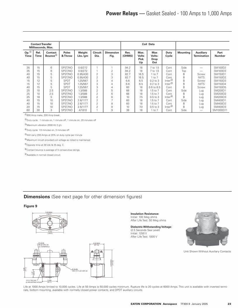
Power Relays — Gasket Sealed - 100 Amps to 1,000 Amps
Insulation Resistance:
Initial: 100 Meg ohmsAfter Life Test: 50 Meg ohms
Dielectric Withstanding Voltage:
(2.5 Seconds Sea Level)Initial: 1250 VAfter Life Test: 1000 V
Dimensions (See next page for other dimension figures)
Figure 9
3.0
6(7
7.7
)
1.2
7(3
2.2
)
.312 (7.92) DIA.(2) MOUNTING HOLES
X1 & X2#6-32 UNC-2A(2) TERMINALS
2.406(61.1)
2.25 MAX(57.15)
4.3
8 M
AX
(111.2
)
5.50 MAX(139.7)
4.312(109.5)
A1 & A2.500 (12.7)-20 UNF-2A
A2 A1
Life at 1000 Amps limited to 10,000 cycles. Life at 50 Amps is 50,000 cycles minimum. Rupture life is 20 cycles at 6000 Amps. This unit is available with inverted termi-nals, bottom mounting, available with normally closed power contacts, and DPDT auxiliary circuits.
Unit Shown Without Auxiliary Contacts
Contact Transfer
Milliseconds, Max.
Coil Data
Op.6
Time
Rel.
Time
Contact
Bounce8Poles
& Throw
Weight
Lbs./gm
Circuit
Dia.
Dimension
Fig.
Res.
(OHMS)
Max.
Volts
Pick
Up
Max
Volts-
Drop
Out
Duty
Cycle
Mounting Auxiliary
Termination
Part
Number
3535404015154025252540402060
1515151512121510101815151530
6655555
2.52.551010103
SPST/NOSPST/NOSPST/NOSPST/NO
SPDTSPDTSPDT
SPST/NOSPST/NOSPST/NOSPST/NOSPST/NOSPST/NOSPST/NO
0.6/2720.6/2720.95/4300.95/4301.25/5671.25/5671.25/5671.3/5881.3/5881.3/5882.6/11772.6/11772.6/11774/1810
11223332222221
12334445667889
94.294.282.782.76.66.66066661060601038
1818
16.516.56.56.51818187.518187.018
7 to 1.57 to 1.51 to 71 to 7
0.2 to 30.2 to 3
0.6 to 8.51.5 to 71.5 to 70.5 to 31.5 to 71.5 to 70.5 to 31 to 7
ContContContCont
Inter2Inter2ContContCont
Inter4ContCont
Inter4Cont
SideTopBBBBB
SideBB
SideBB
Side
——
ScrewIWTSScrewIWTSScrew
LugLugLugLugLugLug—
SM100D2SM100D3SM150D1SM150D2SM150D3SM150D4SM150D5SM200D1SM200D2SM200D3SM400D1SM400D2SM400D3
SM1000D11
1600 Amp make, 200 Amp break
2Duty cycle: 1 minute on, 1 minute off; 1 minute on, 20 minutes off
3Maximum vibration 2000 Hz 2 g’s
4Duty cycle: 1.5 minutes on, 3 minutes off
5Will carry 200 Amps at 20% on duty cycle per minute
6Maximum inrush provided coil voltage as noted is maintained
7Operate time at 28 Vdc & 25 deg. C.
8Contact bounce is average of 5 consecutive ratings.
9Available in normal closed circuit.

Power Relays — Gasket Sealed - 100 Amps to 1,000 Amps
Dimension Figures
Figure 1 Figure 2
Figure 3 Figure 4
X1 X2
1.875(47.62)
2.385(60.55)
.937 (23.8)
.219 (5.56) DIA.(2) MOUNTING
HOLES
.422 (10,7)
2.68(68.0)
#6-32 UNC-2A2 COIL TERM
1.7
2(4
3.6
9)
.98
6(2
5.0
)
.625(15.87)
2.22(56.38)
2.7
5(6
9.8
5)
.250(6.35)-28 UNF-3A2 Power Term
SM100D2 SM100D3
SM150D4
Unit Shown Without Auxiliary Contacts
2.64(67)
.219(5.56) DIA. MOUNTING HOLES
1.312(33.3)
2.6
8(6
8)
2.22(56.3)
2.188(55.5)
.250 (6.35)-28 UNF-3A2 POWER TERM
.625(15.8)
2.68(68)
1.7
2(4
3.6
)
X2 X1
SM150D1
SM150D2
SM150D3
SM150D5
SM150D4
SM150D2
24 EATON CORPORATION Aerospace TF300-9 January 2005
Unit Shown Without Auxiliary Contacts
X2X1
A2A1
WILL ACCEPT TERMINAL-PINCONNECTION (DEUTSCH PARTNO. 1841-1-5620)
.203 (5.15) ± .005 DIA.4 MOUNTING HOLES
2.75
(69.
8)
187
MTG
(47.
5)2.
19(5
5.6)
1.87 MTG(47.5)
4.50
(114
.3)
2.25(57.1)
2.25(57.1)
#6-32 UNC-2A6 AUX. TERMINALS
#6-32 UNC-2A2 COIL TERMINALS
.75(19)
.250 (6.35)-28 UNF-2A2 POWER TERMINALS
X2X1
B2B3
A2A1
.250 (6.35)-28 UNF-2A4 POWER TERMINALS
WILL EXCEPT TERMINAL-PINCONNECTION (DEUTSCH PARTNO 1841-1-5620)
.203 (5.15) ± .005 DIA.4 MOUNTING HOLES
2.75
(69.
8)
187
MTG
(47.
5)
2.19
(55.
6)
1.87 MTG(47.5)
4.50
(114
.3)
2.25(57.1)
2.25(57.1)
#6-32 UNC-2A6 AUX. TERMINALS
#6-32 UNC-2A2 COIL TERMINALS
.75(19)
.75(19)
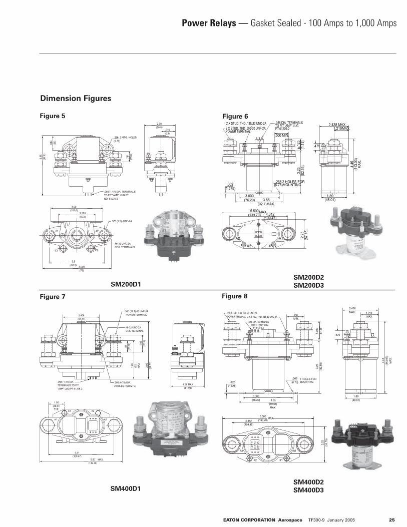
Power Relays — Gasket Sealed - 100 Amps to 1,000 Amps
Dimension Figures
Figure 5 Figure 6
Figure 7 Figure 8
SM200D1
SM400D1
SM200D2
SM200D3
SM400D2
SM400D3
EATON CORPORATION Aerospace TF300-9 January 2005 25
2.00(50.8)
.916(23)
.984 (25)
3.85
(97.
8)
.266 2 MTG. HOLES(6.75)
.781
(1
9.8)
X2X1
A2A1
4.00(101.6)
2.395(60.8)
3.5(68.9)
4.500(76)
.375 (9.5)- UNF-2A
#6-32 UNC-2ACOIL TERMINALS
.058 (1.47) DIA. TERMINALSTO FIT "AMP" LUG PT.NO. 61276-2
.058 (1.47) DIA. TERMINALS TO FIT"AMP" LUG PT 61276-2
4.38 MAX(61.93)
4.31(109.47)
1.05(26.67)TYP.
5.50(139.70)
1.06
(26.
9)3.
92(9
9.57
)
1.28 (32)
MAX
.81
(20.
57)
2.406(61.11)
.500 (12.7)-20 UNF-2APOWER TERMINAL
#6-32 UNC-2ACOIL TERMINAL
.266 (6.76) DIA.2 HOLES FOR MTG
MAX.
A2A1
X1 X2
.058 DIA. TERMINALS TO FIT "AMP" LUG
PT 61276-2
1.219 MAX.
.266(6.76)
2 HOLES FOR MOUNTING
3.25
(82.
55)
3.000(76.20) 3.53
(89.66)MAX.
1.89(48.01)
1.00
0±.
125
.475
.500MIN.
5.500(139.70)
MAX.
.062(1.575)
4.45
(113
.03)
MAX
.
2.438 MAX.
4.312(109.47)
2.25
(57.
15)
A2
X2 X1
A1
2 X STUD, THD .138-32 UNC-2A2 X STUD, THD .500-20 UNF-2APOWER TERMINAL
.058 DIA. TERMINALSTO FIT “AMP” LUGPT 61276-2 1.219 MAX.
.266(6.76)
2 HOLES FOR MOUNTING
3.25
(82.
55)
3.000(76.20) 3.65
(92.7)MAX.
1.89(48.01)
±.12
5(1
.13)
.475
.500 MIN.
5.500(139.70)
MAX.
.062(1.575)
4.45
(113
.03)
MAX
.
2.438 MAX.
4.312(109.47)
2.25
(57.
15)
A2
X2 X1
A1
2 X STUD, THD .138-32 UNC-2A2 X STUD, THD .500-20 UNF-2APOWER TERMINAL
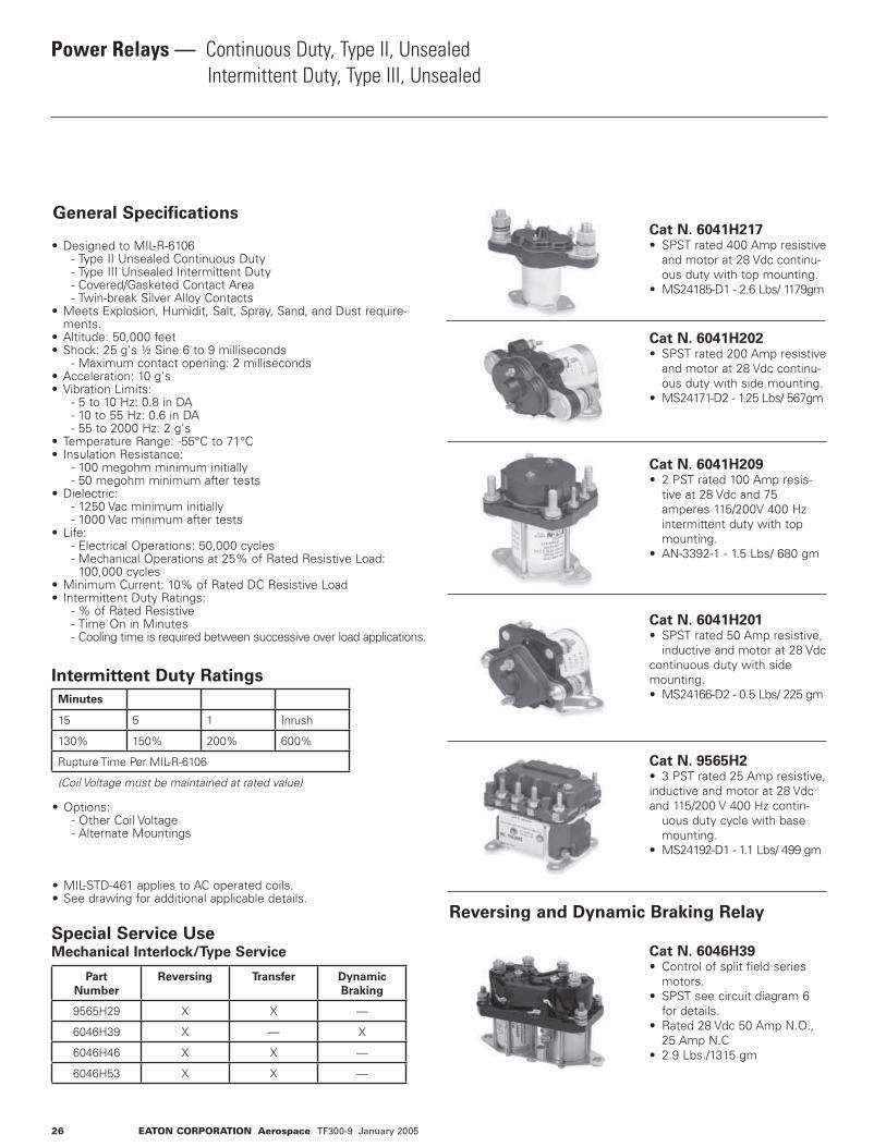
Power Relays — Continuous Duty, Type II, Unsealed Intermittent Duty, Type III, Unsealed
General Specifications
• Designed to MIL-R-6106 - Type II Unsealed Continuous Duty - Type III Unsealed Intermittent Duty - Covered/Gasketed Contact Area - Twin-break Silver Alloy Contacts• Meets Explosion, Humidit, Salt, Spray, Sand, and Dust require- ments.• Altitude: 50,000 feet• Shock: 25 g's ½ Sine 6 to 9 milliseconds - Maximum contact opening: 2 milliseconds• Acceleration: 10 g's• Vibration Limits: - 5 to 10 Hz: 0.8 in DA - 10 to 55 Hz: 0.6 in DA - 55 to 2000 Hz: 2 g's• Temperature Range: -55°C to 71°C• Insulation Resistance: - 100 megohm minimum initially - 50 megohm minimum after tests• Dielectric: - 1250 Vac minimum initially - 1000 Vac minimum after tests• Life: - Electrical Operations: 50,000 cycles - Mechanical Operations at 25% of Rated Resistive Load: 100,000 cycles• Minimum Current: 10% of Rated DC Resistive Load• Intermittent Duty Ratings: - % of Rated Resistive - Time On in Minutes - Cooling time is required between successive over load applications.
Intermittent Duty Ratings
• Options: - Other Coil Voltage - Alternate Mountings
• MIL-STD-461 applies to AC operated coils.• See drawing for additional applicable details.
Cat N. 6041H217• SPST rated 400 Amp resistive and motor at 28 Vdc continu- ous duty with top mounting.• MS24185-D1 - 2.6 Lbs/ 1179gm
Cat N. 6041H202• SPST rated 200 Amp resistive and motor at 28 Vdc continu- ous duty with side mounting.• MS24171-D2 - 1.25 Lbs/ 567gm
Cat N. 6041H209• 2 PST rated 100 Amp resis- tive at 28 Vdc and 75 amperes 115/200V 400 Hz intermittent duty with top mounting.• AN-3392-1 - 1.5 Lbs/ 680 gm
Cat N. 6041H201• SPST rated 50 Amp resistive, inductive and motor at 28 Vdc continuous duty with side mounting.• MS24166-D2 - 0.5 Lbs/ 225 gm
Cat N. 9565H2• 3 PST rated 25 Amp resistive, inductive and motor at 28 Vdc and 115/200 V 400 Hz contin- uous duty cycle with base mounting.• MS24192-D1 - 1.1 Lbs/ 499 gm
Cat N. 6046H39• Control of split field series motors.• SPST see circuit diagram 6 for details.• Rated 28 Vdc 50 Amp N.O., 25 Amp N.C• 2.9 Lbs./1315 gm
26 EATON CORPORATION Aerospace TF300-9 January 2005
Minutes
15 5 1 Inrush
130% 150% 200% 600%
Rupture Time Per MIL-R-6106
(Coil Voltage must be maintained at rated value)
Special Service UseMechanical Interlock/Type Service
Part
Number
Reversing Transfer Dynamic
Braking
9565H29 X X —
6046H39 X — X
6046H46 X X —
6046H53 X X —
Reversing and Dynamic Braking Relay

Power Relays — Continuous Duty, Type II, Unsealed Intermittent Duty, Type III, Unsealed
EATON CORPORATION Aerospace TF300-9 January 2005 27
Eaton Part
Number
Government
Part
Number
Continuous Power Contacts, Ratings Contacts Operate
Milliseconds, Maximum
Coil Data
28VDC 115/200 VAC 400 HZ. Contact
Bounce
Poles &
Throw4Weight
Lbs./GMS
Circuit
Dia./
Dim.
Figure
Resistance
(OHMS)± 10%
Pickup/Sealed
Volts
Pickup5Volts
Drop-
out6
Duty
Cycle
Mounting Coil
Voltage
NominalRES. IND. MOTOR RES. IND. MOTOR OP.
TIME
REL
TIME
9565H2
9565H29
9565H95
6041H532
6041H2202
6041H230
6046H392
6041H201
6041H149
6041H200
9565H94
6041H219
6041H80
6041H144
6041H11
6041H209
6046H53
9565H13
6041H202
6041H105
6041H123
6041H203
6041H212
6041H215
6041H216
6046H46
6041H205
6041H217
6041H218
6041H206
MS24192-D2MS24152-D1
——
MS24187-D1
MS24187-D2
—MS24166-D2
—MS24166-D1MS24193-D1MS24178-D1
———
AN3362-1MS25031-D1B
—MS24171-D2
——
MS24172-D2—
MS24171-D1MS24172-D1MS25032-D1MS24185-D2MS24185-D1MS24179-D1MS24179-D2
252525
50/25
50/25
50/25
50/255050505055100100100100100100200200200200200200200200400400400400
252525
50/25
50/25
50/25
50/255050505040808080808075100100100100100100100100100100100100
252525
50/25
50/25
50/25
50/255050505040808080808075
200200200200200200200150400400400400
252525
25/25
25/25
25/25
————5055———7575100———————
150————
252525—
—
—
————50———————————————————
252525—
—
—
————5035———656575———————
100————
20202020
20
20
—20202020—
35
2225—40254025254040402020
15151515
15
15
—10151015—
10
1510—15181510101515151515
666
5 N.O./10 N.C.
5 N.O./10 N.C.
5 N.O./10 N.C.—5554—
3.5
450—5555555555
3PST3PDT3PSTSPDT
SPDT
SPDT
SPDTSPSTSPSTSPST3PSTDPSTSPSTSPSTSPSTDPSTDPDT3PSTSPSTSPSTSPSTSPSTSPSTSPSTSPSTDPDTSPSTSPSTSPSTSPST
1.1/4982/909.09
1.06/482.95.54/245.45
.54/245.45
.54/245.45
2.9/1318.18.50/225
.56/254.55.50/2251.51/685
.75/340.911.4/636.361.4/636.361.4/636.36
1.5/6853.5/1590.912.5/1136.361.25/568.181.25/868.181.3/590.911.23/560
1.3/590.911.33/604.551.33/604.555.5/2500.002.6/1181.822.6/1181.822.6/1181.822.6/1181.82
10 / 1116 / 1110 / 114 / 2
4 / 2
4 /2
6 / 71 / 41 / 41 / 4
10 / 112 / 21 / 31 / 31 / 12 / 29 / 7
12 / 111 / 51 / 51 / 51 / 51 / 51 / 11 / 1 8 / 71 / 51 / 11 / 11 / 5
/ 6022 / 92/ 116016.9
94.2
94.2
2694.216.994.2
13.5 / 71.566
66.366.366.34343
9 / 5366
10 (+15/-10)66
10 (+15/-10)6666
10(+15/-10)4160601010
1818708.2
18
18
18188.2181818181818201818189187.518187.518181877
1.5 to 71.5 to 78 to 38
0.8 to 4.8
1.5 to 9
1.5 to 9
71.5 to 7
0.8 to 4.81.5 to 71.5 to 71.5 to 71.5 to 71.5 to 71.5 to 71.5 to 71.5 to 71.5 to 71.5 to 7
3.51.5 to 7
0.5 to 3.01.5 to 71.5 to 7
0.5 to 3.01.5 to 71.5 to 71.5 to 7
0.5 to 3.00.5 to 3.0
CONTCONTCONTCONT
CONT
CONT
CONTCONTCONTCONTNote1
CONTCONTCONTNote1
CONTCONTCONTCONTCONT
INTER3
CONTCONT
INTER3
CONTCONTCONT
INTER3
INTER3
BASEBASEBASETOP
TOP
TOP
TOPSIDESIDETOP
BASETOPSIDESIDETOPTOPTOP
BASESIDESIDESIDESIDESIDETOPTOPTOPSIDETOPTOPSIDE
28 dc28 dc120 dc12 dc
28 dc
29 dc
28 dc28 dc12 dc28 dc28 dc28 dc28 dc28 dc28 dc28 dc28 dc28 dc28 dc12 dc28 dc28 dc28 dc28 dc28 dc28 dc28 dc28 dc28 dc28 dc
MS Part Number Summary
AN3362-1* 6041H209 MS24179-D1 6041H218
MS24152-D1* 9565H29* MS24185-D2 6041H205
MS24166-D1 6041H200 MS24187-D1 6041H220
MS24166-D2 6041H201 MS24187-D2 6041H230
MS24171-D1 6041H215 MS24192-D1 9565H2
MS24171-D2 6041H202 MS24193-D1 9565H94
MS24172-D1 6041H216 MS25031-D1B 6046H53
MS24172-D2 6041H203 MS24185-D1 6041H217
MS24178-D1 6041H219 MS25032-1 6046H46
*Inactive for new design
Conversion Part Number
AN Part Number Use MS Part Number Eaton Part Number
3343-1 — 9565H13
3350-1 MS24166-D2 6041H201
3362-1 — 6041H209
3370-1 MS24171-D2 6041H202
3371-1 MS24172-D2 6041H203
3380-1 MS24185-D2 6041H205
— MS25030-D1B 6041H51
3381-2 MS24179-D1 6041H218
1 Coil will exceed 95° C temperature rise when left on continuously in 25° ambi- ent, but will not be damaged. At maximum ambient temperture of 71°C, the duty cycle should be limited to 15 minutes “on” time per half hour to obtain maximum coil life. 2 Continuous and intermittent duty ratings shown are for N.O. pole rated at 1/2 the listed continuous DC duty ratings. N.C. pole on 6041H53 and H220 limited to 15 g’s shock. 3 Time on 1 1/2 minutes at 29 Vdc. Minimum time off is 3 minutes.
4 All continuous duty resistive and motor load ratings and all intermittent duty rat- ings for all 3 pole relays listed under 28 Vdc apply for 120 Vdc systems with all 3 poles of the relay connected in the series. 5 Pick-up voltage below values shown may cause relay to rapidly cycle on and off (chatter). 6 Relay must drop-out at voltage value or less and may drop-out at any voltage below the higher voltage noted.
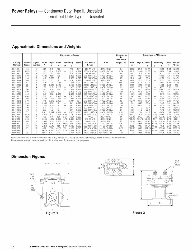
Dimensions in Inches Dimensions
in
Millimeters
Dimensions in Millimeters
Catalog
Number
Ampere
Ratings
Figure
Number
Wide
A
High
B
Deep
C
Mounting Hole F Net Stud G
Power
Coil Weight Lbs. Wide
A
High B Deep Mounting Hole
F
Weight
GramsD E C D E
6041H116041H536041H806041H1056041H1236041H1446041H1496041H2006041H2016041H2026041H2036041H2056041H2066041H2096041H2126041H2156041H2166041H2176041H2186041H2196041H2206046H396046H466046H539565H29565H139565H299565H949565H95
10050/25100200200100505050
20020040040010020020020040040055
50/2550/2520010025100255025
1235634245555251111227771111121111
3.272.632.914.4064.53.332.752.752.754.414.55.55.5
3.4694.484.4064.4065.55.5
2.9222.8124.827.6886.6883.0633.8124.75
3.6253.063
3.133.14
33.283.575
32.5
2.6252.53.283.3133.923.923.4063.3133.753.754.54.5
2.8443.133.454.1253.752.753.5462.75
3.1882.75
2.082.0622.081.99
22
2.1252.1252.1251.99
22.4382.4382.6562.466
2222
2.0312.0622.253.4682.6562.753.284.1253.3122.75
————————————————————
1.3952.011.76
2.1252.6882.4682.752.135
2.752.22.262.3952.3952.261.8752.1881.8752.3952.3952.4062.4062.9483.7173.013.013.013.01
2.3852.2
4.3016.8956.022.493.1024.1872.3222.494
0.270.2140.2760.2760.2760.2760.2290.2190.2290.2760.2760.2760.2760.2760.270.2760.2760.2760.2760.2230.2140.2280.2660.2660.2290.2250.218
0.2190.229
.250-28 UNF.190-32 UNF-2A
.250-32 UNC.375-24 UNF-2A.375-24 UNF-2A
.250-28 UNF.190-32 UNC-2A.191-32 UNC-2A.190-32 UNC-2A.375-24 UNF-2A.375-24 UNF-2A.500-20 UNF-2A.500-20 UNF-2A.250-28 UNF-2B.375-24 UNF-2A.375-24 UNF-2A.375-24 UNF-2A.500-20 UNF-2A.500-20 UNF-2A.190-32 UNC-2B.190-32 UNF-2A
.190-32.375-24 UNF .250-28 UNF
.190-32 UNF-2B
.250-28 UNF-2B
.190-32 UNF-2B.190-32 UNF-2B.190-32 UNF-2B
.138-32 UNC.138-32 UNC-2A.138-32 UNC-2A.138-32 UNC-2A.138-32 UNC-2A
.138-32 UNC.138-32 UNC-2A.138-32 UNC-2A.138-32 UNC-2A.138-32 UNC-2A.138-32 UNC-2A.138-32 UNC-2A.138-32 UNC-2A.138-32 UNC-2B.138-32 UNC-2A.138-32 UNC-2A.138-32 UNC-2A.138-32 UNC-2A.138-32 UNC-2A.138-32 UNC-2B.137-32 UNC-2A
.138-32 UNC
.138-32 UNC
.138-32 UNC.138-32 UNC-2B.164-32 UNC-2B.164-32 UNC-2B.164-32 UNC-2B.164-32 UNC-2B
1.40.541.41.251.31.4
0.5620.50.51.251.232.62.61.51.31.331.332.62.60.750.542.95.53.5
1.0622.52.251.51.06
83.0666.873.91111.92112.0184.5869.8569.8569.85112.01114.3139.7139.788.11113.79111.91111.91139.7139.774.2271.42
122.43195.28169.88
77.896.82120.6592.0877.8
79.57907676.2
83.3190.8176.263.566.6863.583.3184.1599.5799.5786.5184.1595.2595.25114.3114.372.2479.587.63
104.7895.2569.8590.0769.8580.9869.85
52.8352.3752.8350.5550.850.853.9853.9853.9850.5550.861.9361.9367.4662.6450.850.850.850.851.5952.3757.1588.0967.4669.8583.31104.7884.1269.85
————————————————————
35.4351.0544.753.9868.2862.6969.8554.23
69.8555.8857.4
60.8362.8357.447.6355.5847.6360.8360.8361.1161.1174.8894.4176.4576.4576.4576.4560.5855.88109.25175.13152.9163.2578.79106.3558.9863.35
6.865.447.017.017.017.015.825.565.827.017.017.017.017.016.867.017.017.017.015.665.445.796.766.765.825.725.545.565.82
636.36245.45636.36568.18590.91636.36255.68
225225
568.18560
1181.821181.82681.82590.91604.55604.551181.821181.82340.91245.451318.18
25001590.91482.951136.361022.73681.82481.82
28 EATON CORPORATION Aerospace TF300-9 January 2005
Power Relays — Continuous Duty, Type II, Unsealed Intermittent Duty, Type III, Unsealed
Approximate Dimensions and Weights
Note: All coils and auxiliary terminals are 6-32, except for Catalog Number 9565 relays which have 8-32 coil terminals.Dimensions are approximate and should not be used for construction purposes.
Dimension Figures
Figure 1 Figure 2
B
E
C
A
DIA. GTERM.STUD
DIA. FMTG.
HOLES
A4
A2 A1 CA3
X2 X2
DIA. G. TERM.STUDS
DIA. F MTG. HOLES
AE
B

EATON CORPORATION Aerospace TF300-9 January 2005 29
Power Relays — Continuous Duty, Type II, Unsealed Intermittent Duty, Type III, Unsealed
Dimension Figures (cont.)
Figure 3 Figure 4 Figure 5 Figure 6
Figure 7 Figure 11 Figure 12
A
C
X2
A2 A1
X1
E
F DIA.MTG. HOLES
C DIA.TERM.STUDS
F
A
G DIA.TERM.STUDSB
B
EF DIA.MTG.
HOLES
A
EF DIA.MTG.
HOLES
C
G DIA.TERM.STUDSB
G DIA.TERM.STUDS
B
A
EF DIA.MTG.
HOLES
C
C
B
EF DIA.MTG.HOLES
G DIA.TERMSTUDS
D
A
B
G DIA.TERM.STUDS
F DIA.MTG. HOLES E
D C
A
B
D
G DIA.TERM. STUDS
F DIA.MTG. HOLES
AE
C

Power Relays — Continuous Duty, Type II, Unsealed Intermittent Duty, Type III, Unsealed
Typical Wiring Diagrams
Diagram 1 Diagram 2 Diagram 3 Diagram 4
Diagram 8 Diagram 9 Diagram 10
Diagram 12 Diagram 16 Diagram 18
30 EATON CORPORATION Aerospace TF300-9 January 2005
A1 A2
X1
X2
A1 A2
B1 B2
X1
X2
A1 A2
A3 A4
X1
X2
B1 B2
A1 A2
X1
X2
D1 D2
C1 C2
X3
X4
B1 B2
A1 A2
X1
X2
B4 A3
A4 A3
Y1
Y2
B1 B2
A1 A2
X1
X2
C1 C2
B1 B2
A1 A2
X1
X2
L1 T2
L1 T2
L1 T2
X1
X2
Y2
B1
A1
A2 B2 C2
C1
X2
X1
B3
A3
C3
Y1
X1
L2
L1
T1 T2 T3
L3
X2
X1
L12
L11
L13
X12
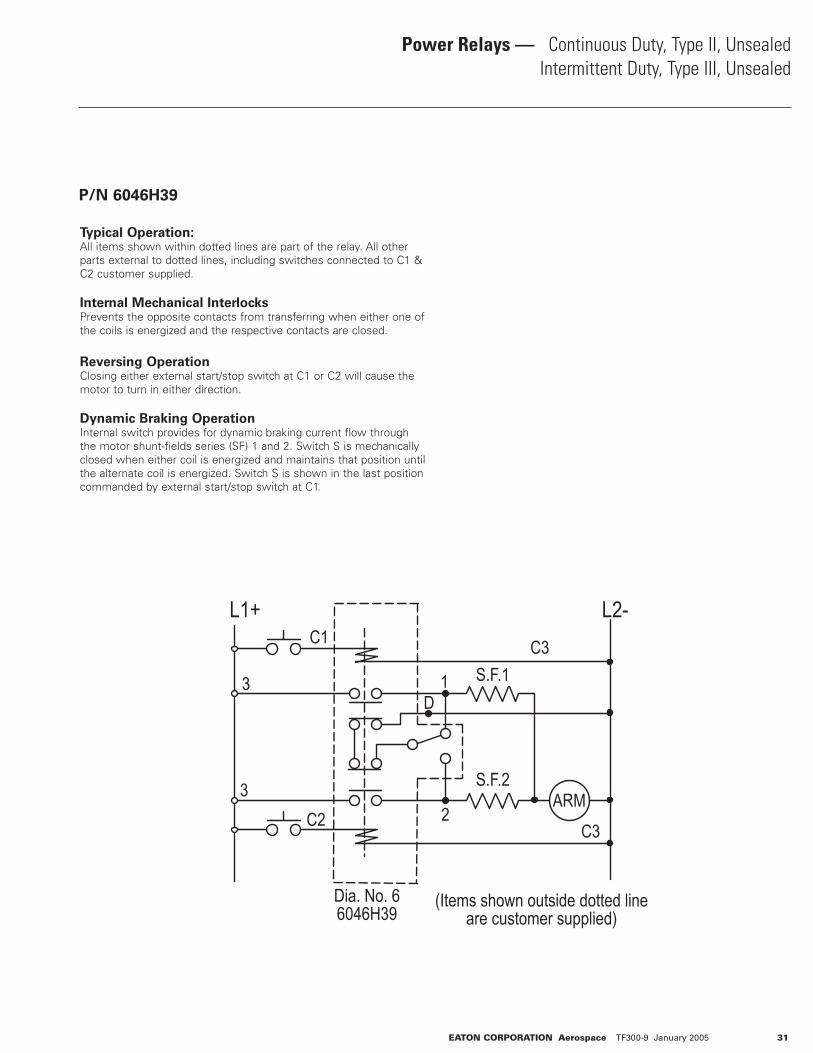
Power Relays — Continuous Duty, Type II, Unsealed Intermittent Duty, Type III, Unsealed
Typical Operation:All items shown within dotted lines are part of the relay. All other parts external to dotted lines, including switches connected to C1 & C2 customer supplied.
Internal Mechanical InterlocksPrevents the opposite contacts from transferring when either one of the coils is energized and the respective contacts are closed.
Reversing OperationClosing either external start/stop switch at C1 or C2 will cause the motor to turn in either direction.
Dynamic Braking OperationInternal switch provides for dynamic braking current flow through the motor shunt-fields series (SF) 1 and 2. Switch S is mechanically closed when either coil is energized and maintains that position until the alternate coil is energized. Switch S is shown in the last position commanded by external start/stop switch at C1.
P/N 6046H39
L1+ L2-C3
S.F.1
S.F.2ARM
1D
2
C1
3
3C2
Dia. No. 66046H39
(Items shown outside dotted lineare customer supplied)
C3
EATON CORPORATION Aerospace TF300-9 January 2005 31
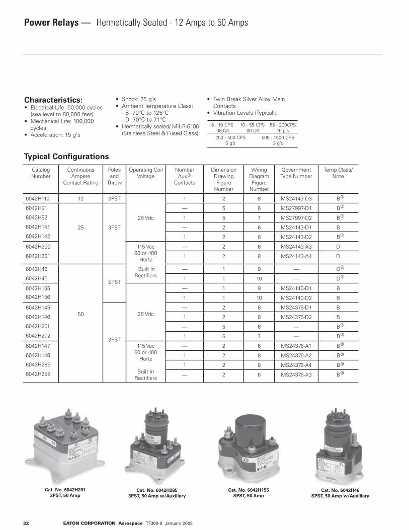
32 EATON CORPORATION Aerospace TF300-9 January 2005
Power Relays — Hermetically Sealed - 12 Amps to 50 Amps
Typical Configurations
Cat. No. 6042H201
3PST, 50 AmpCat. No. 6042H285
3PST, 50 Amp w/Auxiliary
Cat. No. 6042H46
SPST, 50 Amp w/Auxiliary
Cat. No. 6042H155
SPST, 50 Amp
Characteristics:• Electrical Life: 50,000 cycles (sea level to 80,000 feet)• Mechanical Life: 100,000 cycles• Acceleration: 15 g's
• Shock: 25 g's• Ambient Temperature Class: - B -70°C to 125°C - D -70°C to 71°C• Hermetically sealed/ MIL-R-6106 (Stainless Steel & Fused Glass)
• Twin Break Silver Alloy Main Contacts• Vibration Levels (Typical):
5 - 10 CPS.08 DA
10 - 55 CPS.06 DA
55 - 200CPS10 g’s
250 - 500 CPS5 g’s
500 - 1500 CPS3 g’s
Catalog Number
ContinuousAmpere
Contact Rating
Poles and
Throw
Operating Coil Voltage
Number Aux1
Contacts
Dimension Drawing Figure
Number
Wiring Diagram Figure
Number
Government Type Number
Temp Class/Note
6042H110 12 3PST
28 Vdc
1 2 8 MS24143-D3 B2
6042H91
6042H92
6042H141
6042H142
25 3PST
— 5 6 MS27997-D1 B3
1 5 7 MS27997-D2 B3
— 2 6 MS24143-D1 B
1 2 8 MS24143-D2 B7
6042H290
6042H291
115 Vac 60 or 400
Hertz
— 2 6 MS24143-A3 D
1 2 8 MS24143-A4 D
6042H45
6042H46
50
SPST
Built InRectifi ers
— 1 9 — D8
1 1 10 — D8
6042H155
6042H156
28 Vdc
— 1 9 MS24140-D1 B
1 1 10 MS24140-D2 B
6042H145
6042H146
6042H201
6042H2023PST
— 2 6 MS24376-D1 B
1 2 8 MS24376-D2 B
— 5 6 — B3
1 5 7 — B3
6042H147
6042H148
6042H285
6042H288
115 Vac 60 or 400
Hertz
Built In Rectifi ers
— 2 6 MS24376-A1 B�
1 2 8 MS24376-A2 B�
1 2 8 MS24376-A4 B�
— 2 6 MS24376-A3 B�

EATON CORPORATION Aerospace TF300-9 January 2005 33
Power Relays — Hermetically Sealed - 12 Amps to 50 Amps
Ratings
1 Auxiliary Switch: SPDT rated 28 Vdc and 115 V 400 Hz, 5 Amp Res. & Ind. & 0.75 Amp Lamp2 Rated 100,000 operations electrical and mechanical life; Auxiliary switch rated 1,25 Amp Res. & 0.75 Amp Ind.3 Rated by 50 g shock4 These Ratings for 115 V 400 Hz only5 See MS Sheets for details6 Intermittent duty ratings for general applications. (See chart below)7 Ratings for 50/60 Hz only @ 115/200 Vac8 Maximum ambient temperature at 400 Hz = 110°C9 400 Hz only � Temperature Class D for 60 Hz AC Operation
Power Contact Ratings -
Continuous Duty 6Coil Data Catalog
Number
28 Vdc 115/200 Vac 400 Hz Max. Coil Power Max.
Volts
Pick Up
at Amb.
Temp.
Volts
Amperes Amperes Hold Drop
OutRes. Ind. Motor Res. Ind. Motor Amps Volts
12 12 6 12
25
12
25
6
25
0.60.60.60.60.6
29 dc 18 dc 7 dc 1.5 dc 6042H1106042H916042H926042H1416042H142
25 25 25 0.225
124 ac 90 ac 40 ac9 10 ac
6042H2906042H291
504
354
0.150 6042H456042H46
504 504 504 0.500.50
29 dc 18 dc 7 dc 1.5 dc
6042H1556042H156
50 50 50
50 50 50 0.60.60.60.6
6042H1456042H1466042H2016042H202
50 50 50 0.225 124 ac 90 ac 40 ac 10 ac6042H1476042H1486042H2856042H288
Intermittent Duty Ratings
Continuous 15 Minutes 5 Minutes 1 Minute Max. Inrush
100% 130% 150% 200% 600%
In general, these power relays can withstand the above intermittent duty overcurrent.
Options:Internal Coil Suppression
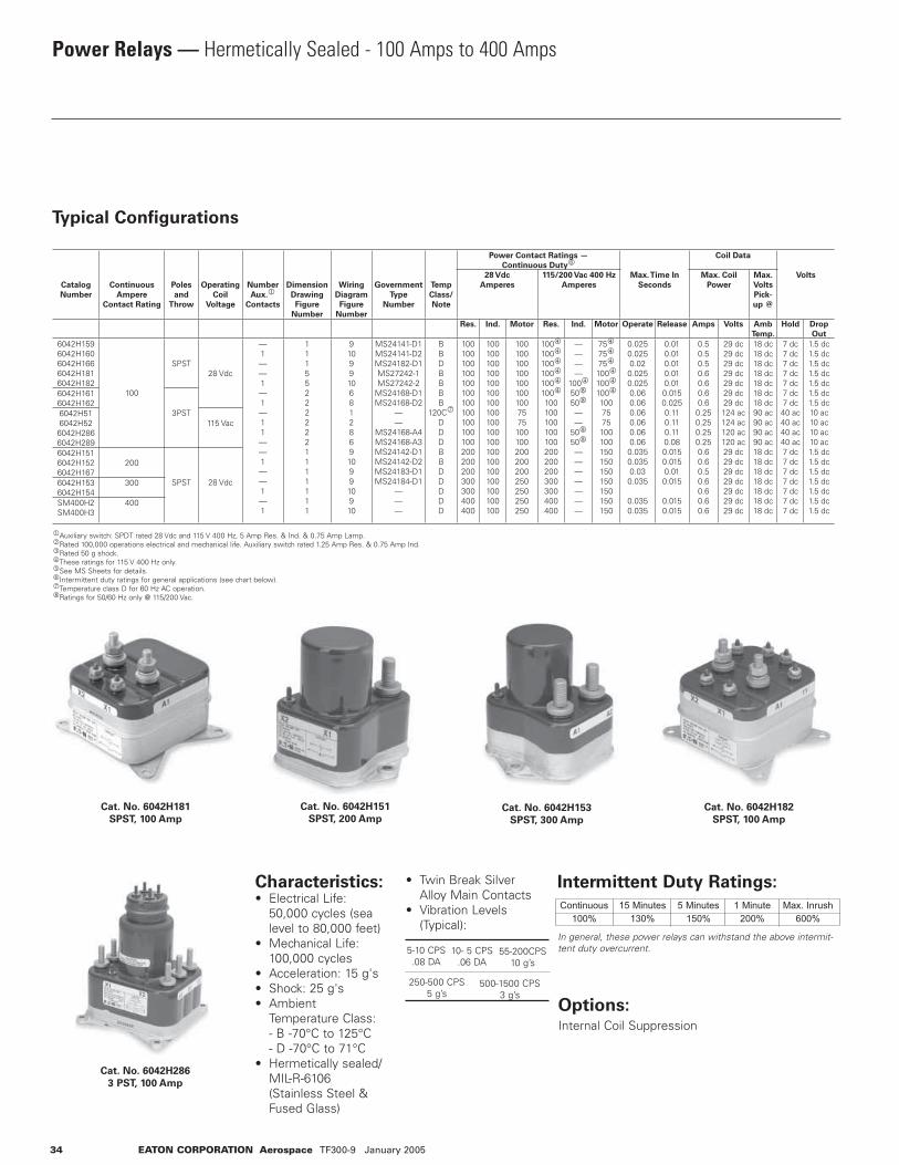
34 EATON CORPORATION Aerospace TF300-9 January 2005
Power Relays — Hermetically Sealed - 100 Amps to 400 Amps
Typical Configurations
Cat. No. 6042H181
SPST, 100 Amp
Cat. No. 6042H151
SPST, 200 Amp
Cat. No. 6042H182
SPST, 100 AmpCat. No. 6042H153
SPST, 300 Amp
Characteristics:• Electrical Life: 50,000 cycles (sea level to 80,000 feet)• Mechanical Life: 100,000 cycles• Acceleration: 15 g's• Shock: 25 g's• Ambient Temperature Class: - B -70°C to 125°C - D -70°C to 71°C• Hermetically sealed/ MIL-R-6106 (Stainless Steel & Fused Glass)
• Twin Break Silver Alloy Main Contacts• Vibration Levels (Typical):
Cat. No. 6042H286
3 PST, 100 Amp
1Auxiliary switch: SPDT rated 28 Vdc and 115 V 400 Hz, 5 Amp Res. & Ind. & 0.75 Amp Lamp.2Rated 100,000 operations electrical and mechanical life. Auxiliary switch rated 1.25 Amp Res. & 0.75 Amp Ind.3Rated 50 g shock.4These ratings for 115 V 400 Hz only.5See MS Sheets for details.6Intermittent duty ratings for general applications (see chart below).7Temperature class D for 60 Hz AC operation.8Ratings for 50/60 Hz only @ 115/200 Vac.
5-10 CPS.08 DA
10- 5 CPS.06 DA
55-200CPS10 g’s
250-500 CPS5 g’s
500-1500 CPS3 g’s
Intermittent Duty Ratings:
Continuous100%
15 Minutes130%
5 Minutes150%
1 Minute200%
Max. Inrush600%
In general, these power relays can withstand the above intermit-tent duty overcurrent.
Options:Internal Coil Suppression
Catalog
Number
Continuous
Ampere
Contact Rating
Poles
and
Throw
Operating
Coil
Voltage
Number
Aux.1
Contacts
Dimension
Drawing
Figure
Number
Wiring
Diagram
Figure
Number
Government
Type
Number
Temp
Class/
Note
Power Contact Ratings —
Continuous Duty6
Max. Time In
Seconds
Coil Data
Volts28 Vdc
Amperes
115/200 Vac 400 Hz
Amperes
Max. Coil
Power
Max.
Volts
Pick-
up @
Res. Ind. Motor Res. Ind. Motor Operate Release Amps Volts Amb
Temp.
Hold Drop
Out
6042H1596042H1606042H1666042H1816042H182
100
SPST28 Vdc
—1——1—1—11——1——1—1
111552222221111111
91099106812869109910910
MS24141-D1MS24141-D2MS24182-D1MS27242-1MS27242-2
MS24168-D1MS24168-D2
——
MS24168-A4MS24168-A3MS24142-D1MS24142-D2MS24183-D1MS24184-D1
———
BBDBBBB
120C7
DDDBBDDDDD
100100100100100100100100100100100200200200300300400400
100100100100100100100100100100100100100100100100100100
1001001001001001001007575100100200200200250250250250
1004
1004
1004
1004
1004
1004
100100100100100200200200300300400400
————
1004
508
508
——
508
508
———————
754
754
754
1004
1004
1004
1007575100100150150150150150150150
0.0250.0250.02
0.0250.0250.060.060.060.060.060.06
0.0350.0350.03
0.035
0.0350.035
0.010.010.010.010.010.0150.0250.110.110.110.080.0150.0150.010.015
0.0150.015
0.50.50.50.60.60.60.6
0.250.250.250.250.60.60.50.60.60.60.6
29 dc29 dc29 dc29 dc29 dc29 dc29 dc124 ac124 ac120 ac120 ac29 dc29 dc29 dc29 dc29 dc29 dc29 dc
18 dc18 dc18 dc18 dc18 dc18 dc18 dc90 ac90 ac90 ac90 ac18 dc18 dc18 dc18 dc18 dc18 dc18 dc
7 dc7 dc7 dc7 dc7 dc7 dc7 dc40 ac40 ac40 ac40 ac7 dc7 dc7 dc7 dc7 dc7 dc7 dc
1.5 dc1.5 dc1.5 dc1.5 dc1.5 dc1.5 dc1.5 dc10 ac10 ac10 ac10 ac1.5 dc1.5 dc1.5 dc1.5 dc1.5 dc1.5 dc1.5 dc
6042H1616042H162
3PST6042H516042H526042H2866042H289
115 Vac
6042H1516042H1526042H167
200
SPST 28 Vdc6042H1536042H154
300
SM400H2SM400H3
400
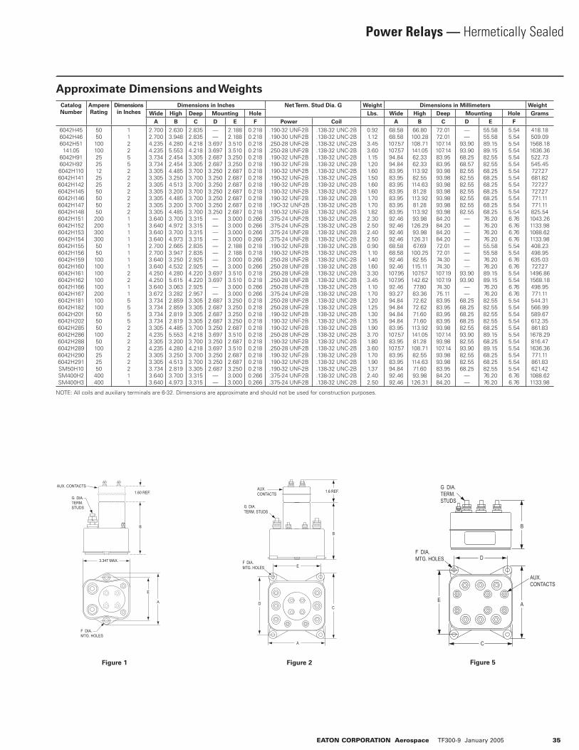
EATON CORPORATION Aerospace TF300-9 January 2005 35
Power Relays — Hermetically Sealed
Figure 1 Figure 2 Figure 5
Catalog
Number
Ampere
Rating
Dimensions
in Inches
Dimensions in Inches Net Term. Stud Dia. G Weight Dimensions in Millimeters Weight
Wide High Deep Mounting Hole Lbs. Wide High Deep Mounting Hole Grams
A B C D E F Power Coil A B C D E F
6042H456042H466042H51
141.056042H916042H926042H1106042H1416042H1426042H1456042H1466042H1476042H1486042H1516042H1526042H1536042H1546042H1556042H1566042H1596042H1606042H1616042H1626042H1666042H1676042H1816042H1826042H2016042H2026042H2856042H2866042H2886042H2896042H2906042H291SM50H10SM400H2SM400H3
5050100100252512252550505050
200200300300505010010010010010020010010050505010050100252550
400400
11225522222221111111122115555222222211
2.7002.7004.2354.2353.7343.7343.3053.3053.3053.3053.3053.3053.3053.6403.6403.6403.6402.7002.7003.6403.6404.2504.2503.6403.6723.7343.7343.7343.7343.3054.2353.3054.2353.3053.3053.7343.6403.640
2.6303.9484.2805.5532.4542.4544.4853.2504.5133.2004.4853.2004.4853.7004.9723.7004.9732.6653.9473.2504.5324.2805.6153.0633.2822.8592.8592.8192.8194.4855.5533.2004.2803.2504.5132.8193.7004.973
2.8352.8354.2184.2183.3053.3053.7003.7003.7003.7003.7003.7003.7003.3153.3153.3153.3152.8352.8352.9252.9254.2204.2202.9252.9573.3053.3053.3053.3053.7004.2183.7004.2183.7003.7003.3053.3153.315
——
3.6973.6972.6872.6873.2503.2503.2503.2503.2503.2503.250
————————
3.6973.697
——
2.6872.6872.6872.6873.2503.6973.2503.6973.2503.2502.687
——
2.1882.1883.5103.5103.2503.2502.6872.6872.6872.6872.6872.6872.6873.0003.0003.0003.0002.1882.1883.0003.0003.5103.5103.0003.0003.2503.2503.2503.2502.6873.5102.6873.5102.6872.6873.2503.0003.000
0.2180.2180.2180.2180.2180.2180.2180.2180.2180.2180.2180.2180.2180.2660.2660.2660.2660.2180.2180.2660.2660.2180.2180.2660.2660.2180.2180.2180.2180.2180.2180.2180.2180.2180.2180.2180.2660.266
.190-32 UNF-2B
.190-30 UNF-2B
.250-28 UNF-2B
.250-28 UNF-2B
.190-32 UNF-2B
.190-32 UNF-2B
.190-32 UNF-2B
.190-32 UNF-2B
.190-32 UNF-2B
.190-32 UNF-2B
.190-32 UNF-2B.19O-32 UNF-2B.190-32 UNF-2B.375-24 UNF-2B.375-24 UNF-2B.375-24 UNF-2B.375-24 UNF-2B.190-32 UNF-2B.190-32 UNF-2B.250-28 UNF-2B.250-28 UNF-2B.250-28 UNF-2B.250-28 UNF-2B.250-28 UNF-2B.375-24 UNF-2B.250-28 UNF-2B.250-28 UNF-2B.190-32 UNF-2B.190-32 UNF-2B.190-32 UNF-2B.250-28 UNF-2B.190-32 UNF-2B.250-28 UNF-2B.190-32 UNF-2B.190-32 UNF-2B.190-32 UNF-2B.375-24 UNF-2B.375-24 UNF-2B
.138-32 UNC-2B
.138-32 UNC-2B
.138-32 UNC-2B
.138-32 UNC-2B
.138-32 UNC-2B
.138-32 UNC-2B
.138-32 UNC-2B
.138-32 UNC-2B
.138-32 UNC-2B
.138-32 UNC-2B
.138-32 UNC-2B
.138-32 UNC-2B
.138-32 UNC-2B
.138-32 UNC-2B
.138-32 UNC-2B
.138-32 UNC-2B
.138-32 UNC-2B
.138-32 UNC-2B
.138-32 UNC-2B
.138-32 UNC-2B
.138-32 UNC-2B
.138-32 UNC-2B
.138-32 UNC-2B
.138-32 UNC-2B
.138-32 UNC-2B
.138-32 UNC-2B
.138-32 UNC-2B
.138-32 UNC-2B
.138-32 UNC-2B
.138-32 UNC-2B
.138-32 UNC-2B
.138-32 UNC-2B
.138-32 UNC-2B
.138-32 UNC-2B
.138-32 UNC-2B
.138-32 UNC-2B
.138-32 UNC-2B
.138-32 UNC-2B
0.921.123.453.601.151.201.601.501.601.601.701.701.822.302.502.402.500.901.101.401.603.303.451.101.701.201.251.301.351.903.701.803.601.701.901.372.402.50
68.5868.58107.57107.5794.8494.8483.9583.9583.9583.9583.9583.9583.9592.4692.4692.4692.4668.5868.5892.4692.46107.95107.9592.4693.2794.8494.8494.8494.8483.95107.5783.95107.5783.9583.9594.8492.4692.46
66.80100.28108.71141.0562.3362.33113.9282.55114.6381.28113.9281.28113.9293.98126.2993.98126.3167.69
100.2582.55115.11107.57142.6277.8083.3672.6272.6271.6071.60113.92141.0581.28
108.7182.55114.6371.6093.98126.31
72.0172.01107.14107.1483.9583.9593.9893.9893.9893.9893.9893.9893.9884.2084.2084.2084.2072.0172.0174.3074.30107.19107.1974.3075.1183.9583.9583.9583.9593.98107.1493.98107.1493.9893.9883.9584.2084.20
——
93.9093.9068.2568.5782.5582.5582.5582.5582.5582.5582.55
————————
93.9093.90
——
68.2568.2568.2568.2582.5593.9082.5593.9082.5582.5568.25
——
55.5855.5889.1589.1582.5582.5568.2568.2568.2568.2568.2568.2568.2576.2076.2076.2076.2055.5855.5876.2076.2089.1589.1576.2076.2082.5582.5582.5582.5568.2589.1568.2589.1568.2568.2582.5576.2076.20
5.545.545.545.545.545.545.545.545.545.545.545.545.546.766.766.766.765.545.546.766.765.545.546.766.765.545.545.545.545.545.545.545.545.545.545.546.766.76
418.18509.091568.181636.36522.73545.45727.27681.82727.27727.27771.11771.11825.541043.261133.981088.621133.98408.23498.95635.03727.27
1496.861568.18498.95771.11544.31566.99589.67612.35861.83
1678.29816.47
1636.36771.11861.83621.42
1088.621133.98
NOTE: All coils and auxiliary terminals are 6-32. Dimensions are approximate and should not be used for construction purposes.
3.347 MAX.
E
F DIA.MTG. HOLES
B
1.60 REF.G DIATERM.STUDS
AUX. CONTACTS
A
1.6 REF.
B
CD
E
A
G DIA.TERM. STUDS
F DIA.MTG. HOLES
AUX.CONTACTS
AE
D
C
F DIA.MTG. HOLES
G DIA.TERM. STUDS
AUX.CONTACTS
B
Approximate Dimensions and Weights

36 EATON CORPORATION Aerospace TF300-9 January 2005
Power Relays — Hermetically Sealed
Typical Wiring Diagrams (See Selection Table for Diagram No. Reference)
Dia. No. 7 Dia. No. 8
Dia. No. 9 Dia. No. 10
Dia. No. 6Dia. No. 2Dia. No. 1
X2
X1
T3L3
T2L2
T1L1
X2
X1
A2A1
B2B1
C2C1
X2
X1
T3L3
T2L2
T1L1
NCNC
NONO
X2
X1
A2A1
1413
1211
X2
X1
A2A1
X2
X1
A2A1
B2B1
C2C1
1413
1211
X2
X1
A2A1
B2B1
C2C1
1413
1211
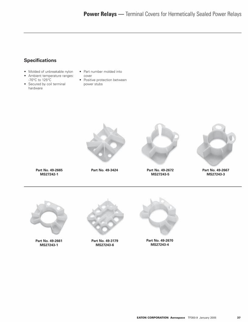
EATON CORPORATION Aerospace TF300-9 January 2005 37
Power Relays — Terminal Covers for Hermetically Sealed Power Relays
Specifications
• Molded of unbreakable nylon• Ambient temperature ranges: -70°C to 125°C• Secured by coil terminal hardware
• Part number molded into cover• Positive protection between power stubs
Part No. 49-2667
MS27243-3
Part No. 49-2672
MS27243-5
Part No. 49-3179
MS27243-6
Part No. 49-3424
Part No. 49-2661
MS27243-1
Part No. 49-2665
MS27242-1
Part No. 49-2670
MS27243-4
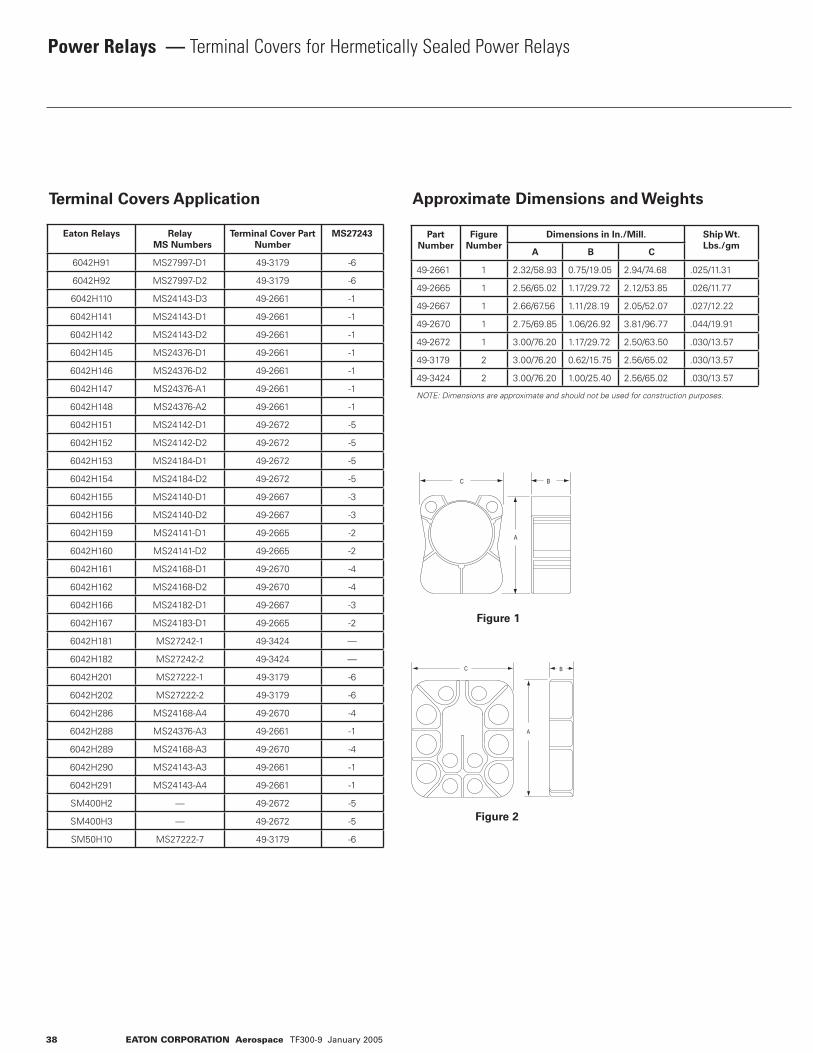
38 EATON CORPORATION Aerospace TF300-9 January 2005
Power Relays — Terminal Covers for Hermetically Sealed Power Relays
Terminal Covers Application Approximate Dimensions and Weights
Figure 1
Figure 2
Eaton Relays Relay
MS Numbers
Terminal Cover Part
Number
MS27243
6042H91 MS27997-D1 49-3179 -6
6042H92 MS27997-D2 49-3179 -6
6042H110 MS24143-D3 49-2661 -1
6042H141 MS24143-D1 49-2661 -1
6042H142 MS24143-D2 49-2661 -1
6042H145 MS24376-D1 49-2661 -1
6042H146 MS24376-D2 49-2661 -1
6042H147 MS24376-A1 49-2661 -1
6042H148 MS24376-A2 49-2661 -1
6042H151 MS24142-D1 49-2672 -5
6042H152 MS24142-D2 49-2672 -5
6042H153 MS24184-D1 49-2672 -5
6042H154 MS24184-D2 49-2672 -5
6042H155 MS24140-D1 49-2667 -3
6042H156 MS24140-D2 49-2667 -3
6042H159 MS24141-D1 49-2665 -2
6042H160 MS24141-D2 49-2665 -2
6042H161 MS24168-D1 49-2670 -4
6042H162 MS24168-D2 49-2670 -4
6042H166 MS24182-D1 49-2667 -3
6042H167 MS24183-D1 49-2665 -2
6042H181 MS27242-1 49-3424 —
6042H182 MS27242-2 49-3424 —
6042H201 MS27222-1 49-3179 -6
6042H202 MS27222-2 49-3179 -6
6042H286 MS24168-A4 49-2670 -4
6042H288 MS24376-A3 49-2661 -1
6042H289 MS24168-A3 49-2670 -4
6042H290 MS24143-A3 49-2661 -1
6042H291 MS24143-A4 49-2661 -1
SM400H2 — 49-2672 -5
SM400H3 — 49-2672 -5
SM50H10 MS27222-7 49-3179 -6
Part
Number
Figure
Number
Dimensions in In./Mill. Ship Wt.
Lbs./gmA B C
49-2661 1 2.32/58.93 0.75/19.05 2.94/74.68 .025/11.31
49-2665 1 2.56/65.02 1.17/29.72 2.12/53.85 .026/11.77
49-2667 1 2.66/67.56 1.11/28.19 2.05/52.07 .027/12.22
49-2670 1 2.75/69.85 1.06/26.92 3.81/96.77 .044/19.91
49-2672 1 3.00/76.20 1.17/29.72 2.50/63.50 .030/13.57
49-3179 2 3.00/76.20 0.62/15.75 2.56/65.02 .030/13.57
49-3424 2 3.00/76.20 1.00/25.40 2.56/65.02 .030/13.57
NOTE: Dimensions are approximate and should not be used for construction purposes.
C
A
B
C B
A
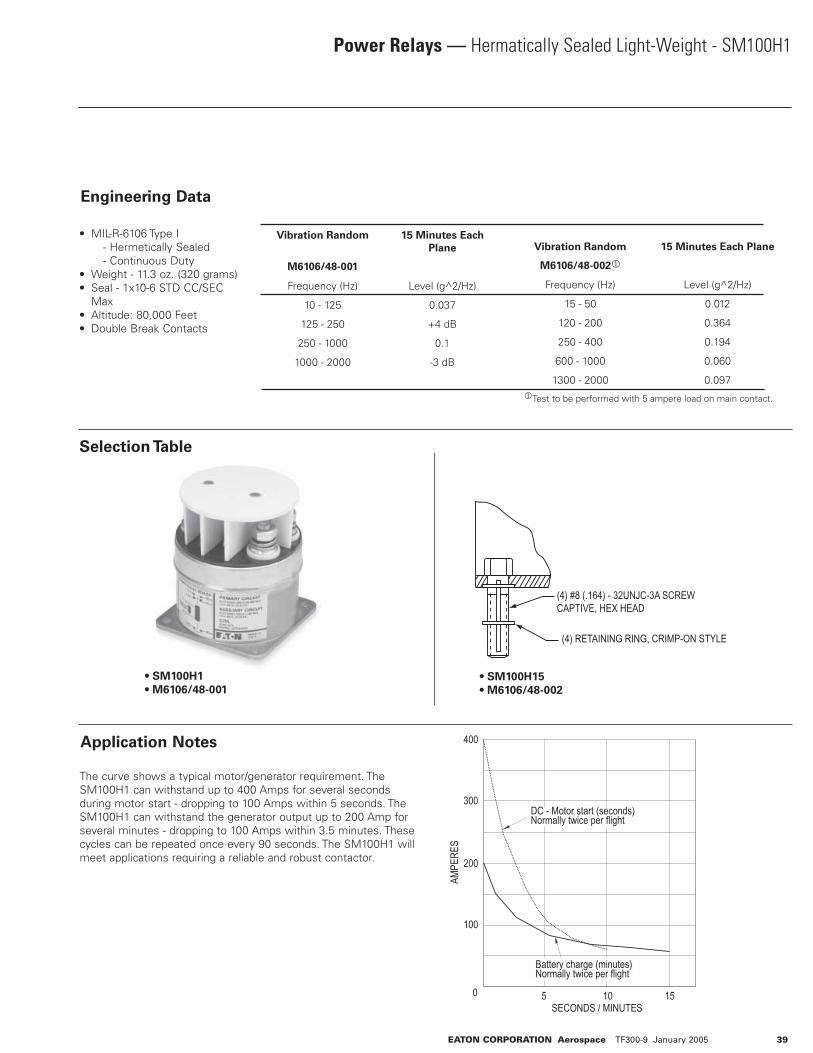
EATON CORPORATION Aerospace TF300-9 January 2005 39
Power Relays — Hermatically Sealed Light-Weight - SM100H1
Engineering Data
• MIL-R-6106 Type I - Hermetically Sealed - Continuous Duty• Weight - 11.3 oz. (320 grams)• Seal - 1x10⁻⁶ STD CC/SEC Max• Altitude: 80,000 Feet• Double Break Contacts
Selection Table
(4) #8 (.164) - 32UNJC-3A SCREWCAPTIVE, HEX HEAD
(4) RETAINING RING, CRIMP-ON STYLE
• SM100H1
• M6106/48-001
• SM100H15
• M6106/48-002
Application Notes
The curve shows a typical motor/generator requirement. The SM100H1 can withstand up to 400 Amps for several seconds during motor start - dropping to 100 Amps within 5 seconds. The SM100H1 can withstand the generator output up to 200 Amp for several minutes - dropping to 100 Amps within 3.5 minutes. These cycles can be repeated once every 90 seconds. The SM100H1 will meet applications requiring a reliable and robust contactor.
Vibration Random 15 Minutes Each
Plane
M6106/48-001
Frequency (Hz) Level (g^2/Hz)
10 - 125 0.037
125 - 250 +4 dB
250 - 1000 0.1
1000 - 2000 -3 dB
Vibration Random 15 Minutes Each Plane
M6106/48-0021
Frequency (Hz) Level (g^2/Hz)
15 - 50 0.012
120 - 200 0.364
250 - 400 0.194
600 - 1000 0.060
1300 - 2000 0.0971Test to be performed with 5 ampere load on main contact.
DC - Motor start (seconds)Normally twice per flight
400
300
AMPE
RES
200
100
5 10SECONDS / MINUTES
150
Battery charge (minutes)Normally twice per flight
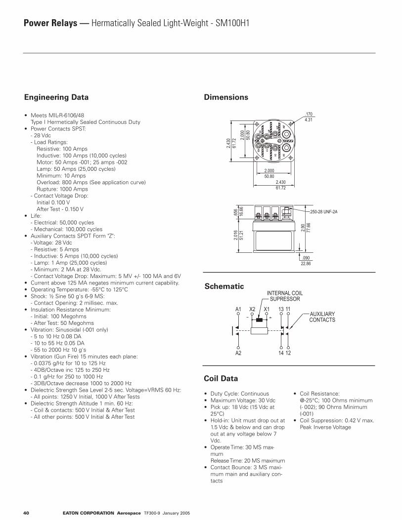
40 EATON CORPORATION Aerospace TF300-9 January 2005
Power Relays — Hermatically Sealed Light-Weight - SM100H1
Engineering Data
• Meets MIL-R-6106/48 Type I Hermetically Sealed Continuous Duty• Power Contacts SPST: - 28 Vdc - Load Ratings: Resistive: 100 Amps Inductive: 100 Amps (10,000 cycles) Motor: 50 Amps -001; 25 amps -002 Lamp: 50 Amps (25,000 cycles) Minimum: 10 Amps Overload: 800 Amps (See application curve) Rupture: 1000 Amps - Contact Voltage Drop: Initial 0.100 V After Test - 0.150 V• Life: - Electrical: 50,000 cycles - Mechanical: 100,000 cycles• Auxiliary Contacts SPDT Form "Z": - Voltage: 28 Vdc - Resistive: 5 Amps - Inductive: 5 Amps (10,000 cycles) - Lamp: 1 Amp (25,000 cycles) - Minimum: 2 MA at 28 Vdc. - Contact Voltage Drop: Maximum: 5 MV +/- 100 MA and 6V • Current above 125 MA negates minimum current capability.• Operating Temperature: -55°C to 125°C• Shock: ½ Sine 50 g's 6-9 MS: - Contact Opening: 2 millisec. max.• Insulation Resistance Minimum: - Initial: 100 Megohms - After Test: 50 Megohms• Vibration: Sinusoidal (-001 only) - 5 to 10 Hz 0.08 DA - 10 to 55 Hz 0.05 DA - 55 to 2000 Hz 10 g's• Vibration (Gun Fire) 15 minutes each plane: - 0.0375 g/Hz for 10 to 125 Hz - 4DB/Octave inc 125 to 250 Hz - 0.1 g/Hz for 250 to 1000 Hz - 3DB/Octave decrease 1000 to 2000 Hz• Dielectric Strength Sea Level 2-5 sec. Voltage=VRMS 60 Hz: - All points: 1250 V Initial, 1000 V After Tests• Dielectric Strength Altitude 1 min. 60 Hz: - Coil & contacts: 500 V Initial & After Test - All other points: 500 V Initial & After Test
• Duty Cycle: Continuous• Maximum Voltage: 30 Vdc• Pick up: 18 Vdc (15 Vdc at 25°C)• Hold-in: Unit must drop out at 1.5 Vdc & below and can drop out at any voltage below 7 Vdc.• Operate Time: 30 MS max- mum Release Time: 20 MS maximum• Contact Bounce: 3 MS maxi- mum main and auxiliary con- tacts
• Coil Resistance: @-25°C; 100 Ohms minimum (- 002); 90 Ohms Minimum (-001)• Coil Suppression: 0.42 V max. Peak Inverse Voltage
Dimensions
Schematic
Coil Data
.250-28 UNF-2A
.09022.86
2.90
77.66
.656
16.66
2.00050.80
.1704.31
2.000
50.80
2.43061.72
2.430
61.72
2.016
51.21
INTERNAL COILSUPRESSOR
AUXILIARYCONTACTS
X2 X1A1 13 11
A2 14 12

EATON CORPORATION Aerospace TF300-9 January 2005 41
Power Relays — Environmentally Sealed Lightweight - SM15 Series
Engineering Data
• Meets MIL-R-6106 Type IV• Weight: 10.5 ounces (284g)• Altitude: -Rated: 50,000 feet -Extended: 80,000 feet with encapsulated terminals• Ratings: -Voltage: 115/200 V, 400 Hz, 3Æ -Load Ratings: Resistive: 60 Amps Inductive: 60 Amps Motor: 40 Amps Minimum Current: 4 Amps Rupture: 400 Amps• Environmental Seal: MIL-STD- 202, METHOD 112 Test Condition C Procedure IV • Seal: 6 x 10⁻⁴ STD CC/SEC
• Economizer Coil: 30 Vdc -Inrush: 1.25 Amps (20 mil- liseconds max) -Steady State: 0.25 Amps
Typical Wiring Digrams
3 P.S.T. - N.C.
Auxiliary Contact
115/200 Vac 400 Hz 28 Vdc• Resistive 60 A. 20 A.• Inductive 60 A. 10 A.• Motor 40 A. ….• Minimum Current 4 A. ….• Rupture 400 A. ….• Contact Drop - Initial 0.150 V Max. …. - After Life Test 0.175 V. Max. ….• Contact Bounce 2 Milliseconds
1DC ratings are maximum overload capability. By wiring two poles in series, 28 Vdc rating can be increased to the same as the full AC ratings.
Options• AC operated coils• Encapsulated terminals• Internal coil suppression• Suitable for synchronized power supplied transfer
Power Contact Ratings (Continuous Duty)1
Selection Table
3 P.S.T. - N.C.
Auxiliary Contact
3 P.D.T. Without
Auxiliary Contact3 P.DT. With
Auxiliary Contact
3 P.S.T. N.O. Without
Auxiliary Contact With
Internal Coil Suppression
X1 (+)X2 (-)
A3
B3
C3
A2
B2
C2
X1 (+)X2 (-)
A3
B3
C3
A2
B2
C2
1211
X1 (+)X2 (-)
A3A1 A2
B3B1 B2
C3C1 C2
X1 (+)X2 (-)
A3A1 A2
B3B1 B2
C3C1 C2
1211
X1 (+)X2 (-)
A1 A2
B1 B2
C1 C2
13 13
Poles and
Throw-Circuit
Number of Auxiliary
Contacts 1 P.D.T.
Government Type
Number M6106
Catalog
Number
3 P.S.T.-N.O. —1
/10-001 /10-002
SM15AWD1SM15AXD1
3 P.S.T.-N.C. —1
/11-001 /11-002
SM15BWD1SM15BXD1
3 P.D.T. —1
/9-001 /9-002
SM15CWD1SM15CXD1
3 P.S.T.-N.O. — 10-005* SM15AWD3* Unit supplied with internal coil suppression .45V max. peak inverse voltage.
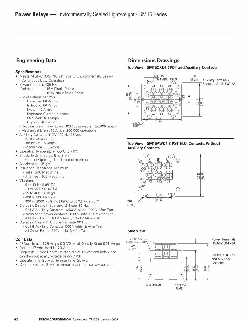
42 EATON CORPORATION Aerospace TF300-9 January 2005
Power Relays — Environmentally Sealed Lightweight - SM15 Series
Engineering Data
Specifications• Meets MIL-R-6106/9, /10, /11 Type IV Environmentally Sealed - Continuous Duty Operation• Power Contacts 400 Hz: - Voltage: 115 V Single Phase 115 V/ 200 V Three Phase - Load Ratings per Pole: Resistive: 60 Amps Inductive: 60 Amps Motor: 40 Amps Minimum Current: 4 Amps Overload: 320 Amps Rupture: 400 Amps - Electrical Life at Rated Loads: 100,000 operations (50,000 motor) - Mechanical Life at 15 Amps: 200,000 operations• Auxiliary Contacts 115 V 400 Hz/ 28 Vdc: - Resistive: 3 Amps - Inductive: 1.5 Amps - Mechanical: 0.5 Amps• Operating Temperature: -55°C to 71°C• Shock: ½ Sine, 25 g's 6 to 9 MS - Contact Opening: 1 millisecond maximum• Acceleration: 15 g's• Insulation Resistance Minimum - Initial: 200 Megohms - After Test: 100 Megohms• Vibration: - 5 to 10 Hz 0.08" DA - 10 to 55 Hz 0.06" DA - 55 to 400 Hz 10 g's - 400 to 800 Hz 8 g's - 800 to 2000 Hz 8 g's (-55°C to 25°C) 7 g's at 71°• Dielectric Strength Sea Level 2-5 sec. 60 Hz: - Coil & Auxiliary Contacts: 1250 V Initial, 1000 V After Test, Across open power contacts: 1250V Initial 625 V After Life. - All Other Points: 1800 V Initial, 1350 V After Test• Dielectric Strength Altitude 1 minute 60 Hz: - Coil & Auxiliary Contacts: 500 V Initial & After Test - All Other Points: 700V Initial & After Test
Coil Data• 28 Vdc: Inrush 1.25 Amps (20 MS Max); Steady State 0.25 Amps• Pick-up: 17 Vdc. Hold in: 7.0 Vdc Drop-out: 1.5 Vdc Unit must drop out at 1.5 Vdc and below and can drop out at any voltage below 7 Vdc.• Operate Time: 25 MS. Release Time: 25 MS• Contact Bounce: 2 MS maximum main and auxiliary contacts
Dimensions Drawings
Top View - SM15CXD1 3PDT and Auxiliary Contacts
Top View - SM15AWD1 3 PST N.O. Contacts. Without
Auxiliary Contacts
Side View
X2
X1
1.375(34.93)
A1 B1 C1
A2 B2 C2
.240 R.(6.096)
2.313
(58.7
5)
NAMEPLATE CIRCUITPLATE
1.890
(48.0
1)
2.125
(53.9
8)
.475(12.07)
UPPER ANDLOWER BARRIERS
2.500
(63.5
0)
3.032
(77.0
1)
A2
2.40(60.96)
.60(15.24)
A3 B3 C3
A1 B1 C1
13
1211
.240 R.(6.096)
1.06
(26.9
2)
.148(3.76)
DIA.4 MTG. HOLES
1.900
(48.2
6)
2.313
(50.7
5)
Auxiliary TerminalsScrew .112-40 UNC-2A
Power Terminals.190-32 UNF-2A
SM15CXDI 3PDT and Auxiliary Contacts
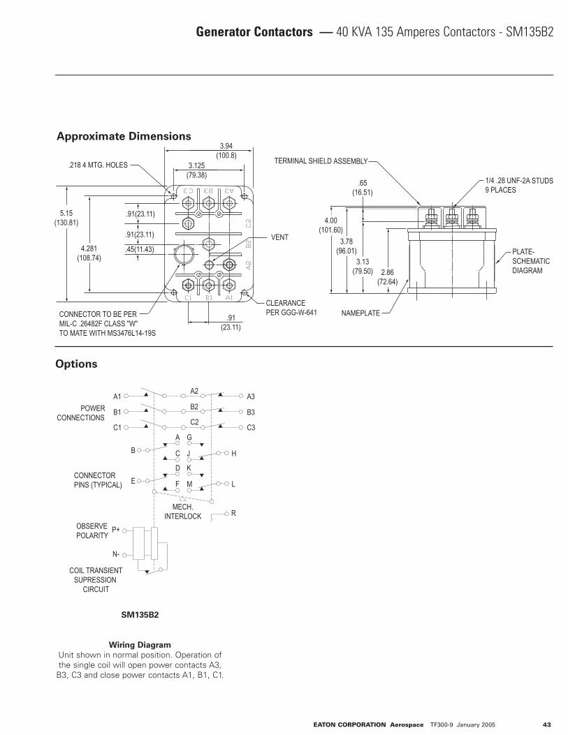
EATON CORPORATION Aerospace TF300-9 January 2005 43
Generator Contactors — 40 KVA 135 Amperes Contactors - SM135B2
3.94(100.8)
3.125(79.38)
VENT
CLEARANCEPER GGG-W-641
4.281(108.74)
.218 4 MTG. HOLES
.91(23.11)
.91(23.11)
.45(11.43)
CONNECTOR TO BE PERMIL-C .26482F CLASS "W" TO MATE WITH MS3476L14-19S
5.15(130.81)
.91(23.11)
4.00(101.60)
.65(16.51)
TERMINAL SHIELD ASSEMBLY
3.78(96.01)
3.13(79.50) 2.86
(72.64)
NAMEPLATE
1/4 .28 UNF-2A STUDS9 PLACES
PLATE-SCHEMATICDIAGRAM
OBSERVE POLARITY
MECH.INTERLOCK
CONNECTORPINS (TYPICAL)
COIL TRANSIENTSUPRESSION
CIRCUIT
POWERCONNECTIONS
A3
B3
C3
A1
B1
C1
A2
B2
C2
R
P+
N-
BA G
ED K
C J H
F M L
Options
Approximate Dimensions
SM135B2
Wiring Diagram
Unit shown in normal position. Operation of the single coil will open power contacts A3,
B3, C3 and close power contacts A1, B1, C1.
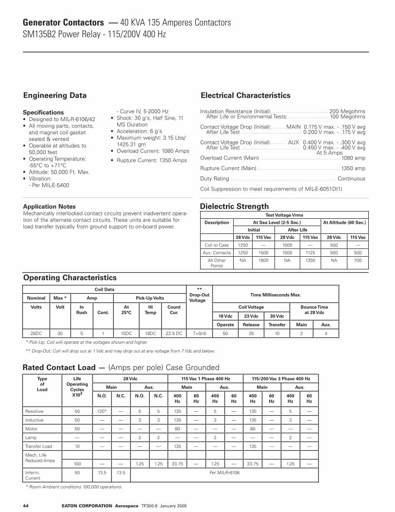
Generator Contactors — 40 KVA 135 Amperes ContactorsSM135B2 Power Relay - 115/200V 400 Hz
Electrical CharacteristicsEngineering Data
Specifications• Designed to MIL-R-6106/42• All moving parts, contacts, and magnet coil gasket sealed & vented• Operable at altitudes to 50,000 feet• Operating Temperature: -55°C to +71°C• Altitude: 50,000 Ft. Max.• Vibration: - Per MIL-E-5400
- Curve IV, 5-2000 Hz• Shock: 30 g's, Half Sine, 11 MS Duration• Acceleration: 6 g's• Maximum weight: 3.15 Lbs/ 1425.31 gm• Overload Current: 1080 Amps
• Rupture Current: 1350 Amps
Insulation Resistance (Initial): 200 Megohms After Life or Environmental Tests: 100 Megohms
Contact Voltage Drop (Initial): MAIN 0.175 V max. - .150 V avg After Life Test 0.200 V max. - .175 V avg
Contact Voltage Drop (Initial) AUX 0.400 V max. - .300 V avg After Life Test 0.450 V max. - .400 V avg At 5 AmpsOverload Current (Main) 1080 amp
Rupture Current (Main) 1350 amp
Duty Rating Continuous
Coil Suppression to meet requirements of MIL-E-6051D(1)
Application NotesMechanically interlocked contact circuits prevent inadvertent opera-tion of the alternate contact circuits. These units are suitable for load transfer typically from ground support to on-board power.
Dielectric Strength
44 EATON CORPORATION Aerospace TF300-9 January 2005
Test Voltage Vrms
Description At Sea Level (2-5 Sec.) At Altitude (60 Sec.)
Initial After Life
28 Vdc 115 Vac 28 Vdc 115 Vac 28 Vdc 115 Vac
Coil to Case 1250 — 1000 — 500 —
Aux. Contacts 1250 1500 1000 1125 500 500
All Other Points
NA 1800 NA 1350 NA 700
Operating Characteristics
Coil Data **
Drop-Out
Voltage
Time Milliseconds Max.Nominal Max * Amp Pick-Up Volts
Volts Volt In
Rush
Cont.
At
25°C
Hi
Temp
Count
Cur.
Coil Voltage Bounce Time
at 28 Vdc18 Vdc 23 Vdc 30 Vdc
Operate Release Transfer Main Aux.
28DC 30 5 1 15DC 18DC 22.5 DC 7+0/-6 50 35 10 2 4
* Pick-Up: Coil will operate at the voltages shown and higher.
** Drop-Out: Coil will drop out at 1 Vdc and may drop out at any voltage from 7 Vdc and below.
Rated Contact Load — (Amps per pole) Case GroundedType
of
Load
Life
Operating
Cycles
X103
28 Vdc 115 Vac 1 Phase 400 Hz 115/200 Vac 3 Phase 400 Hz
Main Aux. Main Aux. Main Aux.
N.O. N.C. N.O. N.C. 400
Hz
60
Hz
400
Hz
60
Hz
400
Hz
60
Hz
400
Hz
60
Hz
Resistive 50 120* — 5 5 135 — 5 — 135 — 5 —
Inductive 50 — — 3 3 135 — 3 — 135 — 3 —
Motor 50 — — — — 80 — — — 80 — — —
Lamp — — — 2 2 — — 2 — — — 2 —
Transfer Load 10 — — — — 135 — — — 135 — — —
Mech. Life Reduced Amps
100 — — 1.25 1.25 33.75 — 1.25 — 33.75 — 1.25 —
Interm. Current
50 13.5 13.5 Per MIL-R-6106
* Room Ambient conditions 100,000 operations.
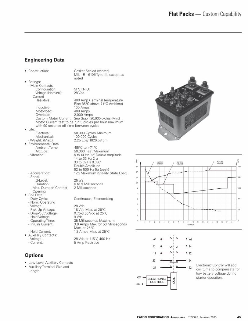
EATON CORPORATION Aerospace TF300-9 January 2005 45
Flat Packs — Custom Capability
Engineering Data
• Construction: Gasket Sealed (vented) - MIL - R - 6106 Type III, except as noted• Ratings: - Main Contacts Configuration: SPST N.O. Voltage (Nominal): 28 Vdc Current Resistive: 400 Amp (Terminal Temperature Rise 85°C above 71°C Ambient) Inductive: 100 Amps Motorload: 400 Amps Overload: 2,000 Amps Custom Motor Current: See Graph 20,000 cycles (Min.) Motor Current test to be run 5 cycles per hour maximum with 90 seconds off time between cycles• Life: Electrical: 50,000 Cycles Minimum Mechanical: 100,000 Cycles - Weight: (Max.): 2.25 Lbs/ 1020.58 gm• Environmental Data Ambient Temp: -55°C to +71°C Altitude: 50,000 Feet Maximum - Vibration: 5 to 14 Hz 0.2" Double Amplitude 14 to 33 Hz 2 g 33 to 52 Hz 0.036" Double Amplitude 52 to 500 Hz 5g (peak) - Acceleration: 12g Maximum (Steady State Load) - Shock: G-Level: 25 g's Duration: 6 to 9 Milliseconds - Max. Duration Contact 2 Milliseconds Opening • Coil Data: - Duty Cycle: Continuous, Economizing - Nom. Operating - Voltage: 28 Vdc - Pick-Up Voltage: 18 Vdc Max. at 25°C - Drop-Out Voltage: 0.75-3.50 Vdc at 25°C - Hold Voltage: 9 Vdc - Operating Time: 35 Milliseconds Maximum - Inrush Current: 3.0 Amps Max for 50 Milliseconds Max. at 25°C - Hold Current: 1.2 Amps Max. at 25°C• Auxiliary Contacts: - Voltage: 28 Vdc or 115 V, 400 Hz - Current: 5 Amp Resistive
• Low Level Auxiliary Contacts• Auxiliary Terminal Size and Length
Options
Electronic Control will add coil turns to compensate for low battery voltage during starter operation.
STARTERVOLTAGE
STARTERCURRENT
BATTERYVOLTAGE
27
24
21
18
12
9
6
3
15
0 0
30
SECONDS
V0LT
S
AMPS
2000
1600
1200
800
400
1817161514131211109876543210
+X1
-X2
ELECTRONIC CONTROL C
OIL
A1 A2
1211
13 14
2221
23 24
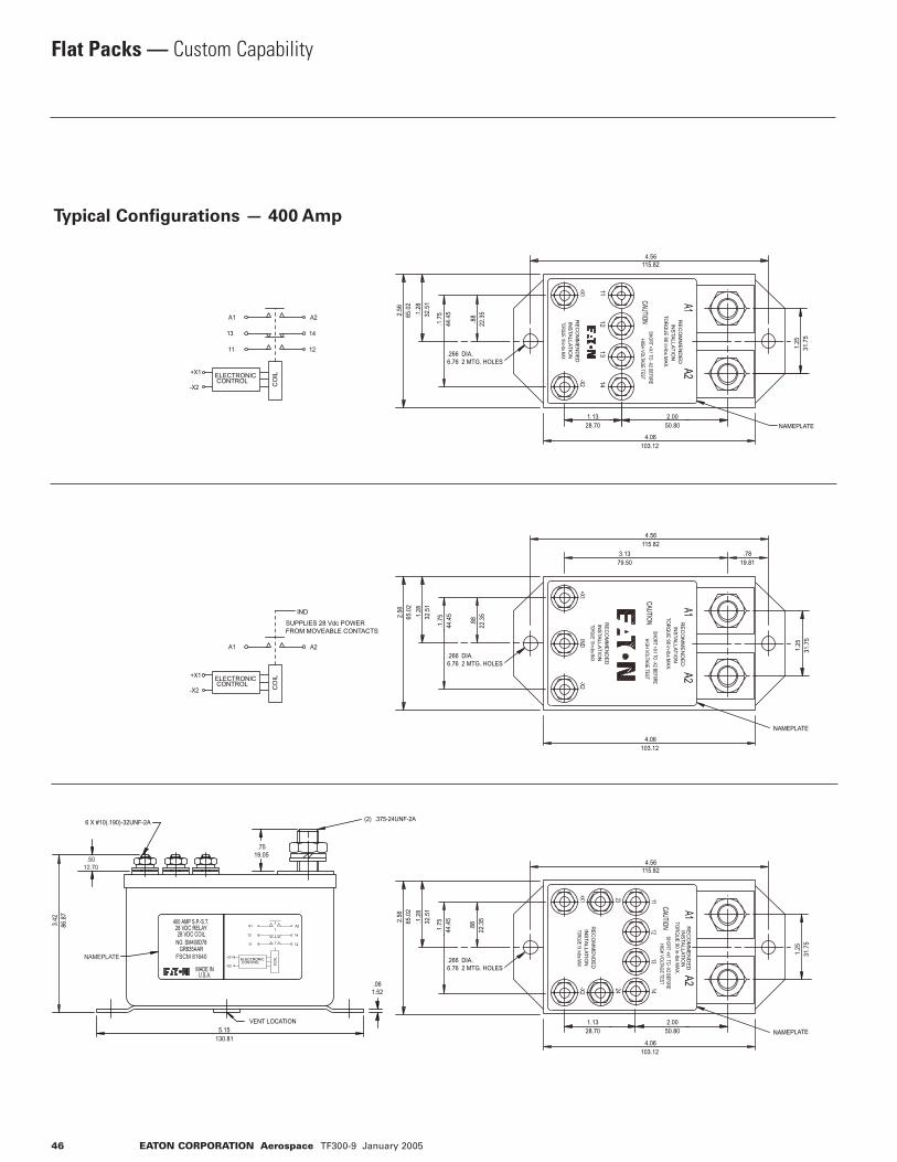
46 EATON CORPORATION Aerospace TF300-9 January 2005
Flat Packs — Custom Capability
Typical Configurations — 400 Amp
1211
+X1
-X2
ELECTRONIC CONTROL C
OIL
A1 A2
13 14
A2A1
1413
1211
-X2+X1
INSTALLATIO
NR
EC
OM
ME
ND
ED
HIGH VOLTAGE TESTSHORT +X1 TO -X2 BEF0RE
CAUTIONINSTALLATIO
NR
ECO
MM
END
ED
TORQUE 19 in-lbs MAX
TORQ
UE 90 in-lbs MAX.
NAMEPLATE
4.56115.82
4.06103.12
.2666.76
DIA.2 MTG. HOLES
.88
22.3
5
.1.7
544
.45.1
.28
32.5
1
2.56
65.0
2
1.25
31.7
5
2.0050.80
1.1328.70
A2A1
-X2IND
+X1
INSTALLATIO
NR
EC
OM
ME
ND
ED
HIGH VOLTAGE TESTSHORT +X1 TO -X2 BEF0RE
CAUTIONINSTALLATIO
NR
ECO
MM
END
ED
TORQUE 19 in-lbs MAX
TORQ
UE 90 in-lbs MAX.
NAMEPLATE
4.56115.82
3.1379.50
.7819.81
4.06103.12
1.25
31.7
5
A2A1
+X1-X2
2324
1112
1314
INSTALLATIO
NR
EC
OM
ME
ND
ED
HIGH VOLTAGE TESTSHORT +X1 TO -X2 BEF0RE
CAUTIONINSTALLATIO
NR
ECO
MM
END
ED
TORQUE 19 in-lbs MAX
TORQ
UE 90 in-lbs MAX.
NAMEPLATE
4.56115.82
4.06103.12
1.25
31.7
5
2.0050.80
1.1328.70
3.42
86.8
7
NAMEPLATE
400 AMP S.P.-S.T.28 VDC RELAY28 VDC COIL
NO. SM400D78
FSCM 81640
MADE INU.S.A.
VENT LOCATION5.15
130.81
.5012.70
6 X #10(.190)-32UNF-2A
GR835AAR
.061.52
.7519.05
(2) .375-24UNF-2A
1211
+X1
-X2
ELECTRONIC CONTROL C
OIL
A1 A2
13 14
+X1
-X2
ELECTRONIC
INDSUPPLIES 28 Vdc POWERFROM MOVEABLE CONTACTS
CONTROL CO
IL
A1 A2.2666.76
DIA.2 MTG. HOLES
.88
22.3
5
.1.7
544
.45.1.2
832
.51
2.56
65.0
2
.2666.76
DIA.2 MTG. HOLES
.88
22.3
5
.1.7
544
.45.1.2
832
.51
2.56
65.0
2
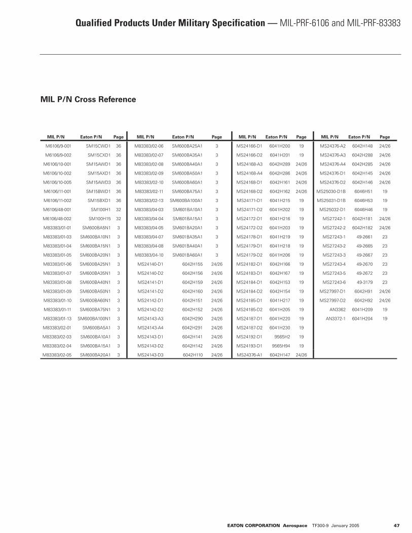
Qualified Products Under Military Specification — MIL-PRF-6106 and MIL-PRF-83383
MIL P/N Cross Reference
EATON CORPORATION Aerospace TF300-9 January 2005 47
MIL P/N Eaton P/N Page MIL P/N Eaton P/N Page MIL P/N Eaton P/N Page MIL P/N Eaton P/N Page
M6106/9-001 SM15CWD1 36 M83383/02-06 SM600BA25A1 3 MS24166-D1 6041H200 19 MS24376-A2 6042H148 24/26
M6106/9-002 SM15CXD1 36 M83383/02-07 SM600BA35A1 3 MS24166-D2 6041H201 19 MS24376-A3 6042H288 24/26
M6106/10-001 SM15AWD1 36 M83383/02-08 SM600BA40A1 3 MS24168-A3 6042H289 24/26 MS24376-A4 6042H285 24/26
M6106/10-002 SM15AXD1 36 M83383/02-09 SM600BA50A1 3 MS24168-A4 6042H286 24/26 MS24376-D1 6042H145 24/26
M6106/10-005 SM15AWD3 36 M83383/02-10 SM600BA60A1 3 MS24168-D1 6042H161 24/26 MS24376-D2 6042H146 24/26
M6106/11-001 SM15BWD1 36 M83383/02-11 SM600BA75A1 3 MS24168-D2 6042H162 24/26 MS25030-D1B 6046H51 19
M6106/11-002 SM15BXD1 36 M83383/02-13 SM600BA100A1 3 MS24171-D1 6041H215 19 MS25031-D1B 6046H53 19
M6106/48-001 SM100H1 32 M83383/04-03 SM601BA10A1 3 MS24171-D2 6041H202 19 MS25032-D1 6046H46 19
M6106/48-002 SM100H15 32 M83383/04-04 SM601BA15A1 3 MS24172-D1 6041H216 19 MS27242-1 6042H181 24/26
M83383/01-01 SM600BA5N1 3 M83383/04-05 SM601BA20A1 3 MS24172-D2 6041H203 19 MS27242-2 6042H182 24/26
M83383/01-03 SM600BA10N1 3 M83383/04-07 SM601BA35A1 3 MS24178-D1 6041H219 19 MS27243-1 49-2661 23
M83383/01-04 SM600BA15N1 3 M83383/04-08 SM601BA40A1 3 MS24179-D1 6041H218 19 MS27243-2 49-2665 23
M83383/01-05 SM600BA20N1 3 M83383/04-10 SM601BA60A1 3 MS24179-D2 6041H206 19 MS27243-3 49-2667 23
M83383/01-06 SM600BA25N1 3 MS24140-D1 6042H155 24/26 MS24182-D1 6042H166 19 MS27243-4 49-2670 23
M83383/01-07 SM600BA35N1 3 MS24140-D2 6042H156 24/26 MS24183-D1 6042H167 19 MS27243-5 49-2672 23
M83383/01-08 SM600BA40N1 3 MS24141-D1 6042H159 24/26 MS24184-D1 6042H153 19 MS27243-6 49-3179 23
M83383/01-09 SM600BA50N1 3 MS24141-D2 6042H160 24/26 MS24184-D2 6042H154 19 MS27997-D1 6042H91 24/26
M83383/01-10 SM600BA60N1 3 MS24142-D1 6042H151 24/26 MS24185-D1 6041H217 19 MS27997-D2 6042H92 24/26
M83383/01-11 SM600BA75N1 3 MS24142-D2 6042H152 24/26 MS24185-D2 6041H205 19 AN3362 6041H209 19
M83383/01-13 SM600BA100N1 3 MS24143-A3 6042H290 24/26 MS24187-D1 6041H220 19 AN3372-1 6041H204 19
M83383/02-01 SM600BA5A1 3 MS24143-A4 6042H291 24/26 MS24187-D2 6041H230 19
M83383/02-03 SM600BA10A1 3 MS24143-D1 6042H141 24/26 MS24192-D1 9565H2 19
M83383/02-04 SM600BA15A1 3 MS24143-D2 6042H142 24/26 MS24193-D1 9565H94 19
M83383/02-05 SM600BA20A1 3 MS24143-D3 6042H110 24/26 MS24376-A1 6042H147 24/26


