ELECTRIC DC MOTORSNY Robotics Group Meet-up
April 25, 2013
Roger Mosciatti
Foodinie
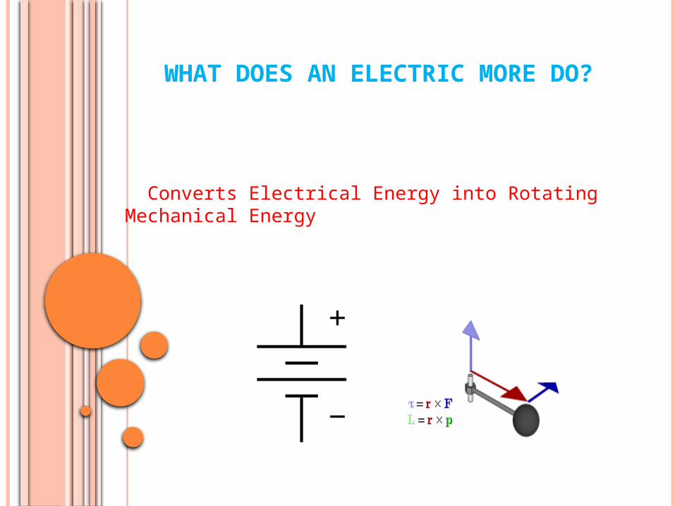
WHAT DOES AN ELECTRIC MORE DO?
Converts Electrical Energy into Rotating Mechanical Energy

MAGNETIC ATTRACTION AND REPULSION
N N N S F F F S S N Motion Motion
How to reverse polarity? Make one an electromagnet!
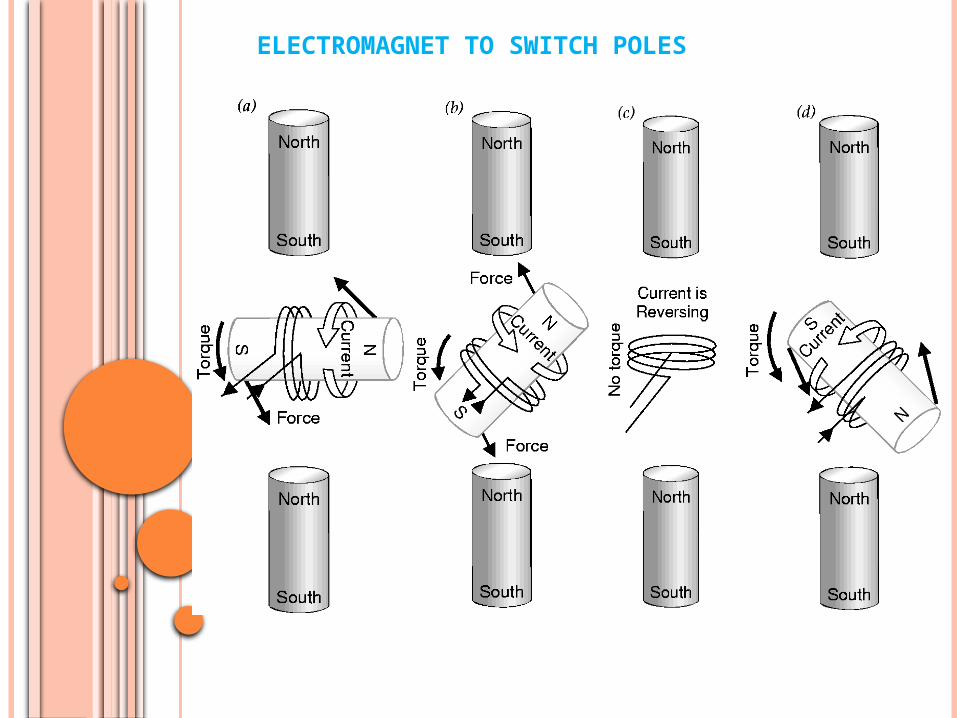
ELECTROMAGNET TO SWITCH POLES
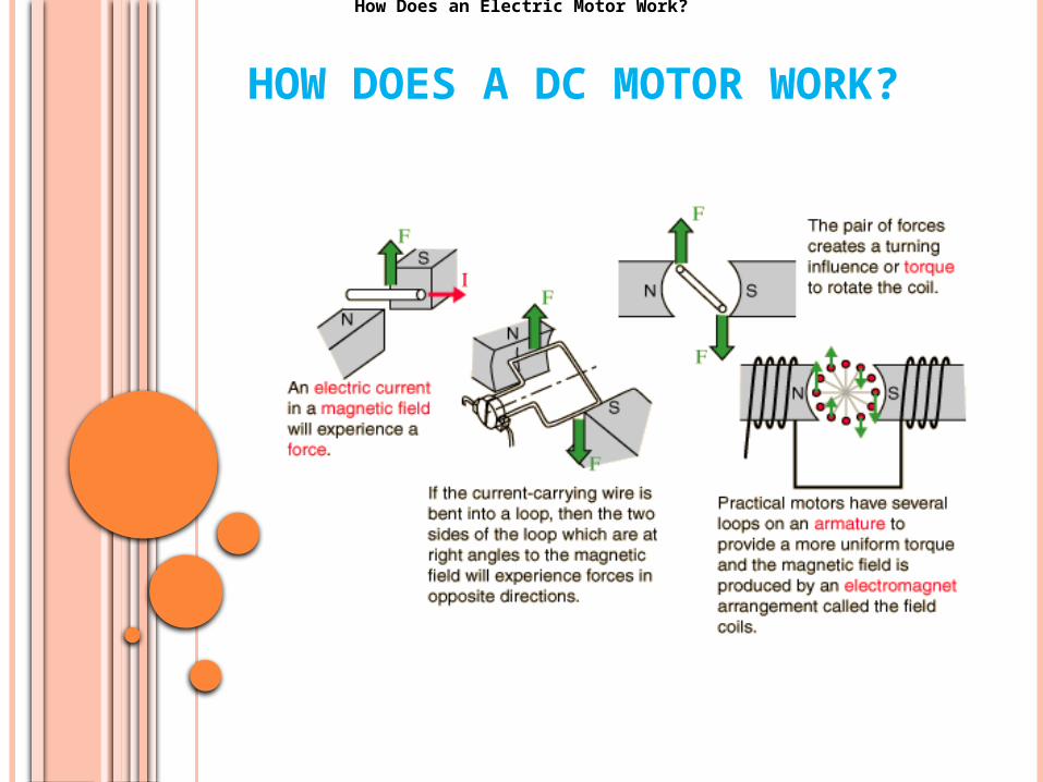
HOW DOES A DC MOTOR WORK?
How Does an Electric Motor Work?

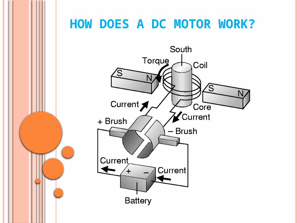
HOW DOES A DC MOTOR WORK?
DC Motor OperationThis is an active graphic. Click on bold type for further illustration.
HOW DOES A DC MOTOR WORK?
HOW DOES A DC MOTOR WORK?
Motor.exe
HOW DOES A DC MOTOR WORK?
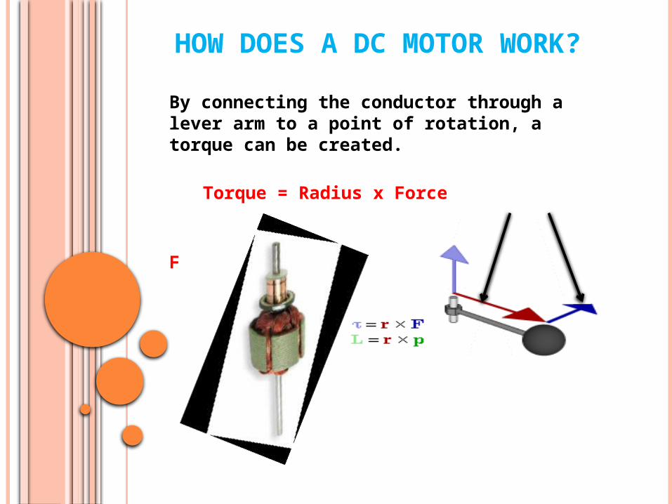
By connecting the conductor through a lever arm to a point of rotation, a torque can be created.
Torque = Radius x Force
R F
f
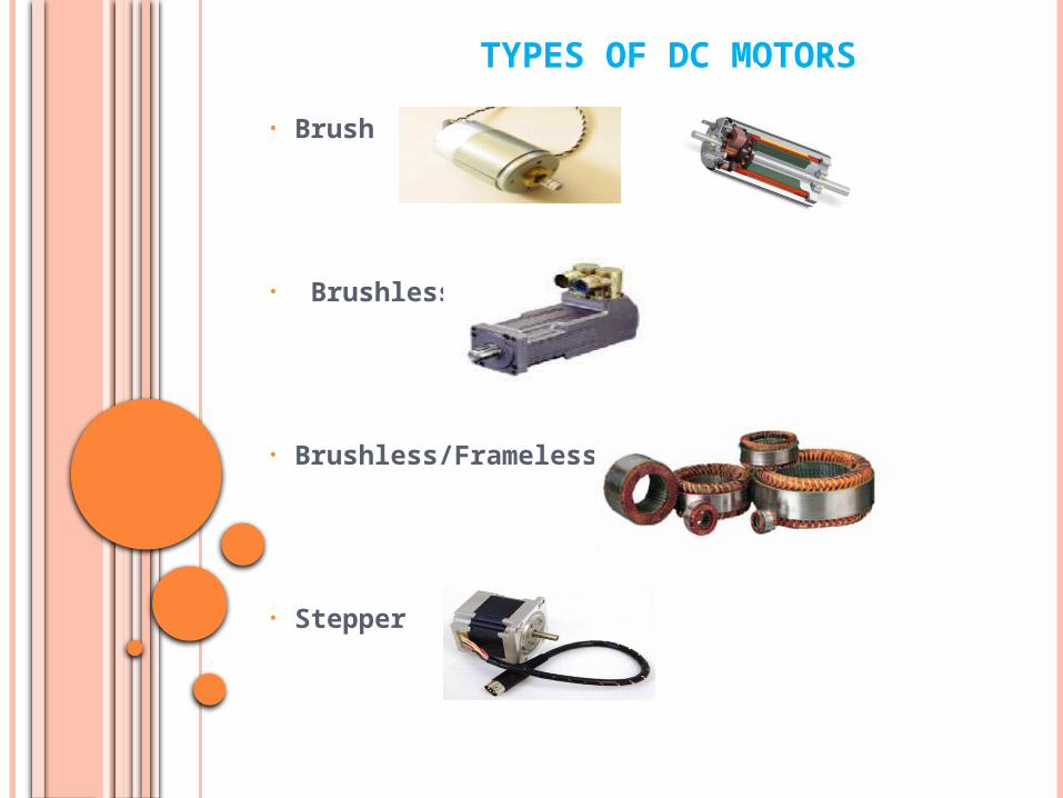
TYPES OF DC MOTORS
• Brush
• Brushless
• Brushless/Frameless
• Stepper
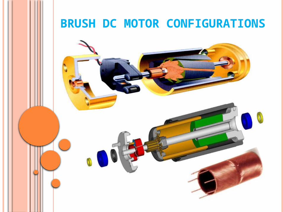
BRUSH DC MOTOR CONFIGURATIONS
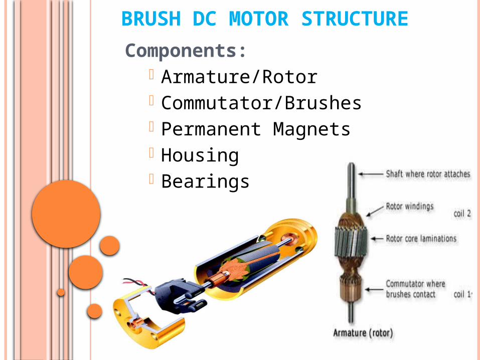
BRUSH DC MOTOR STRUCTURE
Components:• Armature/Rotor• Commutator/Brushes• Permanent Magnets• Housing• Bearings
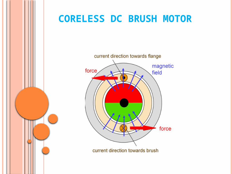
CORELESS DC BRUSH MOTOR
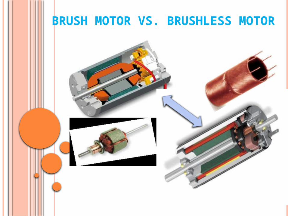
BRUSH MOTOR VS. BRUSHLESS MOTOR

Brushless Coreless DC Motor
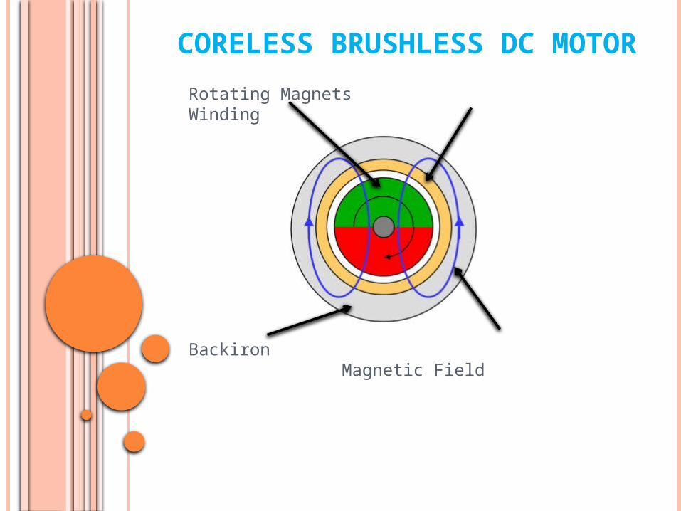
CORELESS BRUSHLESS DC MOTOR
Rotating Magnets Winding
Backiron Magnetic Field

INDUSTRIAL GRADE BRUSHLESS
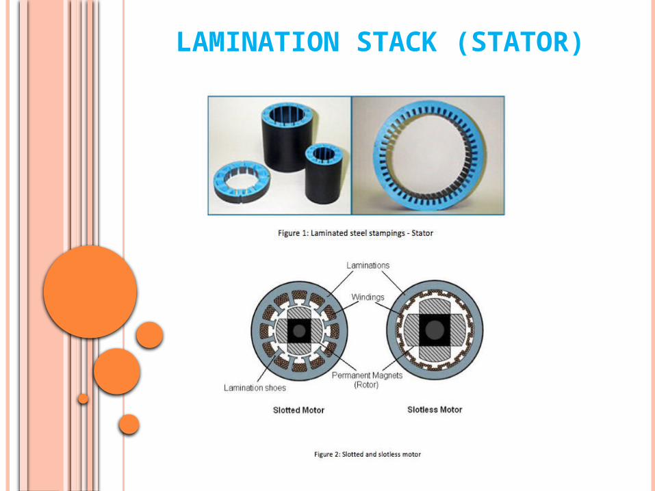
LAMINATION STACK (STATOR)

BRUSHLESS DC MOTOR STRUCTUREComponents:
• Electronic Commutator• Rotor/Magnets• Stator/Windings• Housing• Bearings
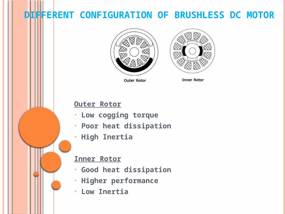
DIFFERENT CONFIGURATION OF BRUSHLESS DC MOTOR
Outer Rotor• Low cogging torque• Poor heat dissipation• High Inertia
Inner Rotor• Good heat dissipation• Higher performance• Low Inertia
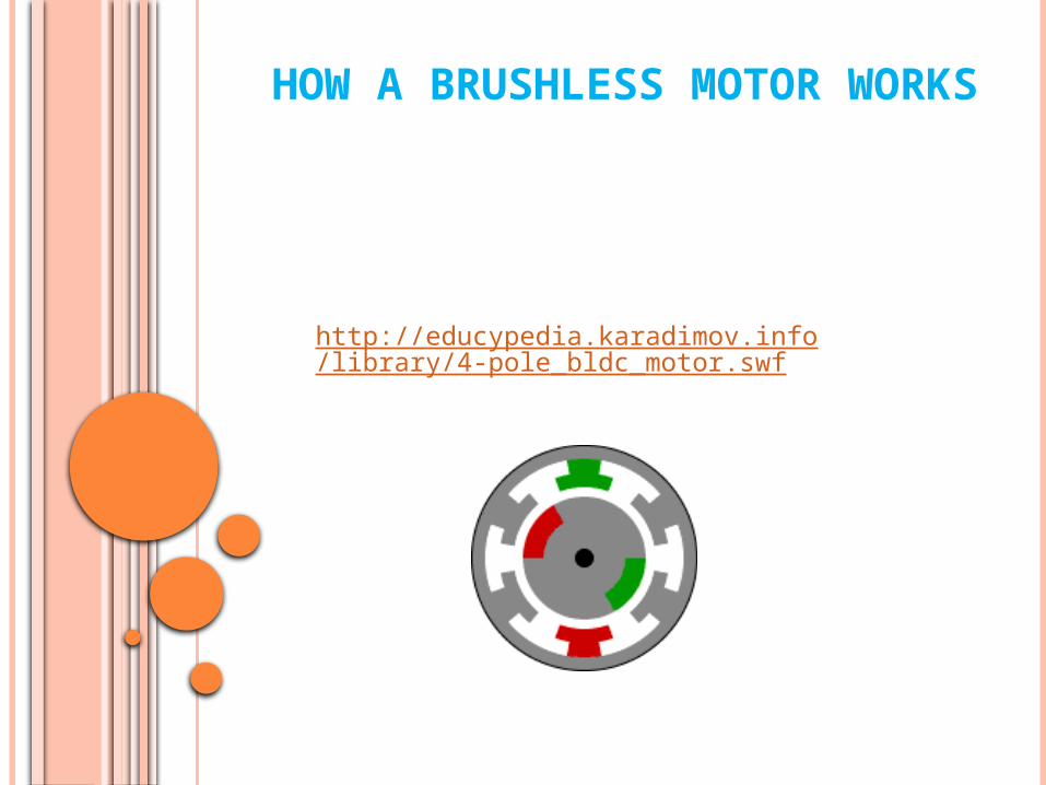
HOW A BRUSHLESS MOTOR WORKS
http://educypedia.karadimov.info/library/4-pole_bldc_motor.swf
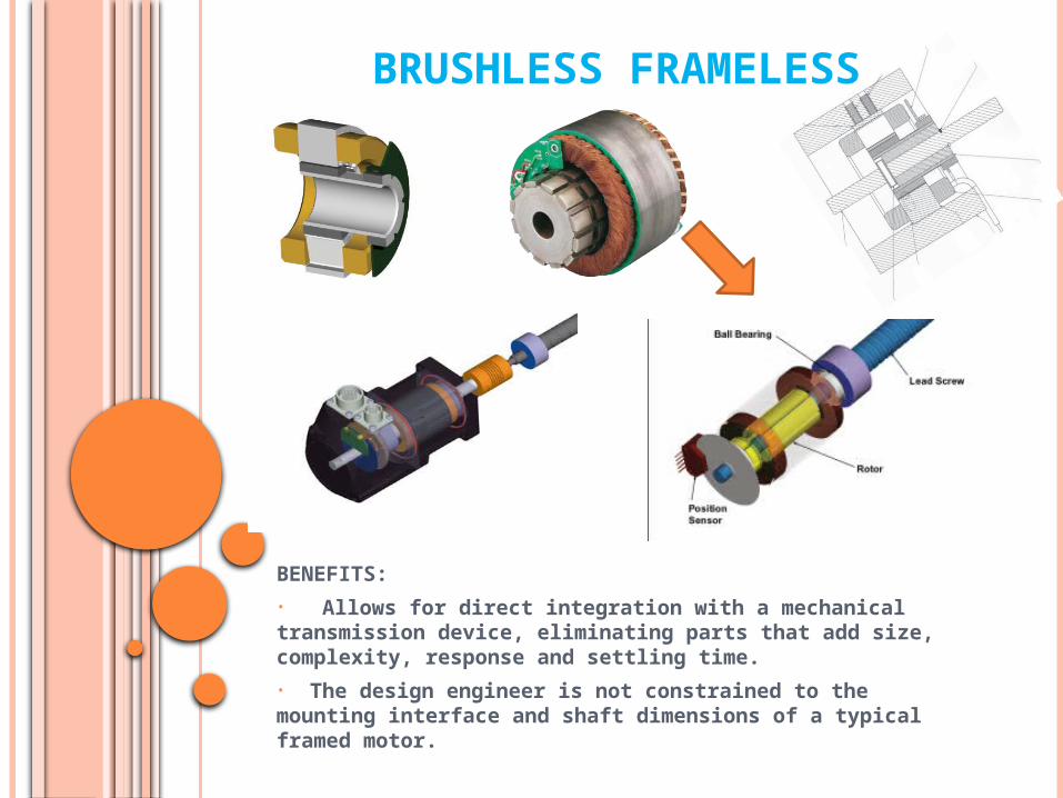
BRUSHLESS FRAMELESS
BENEFITS:
• Allows for direct integration with a mechanical transmission device, eliminating parts that add size, complexity, response and settling time.
• The design engineer is not constrained to the mounting interface and shaft dimensions of a typical framed motor.
BRUSH VS. BRUSHLESS
ADVANTAGES of BRUSH MOTOR• Two wire control• Replaceable brushes for extended life• Low cost of construction• Simple and inexpensive controls
DISADVANTAGES • Periodic maintenance is required for brush wear• At higher speeds, brush friction increases, thus reducing useful torque• Poor heat dissipation due to internal rotor construction• Higher rotor inertia which limits the dynamic characteristics• Lower speed range due to mechanical limitations on the brushes• Brush Arcing will generate noise causing EMI
BRUSH VS. BRUSHLESS
ADVANTAGES of BRUSHLESS MOTOR• Electronic commutation based on Hall position sensors• Less required maintenance due to absence of brushes• High efficiency, no voltage drop across brushes• Higher speed range - no mechanical limitation imposed by brushes/commutator• Essentially no (EMI) electric noise generation • The windings in the stator laminations assembly are connected to the housing yielding excellent heat dissipation resulting in:
• Higher output power/frame size. • Smaller size than brush motors for same power.
DISADVANTAGES • Higher cost of construction• Control is complex and expensive

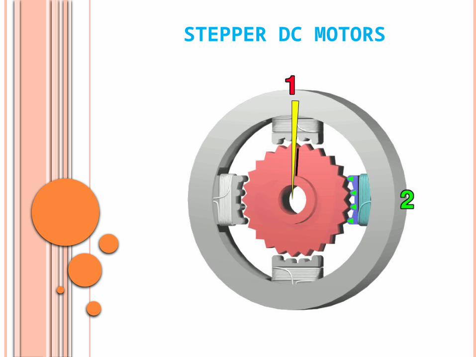
STEPPER DC MOTOR
What is it?
Is a brushless motor that divides a full rotation into a number of equal steps. The motor’s position can be then commanded to move and hold at one of these steps without feedback sensor, open loop, as long as the motor is properly sized for the application.
How does it work?
Brush or brushless motors rotate continuously when voltage is applied. Stepper motors have multiple “toothed” electromagnets arranged around a central shaped piece of iron or permanent magnet. To make run, first, one electromagnet is given power, which makes the gear's teeth magnetically attracted to the electromagnet’s teeth. When the gear’s teeth are aligned to the first electromagnet , they are slightly offset from the next electromagnet. Then the next electromagnet is turned on and the process starts again.

HOW A STEPPER DC MOTORS WORKS


STEPPER VS. BRUSH, BRUSHLESS MOTOR
• Stepper smaller power to weight size ratio• Stepper are usually 70% efficient where brush or brushless are 80% to 90% efficient• Stepper usually have a low resolution .9 to 1.8 deg. That is 400 steps/ rev. Where the other can go to 4,096 steps/rev• Stepper motors may stall and skip steps if the motor is not powerful enough by misapplying it.• Stepper motors draw excess current regardless of load. The excess power is dissipated as heat.• Stepper motors produce a slight hum due to the control process.• Stepper motors vibrate slightly and have some resonance issues because of how the stepper motor operates.
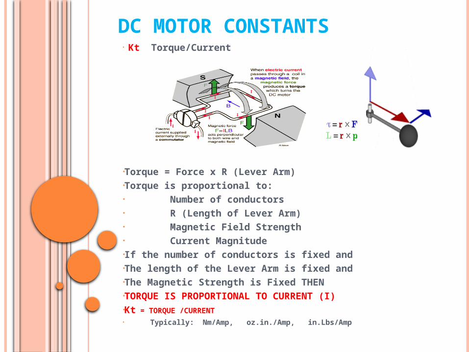
DC MOTOR CONSTANTS• Kt Torque/Current
•Torque = Force x R (Lever Arm)•Torque is proportional to:• Number of conductors• R (Length of Lever Arm)• Magnetic Field Strength• Current Magnitude•If the number of conductors is fixed and •The length of the Lever Arm is fixed and •The Magnetic Strength is Fixed THEN•TORQUE IS PROPORTIONAL TO CURRENT (I)•Kt = TORQUE /CURRENT
• Typically: Nm/Amp, oz.in./Amp, in.Lbs/Amp
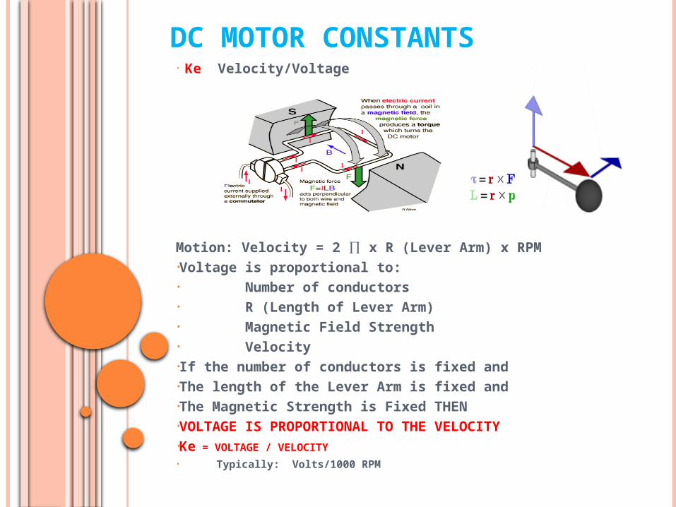
DC MOTOR CONSTANTS• Ke Velocity/Voltage
Motion: Velocity = 2 ∏ x R (Lever Arm) x RPM•Voltage is proportional to:• Number of conductors• R (Length of Lever Arm)• Magnetic Field Strength• Velocity•If the number of conductors is fixed and •The length of the Lever Arm is fixed and •The Magnetic Strength is Fixed THEN•VOLTAGE IS PROPORTIONAL TO THE VELOCITY•Ke = VOLTAGE / VELOCITY
• Typically: Volts/1000 RPM
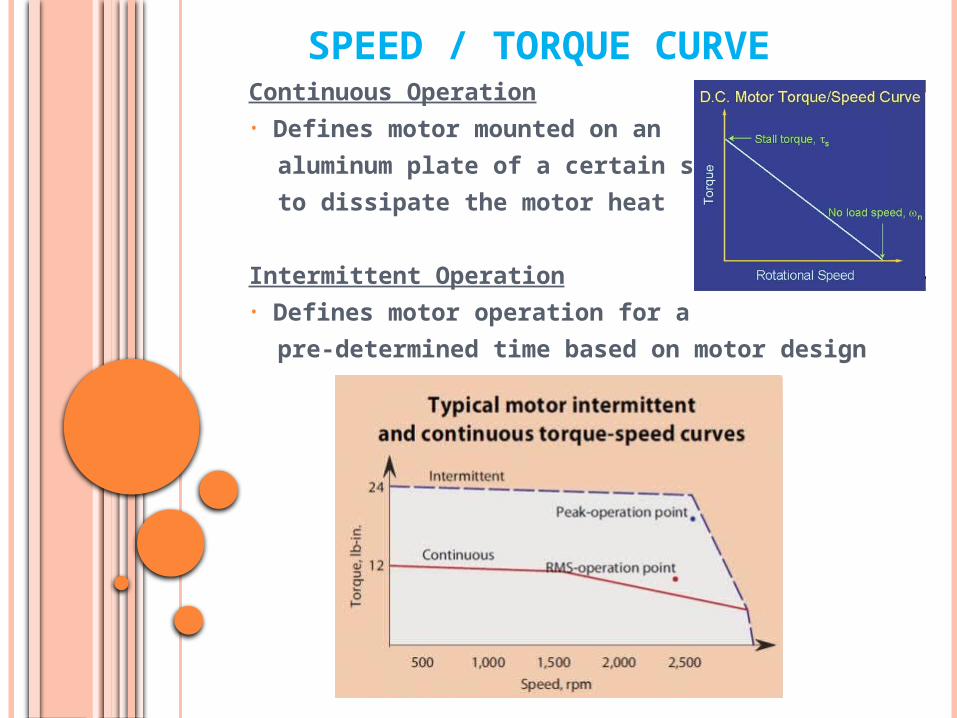
SPEED / TORQUE CURVEContinuous Operation• Defines motor mounted on an
aluminum plate of a certain size
to dissipate the motor heat
Intermittent Operation• Defines motor operation for a
pre-determined time based on motor design

FEEDBACK SENSORS• Optical Encoder
Up to 5,000 PPR
•Absolute Encoder
Optical, Magnetic, Capacitive
16 to 20 bit resolution
(1,048,576 PPR)
• Resolver
14 bit resolution
(16,384 PPR)

TORQUE MULTIPLIER
Why use a gear box?• A gearbox uses mechanical advantage to increase output torque and reduce RPM• Improves the Inertia matching. Should the load Inertia significantly exceeds that of the motor it causes excessive overshoot and increase settling times. It greatly enhances system responsive time. • Reduces system cost by the need of smaller motors and drives.
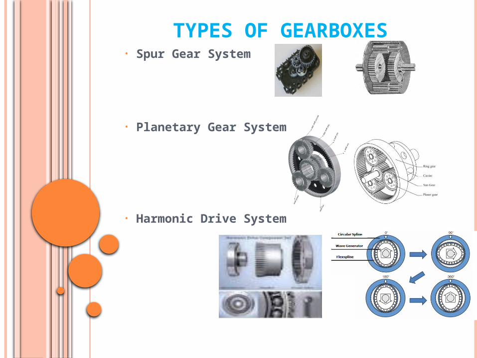
TYPES OF GEARBOXES• Spur Gear System
• Planetary Gear System
• Harmonic Drive System
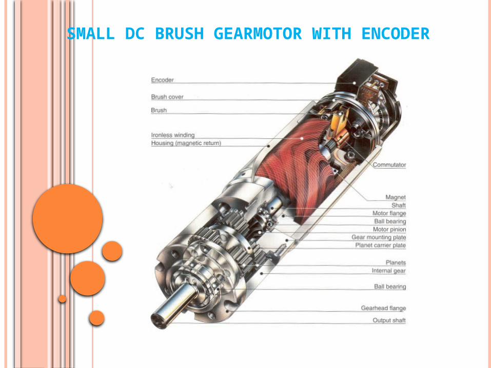
SMALL DC BRUSH GEARMOTOR WITH ENCODER

INDUSTRIAL DC BRUSHLESS GEARMOTOR

PWM MOTOR DRIVEP = Pulse
W = Width
M = Modulation
How do they work?
Supplies the motor with high frequency power pulses (15 KHz to 35 KHz) whose width is proportional to the required power level as determined by the input command.
Since the power transistors are either completely “ON” or “OFF”, they experience dissipation only while they are switching or they are “ON” with a very low voltage drop, resulting in an efficiency of 85% to 95%
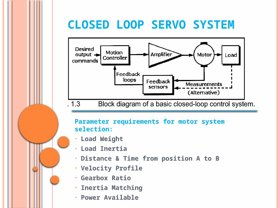
CLOSED LOOP SERVO SYSTEM
Parameter requirements for motor system selection:• Load Weight• Load Inertia• Distance & Time from position A to B• Velocity Profile • Gearbox Ratio • Inertia Matching • Power Available

THANK YOU
Questions?


![[Skolkovo Robotics 2015 Day 1] Зигель Х. Communicating Robotics | Siegel H. Communicating Robotics](https://cdn.vdocuments.mx/doc/165x107/55a657b21a28ab56308b475a/skolkovo-robotics-2015-day-1-communicating-robotics-siegel-h-communicating-robotics.jpg)
