
Electric cylinders EPCO, with spindle drive

Subject to change – 2016/102 � Internet: www.festo.com/catalogue/...
Electric cylinders EPCO, with spindle driveKey features
At a glance
General Properties Range of applications
The electric cylinder EPCO is a
mechanical linear drive with piston
rod and permanently attached motor.
The driving component consists of an
electrically actuated spindle that con
verts the rotary motion of the motor
into a linear motion of the piston rod.
� With recirculating ball spindle
� Optionally with female thread
� Optionally with holding brake
� Degree of protection IP40
� Compact dimensions
� Extensive mounting accessories for
various installation situations
� Suitable for simple applications in
factory automation that in the past
were mostly carried out using
pneumatic solutions
Optimised Motion Series (OMS)
A package that makes positioning
easier than ever before.
The Optimised Motion Series is as
easy to handle as a pneumatic
cylinder, but with the functionality of
an electric drive.
Simple to select Ordering and logistics Quick to configure
� Easy sizing and selection using
cycle time charts
� No specialist knowledge of electric
drive technology required
� All the part components required
with a single part number
� Motors mounted on electric
cylinders
� Parameterisation and commission
ing via web server/browser
� Parameterise up to 7 freely
definable positions directly on the
PC
For simple positioning tasks
Electric cylinder EPCO Controller CMMO
� 38
2016/10 – Subject to change 3� Internet: www.festo.com/catalogue/...
Electric cylinders EPCO, with spindle driveKey features
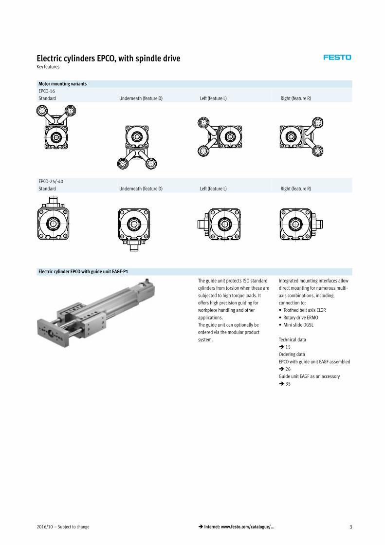
Motor mounting variants
EPCO-16
Standard Underneath (feature D) Left (feature L) Right (feature R)
EPCO-25/-40
Standard Underneath (feature D) Left (feature L) Right (feature R)
Electric cylinder EPCO with guide unit EAGF-P1
The guide unit protects ISO standard
cylinders from torsion when these are
subjected to high torque loads. It
offers high precision guiding for
workpiece handling and other
applications.
The guide unit can optionally be
ordered via the modular product
system.
Integrated mounting interfaces allow
direct mounting for numerous multi-
axis combinations, including
connection to:
� Toothed belt axis ELGR
� Rotary drive ERMO
� Mini slide DGSL
Technical data
� 15
Ordering data
EPCO with guide unit EAGF assembled
� 26
Guide unit EAGF as an accessory
� 35

Subject to change – 2016/104 � Internet: www.festo.com/catalogue/...
Electric cylinders EPCO, with spindle driveKey features
Possible combinations within the Optimised Motion Series (OMS)
Electric cylinder EPCO on toothed belt axis ELGR
1
2
1
2
Size Accessories
1 EPCO 2 ELGR Slot nut Centring sleeve Screw Washer
16 35 NST-3-M3 (x4) ZBH-7 (x2) M3x10 (x4) –
25 45 NST-5-M5 (x4) ZBH-7 (x2) M5x50 (x4) DIN125-A5.3 (x4)
40 55 NST-5-M5 (x4) ZBH-7 (x2) M5x65 (x4) DIN125-A5.3 (x4)
Rotary drive ERMO on electric cylinder EPCO
1
21 2
Size Accessories
1 ERMO 2 EPCO Centring sleeve Screw
12 16 ZBH-7 (x2) M4x16 (x2)
16 25 ZBH-7 (x2) M5x18 (x2)
25 40 ZBH-7 (x2) M5x20 (x2)
Rotary drive ERMO on mini slide DGSL
1
2
1
2
Size Accessories
1 ERMO 2 DGSL Centring sleeve Screw
12 12 ZBH-7 (x2) M4x18 (x2)
25 20 ZBH-9-7 (x2) M5x22 (x2)
25 25 ZBH-9-7 (x2) M5x22 (x2)
Rotary drive ERMO on mini slide EGSL
1
2
1
2
Size Accessories
1 ERMO 2 EGSL Centring sleeve Screw
12 35 ZBH-7 (x2) M4x12 (x2)
16 45 ZBH-7 (x2) M5x12 (x2)
25 55 ZBH-7 (x2) M5x14 (x2)
32 55 ZBH-7 (x2) M5x14 (x2)

2016/10 – Subject to change 5� Internet: www.festo.com/catalogue/...
Electric cylinders EPCO, with spindle driveKey features
Possible combinations within the Optimised Motion Series (OMS)
Electric cylinder EPCO on electric cylinder EPCO, horizontal
1
2
1
2
Size Accessories
1 EPCO 2 EPCO Centring sleeve Screw
16 25 ZBH-9 (x2) M6x40 (x4)
25 40 ZBH-9 (x2) M6x55 (x4)
Electric cylinder EPCO on electric cylinder EPCO, vertical
1
2
1
2
Size Accessories
1 EPCO 2 EPCO Centring sleeve Screw
16 25 ZBH-9 (x2) M5x18 (x4)
25 40 ZBH-9 (x2) M5x22 (x4)
Mini slide DGSL on electric cylinder EPCO
1
2
1
2
Size Accessories
1 DGSL 2 EPCO Centring sleeve Screw
8 (40mm)1) 16 ZBV-9-7 (x2) M4x16 (x2)
10 (30mm)1) 25 ZBV-9-7 (x2) M4x20 (x2)
12 (40mm)1) 40 ZBV-9-7 (x2) M5x20 (x2)
1) Minimum stroke

Subject to change – 2016/106 � Internet: www.festo.com/catalogue/...
Electric cylinders EPCO, with spindle driveType codes
EPCO – 16 – 100 – 3P – – – A – ST – E B
Type
EPCO Electric cylinder
Size
Stroke [mm]
Spindle pitch
Piston rod thread type
– Male thread
F Female thread
Piston rod extension
– None
…E 0 … 200 mm
Position sensing
– None
A Via proximity sensor
Motor type
ST Stepper motor
Measuring unit
– None
E Encoder
Brake
– None
B With brake

2016/10 – Subject to change 7� Internet: www.festo.com/catalogue/...
Electric cylinders EPCO, with spindle driveType codes
– – + 2.5E + C5 DIO N
Cable outlet direction
– Top (standard)
D Underneath
L Left
R Right
Guide unit
– None
KF Recirculating ball bearing guide with two guide
rods
Connecting cable to motor controller
– None
1.5E 1.5 m, straight plug
1.5EA 1.5 m, angled plug
2.5E 2.5 m, straight plug
2.5EA 2.5 m, angled plug
5E 5 m, straight plug
5EA 5 m, angled plug
7E 7 m, straight plug
7EA 7 m, angled plug
10E 10 m, straight plug
10EA 10 m, angled plug
Controller type
– None
C5 CMMO, 5 A
Bus protocol/activation
– None
DIO Digital I/O interface
LK IO-Link
Switching input/output
– None
N NPN
P PNP

Subject to change – 2016/108 � Internet: www.festo.com/catalogue/...
Electric cylinders EPCO, with spindle drivePeripherals overview
1
2
3
4
67
8
9
aJ
aA
aB
aC
aD
aE
aF
aG
aH
aI
bJ
bA
bB5
3
9
bC
bD
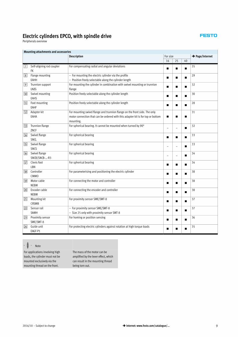
Mounting attachments and accessories
Description For size � Page/Internet
16 25 40
1 Right-angle clevis foot
LQG
For rod eye SGS– – �
34
2 Rod clevis
SGA
For rod eye SGS, for swivelling cylinder mounting– – �
35
3 Clevis foot
LBG
For rod eye SGS, for spherical bearing– – �
34
4 Rod eye
SGS/CRSGS
For spherical bearing� � �
35
5 Coupling piece
KSG
For compensating radial deviations– – �
35
6 Rod clevis
SG/CRSG
Permits a swivel motion of the cylinder in one plane� � �
35
2016/10 – Subject to change 9� Internet: www.festo.com/catalogue/...
Electric cylinders EPCO, with spindle drivePeripherals overview
Mounting attachments and accessories
Description For size � Page/Internet
16 25 40
7 Self-aligning rod coupler
FK
For compensating radial and angular deviations� � �
35
8 Flange mounting
EAHH
– For mounting the electric cylinder via the profile
– Position freely selectable along the cylinder length� � �
29
9 Trunnion support
LNZG
For mounting the cylinder in combination with swivel mounting or trunnion
flange� � �
32
aJ Swivel mounting
EAHS
Position freely selectable along the cylinder length� � �
30
aA Foot mounting
EAHF
Position freely selectable along the cylinder length� � �
28
aB Adapter kit
EAHA
For mounting swivel flange and trunnion flange on the front side. The only
motor connection that can be ordered with this adapter kit is for top or bottom
mounting.
� � �
31
aC Trunnion flange
ZNCF
For spherical bearing. It cannot be mounted when turned by 90°– – �
32
aD Swivel flange
SNCL
For spherical bearing� � �
33
aE Swivel flange
SNCS
For spherical bearing– – �
33
aF Swivel flange
SNCB/SNCB-…-R3
For spherical bearing– – �
34
aG Clevis foot
LBN
For spherical bearing� � �
34
aH Controller
CMMO
For parameterising and positioning the electric cylinder� � �
38
aI Motor cable
NEBM
For connecting the motor and controller� � �
38
bJ Encoder cable
NEBM
For connecting the encoder and controller� � �
38
bA Mounting kit
CRSMB
For proximity sensor SME/SMT-8� � �
37
bB Sensor rail
SAMH
– For proximity sensor SME/SMT-8
– Size 25 only with proximity sensor SMT-8� � �
37
bC Proximity sensor
SME/SMT-8
For homing or position sensing� � �
36
bD Guide unit
EAGF-P1
For protecting electric cylinders against rotation at high torque loads� � �
35
-H- Note
For applications involving high
loads, the cylinder must not be
mounted exclusively via the
mounting thread on the front.
The mass of the motor can be
amplified by the lever effect, which
can result in the mounting thread
being torn out.

Subject to change – 2016/1010 � Internet: www.festo.com/catalogue/...
Electric cylinders EPCO, with spindle driveTechnical data
Function -N- Size
16 … 40
-T- Stroke length
50 … 400 mm
-W- www.festo.com
General technical data
Size 16 25 40
Design Electric cylinder with recirculating ball spindle and motor
Piston rod thread
Male thread M6 M8 M10x1.25
Female thread M4 M6 M8
Working stroke [mm] 50 … 200 50 … 300 50 … 400
Stroke reserve [mm] 0
Max. torsion angle of the piston rod [°] ±2 ±1.5 1
Impact energy at the end positions [J] 0.1x 10⁻³ 0.2x 10⁻³ 0.4x 10⁻³
Position sensing Via proximity sensor
Type of mounting Via female thread
Via accessories
Mounting position Any
Mechanical data
Size 16 25 40
Spindle design 3P 8P 3P 10P 5P 12.7P
Spindle pitch1) [mm/rev] 3 8 3 10 5 12.7
Spindle diameter [mm] 8 8 10 10 12 12.7
Max. payload
Horizontal2) [kg] 24 8 60 20 120 40
Vertical [kg] 12 4 30 10 60 20
Max. feed force Fx [N] 125 50 350 105 650 250
Max. speed [mm/s] 125 300 150 500 180 460
Max. acceleration [m/s2] 10
Reversing backlash3) [mm] 0.1
Repetition accuracy [mm] ±0.02
1) Nominal value varies due to component tolerances.
2) Note max. lateral force.
3) In new condition.
Electrical data
Size 16 25 40
Motor
Nominal voltage [V DC] 24
Nominal current [A] 1.4 3 4.2
Brake
Nominal voltage [V DC] 24 ±10%
Rated output [W] 8
Holding torque [Nm] 0.09 0.5 1.13
Mass moment of inertia [kgmm2] 1.8 8.2 29

2016/10 – Subject to change 11� Internet: www.festo.com/catalogue/...
Electric cylinders EPCO, with spindle driveTechnical data
Electrical data
Size 16 25 40
Encoder
Rotary position encoder Incremental
Rotary position encoder measuring principle Opto-electrical
Pulses/revolution [1/rev] 500
Interface RS422, TTL, AB channel, zero index
Operating voltage of encoder [V DC] 5
Operating and environmental conditions
Ambient temperature1) [°C] 0 … +50
Storage temperature [°C] –20 … +60
Relative air humidity [%] 0 … 85 (non-condensing)
Degree of protection to IEC 60529 IP40
Corrosion resistance class CRC2) 1
Duty cycle [%] 100
CE marking (see declaration of conformity) To EU EMC Directive3)
Certification c UL us Recognized (OL)
RCM trademark
1) Note operating range of proximity sensors.
2) Corrosion resistance class CRC 1 to Festo standard FN 940070
Low corrosion stress. For dry indoor applications or transport and storage protection. Also applies to parts behind covers, in the non-visible interior area, and parts which are covered in the application (e.g. drive
trunnions).
3) For information about the applicability of the component see the manufacturer’s EC declaration of conformity at: www.festo.com/sp � Certificates.
If the component is subject to restrictions on usage in residential, office or commercial environments or small businesses, further measures to reduce the emitted interference may be necessary.
Weight [kg]
Size 16 25 40
Basic weight with 0 mm stroke
EPCO-… 0.62 1.04 2.49
EPCO-…-E 0.62 1.13 2.59
EPCO-…-B 0.68 1.22 2.71
EPCO-…-EB 0.68 1.28 2.77
EPCO-…-KF 1.22 … 1.28 2.12 … 2.36 4.40 … 4.68
Additional weight per 100 mm stroke
EPCO-… 0.17 0.34 0.55
EPCO-…-KF 0.25 0.45 0.73
Moving load with 0 mm stroke
EPCO-… 0.07 0.15 0.42
EPCO-…-KF 0.23 0.45 0.98
Moving load per 100 mm stroke
EPCO-… 0.020 0.026 0.049
EPCO-…-KF 0.10 0.136 0.229
Mass moment of inertia
Size 16 25 40
Spindle design 3P 8P 3P 10P 5P 12.7P
J0 with 0 mm stroke
EPCO-… [kg mm2] 2.28 2.29 9.33 9.40 33.25 33.75
EPCO-…-B [kg mm2] 2.97 2.98 10.63 10.70 34.55 35.05
jS per metre stroke [kg mm2/m] 2.53 2.65 4.87 5.78 11.66 16.70
jL per kg payload [kg mm2/kg] 0.23 1.62 0.23 2.54 0.64 4.09
The mass moment of inertia JA of the
electric cylinder is calculated as
follows:
JA = J0 + jS x working stroke [m] + jL x mmoving payload [kg]

Subject to change – 2016/1012 � Internet: www.festo.com/catalogue/...
Electric cylinders EPCO, with spindle driveTechnical data
Materials
Sectional view
1 4 52 3 6
Electric cylinder
1 Bearing cap Wrought aluminium alloy
2 Cylinder barrel Wrought aluminium alloy
3 Piston rod High-alloy stainless steel
4 Spindle Steel
5 Spindle nut Steel
6 Drive cover Wrought aluminium alloy
Note on materials RoHS-compliant
Contains PWIS (paint-wetting impairment substances)
Piston rod deflection f as a function of projection A and lateral force F
F
f
A
A [mm]
f [m
m]
EPCO-16 (F = 2 N)
EPCO-25 (F = 3 N)
EPCO-40 (F = 6 N)

2016/10 – Subject to change 13� Internet: www.festo.com/catalogue/...
Electric cylinders EPCO, with spindle driveTechnical data
Maximum permissible loads on the piston rod
If there are two or more forces and
torques simultaneously acting on
the piston rod, the following
equations must be satisfied:
|Fy|
Fymax.�
|Fz|
Fzmax.�
|My|
Mymax.�
|Mz|
Mzmax.� 1
|Fx| � Fxmax
|Mx| � Mxmax
F
A
Maximum permissible lateral forces Fymax and Fzmax on the piston rod as a function of projection A
A [mm]
F y m
ax.,
F z m
ax. [
N]
EPCO-16
EPCO-25
EPCO-40
Size 16 25 40
Spindle design 3P 8P 3P 10P 5P 12.7P
Fxmax (static) [N] 125 50 350 105 650 250
Mxmax [Nm] 0 0 0
Mymax, Mzmax [Nm] 0.6 1.0 3.3
-H- Note
PositioningDrives
engineering software
� www.festo.com

Subject to change – 2016/1014 � Internet: www.festo.com/catalogue/...
Electric cylinders EPCO, with spindle driveTechnical data
Payload m as a function of speed v and acceleration a
Horizontal mounting position
EPCO-16-3P EPCO-16-8P
a = 0.5 m/s2
a = 2.5 m/s2
a = 5 m/s2
a = 10 m/s2
For EPCO-… / EPCO-…-KF
EPCO-25-3P EPCO-25-10P
a = 0.5 m/s2
a = 2.5 m/s2
a = 5 m/s2
a = 10 m/s2
For EPCO-… / EPCO-…-KF
EPCO-40-5P EPCO-40-12.7P
a = 0.5 m/s2
a = 2.5 m/s2
a = 5 m/s2
a = 10 m/s2
For EPCO-… / EPCO-…-KF

2016/10 – Subject to change 15� Internet: www.festo.com/catalogue/...
Electric cylinders EPCO, with spindle driveTechnical data
Payload m as a function of speed v and acceleration a
Vertical mounting position
The moving tare weight of the guide unit (EPCO-…-KF) results in lower
acceleration values with identical payload and speed.
EPCO-16-3P EPCO-16-8P
a = 0 m/s2
a = 0.2 m/s2
a = 2.5 m/s2
a = 5 m/s2
a = 10 m/s2
For EPCO-…
a = 0 m/s2
a = 2.3 m/s2
a = 4.7 m/s2
a = 9.6 m/s2
For EPCO-…-KF
a = 0 m/s2
a = 1.2 m/s2
a = 2.5 m/s2
a = 5 m/s2
a = 10 m/s2
For EPCO-…
a = 0 m/s2
a = 1.2 m/s2
a = 3.4 m/s2
a = 7.8 m/s2
For EPCO-…-KF
EPCO-25-3P EPCO-25-10P
a = 0 m/s2
a = 0.2 m/s2
a = 2.5 m/s2
a = 5 m/s2
a = 10 m/s2
For EPCO-…
a = 0 m/s2
a = 2.4 m/s2
a = 4.9 m/s2
a = 9.8 m/s2
For EPCO-…-KF
a = 0 m/s2
a = 1.2 m/s2
a = 2.5 m/s2
a = 5 m/s2
a = 10 m/s2
For EPCO-…
a = 0 m/s2
a = 1.6 m/s2
a = 3.9 m/s2
a = 8.3 m/s2
For EPCO-…-KF
Further technical data for the guide
unit EAGF-P1
� www.festo.com/eagf-p1

Subject to change – 2016/1016 � Internet: www.festo.com/catalogue/...
Electric cylinders EPCO, with spindle driveTechnical data
Payload m as a function of speed v and acceleration a
Vertical mounting position
The moving tare weight of the guide unit (EPCO-…-KF) results in lower
acceleration values with identical payload and speed.
EPCO-40-5P EPCO-40-12.7P
a = 0 m/s2
a = 0.2 m/s2
a = 2.5 m/s2
a = 5 m/s2
a = 10 m/s2
For EPCO-…
a = 0 m/s2
a = 2.4 m/s2
a = 4.8 m/s2
a = 9.7 m/s2
For EPCO-…-KF
a = 0 m/s2
a = 1.2 m/s2
a = 2.5 m/s2
a = 5 m/s2
a = 10 m/s2
For EPCO-…
a = 0 m/s2
a = 1.8 m/s2
a = 4.0 m/s2
a = 8.5 m/s2
For EPCO-…-KF
Payload m as a function of travel distance l and positioning time t
Horizontal mounting position
The moving tare weight of the guide unit (EPCO-…-KF) results in longer
positioning times with identical payload and travel distance.
EPCO-16-3P EPCO-16-8P
t = 0.30 s
t = 0.60 s
t = 0.90 s
t = 1.20 s
t = 1.50 s
t = 1.80 s
t = 0.30 s
t = 0.60 s
t = 0.90 s
t = 1.20 s
t = 1.55 s
t = 1.85 s
For EPCO-… For EPCO-…-KF
t = 0.15 s
t = 0.30 s
t = 0.45 s
t = 0.60 s
t = 0.75 s
t = 0.90 s
t = 0.15 s
t = 0.30 s
t = 0.45 s
t = 0.65 s
t = 0.80 s
t = 0.95 s
For EPCO-… For EPCO-…-KF
Further technical data for the guide
unit EAGF-P1
� www.festo.com/eagf-p1

2016/10 – Subject to change 17� Internet: www.festo.com/catalogue/...
Electric cylinders EPCO, with spindle driveTechnical data
Payload m as a function of travel distance l and positioning time t
Horizontal mounting position
The moving tare weight of the guide unit (EPCO-…-KF) results in longer
positioning times with identical payload and travel distance.
EPCO-25-3P EPCO-25-10P
t = 0.30 s
t = 0.60 s
t = 0.90 s
t = 1.20 s
t = 1.50 s
t = 1.80 s
t = 2.10 s
t = 2.40 s
t = 1.50 s
t = 1.80 s
t = 2.10 s
t = 2.40 s
t = 0.30 s
t = 0.60 s
t = 0.90 s
t = 1.20 s
For EPCO-… For EPCO-…-KF
t = 0.15 s
t = 0.30 s
t = 0.45 s
t = 0.60 s
t = 0.75 s
t = 0.90 s
t = 1.05 s
For EPCO-… For EPCO-…-KF
t = 0.80 s
t = 0.95 s
t = 1.10 s
t = 0.15 s
t = 0.30 s
t = 0.45 s
t = 0.60 s
EPCO-40-5P EPCO-40-12.7P
t = 0.50 s
t = 1.00 s
t = 1.50 s
t = 2.00 s
t = 2.50 s
t = 0.50 s
t = 1.00 s
t = 1.55 s
t = 2.05 s
t = 2.55 s
For EPCO-… For EPCO-…-KF
t = 0.25 s
t = 0.50 s
t = 0.75 s
t = 1.00 s
t = 1.25 s
t = 0.25 s
t = 0.50 s
t = 0.80 s
t = 1.05 s
t = 1.30 s
For EPCO-… For EPCO-…-KF
Further technical data for the guide
unit EAGF-P1
� www.festo.com/eagf-p1

Subject to change – 2016/1018 � Internet: www.festo.com/catalogue/...
Electric cylinders EPCO, with spindle driveTechnical data
Payload m as a function of travel distance l and positioning time t
Vertical mounting position
The moving tare weight of the guide unit (EPCO-…-KF) results in longer
positioning times with identical payload and travel distance.
EPCO-16-3P EPCO-16-8P
t = 0.60 s
t = 1.20 s
t = 1.80 s
t = 2.40 s
t = 3.00 s
t = 0.60 s
t = 1.25 s
t = 1.85 s
t = 2.50 s
t = 3.10 s
For EPCO-… For EPCO-…-KF
t = 0.30 s
t = 0.60 s
t = 0.90 s
t = 1.20 s
t = 1.50 s
t = 0.35 s
t = 0.65 s
t = 1.00 s
t = 1.30 s
t = 1.65 s
For EPCO-… For EPCO-…-KF
EPCO-25-3P EPCO-25-10P
t = 0.60 s
t = 1.20 s
t = 1.80 s
t = 2.40 s
t = 3.00 s
t = 3.60 s
t = 4.20 s
t = 3.05 s
t = 3.70 s
t = 4.30 s
t = 0.60 s
t = 1.20 s
t = 1.85 s
t = 2.45 s
For EPCO-… For EPCO-…-KF
t = 0.30 s
t = 0.60 s
t = 0.90 s
t = 1.20 s
t = 1.50 s
t = 0.30 s
t = 0.65 s
t = 0.95 s
t = 1.25 s
t = 1.60 s
For EPCO-… For EPCO-…-KF
Further technical data for the guide
unit EAGF-P1
� www.festo.com/eagf-p1

2016/10 – Subject to change 19� Internet: www.festo.com/catalogue/...
Electric cylinders EPCO, with spindle driveTechnical data
Payload m as a function of travel distance l and positioning time t
Vertical mounting position
The moving tare weight of the guide unit (EPCO-…-KF) results in longer
positioning times with identical payload and travel distance.
EPCO-40-5P EPCO-40-12.7P
t = 1.00 s
t = 2.00 s
t = 3.00 s
t = 4.00 s
t = 5.00 s
t = 6.00 s
t = 7.00 s
t = 5.15 s
t = 6.20 s
t = 7.20 s
t = 1.05 s
t = 2.05 s
t = 3.10 s
t = 4.10 s
For EPCO-… For EPCO-…-KF
t = 0.50 s
t = 1.00 s
t = 1.50 s
t = 2.00 s
t = 2.50 s t = 2.70 s
t = 0.55 s
t = 1.10 s
t = 1.60 s
t = 2.15 s
For EPCO-… For EPCO-…-KF
Feed force F as a function of speed v and acceleration a
The moving tare weight of the guide unit (EPCO-…-KF) results in lower
acceleration values with identical feed force and speed.
EPCO-16-3P EPCO-16-8P
a = 0 m/s2
a = 0.2 m/s2
a = 2.5 m/s2
a = 5 m/s2
a = 10 m/s2
a = 0 m/s2
a = 2.3 m/s2
a = 4.7 m/s2
a = 9.6 m/s2
For EPCO-… For EPCO-…-KF
a = 0 m/s2
a = 1.2 m/s2
a = 2.5 m/s2
a = 5 m/s2
a = 10 m/s2
a = 0 m/s2
a = 1.2 m/s2
a = 3.4 m/s2
a = 7.8 m/s2
For EPCO-… For EPCO-…-KF
Further technical data for the guide
unit EAGF-P1
� www.festo.com/eagf-p1

Subject to change – 2016/1020 � Internet: www.festo.com/catalogue/...
Electric cylinders EPCO, with spindle driveTechnical data
Feed force F as a function of speed v and acceleration a
The moving tare weight of the guide unit (EPCO-…-KF) results in lower
acceleration values with identical feed force and speed.
EPCO-25-3P EPCO-25-10P
a = 0 m/s2
a = 0.2 m/s2
a = 2.5 m/s2
a = 5 m/s2
a = 10 m/s2
a = 0 m/s2
a = 2.4 m/s2
a = 4.9 m/s2
a = 9.8 m/s2
For EPCO-… For EPCO-…-KF
a = 0 m/s2
a = 1.2 m/s2
a = 2.5 m/s2
a = 5 m/s2
a = 10 m/s2
a = 0 m/s2
a = 1.6 m/s2
a = 3.9 m/s2
a = 8.3 m/s2
For EPCO-… For EPCO-…-KF
EPCO-40-5P EPCO-40-12.7P
a = 0 m/s2
a = 0.2 m/s2
a = 2.5 m/s2
a = 5 m/s2
a = 10 m/s2
a = 0 m/s2
a = 2.4 m/s2
a = 4.8 m/s2
a = 9.7 m/s2
For EPCO-… For EPCO-…-KF
a = 0 m/s2
a = 1.2 m/s2
a = 2.5 m/s2
a = 5 m/s2
a = 10 m/s2
a = 0 m/s2
a = 1.8 m/s2
a = 4.0 m/s2
a = 8.5 m/s2
For EPCO-… For EPCO-…-KF
Further technical data for the guide
unit EAGF-P1
� www.festo.com/eagf-p1

2016/10 – Subject to change 21� Internet: www.festo.com/catalogue/...
Electric cylinders EPCO, with spindle driveTechnical data
Calculating the mean feed force Fxm with the electric cylinder EPCO
The peak feed force value must not
exceed the maximum feed force within
a movement cycle. The peak value is
generally achieved in vertical
operation during the acceleration
phase of the upwards stroke. If the
maximum feed force is exceeded, this
can increase wear and thus shorten
the service life of the ball screw
spindle. The maximum speed must
likewise not be exceeded.
Fx �� Fxmax.
vx �� vxmax.
and
Mean feed force (to DIN 69051-4)
During operation, the continuous feed
force may be briefly exceeded up to
the maximum feed force. The continu
ous feed force must, however, be
adhered to when averaged over a
movement cycle.
Fxm �� Fxdauer
Fxm ��3 � Fx3 �
vxvxm
�q
100� �� �
Fxm ��3 Fx13 �
vx1vxm
�q1
100� Fx2
3 �vx2vxm
�q2
100� Fx3
3 �vx3vxm
�q3
100� ���� F x
[N]
q1 q2 q3q [100%]
Fx1
Fx2
Fx3
Fxmax
Fxm
Mean feed speed (to DIN 69051-4)
vxm ��� vx �q
100� vx1 �
q1
100� vx2 �
q2
100� vx3 �
q3
100� ���
q [100%]q1 q2 q3
v x [m
m/s
]
vx1
vx3
vx2vxmax
vxm
Fx Feed force
Fxm Mean feed force
Fxmax Max. feed force
Fxcontinuous Continuous feed force
q Time
vx Feed speed
vxm Mean feed speed
vxmax Max. feed speed

Subject to change – 2016/1022 � Internet: www.festo.com/catalogue/...
Electric cylinders EPCO, with spindle driveTechnical data
Mean feed force F as a function of running performance L (to DIN 69051-4)
EPCO-16 EPCO-25
EPCO-16-3P
EPCO-16-8P
EPCO-25-3P
EPCO-25-10P
EPCO-40
EPCO-40-5P
EPCO-40-12.7P
-H- Note
� The specifications for running
performance are based on experi
mentally determined and theoret
ically calculated data. The running
performance attainable in practice
can deviate considerably from the
specified curves under different
parameters.
Pin allocation
Motor Encoder
EPCO-16 EPCO-25/-40 EPCO-16/-25/-40
PIN Function PIN Function PIN Function
1 String A 1 String A 1 Signal trace A
2 String A/ 2 String A/ 2 Signal trace A/
3 String B 3 String B 3 Signal trace B
4 String B/ 4 String B/ 4 Signal trace B/
5 n.c. 5 n.c. 5 GND encoder
6 n.c. 6 n.c. 6 Signal trace N
7 Brake +24 V DC1) 7 Brake +24 V DC1) 7 Signal trace N/
8 Brake GND1) 8 Brake GND1) 8 VCC auxiliary supply +5 V
– – 9 n.c. GND Shield on plug housing
1) Only on motors with brake.

2016/10 – Subject to change 23� Internet: www.festo.com/catalogue/...
Electric cylinders EPCO, with spindle driveTechnical data
Dimensions Download CAD data � www.festo.com
Size 16
2 Encoder connection:
Round plug M12, 8-pin, pins
cable length: 250 mm
1 Motor connection:
Round plug M12, 8-pin, socket
cable length: 350 mm
3 Min. bending radius of the
cables: 60 mm
Size 25, 40
+ = plus stroke length1 Motor connection:
SUB-D plug, 9-pin, pins
2 Encoder connection:
Round plug M12, 8-pin, pins
Size AM B1 B2 D1 D2 H1 H2 H3 KK L1 L2
[mm] –0.5
0.05
1
16 12 30 24 13.27 M4 44 30 24 M6 143 127
25 16 40 32.5 17.27 M5 42+0.3 40 32.5 M8 174.6 156.6
40 19 55 42 26.52 M6 56.4 55 42 M10x1.25 214.2 192.7
Size L3 L4 L5 L6 MM ß1 ß2
EPCO-…
[mm] -E -B -EB –0.15 –0.1
16 701 701 961.5 961.5 16 3.7 10 8 7 10
25 661 94.41.2 114.41.3 127.41.3 18 4.2 12 10 9 13
40 73.50.8 102.51.1 123.51.1 1381.1 21.5 4.7 14 12 10 17
Subject to change – 2016/1024 � Internet: www.festo.com/catalogue/...
Electric cylinders EPCO, with spindle driveTechnical data
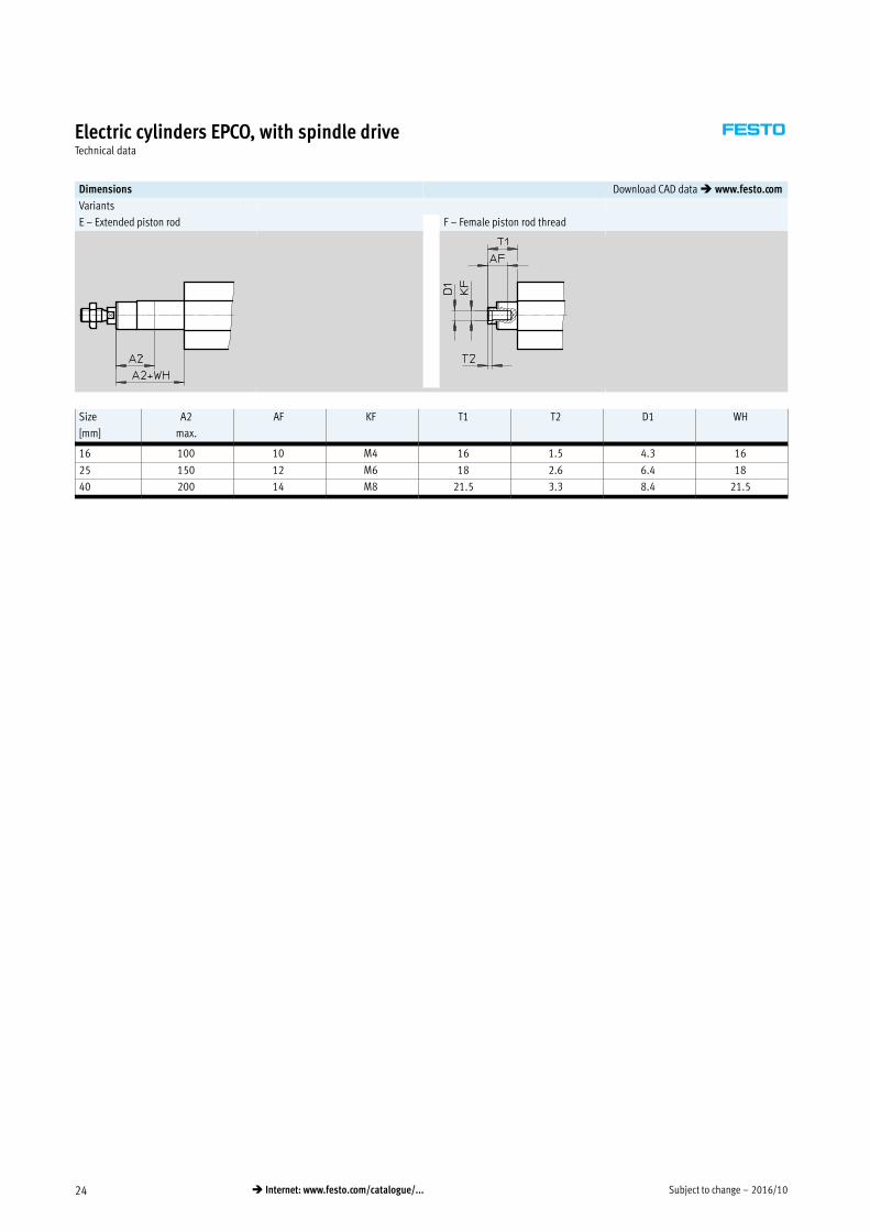
Dimensions Download CAD data � www.festo.com
Variants
E – Extended piston rod F – Female piston rod thread
Size
[mm]
A2
max.
AF KF T1 T2 D1 WH
16 100 10 M4 16 1.5 4.3 16
25 150 12 M6 18 2.6 6.4 18
40 200 14 M8 21.5 3.3 8.4 21.5

2016/10 – Subject to change 25� Internet: www.festo.com/catalogue/...
Electric cylinders EPCO, with spindle driveTechnical data
Ordering data – EPCO-16 (stock items)
Stroke
[mm]
Part No. Type Stroke
[mm]
Part No. Type
Spindle pitch 3 mm, with encoder Spindle pitch 8 mm, with encoder
50 1476415 EPCO-16-50-3P-ST-E 50 1476522 EPCO-16-50-8P-ST-E
100 1476417 EPCO-16-100-3P-ST-E 100 1476524 EPCO-16-100-8P-ST-E
150 1476419 EPCO-16-150-3P-ST-E 150 1476526 EPCO-16-150-8P-ST-E
200 1476421 EPCO-16-200-3P-ST-E 200 1476528 EPCO-16-200-8P-ST-E
Ordering data – EPCO-25 (stock items)
Stroke
[mm]
Part No. Type Stroke
[mm]
Part No. Type
Spindle pitch 3 mm, with encoder Spindle pitch 10 mm, with encoder
50 1470698 EPCO-25-50-3P-ST-E 50 1470769 EPCO-25-50-10P-ST-E
100 1470700 EPCO-25-100-3P-ST-E 100 1470771 EPCO-25-100-10P-ST-E
150 1470702 EPCO-25-150-3P-ST-E 150 1470773 EPCO-25-150-10P-ST-E
200 1470704 EPCO-25-200-3P-ST-E 200 1470775 EPCO-25-200-10P-ST-E
300 1470706 EPCO-25-300-3P-ST-E 300 1470777 EPCO-25-300-10P-ST-E
Ordering data – EPCO-40 (stock items)
Stroke
[mm]
Part No. Type Stroke
[mm]
Part No. Type
Spindle pitch 5 mm, with encoder Spindle pitch 12.7 mm, with encoder
50 1472501 EPCO-40-50-5P-ST-E 50 1472617 EPCO-40-50-12.7P-ST-E
100 1472503 EPCO-40-100-5P-ST-E 100 1472619 EPCO-40-100-12.7P-ST-E
150 1472505 EPCO-40-150-5P-ST-E 150 1472621 EPCO-40-150-12.7P-ST-E
200 1472507 EPCO-40-200-5P-ST-E 200 1472623 EPCO-40-200-12.7P-ST-E
300 1472509 EPCO-40-300-5P-ST-E 300 1472625 EPCO-40-300-12.7P-ST-E
-H- Note
Variants ordered via modular
product system � 26
-H- Note
Position sensing is only possible in
combination with feature "A"
(position sensing) � 26 (modular
product system)

Subject to change – 2016/1026 � Internet: www.festo.com/catalogue/...
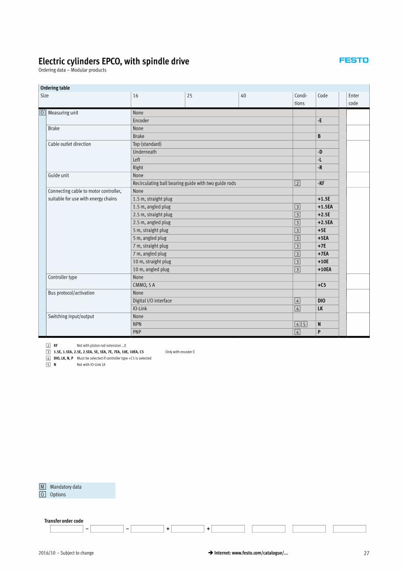
Electric cylinders EPCO, with spindle driveOrdering data – Modular products
Ordering table
Size 16 25 40 Condi
tions
Code Enter
code
0M Module no. 1476585 1470874 1472887
Function Electric cylinder EPCO EPCO
Size 16 25 40 -…
Stroke [mm] 50 -…
75
100
125
150
175
200
– 250
– 300
– 350
– 400
Spindle pitch [mm] 3 3 -…P
5
8
10
12.7
0O Piston rod thread type Male thread
Female thread -F
Piston rod extension [mm] None
1 … 100 1 … 150 1 … 200 -…E
Position sensing None
Via proximity sensor 1 -A
0M Motor type Stepper motor -ST ST
1 A Must be selected if encoder E is not selected.
Transfer order code
EPCO – – – – – – – ST
Mandatory data
Options
M
O
2016/10 – Subject to change 27� Internet: www.festo.com/catalogue/...
Electric cylinders EPCO, with spindle driveOrdering data – Modular products
Ordering table
Size 16 25 40 Condi
tions
Code Enter
code
0O Measuring unit None
Encoder -E
Brake None
Brake B
Cable outlet direction Top (standard)
Underneath -D
Left -L
Right -R
Guide unit None
Recirculating ball bearing guide with two guide rods 2 -KF
Connecting cable to motor controller,
suitable for use with energy chains
None
1.5 m, straight plug +1.5E
1.5 m, angled plug 3 +1.5EA
2.5 m, straight plug 3 +2.5E
2.5 m, angled plug 3 +2.5EA
5 m, straight plug 3 +5E
5 m, angled plug 3 +5EA
7 m, straight plug 3 +7E
7 m, angled plug 3 +7EA
10 m, straight plug 3 +10E
10 m, angled plug 3 +10EA
Controller type None
CMMO, 5 A +C5
Bus protocol/activation None
Digital I/O interface 4 DIO
IO-Link 4 LK
Switching input/output None
NPN 4 5 N
PNP 4 P
2 KF Not with piston rod extension …E
3 1.5E, 1.5EA, 2.5E, 2.5EA, 5E, 5EA, 7E, 7EA, 10E, 10EA, C5 Only with encoder E
4 DIO, LK, N, P Must be selected if controller type +C5 is selected
5 N Not with IO-Link LK
Transfer order code
– – + +
Mandatory data
Options
M
O
Subject to change – 2016/1028 � Internet: www.festo.com/catalogue/...
Electric cylinders EPCO, with spindle driveAccessories
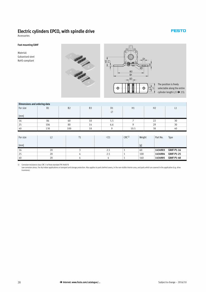
Foot mounting EAHF
Material:
Galvanised steel
RoHS-compliant
The position is freely
selectable along the entire
cylinder length L2 (� 23).
Dimensions and ordering data
For size B1 B2 B3 D1
H1 H2 L1
[mm]
16 86 60 10 5.5 7 22 30
25 106 80 14 6.6 9 29 30
40 130 100 18 9 10.5 38 40
For size L2 T1 ß1 CRC1) Weight Part No. Type
[mm] [g]
16 20 3 2.5 1 60 1434903 EAHF-P1-16
25 20 4 2.5 1 100 1434904 EAHF-P1-25
40 20 4 4 1 160 1434905 EAHF-P1-40
1) Corrosion resistance class CRC 1 to Festo standard FN 940070
Low corrosion stress. For dry indoor applications or transport and storage protection. Also applies to parts behind covers, in the non-visible interior area, and parts which are covered in the application (e.g. drive
trunnions).
2016/10 – Subject to change 29� Internet: www.festo.com/catalogue/...
Electric cylinders EPCO, with spindle driveAccessories
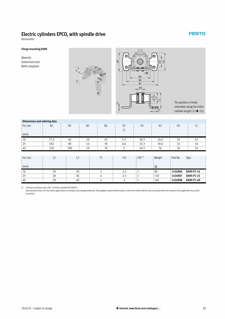
Flange mounting EAHH
Material:
Galvanised steel
RoHS-compliant
The position is freely
selectable along the entire
cylinder length L2 (� 23).
Dimensions and ordering data
For size B1 B2 B3 B4 D1
H1 H2 H3 L1
[mm]
16 77.2 60 10 45 5.5 38.3 34.6 20 43
25 102 80 14 59 6.6 52.3 50.6 32 44
40 119 100 18 76 9 64.5 56 36 54
For size L2 L3 T1 ß1 CRC1) Weight Part No. Type
[mm] [g]
16 20 30 3 2.5 1 80 1434906 EAHH-P1-16
25 20 30 4 2.5 1 150 1434907 EAHH-P1-25
40 20 40 4 4 1 240 1434908 EAHH-P1-40
1) Corrosion resistance class CRC 1 to Festo standard FN 940070
Low corrosion stress. For dry indoor applications or transport and storage protection. Also applies to parts behind covers, in the non-visible interior area, and parts which are covered in the application (e.g. drive
trunnions).

Subject to change – 2016/1030 � Internet: www.festo.com/catalogue/...
Electric cylinders EPCO, with spindle driveAccessories
Swivel mounting EAHS
Material:
Galvanised steel
RoHS-compliant
The position is freely
selectable along the entire
cylinder length L2 (� 23).
Dimensions and ordering data
For size B1 B2 B3 B4 D1
H1 H2
[mm] e9
16 71 60 10 45 8 33 21
25 95 80 14 59 12 37.5 27
40 118 100 18 76 16 55 36.5
For size L1 L2 T1 ß1 CRC1) Weight Part No. Type
[mm] [g]
16 30 20 3 2.5 1 80 1434909 EAHS-P1-16
25 30 20 4 2.5 1 140 1434910 EAHS-P1-25
40 40 20 4 4 1 260 1434911 EAHS-P1-40
1) Corrosion resistance class CRC 1 to Festo standard FN 940070
Low corrosion stress. For dry indoor applications or transport and storage protection. Also applies to parts behind covers, in the non-visible interior area, and parts which are covered in the application (e.g. drive
trunnions).

2016/10 – Subject to change 31� Internet: www.festo.com/catalogue/...
Electric cylinders EPCO, with spindle driveAccessories
Adapter kit EAHA Material:
Galvanised steel
RoHS-compliant
Dimensions and ordering data
For size B1 B2 B3 D1 H1 H2 H3 H4
[mm]
16 45 18 10 M4 35.9 29.8 18 15
25 59 26 14 M5 49 44 26 20
40 76 38 18 M6 66.9 60.8 38 27.5
For size L1 L2 L3 T1 ß1 CRC1) Weight Part No. Type
[mm] [g]
16 139 20 30 3 2.5 1 210 1434900 EAHA-P1-16
25 174 20 30 4 2.5 1 480 1434901 EAHA-P1-25
40 193.4 20 40 4 4 1 770 1434902 EAHA-P1-40
1) Corrosion resistance class CRC 1 to Festo standard FN 940070
Low corrosion stress. For dry indoor applications or transport and storage protection. Also applies to parts behind covers, in the non-visible interior area, and parts which are covered in the application (e.g. drive
trunnions).
Subject to change – 2016/1032 � Internet: www.festo.com/catalogue/...
Electric cylinders EPCO, with spindle driveAccessories
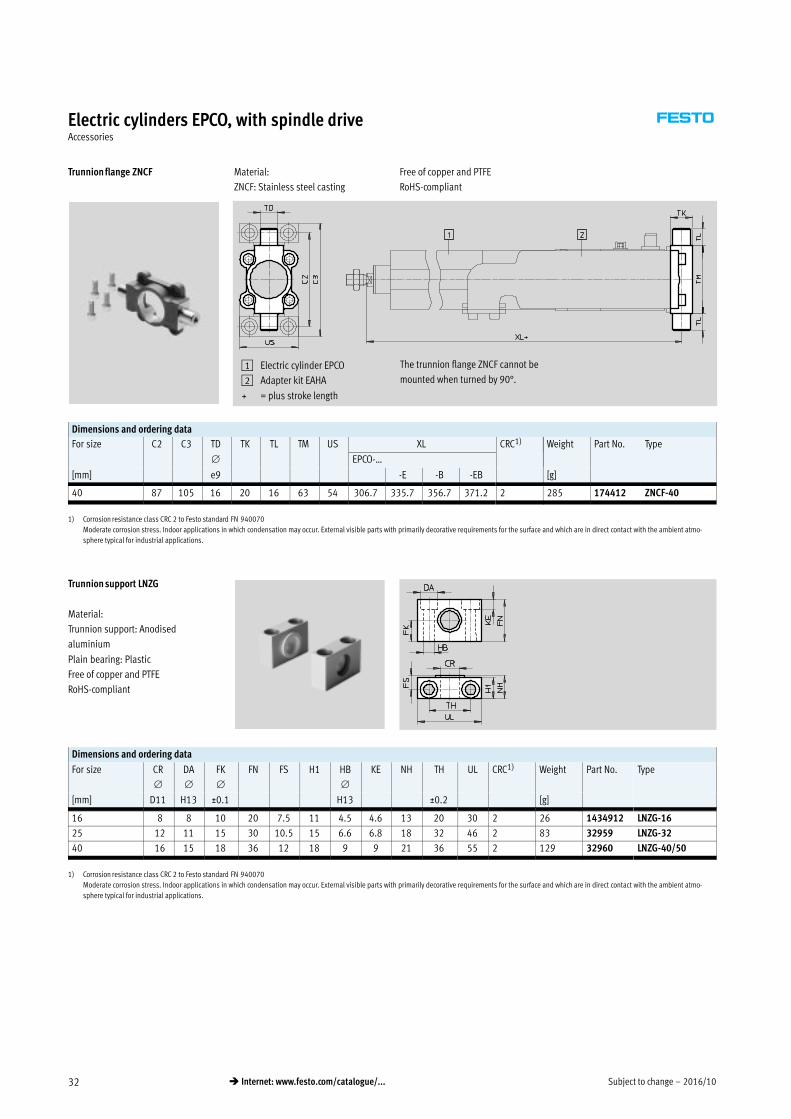
Trunnion flange ZNCF Material:
ZNCF: Stainless steel casting
Free of copper and PTFE
RoHS-compliant
1 Electric cylinder EPCO
2 Adapter kit EAHA
+ = plus stroke length
The trunnion flange ZNCF cannot be
mounted when turned by 90°.
Dimensions and ordering data
For size C2 C3 TD TK TL TM US XL CRC1) Weight Part No. Type
EPCO-…
[mm] e9 -E -B -EB [g]
40 87 105 16 20 16 63 54 306.7 335.7 356.7 371.2 2 285 174412 ZNCF-40
1) Corrosion resistance class CRC 2 to Festo standard FN 940070
Moderate corrosion stress. Indoor applications in which condensation may occur. External visible parts with primarily decorative requirements for the surface and which are in direct contact with the ambient atmo
sphere typical for industrial applications.
Trunnion support LNZG
Material:
Trunnion support: Anodised
aluminium
Plain bearing: Plastic
Free of copper and PTFE
RoHS-compliant
Dimensions and ordering data
For size CR
DA
FK
FN FS H1 HB
KE NH TH UL CRC1) Weight Part No. Type
[mm] D11 H13 ±0.1 H13 ±0.2 [g]
16 8 8 10 20 7.5 11 4.5 4.6 13 20 30 2 26 1434912 LNZG-16
25 12 11 15 30 10.5 15 6.6 6.8 18 32 46 2 83 32959 LNZG-32
40 16 15 18 36 12 18 9 9 21 36 55 2 129 32960 LNZG-40/50
1) Corrosion resistance class CRC 2 to Festo standard FN 940070
Moderate corrosion stress. Indoor applications in which condensation may occur. External visible parts with primarily decorative requirements for the surface and which are in direct contact with the ambient atmo
sphere typical for industrial applications.

2016/10 – Subject to change 33� Internet: www.festo.com/catalogue/...
Electric cylinders EPCO, with spindle driveAccessories
Swivel flange SNCS Material:
Die-cast aluminium
Free of copper and PTFE
RoHS-compliant
1 Electric cylinder EPCO
2 Adapter kit EAHA
+ = plus stroke length
Dimensions and ordering data
For size CN
E EP EX FL LT MS RA TG
[mm] +0.2 ±0.2 +1
40 12+0.015 54–0.5 12 16 25 16 17+0.5 17.5 38
For size XC CRC1) Weight Part No. Type
EPCO-…
[mm] -E -B -EB [g]
40 321.7 350.7 371.7 386.2 2 122 174398 SNCS-40
1) Corrosion resistance class CRC 2 to Festo standard FN 940070
Moderate corrosion stress. Indoor applications in which condensation may occur. External visible parts with primarily decorative requirements for the surface and which are in direct contact with the ambient atmo
sphere typical for industrial applications.
Swivel flange SNCL Material:
Wrought aluminium alloy
Free of copper and PTFE
RoHS-compliant
1 Electric cylinder EPCO
2 Adapter kit EAHA
+ = plus stroke length
Dimensions and ordering data
For size CD EW FL L MR XC CRC1) Weight Part No. Type
EPCO-…
[mm] H9 h12 ±0.2 –0.5 -E -B -EB [g]
16 6 12 16 10 6 237 237 263 263 2 21 537791 SNCL-16
25 8 16 20 14 8 269.6 298 318 331 2 41 537793 SNCL-25
40 12 28 25 16 12 321.7 350.7 371.7 386.2 2 95 174405 SNCL-40
1) Corrosion resistance class CRC 2 to Festo standard FN 940070
Moderate corrosion stress. Indoor applications in which condensation may occur. External visible parts with primarily decorative requirements for the surface and which are in direct contact with the ambient atmo
sphere typical for industrial applications.

Subject to change – 2016/1034 � Internet: www.festo.com/catalogue/...
Electric cylinders EPCO, with spindle driveAccessories
Swivel flange SNCB Material:
Die-cast aluminium
Free of copper and PTFE
RoHS-compliant
1 Electric cylinder EPCO
2 Adapter kit EAHA
+ = plus stroke length
Dimensions and ordering data
For size CB EK FL L MR UB XC CRC1) Weight Part No. Type
EPCO-…
[mm] H14 e8 ±0.2 h14 -E -B -EB [g]
40 28 12 25 16 12 52 321.7 350.7 371.7 386.2 2 155 174391 SNCB-40
1) Corrosion resistance class CRC 2 to Festo standard FN 940070
Moderate corrosion stress. Indoor applications in which condensation may occur. External visible parts with primarily decorative requirements for the surface and which are in direct contact with the ambient atmo
sphere typical for industrial applications.
Ordering data – Mounting attachments Technical data � Internet: clevis foot
Designation For size Part No. Type Designation For size Part No. Type
Clevis foot LBG Right-angle clevis foot LQG
40 31762 LBG-40 40 31769 LQG-40
Clevis foot LBN
16 6058 LBN-12/16
25 6059 LBN-20/25
40 195861 LBN-40

2016/10 – Subject to change 35� Internet: www.festo.com/catalogue/...
Electric cylinders EPCO, with spindle driveAccessories
Ordering data – Piston rod attachments Technical data � Internet: piston rod attachment
Designation For size Part No. Type Designation For size Part No. Type
Rod eye SGS Rod clevis SG
16 9254 SGS-M6 16 3110 SG-M6
25 9255 SGS-M8 25 3111 SG-M8
40 9261 SGS-M10x1,25 40 6144 SG-M10x1,25
Self-aligning rod coupler FK Rod clevis SGA
16 2061 FK-M6 40 32954 SGA-M10x1,25
25 2062 FK-M8
40 6140 FK-M10x1,25
Coupling piece KSG
40 32963 KSG-M10x1,25
Ordering data – Guide unit Technical data � Internet: eagf
For size Stroke
[mm]
Part No. Type
16 50 3192932 EAGF-P1-KF-16-50
100 3192934 EAGF-P1-KF-16-100
150 3192936 EAGF-P1-KF-16-150
200 3192938 EAGF-P1-KF-16-200
75, 125, 175 3192939 EAGF-P1-KF-16-
25 50 3192943 EAGF-P1-KF-25-50
100 3192945 EAGF-P1-KF-25-100
150 3192947 EAGF-P1-KF-25-150
200 3192949 EAGF-P1-KF-25-200
300 3192951 EAGF-P1-KF-25-300
75, 125, 175, 250 3192952 EAGF-P1-KF-25-
40 50 3192955 EAGF-P1-KF-40-50
100 3192957 EAGF-P1-KF-40-100
150 3192959 EAGF-P1-KF-40-150
200 3192961 EAGF-P1-KF-40-200
300 3192963 EAGF-P1-KF-40-300
75, 125, 175, 250, 350, 400 3192966 EAGF-P1-KF-40-

Subject to change – 2016/1036 � Internet: www.festo.com/catalogue/...
Electric cylinders EPCO, with spindle driveAccessories
Ordering data – Proximity sensor for T-slot, magneto-resistive Technical data � Internet: smt
Type of mounting Switching
output
Electrical connection Cable length Part No. Type
[m]
N/O contact
Inserted in the slot from above,
flush with the cylinder profile,
short design
PNP Cable, 3-wire 2.5 574335 SMT-8M-A-PS-24V-E-2,5-OE
Plug M8x1, 3-pin 0.3 574334 SMT-8M-A-PS-24V-E-0,3-M8D
Plug M12x1, 3-pin 0.3 574337 SMT-8M-A-PS-24V-E-0,3-M12
NPN Cable, 3-wire 2.5 574338 SMT-8M-A-NS-24V-E-2,5-OE
Plug M8x1, 3-pin 0.3 574339 SMT-8M-A-NS-24V-E-0,3-M8D
N/C contact
Inserted in the slot from above,
flush with the cylinder profile,
short design
PNP Cable, 3-wire 7.5 574340 SMT-8M-A-PO-24V-E-7,5-OE
Ordering data – Proximity sensor for T-slot, magnetic reed Technical data � Internet: sme
Type of mounting Switching
output
Electrical connection Cable length Part No. Type
[m]
N/O contact
Inserted in the slot from above, flush with
the cylinder profile
Contacting Cable, 3-wire 2.5 543862 SME-8M-DS-24V-K-2,5-OE
5.0 543863 SME-8M-DS-24V-K-5,0-OE
Cable, 2-wire 2.5 543872 SME-8M-ZS-24V-K-2,5-OE
Plug M8x1, 3-pin 0.3 543861 SME-8M-DS-24V-K-0,3-M8D
Inserted in the slot lengthwise, flush
with the cylinder profile
Contacting Cable, 3-wire 2.5 150855 SME-8-K-LED-24
Plug M8x1, 3-pin 0.3 150857 SME-8-S-LED-24
N/C contact
Inserted in the slot lengthwise, flush
with the cylinder profile
Contacting Cable, 3-wire 7.5 160251 SME-8-O-K-LED-24
-H- Note
Position sensing is only possible in
combination with feature "A"
(position sensing) � 26 (modular
product system)
Ordering data – Connecting cable Technical data � Internet: km8
Description Connection Cable length Part No. Type
[m]
Straight socket
Union nut M8, both ends 3-pin 0.5 541346 NEBU-M8G3-K-0.5-M8G3
1.0 541347 NEBU-M8G3-K-1-M8G3
2.5 541348 NEBU-M8G3-K-2.5-M8G3
5.0 541349 NEBU-M8G3-K-5-M8G3

2016/10 – Subject to change 37� Internet: www.festo.com/catalogue/...
Electric cylinders EPCO, with spindle driveAccessories
Sensor mounting
The sensor mountings can only be
attached within the highlighted area
due to the asymmetry of the internal
magnets.
The proximity sensors may not switch
reliably if they are mounted outside of
this area.
The overall length of the sensor rail
SAMH corresponds to the length of the
sensing range plus approx. 10 mm
adjustment range on either side for
the proximity sensors.
L3
Size L1 L2 L3
16 29 95 15
25 33 121 20
40 40 150 27.5
Ordering data – Sensor mounting for T-slot
For size Description Length
[mm]
Part No. Type
Sensor rail
16, 25, 40 Size 25 can only be used with proximity sensor
SMT-8 (magneto-resistive).
50 1600093 SAMH-N8-SR-50
100 1600118 SAMH-N8-SR-100
Mounting kit
16, 25, 40 – 35 525565 CRSMB-8-32/100

Subject to change – 2016/1038 � Internet: www.festo.com/catalogue/...
Electric cylinders EPCO, with spindle driveAccessories
Ordering data – Cables1)
For size Description Cable length
[m]
Part No. Type
Motor cable
16 Straight plug
– Min. bending radius: 62 mm
– Suitable for use with energy chains
– Ambient temp.:
–40 … +80 °C
1.5 1449600 NEBM-SM12G8-E-1.5-Q5-LE6
2.5 1449601 NEBM-SM12G8-E-2.5-Q5-LE6
5.0 1449602 NEBM-SM12G8-E-5-Q5-LE6
7.0 1449603 NEBM-SM12G8-E-7-Q5-LE6
10.0 1449604 NEBM-SM12G8-E-10-Q5-LE6
25/-40 Angled plug
– Min. bending radius: 62 mm
– Suitable for use with energy chains
– Ambient temp.:
–40 … +80 °C
1.5 1450736 NEBM-S1W9-E-1.5-Q5-LE6
2.5 1450737 NEBM-S1W9-E-2.5-Q5-LE6
5.0 1450738 NEBM-S1W9-E-5-Q5-LE6
7.0 1450739 NEBM-S1W9-E-7-Q5-LE6
10.0 1450740 NEBM-S1W9-E-10-Q5-LE6
Straight plug
– Min. bending radius: 62 mm
– Suitable for use with energy chains
– Ambient temp.:
–40 … +80 °C
1.5 1450368 NEBM-S1G9-E-1.5-Q5-LE6
2.5 1450369 NEBM-S1G9-E-2.5-Q5-LE6
5.0 1450370 NEBM-S1G9-E-5-Q5-LE6
7.0 1450371 NEBM-S1G9-E-7-Q5-LE6
10.0 1450372 NEBM-S1G9-E-10-Q5-LE6
Encoder cable
16/-25/-40 Straight plug
– Min. bending radius: 68 mm
– Suitable for use with energy chains
– Ambient temp.:
–40 … +80 °C
1.5 1451586 NEBM-M12G8-E-1.5-LE8
2.5 1451587 NEBM-M12G8-E-2.5-LE8
5.0 1451588 NEBM-M12G8-E-5-LE8
7.0 1451589 NEBM-M12G8-E-7-LE8
10.0 1451590 NEBM-M12G8-E-10-LE8
25/-40 Angled plug
– Min. bending radius: 68 mm
– Suitable for use with energy chains
– Ambient temp.:
–40 … +80 °C
1.5 1451674 NEBM-M12W8-E-1.5-LE8
2.5 1451675 NEBM-M12W8-E-2.5-LE8
5.0 1451676 NEBM-M12W8-E-5-LE8
7.0 1451677 NEBM-M12W8-E-7-LE8
10.0 1451678 NEBM-M12W8-E-10-LE8
1) Other cable lengths on request.
Ordering data – Motor controller Technical data � Internet: cmmo
Description Part No. Type
With I/O interface
Switching input/output PNP 1512316 CMMO-ST-C5-1-DIOP
Switching input/output NPN 1512317 CMMO-ST-C5-1-DION
With IO-Link
Switching input/output PNP 1512320 CMMO-ST-C5-1-LKP


![EPCO BDA E 2017-11c 8076283k1 - Festo16 Festo – EPCO – 2017-11c ’(& 12.2 ˙ ˘ 16 25 40 0 EPCO-…-ST aE 0 6ƒ aE(S1) 2 ” [V] 24 2 × [A] 1.4 3.0 4.2 23 ) [Nm] 0.09 0.5 1.13](https://cdn.vdocuments.mx/doc/165x107/60c5686d9c116772976a436a/epco-bda-e-2017-11c-8076283k1-festo-16-festo-a-epco-a-2017-11c-a-122.jpg)
