
ELCT 501:
Digital System Design
Lecture 4: CAD tools (Continued)
Dr. Mohamed Abd El Ghany,
Department of Electronics and Electrical Engineering
Basic VHDL Concept Via an Example
2 Dr. Mohamed Abd el Ghany
Department of Electronics and Electrical Engineering
ELCT 501: Digital System
Design
Winter 2011
Problem: write VHDL code for
1-bit adder
4-bit adder

1-bit adder
3 Dr. Mohamed Abd el Ghany
Department of Electronics and Electrical Engineering
ELCT 501: Digital System
Design
Winter 2011
B A
SUM
Cin Cout
Inputs:
A (1 bit)
B (1 bit)
Cin (1 bit)
Outputs
Sum = A xor B xor Cin
Cout = AB + BC + AC

1-bit adder
4 Dr. Mohamed Abd el Ghany
Department of Electronics and Electrical Engineering
ELCT 501: Digital System
Design
Winter 2011

1-bit adder
5 Dr. Mohamed Abd el Ghany
Department of Electronics and Electrical Engineering
ELCT 501: Digital System
Design
Winter 2011
VHDL Code (1-Bit Adder)
entity <File Name> is
Port ( <Define Inputs & Outputs>);
end <File Name>;
architecture <……> of <Entity Name> is
begin
{Code implementation}
end <……>;

4-bit adder
6 Dr. Mohamed Abd el Ghany
Department of Electronics and Electrical Engineering
ELCT 501: Digital System
Design
Winter 2011
Unit 1
1-Bit
Adder
B0 A0
SUM 0
Cin= 0 1-Bit
Adder
B1 A1
SUM 1
w1 w2 w3 1-Bit
Adder
B2 A2
SUM 2
1-Bit
Adder
B3 A3
SUM 3
Cout
Unit 2 Unit 3 Unit 4

4-bit adder
7 Dr. Mohamed Abd el Ghany
Department of Electronics and Electrical Engineering
ELCT 501: Digital System
Design
Winter 2011
B0 A0
w3 w2 w1
Unit 1
1-Bit
Adder Cin= 0
1-Bit
Adder
B1 A1
1-Bit
Adder
1-Bit
Adder
SUM 3
Cout
SUM 2 SUM 1 SUM 0
Unit 2 Unit 3 Unit 4
B2 A2 B3 A3
4-bit adder - VHDL
8 Dr. Mohamed Abd el Ghany
Department of Electronics and Electrical Engineering
ELCT 501: Digital System
Design
Winter 2011
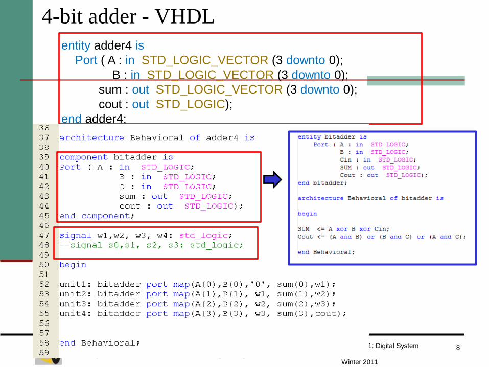
entity adder4 is
Port ( A : in STD_LOGIC_VECTOR (3 downto 0);
B : in STD_LOGIC_VECTOR (3 downto 0);
sum : out STD_LOGIC_VECTOR (3 downto 0);
cout : out STD_LOGIC);
end adder4;

Basic VHDL Concept Via an Example
9 Dr. Mohamed Abd el Ghany
Department of Electronics and Electrical Engineering
ELCT 501: Digital System
Design
Winter 2011
Problem: write VHDL
code to specify the
circuit of one-digit BCD
(Binary Coded Decimal)
adder (shown in the
following figure)

Binary Coded Decimal Representation
10 Dr. Mohamed Abd el Ghany
Department of Electronics and Electrical Engineering
ELCT 501: Digital System
Design
Winter 2011
Z= X+Y
IF Z <= 9, then S = Z and carry-out = 0
IF Z > 9 , then X = Z + 6 and carry-out = 1
X 0 1 1 1 7
+Y + 0 1 0 1 +5
Z 1 1 0 0 12
+ 0 1 1 0
1 0 0 1 0
S = 2

Binary Coded Decimal Representation
11 Dr. Mohamed Abd el Ghany
Department of Electronics and Electrical Engineering
ELCT 501: Digital System
Design
Winter 2011
Z= X+Y
IF Z <= 9, then S = Z and carry-out = 0
IF Z > 9 , then X = Z + 6 and carry-out = 1
X 1 0 0 0 8
+Y + 1 0 0 1 +9
Z 1 0 0 0 1 17
+ 0 1 1 0
1 0 1 1 1
S = 7

Binary Coded Decimal Representation
12 Dr. Mohamed Abd el Ghany
Department of Electronics and Electrical Engineering
ELCT 501: Digital System
Design
Winter 2011

Basic VHDL Concept Via an Example
13 Dr. Mohamed Abd el Ghany
Department of Electronics and Electrical Engineering
ELCT 501: Digital System
Design
Winter 2011
Problem: write VHDL code to specify the circuit in
the following figure
comparator
circuit

Comparator Circuit
14 Dr. Mohamed Abd el Ghany
Department of Electronics and Electrical Engineering
ELCT 501: Digital System
Design
Winter 2011
X< Y is detected by N xor V=1
X=Y is detected by Z=1
X≤Y is detected by Z+(N xor V)=1
X>Y is detected by Z+(N xor V)=1
X≥Y is detected by N xor V=1

Comparator Circuit
15 Dr. Mohamed Abd el Ghany
Department of Electronics and Electrical Engineering
ELCT 501: Digital System
Design
Winter 2011

Digital Logic Classification
16 Dr. Mohamed Abd el Ghany
Department of Electronics and Electrical Engineering
ELCT 501: Digital System
Design
Winter 2011
Digital Logic
Combinational
o/p’s depend on i/p’s only
E.g. Logic Gates
Sequential
o/p’s depend on i/p’s &
state of storage elements
Asynchronous
E.g. Latches
Synchronous
E.g. Flip Flops
VHDL for Combinational Circuit
17 Dr. Mohamed Abd el Ghany
Department of Electronics and Electrical Engineering
ELCT 501: Digital System
Design
Winter 2011
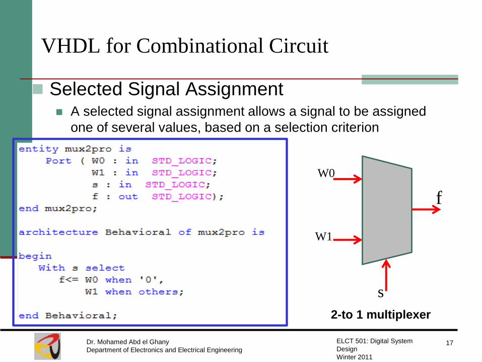
Selected Signal Assignment A selected signal assignment allows a signal to be assigned
one of several values, based on a selection criterion
W0
W1
f
s
2-to 1 multiplexer

VHDL for Combinational Circuit
18 Dr. Mohamed Abd el Ghany
Department of Electronics and Electrical Engineering
ELCT 501: Digital System
Design
Winter 2011
Selected Signal Assignment
W0
W3
f
2
4-to 1 multiplexer
W1
W2
s
VHDL for Combinational Circuit
19 Dr. Mohamed Abd el Ghany
Department of Electronics and Electrical Engineering
ELCT 501: Digital System
Design
Winter 2011
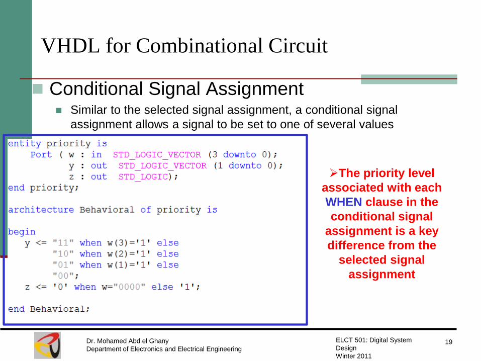
Conditional Signal Assignment Similar to the selected signal assignment, a conditional signal
assignment allows a signal to be set to one of several values
The priority level
associated with each
WHEN clause in the
conditional signal
assignment is a key
difference from the
selected signal
assignment
VHDL for Combinational Circuit
20 Dr. Mohamed Abd el Ghany
Department of Electronics and Electrical Engineering
ELCT 501: Digital System
Design
Winter 2011
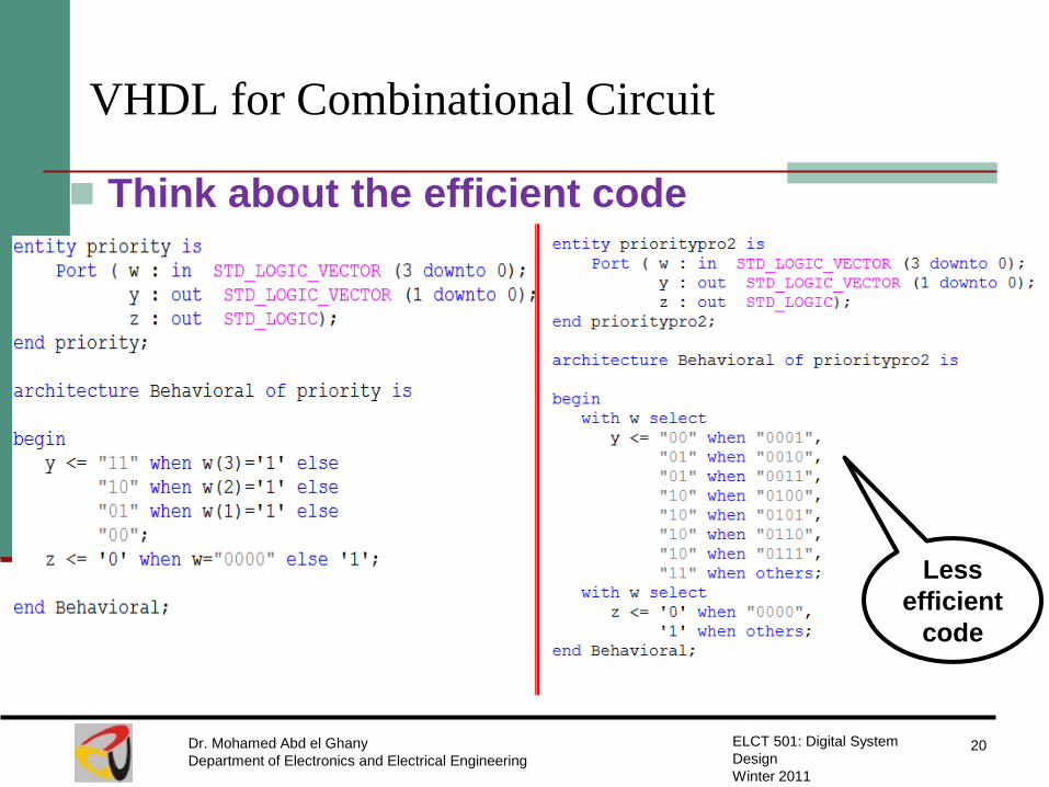
Think about the efficient code
Less
efficient
code
VHDL for Combinational Circuit
21 Dr. Mohamed Abd el Ghany
Department of Electronics and Electrical Engineering
ELCT 501: Digital System
Design
Winter 2011
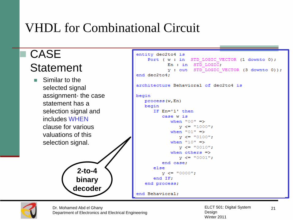
CASE
Statement Similar to the
selected signal
assignment- the case
statement has a
selection signal and
includes WHEN
clause for various
valuations of this
selection signal.
2-to-4
binary
decoder
VHDL for Combinational Circuit
22 Dr. Mohamed Abd el Ghany
Department of Electronics and Electrical Engineering
ELCT 501: Digital System
Design
Winter 2011
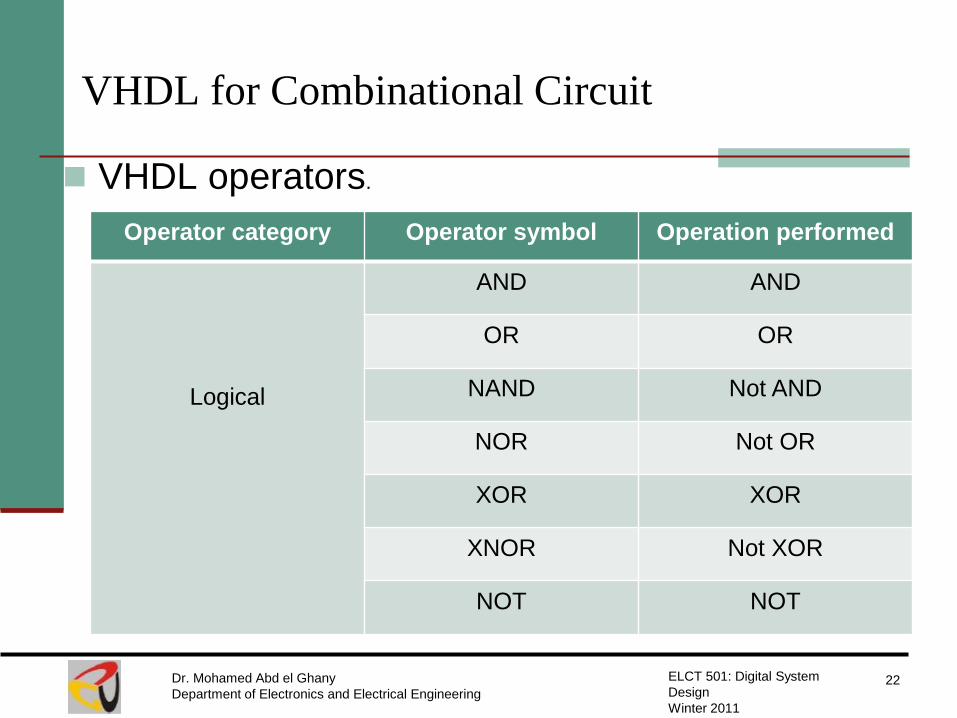
VHDL operators.
Operator category Operator symbol Operation performed
Logical
AND AND
OR OR
NAND Not AND
NOR Not OR
XOR XOR
XNOR Not XOR
NOT NOT
VHDL for Combinational Circuit
23 Dr. Mohamed Abd el Ghany
Department of Electronics and Electrical Engineering
ELCT 501: Digital System
Design
Winter 2011
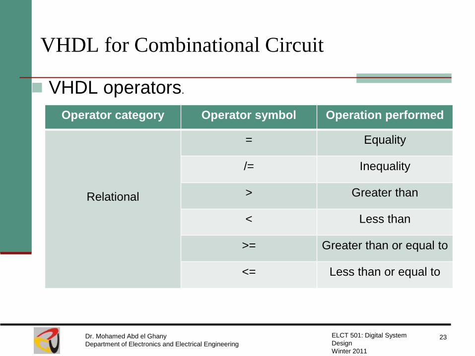
VHDL operators.
Operator category Operator symbol Operation performed
Relational
= Equality
/= Inequality
> Greater than
< Less than
>= Greater than or equal to
<= Less than or equal to

VHDL for Combinational Circuit
24 Dr. Mohamed Abd el Ghany
Department of Electronics and Electrical Engineering
ELCT 501: Digital System
Design
Winter 2011
VHDL operators.
Operator category Operator symbol Operation performed
Arithmetic
+ Addition
- Subtraction
Concatenation & Concatenation
Examples:.
C <= A – B;
Puts the difference of A
and B into C
D <= A & B;
using three-bit vectors; A(2 downto 0),
B(2 downto 0), the output D will be:
D= a1a2a3b1b2b3 (six-bit vector)

VHDL for Combinational Circuit
25 Dr. Mohamed Abd el Ghany
Department of Electronics and Electrical Engineering
ELCT 501: Digital System
Design
Winter 2011
VHDL operators.
Operator category Operator symbol Operation performed
Shift and Rotate
SLL Shift left logical
SRL Shift right logical
ROL Rotate left
ROR Rotate right
Examples:.
B <= A SLL;
b2=a1, b1= a0, and b0= 1
B <= A ROR 2;
b2=a1, b1= a0, and b0= a2

VHDL for Sequential Circuit
26 Dr. Mohamed Abd el Ghany
Department of Electronics and Electrical Engineering
ELCT 501: Digital System
Design
Winter 2011
With the info we encountered so far, can we
build this?
When the button is pushed:
1) Turn on the light if it is off
2) Turn off the light if it is on
The light should change state within a
second of the button press
button light
No!
1. “state” – i.e. the circuit should have memory
2. The o/p changes by an i/p “event” (pushing a button)
What is a latch?
27 Dr. Mohamed Abd el Ghany
Department of Electronics and Electrical Engineering
ELCT 501: Digital System
Design
Winter 2011

D Latch
28 Dr. Mohamed Abd el Ghany
Department of Electronics and Electrical Engineering
ELCT 501: Digital System
Design
Winter 2011
Logic diagram Function table

VHDL for D Latch
29 Dr. Mohamed Abd el Ghany
Department of Electronics and Electrical Engineering
ELCT 501: Digital System
Design
Winter 2011
Function table
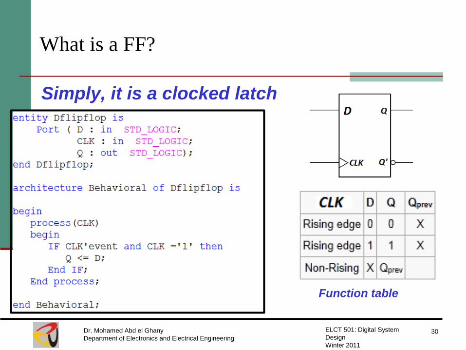
What is a FF?
30 Dr. Mohamed Abd el Ghany
Department of Electronics and Electrical Engineering
ELCT 501: Digital System
Design
Winter 2011
Simply, it is a clocked latch
Function table

Alternative code for a D Flip-flop
31 Dr. Mohamed Abd el Ghany
Department of Electronics and Electrical Engineering
ELCT 501: Digital System
Design
Winter 2011
Function table
A process that uses a
WAIT UNTIL statement
is a special case
because the sensitivity
list is omitted

D Flip-flop with Asynchronous reset
32 Dr. Mohamed Abd el Ghany
Department of Electronics and Electrical Engineering
ELCT 501: Digital System
Design
Winter 2011
Function table

D Flip-flop with synchronous reset
33 Dr. Mohamed Abd el Ghany
Department of Electronics and Electrical Engineering
ELCT 501: Digital System
Design
Winter 2011
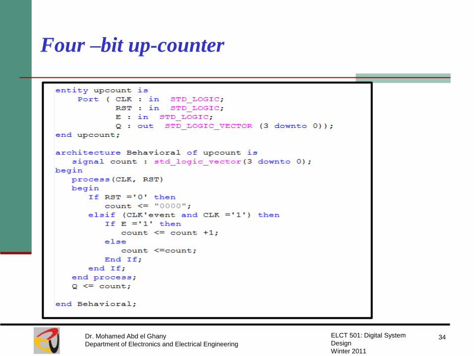
Four –bit up-counter
34 Dr. Mohamed Abd el Ghany
Department of Electronics and Electrical Engineering
ELCT 501: Digital System
Design
Winter 2011

Four –bit up-counter : testing
35 Dr. Mohamed Abd el Ghany
Department of Electronics and Electrical Engineering
ELCT 501: Digital System
Design
Winter 2011
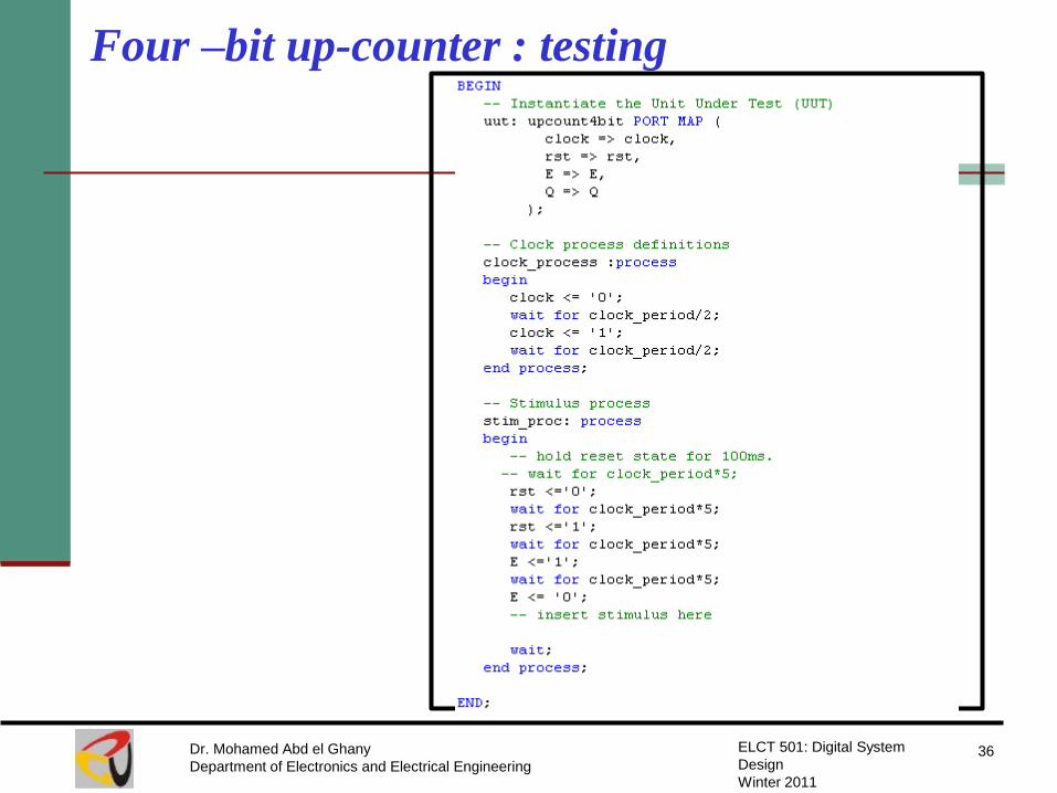
Four –bit up-counter : testing
36 Dr. Mohamed Abd el Ghany
Department of Electronics and Electrical Engineering
ELCT 501: Digital System
Design
Winter 2011

Four –bit up-counter
37 Dr. Mohamed Abd el Ghany
Department of Electronics and Electrical Engineering
ELCT 501: Digital System
Design
Winter 2011


