
PROPORTIONALCONTROLS
HO
M
A B
a b
P T
AB V P T W Y X
OM
A
Y
V
T
P
Up to 24.5 MPa (3550 PSI), 400 L/min (106 U.S.GPM)
No.1
EH SERIES PROPORTIONAL ELECTRO-HYDRAULIC
CONTROL VALVES
Pub. EC-1301
Pilot Relief / Relief / Reducing and Relieving /Flow Control / Flow Control and Relief / Directional and Flow Control
Pilot Relief Valves .................................................. Page 3
Relief Valves ........................................................... Page 4
Reducing and Relieving Valves ............................ Page 5
Flow Control Valves Flow Control and Check Valves ........................... Page 6
Flow Control and Relief Valves ............................ Page 7
Directional and Flow Control Valves ................... Page 8
High Response Type Directional and Flow Control Valves ................... Page 9
This catalogue introduce the outline of the EH series. Please refer to the catalogue titled "EH Series-Hybrid Components" (Cat. No. Pub. JC-1320) for the details such as performance characteristics and dimensions.

PROPORTIONALCONTROLS
3
4
1
2
5
5
1.
2. 3. 4.
5.
EH SERIES
No.2
Pilot Relief / Relief / Reducing and Relieving /Flow Control / Flow Control and Relief / Directional and Flow Control
High-accuracy, simple, convenientEH Series realizes your dreams.
Highly accurate hydraulic control can be obtained only by supplying 24 V DC power and inputting a command signal voltage of 0 to 5 V .
Why simple ?
3
4
The power amplifier and pressure sensor are integrated in the control valve. Furthermore, the closed-loop control design greatly improves the linearity, hysteresis and stability in control pressure.
Why high-accuracy ?1 2 Control pressure can be shown digitally on
the optional pressure display panel .
Why convenient ?
5
Analog voltages can be output by using the incorporated sensor for monitoring pressure, etc. . Pressure can be displayed remotely with the Yuken's digital panel metre or any indicators obtainable in the market and also can be transmitted into a computer.
6
If any trouble arises in the system and the command signal does not match to the output, the alarm signal is dispatched. The trouble, if arises, can be easily detected by monitoring the dispatch of the alarm signal with sequence controller or computer.
7
Power amplifier
Details of Proportional Electro-hydraulic Relief Valve
1
Pressure display panel (option)5
Pressure sensor incorporated
2
Voltage output for pressure monitor
6
Command signal voltage input
4
24 V DC power supply
3
Alarm signal output7
The sensor in directional control valves is to monitor the spool position. Valves without sensor are also available in both pressure control valves and directional control valves. Open-loop types are also available. EHDFG-04 and 06: ±24V DC power supply is needed. EHDFG-01, 03, 04 and 06: 0 to ±5V DC command signal is needed. EHDFG-04 and 06: The spool displacement is shown as a percentage.

PROPORTIONALCONTROLS
1
2
1
1
1
1
2
H
1. 2.
1. 2.
Model NumbersEHDG-01∗Description
Max. Operating Pres.
Max. Flow
Min. Flow
Pressure Adjustment Range
Coil Resistance
Hysteresis
Repeatability
Frequency Response
Supply Electric Power
Power Input (Max.)
Input Impedance
Alarm Signal Output (Open Collector)
Input Signal
Ambient Temperature
Pressure Signal Output
24.5 MPa (3550 PSI)
2 L/min (.53 U.S.GPM)
0.3 L/min (.08 U.S.GPM)
Refer to Model Number Designation
10
Less than 3% (1%)
Less than 1%
Ω
C : 10 (27) HzH : 12 (27) Hz
B : 10 (27) Hz(-90 degree)
24 V DC (21 to 28 V DC Included Ripple)
28 W
10 k Ω
0 - 50°C (32 - 122°F) (With Circulated Air)
C :H :
B : 6.9 MPa (1000 PSI) / 5 V DC
C : 5 V DC /H : 5 V DC /
B : 5 V DC /
15.7 MPa (2275 PSI) / 5 V DC24.5 MPa (3550 PSI) / 5 V DC
6.9 MPa (1000 PSI)15.7 MPa (2275 PSI)24.5 MPa (3550 PSI)
Voltage: Max. 30 V DC Current: Max. 40 mA
Propor- tional Electro- Hydraulic Pilot Relief Valve
EHD :
EHDSeries
Number
GType of
Mounting
-01 V -B -S D -1 -PN T15 -50M10
Sub-Plate Mounting
G:01
Valve Size
Applicable Control
For general use
None :
Vent Control of Relief Valve (Omit if not required)
V :C: 1 - 15.7
(145 - 2275)
H: 1.2 - 24.5 (175 - 3550)
B: 0.5 - 6.9 (70 - 1000)
Pres. Adj. Range MPa (PSI)
Open- Loop
None :
Open- Loop with Sensor
S :
Closed- Loop
L :
Control Type DPM
Without DPM
None :
Without DPM
None :
With DPM
D :
Safety Valve
Without Safety Valve
None :
With Safety Valve
1 :
P-Line Orifice
T-Line Orifice
Design Number
50
P-B Line Orifice
T15 T13 T11
Without Orifice (Standard)
PN :
Standard Orifice
M10 :
Open-Loop Type Open-Loop Type with Safety Valve
Open-Loop Type with Sensor
Open-Loop Type with Safety Valve & Sensor
Closed-Loop Type Closed-Loop Type with Safety Valve
Graphic Symbols
No.3
EH SERIES Pilot Relief Valves
EHDG-01∗-∗-∗∗-∗-PNT∗∗-50 1/8, Sub-plate Mounting
The valve can be used as a pilot valve of the Proportional Electro-Hydraulic Control Valves. The valve can also be used as a relief valve for the hydraulic system where a small flow rate and continuous pressure control are required.
Specifications
The value in ( ) is for the closed-loop type. The repeatability of the valve is obtained by having it tested independently on the conditions similar to its original testing.
Model Number Designation
For closed-loop models, specify applicable control code "V" even though the valve may not be used as vent control of relief valve.
Standard of T-line Orifice. Pres. Adj. Range B: T15, C: T13, H: T11.

PROPORTIONALCONTROLS
1
2
1
1
1. 2.
1
1
1
1
Model NumbersEHBG-03
Description
Pressure Adjustment Range Coil Resistance Hysteresis Repeatability
Frequency Response
Supply Electric Power
Power Input (Max.)
Input ImpedanceAlarm Signal Output (Open Collector)
Input Signal
Ambient Temperature
Pressure Signal Output
Proportional Electro- Hydraulic Relief Valve
EHB :
EHB
Series Number
GType of
Mounting
-03 -C -S D -50
Sub-Plate Mounting
G:
03
Valve Size
C: 0.6 [0.8] - 15.7 (85 [115] - 2275)
H: 0.6 [0.8] - 24.5 (85 [115] - 3550)
Pres. Adj. Range MPa (PSI)
Open-LoopNone :
Open-Loop with Sensor
S :
Closed-LoopL :
Control Type DPM
Without DPMNone :
Without DPMNone :
With DPMD :
Design Number
50
EHBG-06 EHBG-10
Max. Flow
Min. Flow
Max. Operating Pres.
Ω
C : 10 (22) HzH : 10 (25) Hz(-90 degree)
24 V DC (21 to 28 V DC Included Ripple)
0 - 50°C (32 - 122°F) (With Circulated Air)
C : 5 V DC /H : 5 V DC /
15.7 MPa (2275 PSI)24.5 MPa (3550 PSI)
Voltage: Max. 30 V DC Current: Max. 40 mA
24.5 MPa (3550 PSI)
100 L/min (26.4 U.S.GPM)
200 L/min (52.8 U.S.GPM)
400 L/min (106 U.S.GPM)
3 L/min (.79 U.S.GPM)
3 L/min (.79 U.S.GPM)
3 L/min (.79 U.S.GPM)
Refer to Model Number Designation 10
Less than 2% (1%) Less than 1%
C : 7 (15) HzH : 9.5 (18) Hz(-90 degree)
C : 7 (10.5) HzH : 6 (14) Hz(-90 degree)
28 W
C :H :
15.7 MPa (2275 PSI) / 5 V DC24.5 MPa (3550 PSI) / 5 V DC (At Max. Flow)
10 kΩ
06C: 0.9 [1.0] - 15.7 (130 [145] - 2275)
H: 0.9 [1.0] - 24.5 (130 [145] - 3550)
10C: 1.1 [1.4] - 15.7 (160 [205] - 2275)
H: 1.1 [1.4] - 24.5 (160 [205] - 3550)
50
50
Graphic Symbols
Closed-Loop Type
Open-Loop Type
Open-Loop Type with Sensor
EH SERIES Relief Valves
EHBG-03/06/10 (3/8, 3/4, 1-1/4) Sub-plate Mounting
These valves, consist of a small size but high performance EH series electro-hydraulic proportional pilot relief valve and a low noise type relief valve. The valves control the system pressure proportionally through a controlled input voltage.
Specifications
The value in ( ) is for the closed-loop type. The repeatability of the valve is obtained by having it tested independently on the conditions similar to its original testing.
Model Number Designation
Each value of minimum adjustment pressure is of at 50% flow rate of the Max. Flow shown on the Specifications. The value in [ ] is for the closed-loop type.
No.4

PROPORTIONALCONTROLS
2
1.
2.
1 1
H
Model Numbers
Description
Pressure Adjustment Range Coil Resistance Hysteresis Repeatability
Frequency Response
Supply Electric Power
Power Input (Max.)
Input Impedance
Input Signal
Ambient Temperature
Pressure Signal Output
Proportional Electro-Hydraulic Reducing & Relieving Valve
EHRB:
EHRB
Series Number
GType of
Mounting
-06 -C -S D -50
Sub-Plate Mounting
G:
Valve Size
C:H:
Pres. Adj. Range MPa (PSI)
Open-LoopNone :
Open-Loop with Sensor
S :
Control Type DPM
Without DPMNone :
With DPMD :
Design Number
50
EHRBG-06 EHRBG-10
Max. Flow
Max. Relieving Flow
Max. Operating Pres.
Ω
24 V DC (21 to 28 V DC Included Ripple)
0 - 50°C (32 - 122°F) (With Circulated Air)
24.5 MPa (3550 PSI)
100 L/min (26.4 U.S.GPM)
250 L/min (66 U.S.GPM)
35 L/min (9.24 U.S.GPM)
15 L/min (3.96 U.S.GPM)
Refer to Model Number Designation 10
Less than 3% Less than 1%
28 W
10 kΩ
06
10
C : 3 HzH : 3 Hz
B : 4 Hz(-90 degree)
C :H :
B : 6.9 MPa (1000 PSI) / 5 V DC13.7 MPa (2000 PSI) / 5 V DC20.6 MPa (3000 PSI) / 5 V DC
(at Flow Rate Zero)
C : 5 V DC /H : 5 V DC /
B : 5 V DC / 6.9 MPa (1000 PSI)13.7 MPa (2000 PSI)20.6 MPa (3000 PSI)
B: 0.8 - 6.9 (115 - 1000)1.2 - 13.7 (175 - 2000)1.5 - 20.6 (220 - 3000)
C:H:
B: 0.9 - 6.9 (130 - 1000)1.2 - 13.7 (175 - 2000)1.5 - 20.6 (220 - 3000)
50
Graphic Symbols
Open-Loop Type
Open-Loop Type with Sensor
EH SERIES Reducing & Relieving Valves
EHRBG-06/10 (3/4, 1-1/4) Sub-plate Mounting
These valves consist of a small size but high performance electro-hydraulic proportional pilot relief valve and reducing valve with relief function. The valves control the system pressure proportionally through a controlled input voltage. Moreover, a good response speed in reducing the pressure even at a large load capacity can be obtained with the relief function of the valves.
Specifications
The figures shown are those obtained where the differential pressure between the secondary pressure port and tank port is 14 MPa (2030 PSI). The repeatability of the valve is obtained by having it tested independently on the conditions similar to its original testing.
Model Number Designation
No.5

PROPORTIONALCONTROLS
2
1. 2.
1
Model Numbers
Description
Supply Electric Power
Power Input (Max.)
Input signal
Input Impedance
Proportional Electro-Hydraulic Flow Control Valve
EHF :
EHF
Series Number
GType of
Mounting
-03 -60 -50
Sub-Plate Mounting
G:
Valve Size Max. Metred Flow L/min (U.S.GPM)
Internal PilotNone :
Design Number
50
EHF∗G-03- EHF∗G-06-250
Max. Operating Pres.
24 V DC (21 to 28 V DC Included Ripple)
0 - 50°C (32 - 122°F) (With Circulated Air)
20.6 (3000)
28 W
Max. Metred Flow / 5V DC
10 kΩ
03
06 50
60125
MPa (PSI)
Max. Metred FlowL/min (U.S.GPM)
Min. Metred FlowL/min (U.S.GPM)
Min. Differential Pressure
Free Flow L/min (U.S.GPM)MPa (PSI)
(Only with Check Valve)at Normal
at TransitionPilot Flow
L/min (U.S.GPM)
Min. Pilot PressureMPa (PSI)
Frequency Response
Hysteresis
Repeatability
Coil Resistance
Ambient Temperature
12 Hz (-90 degree)
Less than 3%
Less than 1%
10 Ω
1 (.26)
1.0 (145)
130 (34.3)
0.5 ( .13) 2.6 ( .69)
1.0 (145)
1 ( .26) 4 ( 1.06)
1.5 (215)
24.5 (3550)
250 (66)
2.5 (.66)
1.0 (145)
280 (73.9)
60 ( 15.8) 125 ( 33)
60125
::
60 ( 15.8) 125 ( 33)
60125
::
Proportional Electro-Hydraulic Flow Control and Check Valve
EHFC :
-E
Pilot Connection
External PilotE:
250 ( 66)250 :
Graphic Symbols
Internal Pilot External Pilot
Internal Pilot External Pilot
O
M O
M
O
M O
M
EHFG
EHFCG
EH SERIES Flow Control (and Check) Valves
EHFG/EHFCG-03/06 (3/8, 3/4) Sub-plate Mounting
The system flow rate can be controlled remotely as desired by regulating input voltage. Further, since pressure and temperature compensation functions are provided, the preselected flow rate is not affected by pressure (load) or temperature (fluid viscosity).
Specifications
Minimum differential pressure means fine pressure compensation at inlet and outlet port. The repeatability of the valve is obtained by having it tested independently on the conditions similar to its original testing.
Model Number Designation
No.6
PROPORTIONALCONTROLS
H
Model Numbers
Description
EHFBSeries
Number
GType of
Mounting
-03 -60 -50
Sub-Plate Mounting
G:
Valve Size
Max. Metred Flow L/min (U.S.GPM)
Without Propor- tional Pilot Relief Valve
None :
Design Number
50
EHFBG-03-
Max. Operating Pressure
0 - 50°C (32 - 122°F) (With Circulated Air)
24.5 (3550)
03
MPa (PSI)
Max. FlowL/min (U.S.GPM)
at Normal
at TransitionPilot Flow
L/min (U.S.GPM)
Less than 3% Less than 1%
Max. Flow / 5 V DC 10
24 V DC (21 to 28 V DC Included Ripple) 10 k
28 W
Ω
1-60(.26-15.8)60 :
60 ( 15.8) 125 ( 33)
60125
::Proportional
Electro- Hydraulic Flow Control and Relief Valve
EHFB :
-EPilot Connection of Flow Control
See SpecificationsC, H :
250 ( 66)250 :
EHFBG-06-250 EHFBG-10-500
1-125(.26-33)125:Metred Flow Capacity
L/min (U.S.GPM)
Min. Pilot Pressure MPa (PSI)
24.5 (3550) 24.5 (3550)
60 ( 15.8) 125 ( 33)
60125
:: 250 (66) 500 (132)
2.5-250 (.66-66) 5-500 (13.2-132)
Differential Pressure MPa (PSI)
1.5 (215) 1 (.26)
3 (.79) 0.6 (85)
1.5 (215) 1 (.26)
4 (1.06) 0.7 (100)
1.5 (215) 1 (.26)
6 (1.59) 0.9 (130)
Hysteresis Repeatability
Input Signal Coil Resistance
Supply Electric Power Input Impedance
Power Input (Max.)
Flow
Con
trol
s
Ω
Adj. Range: CPres. Adj. Range MPa (PSI) Adj. Range: H
Pres
sure
Con
trol
s
Hysteresis
Repeatability Coil Resistance
Input Signal Supply Electric Power
Input Impedance Power Input (Max.)
Output Signal
Ambient Temperature
Less than 2%
Less than 1% 10
Max. Operating Pres. / 5 V DC 24 V DC (21 to 28 V DC Included Ripple)
10 k 28 W
Ω
Ω
1.2-15.7 (175-2275) 1.4-15.7 (200-2275) 1.5-15.7 (215-2275)
1.4-24.5 (200-3550) 1.4-24.5 (200-3550) 1.5-24.5 (215-3550)
C : 5 V DC /H : 5 V DC /
15.7 MPa (2275 PSI)24.5 MPa (3550 PSI)
06
10 500 ( 132)250 :
-CPilot Relief Valve Pres. Adj. Range
Internal PilotNone :
External PilotE :
50
50
-S D
Open-LoopNone :
Open-Loop with Sensor
S :
Pressure Controls
DPM of Pres.
Without DPM
None :
With DPMD :
60125
Graphic Symbols
Models with Proportional Pilot
Relief Valves
Models with Proportional Pilot Relief Valves and
Sensor
Models without Proportional Pilot
Relief Valves
External Pilot Pres. Connection
OM
A
Y
V
T
P
OM
A
Y
V
T
P
OM
A
Y
V
T
P
OM
X
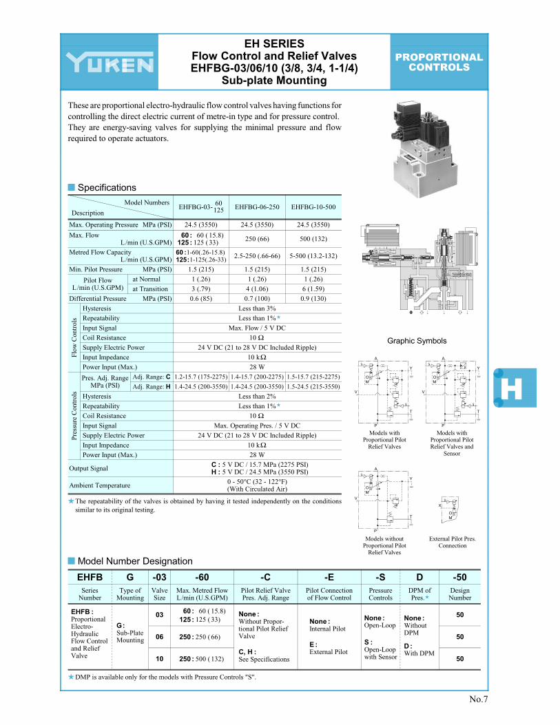
EH SERIES Flow Control and Relief Valves EHFBG-03/06/10 (3/8, 3/4, 1-1/4)
Sub-plate Mounting
These are proportional electro-hydraulic flow control valves having functions for controlling the direct electric current of metre-in type and for pressure control. They are energy-saving valves for supplying the minimal pressure and flow required to operate actuators.
Specifications
The repeatability of the valves is obtained by having it tested independently on the conditions similar to its original testing.
Model Number Designation
DMP is available only for the models with Pressure Controls "S".
No.7

PROPORTIONALCONTROLS
Model Numbers
Description
Supply Electric Power
Input Impedance
Power Input (Max.)
EHDFG
Series Number
-01 -30 -30
Valve Size Rated Flow L/min (U.S.GPM)
Metre-in ·Metre-out
XY :
Design Number
30
EHDFG-01
Max. Operating Pressure
01
03 30
MPa (PSI)
Hysteresis
Repeatability
Frequency Response
Coil Resistance
Ambient Temperature
Proportional Electro-Hydraulic Directional and Flow Control Valve (Sub-Plate Mounting)
EHDFG:
-E
Direction of Flow
Metre-inX :
60 (15.9)60 :
EHDFG-03
Max. Tank Line Back Pres. MPa (PSI)
Rated Flow L/min (U.S.GPM)[Valve P 6.9 MPa (1000 PSI)]
24.5 (3550)
7 (1020)
24.5 (3550)
7 (1020)
30 (7.92) 60 (15.9)
Less than 5%
Less than 1%
Ω
Input Voltage
20 (-90 deg.) Hz
10.5 Ω17 (-90 deg.) Hz
8.0
24 V DC (21 to 28 V DC Included Ripple)
0 - 50°C (32 - 122°F) (With Circulated Air)
10 k
40 W
Ω 10 k
45 W
Ω
1 - 2 k Volume RangeΩBy Controlling Variable
Resistance (Using of Power from Amp.)
By Controlling Voltage (Using of Power outside Amp.)
0 ~ -5 V for SOL a 0 ~ +5 V for SOL b
30 (7.92)30 :
Metre-outY:
-3C2
Spool Type
3C40
3C2
Graphic Symbols
Metre-in • Metre-out Control
3C2 3C40
3C2 3C40
3C2 3C40
A B
a b
P T
A B
a b
P T
A B
a b
P T
A B
a b
P T
A B
a b
P T
A B
a b
P T
Metre-out Control
Metre-in Control
EH SERIES Directional and Flow Control Valves
EHDFG-01/03 (1/8, 3/8) Sub-plate Mounting
These valves incorporate two control functions - flow and direction - which simplify the hydraulic circuit composition and therefore the cost of the system is reduced.
Specifications
The repeatability of the valves is obtained by having it tested independently on the con-ditions similar to its original testing.
Model Number Designation
No.8
Spool type shown in the column is for the centre position.

PROPORTIONALCONTROLS
H
Model Numbers
Description
Supply Electric Power
Input Signal
Input Impedance
Power Input (Max.)
EHDFG
Series Number
-04 -130 -10Valve Size
Rated Flow L/min (U.S.GPM)
Design Number
10
EHDFG-04
Max. Operating Pres.
04
06 10
MPa (PSI)
Hysteresis
Repeatability
Frequency Response
Coil Resistance
Ambient Temperature
Proportional Electro- Hydraulic Directional and Flow Control Valve (Sub-Plate Mounting)
EHDFG:
280 (73.9)280 :
EHDFG-06
Rated Flow L/min (U.S.GPM)Valve Pres. Difference: 1.5 MPa (215 PSI)
15.7 (2275)
130 (34.3) 280 (73.9)
Less than 1%
Less than 1%
Ω55 Hz (-90 deg.)
30 Ω45 Hz (-90 deg.)
30
±24 V DC (±21 to ±28 V DC Included Ripple)
0 - 50°C (32 - 122°F) (With Circulated Air)
10 k
20 W
Ω 10 k
20 W
Ω
130 (34.3)130 :
-2
Spool Type
40
2
15.7 (2275)
Min. Required Pilot Pres. MPa (PSI) 1.5 (215)
2 (.53)
6 (1.59)
0.1 (15)
1.5 (215)
2 (.53)
10 (2.64)
0.1 (15)
at Normal
at TransitionMin. Required Pilot Flow
L/min (U.S.GPM)
Max. Drain Line Back Pres. MPa (PSI)
Rated Flow / ±5 V DC
Alarm Signal Output (Open Collector)
LVDT Output (Sensor Monitor)
Voltage: Max. 30 V DC Current: Max. 30 mA
±5 V DC / Rated Travel of Spool
-EPilot
Connection
Internal PilotNone :
External PilotE :
-D
DPM
Without DPMNone :
With DPMD :
-CBRelief Type Pres.
Compensator
Not ProvidedNone :
ProvidedCB:
Graphic Symbols
Models without Pressure Compensator Valve
Internal PilotAB V P T W Y
AB V P T W Y X
AB P T W Y
External Pilot
Models with Pressure Compensator Valve
Internal Pilot
EH SERIES High Response Type
Directional and Flow Control Valves EHDFG-04/06 (1/2, 3/4)
Sub-plate Mounting
These valves pursue the ultimate performance of proportional electro-hydraulic directional & flow control valves and make themselves to have high response features. The closed-loop is composed in the valve inside by combination of a differential transformer (LVDT) and a power amplifier. Thus, high accu-racy and reliability are provided. In addition to control in the open-loop, these can be used for the closed-loop system as simplified servo valves.
Specifications
The repeatability of the valves is obtained by having it tested independently on the con-ditions similar to its original testing.
Model Number Designation
Spool type shown in the column is for the centre position.
No.9


