
Earthing in railway installations Jernbaneverket Technical Railway Technology
Øyvind Stensby, 5 February 2016

Outline of this presentation
• Introduction to electrified railways and the various overhead
contact line systems
• Legislation – Acts, regulations, TSIs and standards
• Some important regulatory requirements
• Hazard identification – what particular factors do we have to
deal with on electrified railways?
We list 7 situations
• Review of hazards 1–7
1–3 slides for each hazard
• Brief description of the interface between the railway's return
circuit and the network companies' earthing systems
• New Technical Regulations

Electrified railways

Electrified railways – Running rails
• Return route for current from trains
• Reference potential for equalisations
• Earth electrode
• Train detection
• Rails must also have certain mechanical properties in order
to withstand the forces exerted by trains.

Overhead contact line systems
Simple overhead contact line system
Draining transformer system with return in running rails

More overhead contact line systems
Draining transformer with return-current conductor
Autotransformer system with PL, NL and segmented overhead contact line system

What governs us?
Laws:
•Act relating to the inspection of electrical appliances and equipment (Electrical Inspection Act)
•Act on the establishment and operation of railways, including tramways, underground railways and suburban railways, etc. (Railways Act)
Regulations
•Regulations relating to electrical supply installations (FEF)
•Regulations relating to low voltage electrical installations (FEL)
•Regulations relating to interoperability of the railway system (Interoperability Regulations)
•Technical specifications for interoperability (TSIs)
Standards
•NEK 900 (EN 50122-1)
•NEK 440
•NEK 400
Company requirements
•NNRA (Norwegian National Rail Administration): Technical Regulations

An important regulatory requirement
Section 8-6 of FEF
Systems must be designed to ensure that available differences
in potential, touch voltage, earth leakage current and current in
earthing conductors do not represent a risk of personal injury
or damage to equipment or material.
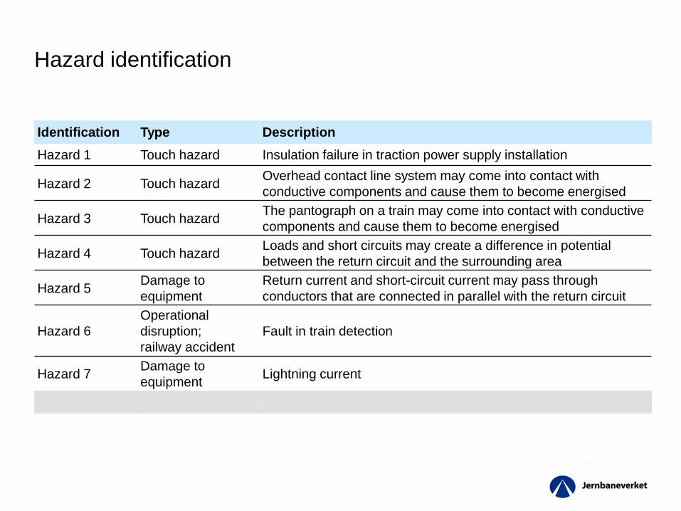
Hazard identification
Identification Type Description
Hazard 1 Touch hazard Insulation failure in traction power supply installation
Hazard 2 Touch hazard Overhead contact line system may come into contact with
conductive components and cause them to become energised
Hazard 3 Touch hazard The pantograph on a train may come into contact with conductive
components and cause them to become energised
Hazard 4 Touch hazard Loads and short circuits may create a difference in potential
between the return circuit and the surrounding area
Hazard 5 Damage to
equipment
Return current and short-circuit current may pass through
conductors that are connected in parallel with the return circuit
Hazard 6
Operational
disruption;
railway accident
Fault in train detection
Hazard 7 Damage to
equipment Lightning current

Hazard 1: Insulation failure in
traction power supply
This hazard is managed by equalising all
exposed conductive components to the return
circuit.
All short circuits occurring as a result of the
insulation failure will then go directly to the
return circuit:
• touch voltage is minimised
• fault is detected by the protection equipment
and results in (almost) immediate
disconnection of the fault.

Hazards 2 and 3: Overhead
contact line and live
pantograph in contact with
conductive components
EN 50122-1:
'overhead contact line zone': the risk zone into
which the overhead contact line can fall
'pantograph zone': the risk zone into which a
live pantograph can stray in the event of a fault

Hazards 2 and 3: Conductive
components in the 'overhead contact line
zone' and in the 'pantograph zone'
Conductive components that are in the 'overhead contact line
zone' and the 'pantograph zone' must be protected so as to
prevent any danger to people from energisations resulting from
fallen overhead contact line or pantographs.
Normal protection: Equalisation to return circuit
Where this is not practical, other measures may be considered
instead:
• Barriers
• Protective screen connected to return circuit
• Locating out of range
• Restricting access

Hazard 4: Increase in potential in return circuit

Hazard 4 – Increase in potential in return
circuit
Available permitted touch voltage is stipulated in NEK 900:
Duration up to 5 minutes: 65 V
Duration up to 0.3 seconds: 480 V
Duration up to 0.1 seconds: 785 V
This can be managed by:
• demonstrating that touch voltage arising from potential
increase in the return circuit does not exceed the
requirements (calculations, measurements)
• implementing measures to limit the danger arising from
voltage increase in the return circuit

Hazard 4
Protection against return potential
• Use of equalisations
• Use of barriers
• Insulating standing surface from earth (e.g.
dry gravel)
• Locating outside range
• Locating conductive components connected
to the return circuit at arm's length from other
conductive components
• Use of access control (trained personnel)
• Reduction of return potential by improving
earth connections

Hazard 4 – About earth electrodes
Running rails are extremely good earth connections in
themselves. As a worst-case scenario, the following
resistances have been calculated:
Frequency
Hz Impedance
ohm
Impedance (3 km)
ohm
16.7 2.5 35
50 4.0 35
Elements such as mast foundations that have been connected
reduce resistance even further
Extra earth electrodes will only affect the resistance against
true earth to a limited degree
• It is not usually expedient to have extra earth electrodes

Hazard 5
Current in conductors parallel
to the return circuit
Thermal heating as a consequence of current
in lineside conductive components
• Fences and crash barriers
• Handrails
• Water pipes and district heating pipes
• Cable guards
• Earthing conductors and neutral conductors
for low-voltage network
If the component has been designed to take
the current, this can be equalised to the return
circuit at several points.
If the component has not been designed to
take the current, there must be segmentation
between each connection point.
Hazards resulting from a voltage
difference at segmentation points or from
disconnection must be assessed.
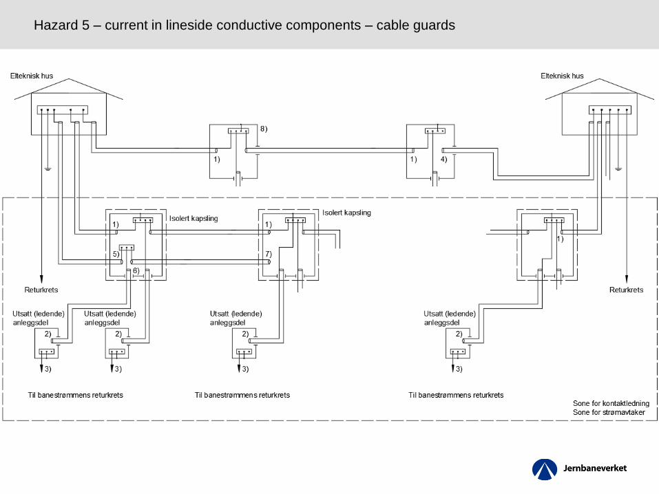
Hazard 5 – current in lineside conductive components – cable guards

Hazard 5 – current in lineside conductive components – low-voltage network

Hazard 6
Disruption to train detection
Train detection systems used by Jernbaneverket:
• Axle counters
• Track circuits
Double-insulated 95/105 Hz
Single-insulated 95/105 Hz
TI 21 audio-frequency track circuit (2–4 kHz)
FTG-S audio-frequency track circuit (4–17 kHz)
Level crossings: 10/50 kHz

Hazard 6 – track circuits – double-insulated 95/105 Hz
Possible solutions:
• Equalisation via filter impedance
• Use of lineside earthing conductors
• Equalisation via voltage limiting devices (VLD, NEK 900)
• Insulation of equalised components from earth

Hazard 6 – track circuits
Earthing system and return current
must not be configured so that a rail
fracture can result in a safety failure.
This is a hazard if a rail fracture
occurs in stations, and for this reason
Jernbaneverket is preparing separate
requirements for the design of return
circuits in stations.
The example is one of three permitted
principle solutions for stations with
double-insulated track circuits.

Hazard 7: Lightning current
Lightning current is diverted to the return circuit via surge arresters
This leads to a high increase in potential, and can break down the
insulation in cables and conductors and start fires.
• Signalling systems are vulnerable
Measures to improve the immunity of vulnerable systems:
• use of isolation transformers for conductors connected to running rails
• length limits for cables connected to running rails
• potential equalisation of cable guards and equipment for running rails
Measures to reduce emissions from surge arresters:
• install impulse electrodes at surge arresters
• connect surge arresters to return circuit via a large high-frequency
impedance:
filter impedance
expedient configuration and connections

Interface between return circuit and
network company earthing system
When components are connected, the following hazards may arise:
• Hazard 4: The potential from the return circuit can be transferred
to the network company's earthing system.
This hazard is normally manageable
• Hazard 5: Where there are connections in several locations
between the network company's earthing system and return
circuit, the return current will go through the earthing system.
This hazard is manageable by ensuring that the design of the
earthing conductors is adequate
The most practical solution is often to separate the return circuit from
the network company's earthing system, but:
• Connection is permitted provided that agreement has been
reached with the relevant network company about how to handle
the hazard (NEK 900)

New Technical Regulations
Jernbaneverket's Technical Regulations for earthing contain
requirements on how to handle the particular challenges posed
by earthing on railway installations.
A complete revision of the Regulations has been published:
https://trv.jbv.no/wiki/Felles_elektro/Prosjektering_og_bygging/Jording_og_utjevning

Technical Regulations – what's new?
• Focus on hazards and risk assessments
• Less focus on specific methods
• Measures are to be used only if they are needed to manage the
hazards. The use of measures must be justified
This means:
• Fewer earth connections and equalising connections than before
• More use of alternative protective measures
• Less focus on 'checking' where the return current goes
It also means:
• Greater need to calculate available voltage differences on specific
sections
• More use of NEK 900 and NEK 440
Calculation assumptions are specified in the standards

Risk assessment
Regulations relating to electrical supply installations, section 2-2:
A risk assessment shall be carried out in order to identify risks in, and
in relation to, the electrical installation. The risk assessment shall
then be used as a basis for the choice of solution to address these
risks. This shall be documented.
• Jernbaneverket therefore expects all solutions chosen for projects
to be on the basis of a documented risk assessment.
• Choosing solutions in accordance with selected standards and the
Technical Regulations is regarded as a sufficient risk assessment.
Where standards and the Technical Regulations indicate a
number of solutions, the reason behind the choice must be
documented

Thank you for your attention


