d .
TECHNICAL REPORT STANDARD TInE PAGE
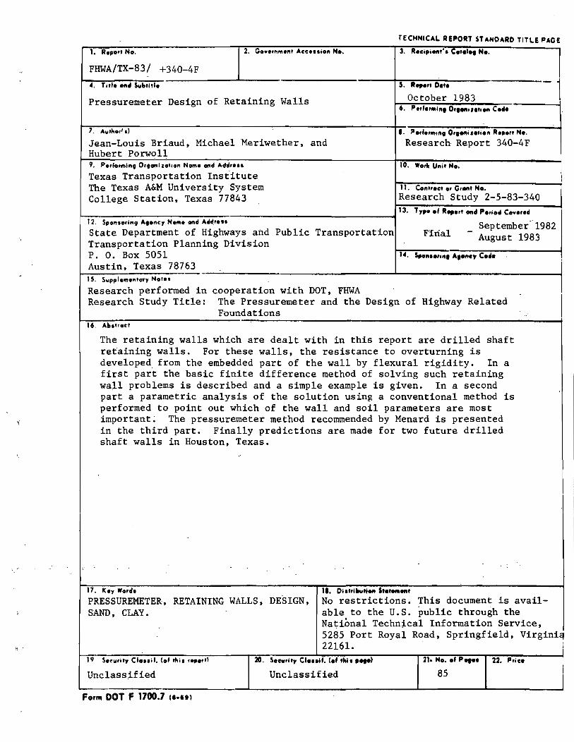
1. R.p." N •. 2. G .... ,n",."' Ace ... i." N ••
FHWA/TX-83/ +340-4F
4. Ti" •• " .. Sult,j".
Pressuremeter Design of Retaining Walls
7. Aulho,1 sl
Jean-Louis Briaud. Michael ~eriwether. and Hubert Porwoll 9. P.,fo,ming Orgonj lol,on Nom. ond Addr ...
Texas Transportation Institute The Texas A&M University System College Station. Texas 77843
3. R.cipieft'·. C.,.I., N ••
5. R ... "D.t.
October 1983 6. P.,f.'IIII", O,fO/t"."eft Coft
e. ".,f.",,,", O"Ofti I.ti." R.po" H ••
Research Report 340-4F
10. Worle Uni' N ••
11. Cont,.ct 0' Gr.nt No. Research Study 2~5-83-340 13. T,p •• f " ... ,t ..... P.,iod Co".r.cI
~~----------~--~~------------~------------~ 12. Spanso,ing Agone, Nome ond Add,... _ September-1982 State Department of Highways and Public Transportation Ffri~l August 1983 Transportation Planning Division P. O. Box 5051 Austin. Texas 78763
14. Spo",.,in, A,eney C.4 •.
1
15. Suppl.",entary NOI.' -------------.------------------~----------------------~ Research performed in cooperation with DOT. FHWA Research Study Title: The Pressuremeter and the Design of Highway Related
Foundations 16. AIt.troc'
The retaining walls which are dealt with in this report are drilled shaft retaining walls. For these walls. the resistance to overturning is developed. from the embedded part of the wall by flexural rigidity. In a first part the basic finite difference method of solving such retaining wall problems is described and a simple example is given. In a second part a parametric analysis of the solution using a conventional method is performed to point out which of the wall and soil parameters are most important~ The pressuremeter method recommended by Menard is presented in the third part. Finally predictions are made for two future drilled shaft walls in Houston. Texas.
17. K.y Wo,cI. 11. Diat,Ututi.eft St.t_ ....
PRESSUREMETER. RETAINING WALLS. DESIGN. SAND. CLAY.
No restrictions. This document is available to the U.S. public through the National Techn~cal Information Service. 5285 Port Royal Road. Springfield, Virgini~
19 S."urity CI ... if, (of IfIi. r.,.,,)
Unclass~fied
Form DOT F 1700.7 II.UI
22161. 20. Securily CI ... If. (.f thi. , ... ,
Unclassified
J 21. N ••• f p .... 22. P,ic.
85

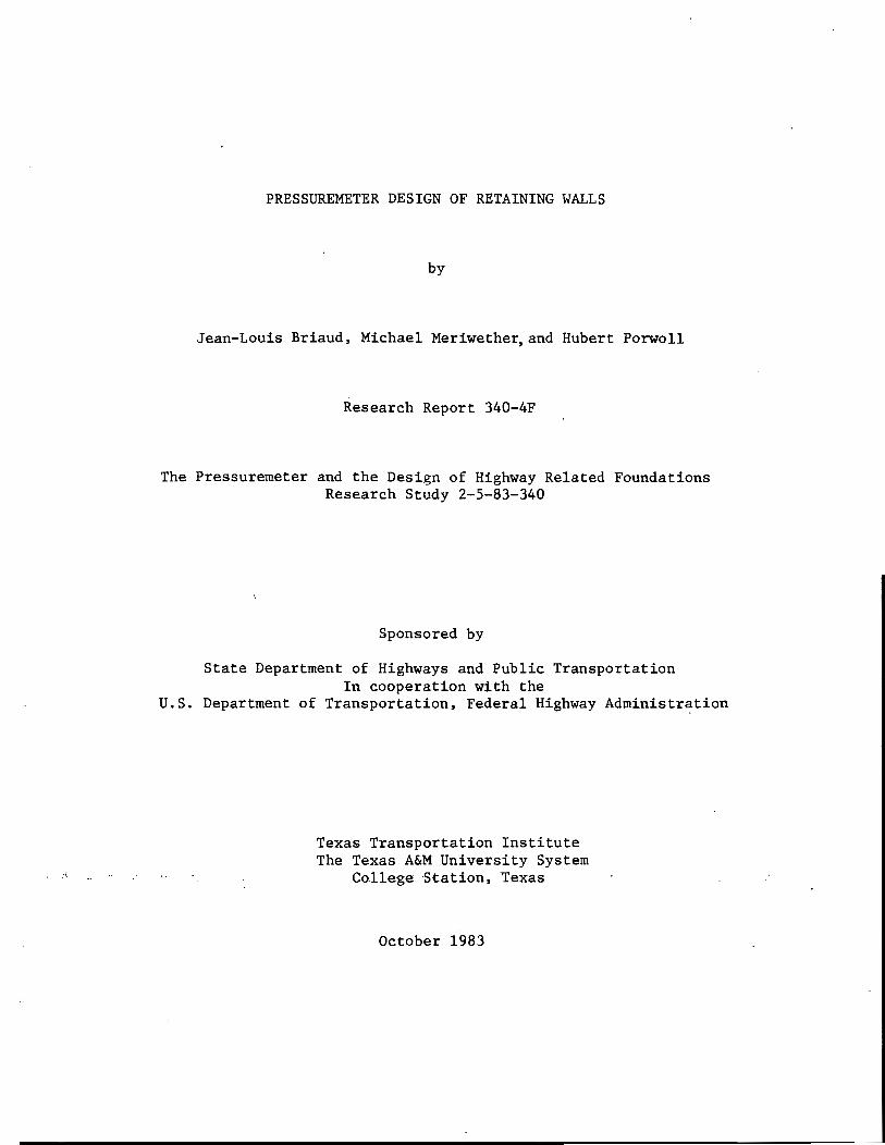
PRESSUREMETER DESIGN OF RETAINING WALLS
by
Jean-Louis Briaud, Michael Meriwether,and Hubert Porwo11
Research Report 340-4F
The Pressuremeter and the Design of Highway Related Foundations Research Study 2-5-83-340
Sponsored by
State Department of Highways and Public Transportation In cooperation with the
U.S. Department of Transportation, Federal Highway Administration
Texas Transportation Institute The Texas A&M University System
. College ·Station,Texas
October 1983


SUMMARY.
The retaining walls which are dealt with in this report are
drilled shaft retaining walls. For these walls the resistance to
overturning is developed from the embedded part of the wall by
flexural rigidity. In this study an assessment of the existing
pressuremeter method for the design of such walls is attempted.
In a first part the finite difference p-y method .to solve such
problems is described and a simple example is given to clarify the
steps followed by the computer program.
i
In a second part a conventional method is described which
consists of using an elastic plastic p-y curve model using the active
and passive earth pressure coefficients. A parametric analysis of
the solution using the above method is performed,and it is shown that
the pile flexural rigidity and the soil friction angle are two of the
most influencial parameters.
In a third part the method proposed by Menard is presented. This
method is based on the use of the pressuremeter modulus and- the
pressuremeter limit pressure to generate the p-y curves for the
embedded part of the wall.
In a fourth part, two case histories of drilled shaft walls in
Houston, Texas,are reported. The two drilled shaft walls are not yet
'built but pressuremeter tests were performed at the sites and
behavior predictions are presented.

ii
ACKNOWLEDGMENTS
The authors are grateful for the continued support and encourage-
. ment of Mr. George Odom of the Texas State Department of Highways and
Public Transportation.
DISCLAIMER
. ,The contents of this report. reflect the views of theauthoTI;'Who are responsible for the opinions, findings, and conclusions presented herein. The contents do not necessarily reflect the official views of policies of the Federal Highway Administration or the State Department of Highways and Public Transportation. This report does not constitute a standard, a specification, or a regulation.
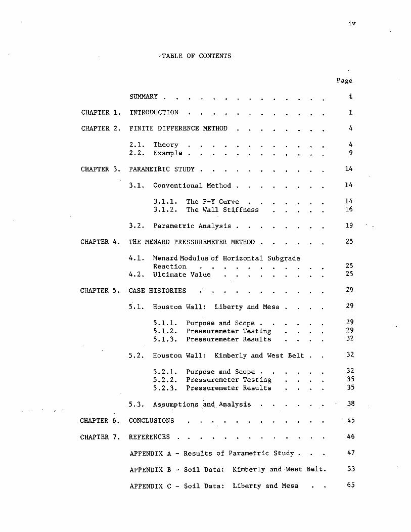
-TABLE OF CONTENTS
SUMMARY .
CHAPTER 1. INTRODUCTION
CHAPTER 2. FINITE DIFFERENCE METHOD
2.1. 2.2.
Theory Example .
CHAPTER 3. PARAMETRIC STUDY •
3.1. Conventional Method
3.1.1. 3.1.2.
The P-Y Curve The Wall Stiffness
3.2. Parametric Analysis .
CHAPTER 4. THE MENARD PRESSUREMETER METHOD .
..
4.1. Menard Modulus of Horizontal Subgrade Reaction
4.2. Ultimate Value
CHAPTER 5. CASE HISTORIES
5.1. Houston Wall: Liberty and Mesa.
5.1.1. 5.1.2. 5.1.3.
Purpose and Scope . Pressuremeter Testing Pressuremeter Results
5.2. Houston Wall: Kimberly and West Belt
5.2.1. 5.2.2. 5.2.3.
Purpose and Scope . Pressuremeter Testing Pressuremeter Results
5.3 .. As.sumptions.and, Analysis
CHAPTER 6. CONCLUSIONS
CHAPTER 7. REFERENCES
APPENDIX A - Results of Parametric Study
iv
Page
i
1
4
4 9
14
14
14 16
19
25
25 25
29
29
29 29 32
32
32 35 35
38
45
46
47
APPENDIX B - Soil Data: Kimberly and ·West Belt. 53
APPENDIX C - Soil Data: Liberty and Mesa 65
iii
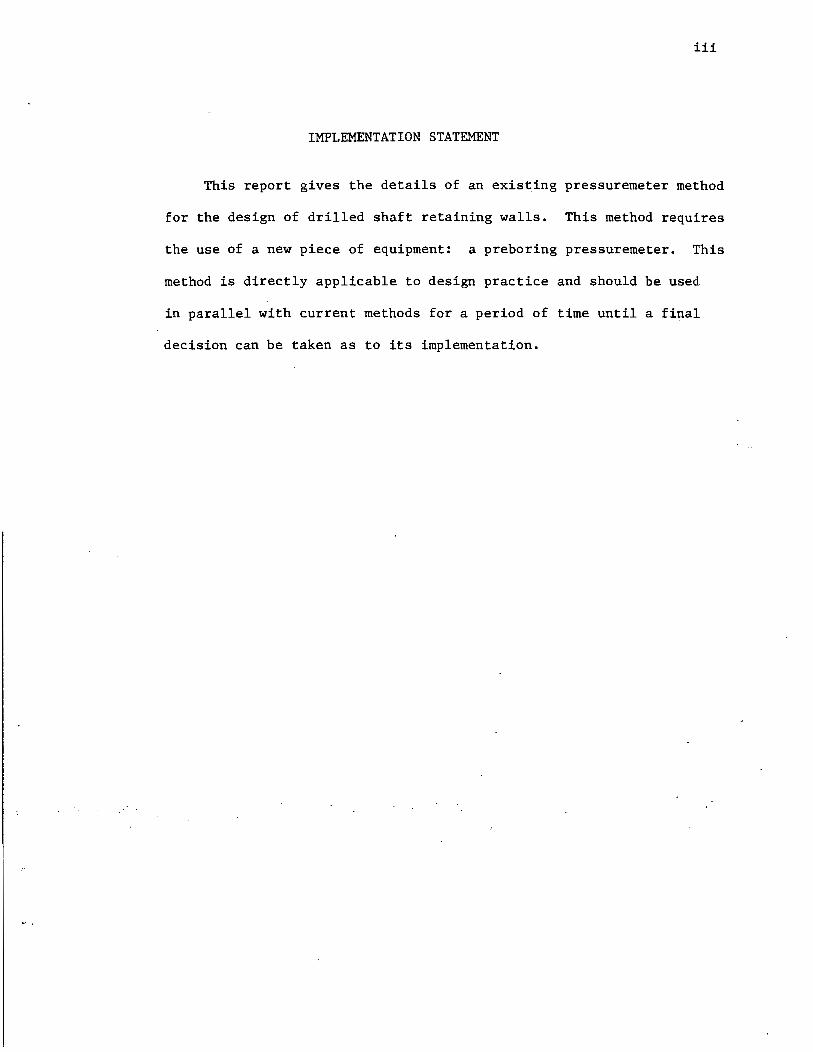
IMPLEMENTATION STATEMENT
This report gives the details of an existing pressuremeter method
for the design of drilled shaft retaining walls. This method requires
the use of a new piece of equipment: a preboring pressuremeter. This
method is directly applicable to design practice and should be used
in parallel with current methods for a period of time until a final
decision can be taken as to its implementation.

CHAPTER 1. INTRODUCTION
This study is related to the design of drilled shaft retaining
walls, sheet pile walls, slurry trench walls, and more generally to the
design of walls which develop part or all of the retaining force from
the resistance of the embedded portion of the wall (Fig. 1).
There are various types of methods available to design such
retaining walls. The first type of method which can be used is the
limit equilibrium approach, where the global equilibrium of the wall
is considered; the distribution of soil pressure is assumed to be the
active pressure behind the wall and the passive pressure in front of
the embedded part of the wall multiplied by an appropriate factor of
safety. This method does not predict the deformation of the wall.
The second type of method is the finite element method where the
wall and the soil surrounding the wall are modeled by finite elements.
This method gives the prediction of soil and wall displacements. At
1
the present time, however, this method is rather expensive due to the
large number of elements necessary to model the problem properly and the
associated cost of computer runs.
The third type of method is the finite difference method where the
wall is modeled by a series of elements acted upon by nonlinear spring
models representing the soil reaction. This method gives a prediction of
wall displacement and can be considered as being of intermediate com-"
plexity between the first and second type of method. The nonlinear
springs modeling the soil behavior are described by p-y curves where p
is the pressure on the wall at depth z and y is the displacement of the
wall at the same depthz (Fig. 2). This method is the one which is des
cribed and used throughout this report.
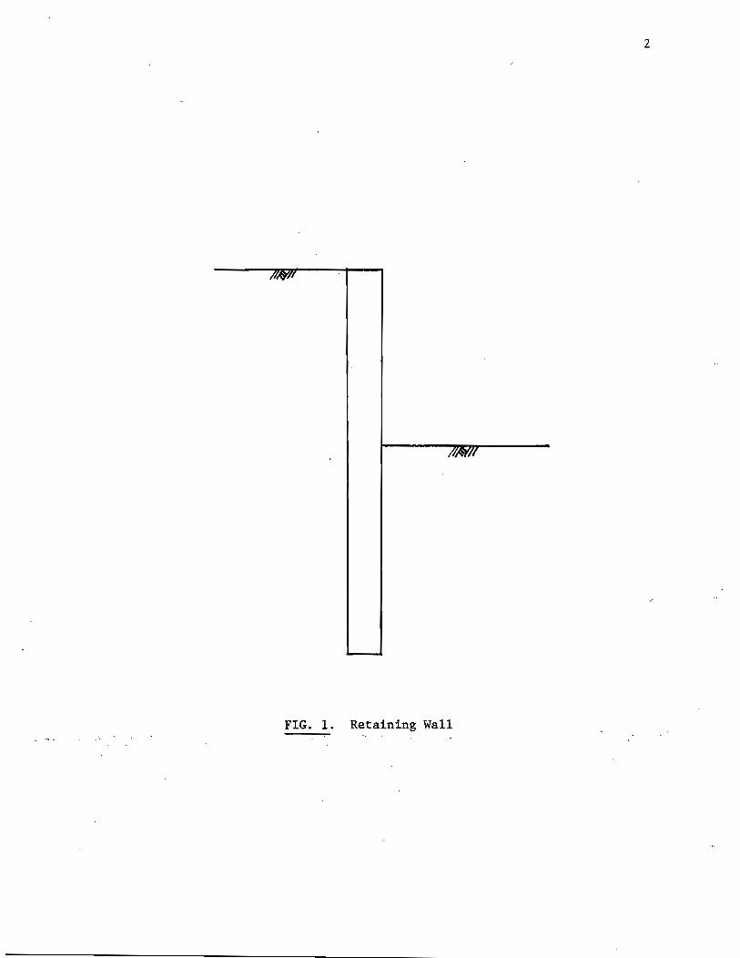
2
/II/Y/I
//NII
FIG. 1. Retaining Wall
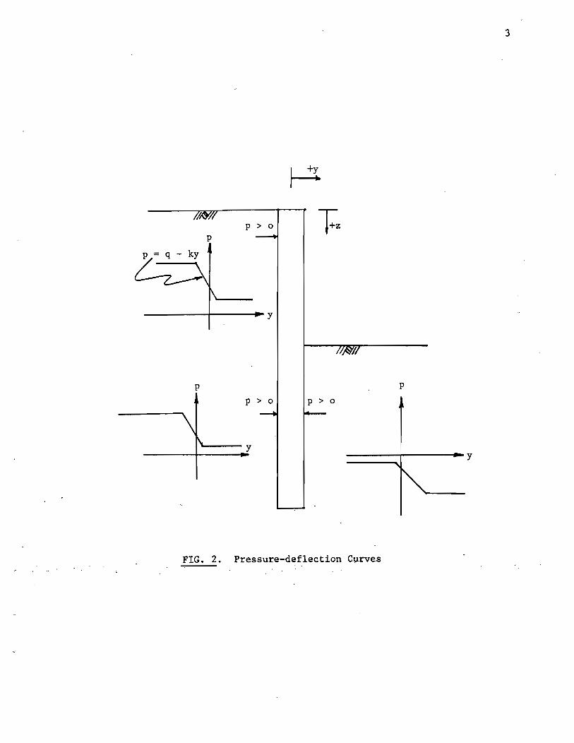
3
p > 0
-----+-----I~ Y
p p
p > 0 p > 0
----y -----+----.... y
FIG. 2. Pressure-deflection Curves

----------------------------------------------------------------------------------~

CHAPTER 2. FINITE DIFFERENCE METHOD
2.1 Theory
where
The constitutive equation for the wall in bending is
M = EI<I> 2
= EIU dz
2 . . . . . . . . . . . . . . . . . . .
M = the bending moment at depth z,
E = the modulus of elasticity of the wall,
I = the moment of inertia of the wall for a unit width
4> =
R =
y =
z =
of wall,
2 2 the wall curvature = l/R = d y/dz ,
-the wall radius of curvature,
the wall lateral displacement, and
the depth.
(1)
Considering a unit width of wall, the equilibrium ~quations of a wall
element lead to
where
and
where
thus
dV w = dz . . . . . . . . . . . . . . . .
w = the force per unit length or loading intensity on the
wall,
v = the shear force at depth z,
dM = Qdy + Vdz . • .
Q is the axial load,
. . . . . . . . . . . . . . . . . . . .
(2)
(3)
(4)
The governing equation is obtained by-combining equations 1 and 4:
4

~- ----~-----------------------------------------,
2 2 ~EI ~ + Q ~ - w (y,z) = 0
dz 4 dz2 (5)
Generally there is no axial load Q on the wall and the equation
reduces to:
2 EI ~ - w (y,z) = 0
dz 4 . . . . . . . . . . . . . . . (6)
5
Taking a unit width of wall, soil pressure p can be substituted for
loading intensity since loading intensity is the product of pressure
and width. For simplicity, pressure will be assumed to vary linearly
with deflection resulting in the expression (Fig. 2)
p = q - ky
where q = the pressure at zero deflection, and
k = the slope of the p-y line.
This gives the equation
q - ky d 2 = .Q...Y
EI 4 dx (7)
When the wall is divided into a number of discrete segments, the
finite difference method can be used to solve this equation.
From finite differences:
(8)
~ _ Yi+2 - 2Yi+l + 2Yi_l - Yi-2
dx3 - 2h3 (9)
(10)
where-Yi = deflection at node i~ and
h = distance between nodes.
Substituting equation (8) into equation (7) gives
or
4 q.h ~ --= EI (11)
For a wall of n nodes. n equations of this form can be written.
6
Since q. h. k, and EI are known for each node, the only unknowns are the
n+4 deflections. The four extra deflections come f~om imaginary nodes:
two above the top node and two below the bottom node of the wall. The
four additional equations required come from boundary conditions.
Shear-and moment are known to be zero at both top and bottom of the wall
and the resulting equations are:
v o
EI = 0
M 0
0 -= E!
V n :In == 0
M .n 0 -=
EI
dZ Yo
=--= dx 2
d3 Yn
=--= dx 3
dZ Yn
= --= dx 2
Yz - 2Yl + 2Y_l - y~z
Zh3
Yl - Zy + Y-l 0
h2
Y - Y + 2y . -.. n+Z n+l .... n-l ..
2h3
Yn+l - 2y + Y 1 n n-
h2
Yn-2
These equations can be rewritten as:
Y2 - 2Y1 + 2Y_1 - Y-2 = 0 . . ~ • • . • • . • . . •• (12)
Y1 - 2y + Y 1 = 0 . . . . . . . . . . . . . . . . .. (13) 0-·
Yn+2 - 2Yn+l + 2Yn_l - Yn- 2 = 0 . . . . . . . . . .. (14)
Y n+ 1 - 2y n + Y n = 0 • • • • • • • • • • • • • • • •• (15)
Collecting equations gives
h4 k h4 qn ----EI = Yn+2 - 4Yn+1 + (6 + nE1 ) Y - 4y 1 + Y 2 n n- n-
o = Y +1 - 2y + Y 1 n n n-
7

8
Rewritihg in matrix form gives
-1 2 0 -2 1 y-i o
1 -2 1 y-l o
k h4 1 -4 6+ 0 -4 1 EI
k h4 1 -4 1 -4 1 6+---
EI Yl
. k h4
1 -4 6+~-4 EI 1
1 -2 1-Yn+l o
-1 2 0 -2 1 o
This method will not work when the wall has infinite stiffness because
the coefficient matrix becomes singular and the solution matrix is
uniformly zero.
This is the method used in the computer program BMCOL7 with the
added feature of being able to handl_e nonlinear expressions for pressure.
BMCOL7 uses the iterative technique to handle nonlinear expressions for
pressure. To do this, pressure-deflection curves are simplified into a
number of straight line segments and the coordinates of each segment end
point are entered into the program. Starting with zero deflection, q
- and k are computed for each node._ Where no p,..y curve has been input,. 'the
program interpolates to find a curve! Next, the program runs through
the finite difference method and computes deflections. If-these deflec-
tions differ sufficiently from the previous ones, another iteration must
be done. Using the new deflections, q and k are recalculated from the
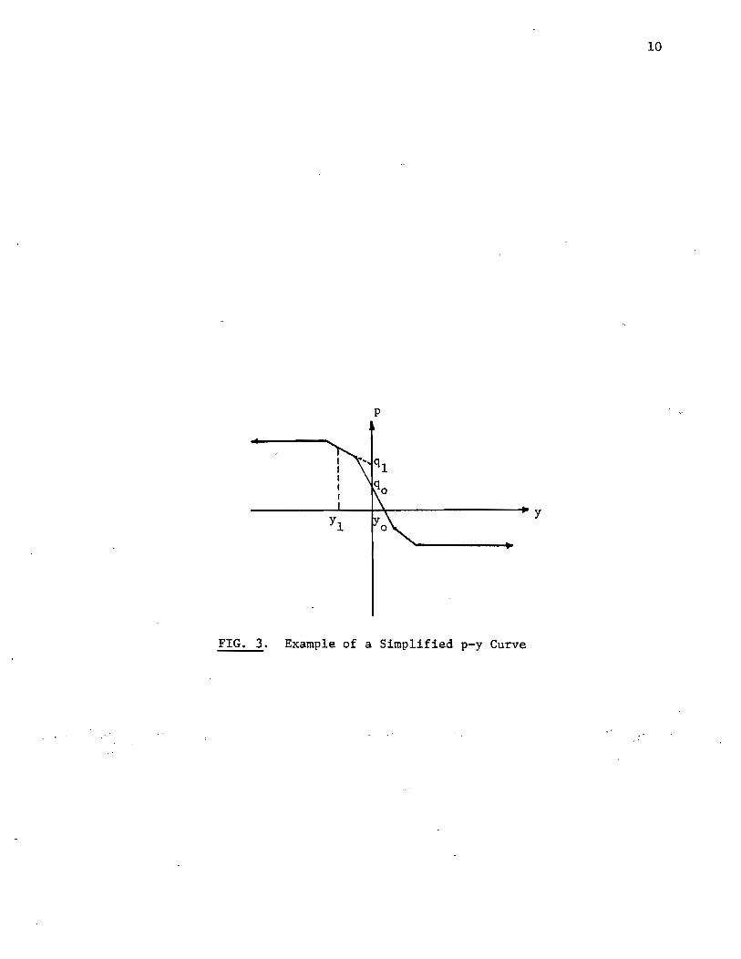
p-y curve. K is the slope of the curve and q is the pressure found by
extending the tangent to the curve back to where it intercepts the
p-axis (Fig. 3).
The iteration process is continued until it closes on the correct
deflection for each node. BMCOL7 then uses the deflections to compute
the slope, moment, shear, and reaction at each node.
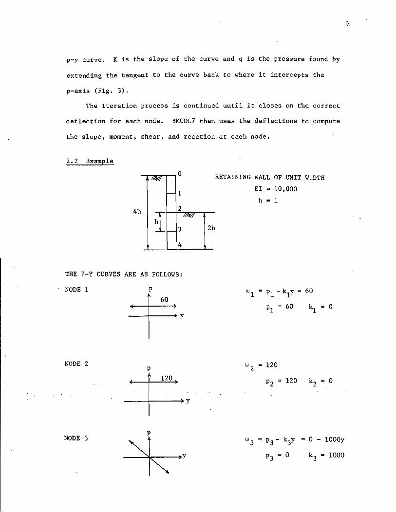
2.2 Example
--.-.............. --.0
1
4h 2
3
4
THE P-Y CURVES ARE AS FOLLOWS:
NODE 1 p
60
-_-+-----10 Y
NODE 2 p
120
----I---~y
NODE 3 p
--~~--.,.y
RETAINING WALL OF UNIT WIDTH
EI = 10,000
2h
h = 1
w = p - k y = 60 III
PI = 60 kl = 0
w 2 = 120
P2 = 120 k2 = 0
= 0 - 1000y
k3 = 1000
9
10
p
__________ L-~~---------------.y
FIG. 3. Example of a Simplified p-y Curve

"
P
NODE 4 w 4 = P 4 - k4y = 0 - 1500y
------~------~y P = 0 4
THERE ARE NO PRESSURES AT NODE 0 SO P = k = 0 o 0
BY OBSERVATION Vo = Mo = V4 = M4 = 0
SET UP THE SET OF EQUATIONS IN MATRIX FORM
-1 2 0 -2 1 0 0 0
0 1 -2 1 0 0 0 0
k h4 1 -4 0
6+E'I -4 1 0 0 0
k h4 0 1 -4 1 -4 1 0 0 6+E'I
k h4 0 0 1 -4 2 1 0 6+ ---4 EI
k h4 0 0 0 1 -4 3 1 6+ ---4 EI
k h4 0, 0 0 0 1 '-4,' 6+ _4_'~4
EI
0 0 0 0 0 1 '-2 1
0 0 0 0 -1 2 0 -2
k4 = 1500
r- -0 2V h3
y-2 0
EI
M h2
0 0
y-1 EI
h4 Po
0 Yo EI
4
0 P1h
Yi EI
4
0 P2h
Y2 =
4
0 P3h
Y3 EI
4
1 P4h
Y4 EI
3
0 2V4h
Y5 EI
M h2
1 4 Y6 EI
'- -
11
12
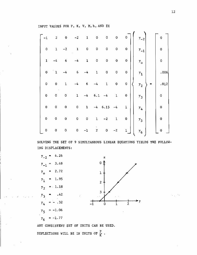
INPUT VALUES FOR P, K, V, M, h, AND EI
-1 2 0 -2 1 0 0 0 0 Y-2 0
0 1 -2 1 0 0 0 0 0 Y-1 0
1 -4 6 -4 1 0 0 0 0 Yo 0
0 1 -4 6 -4 1 0 0 0 Y1 .006
0 0 1 -4 6 -4 1 0 0 Y2 = .012
0 0 0 1 -4 6.1 -4 1 0 Y3 0
0 0 0 0 1 -4 6.15 -4 1 Y4 0
0 0 0 0 0 1 -2 1 0 Y5 0
0 0 0 0 -1 2 0 -2 1 Y6 0
SOLVING THE SET OF 9 SIMULTANEOUS LINEAR EQUATIONS YIELDS THE FOLLOW-
ING DISPLACEMENTS:
Y = 4.26 -:-2 z
Y = -1 3.49
Yo = 2.72
Y1 = 1. 95
Y2 = . 1.18
. Y3 = .. 42 .
Y4 = - .32 o· 2 Y
-1 1
Y5 = -1. 06
Y6 = -1. 77
ANY CONSISTENT SET OF UNITS CAN BE USED.
DEFLECTIONS WILL BE IN UNITS OF i .
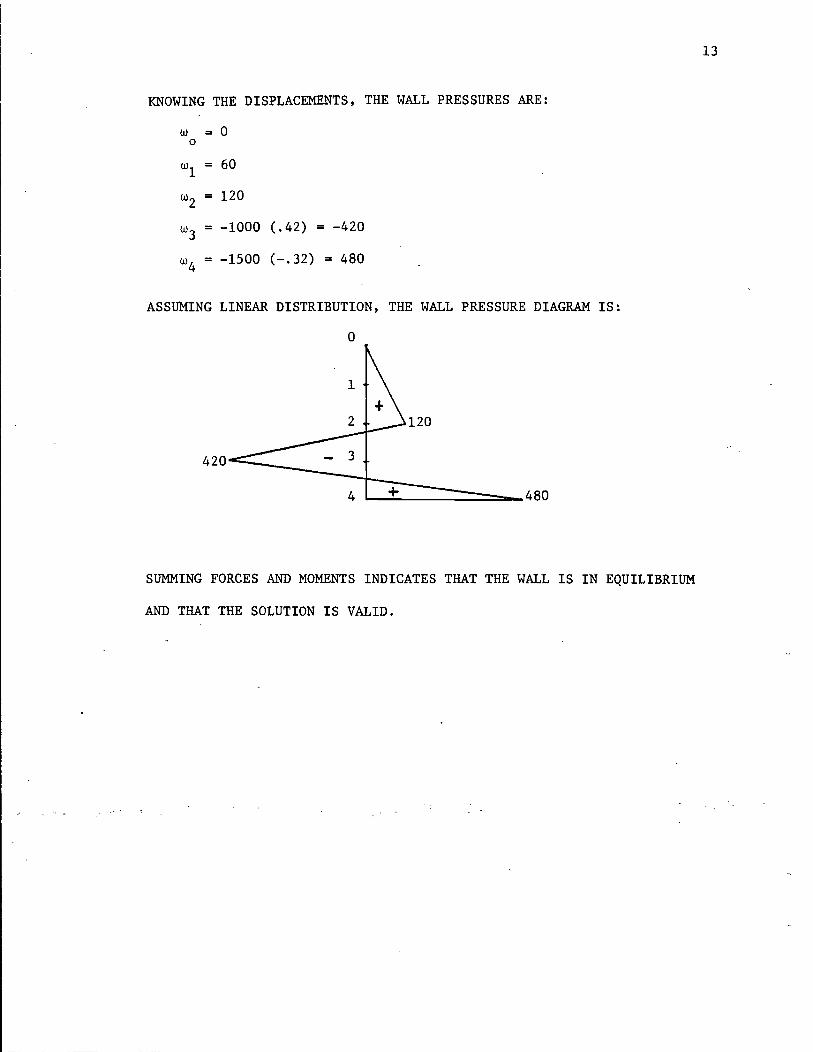
KNOWING THE DISPLACEMENTS, THE WALL PRESSURES ARE:
W = a o
WI = 60
w2 = 120
w3 = -1000 (.42) = -420
w4 = -1500 (-.32) = 480
ASSUMING LINEAR DISTRIBUTION, THE WALL PRESSURE DIAGRAM IS:
o
120
420~ ____ _
4:1=+£:::::::::===-_480
SUMMING FORCES AND MOMENTS INDICATES THAT THE WALL IS IN EQUILIBRIUM
AND THAT THE SOLUTION IS VALID.
<--~~~~~~~~~~~~~---~----------- -- - --------- -------------------------------- -----
13
-- - ----------------------------------------------------.
CHAPTER 3. PARAMETRIC STUDY
3.1 Conventional Method
3.1.1. The P-y Curve
Conventional soil mechanics gives the active, passive, and at
rest soil pressures at a depth, z, as follows for dry conditions:
where
P = K y z active a
P . = Kyz passl.ve p
P = K Y z at rest 0
K a the active soil pressure coefficient,
K = the passive soil pressure coefficient, p
K = the at rest soil pressure coefficient, and o
y = the soil unit weight.
K is assumed to be 0.5. K and K are computed from the angle of o a p
internal friction, cf> •
14
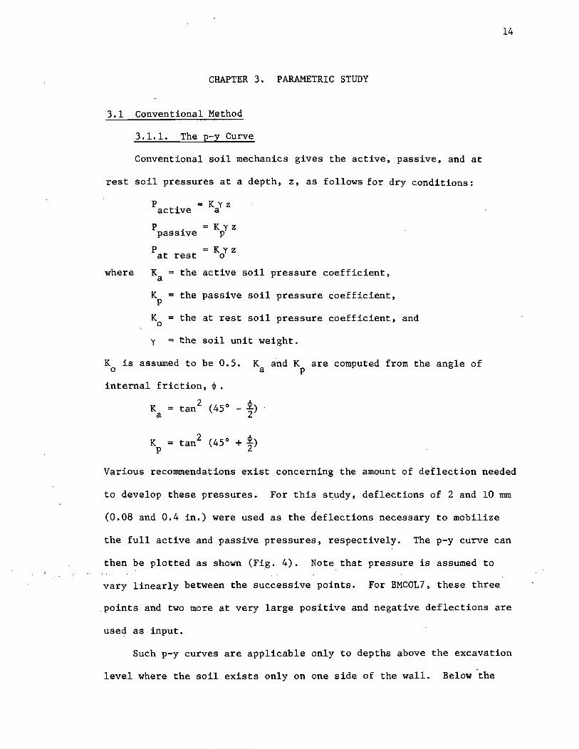
Various recommendations exist concerning the amount of deflection needed
to develop these pressures. For this study, deflections of 2 and 10 mm
(0.08 and 0.4 in.) were used as the deflections necessary to mobilize
the full active and passive pressures, respectively. The p-y curve can
then be plotted as shown (Fig. 4). Note that pressure is assumed to
vary linearly between the successive points. For BMCOL7, these three
points and two more at very large positive and negative deflections are
used as input._
Such p-y curves are applicable only to depths above the excavation
level where the soil exists only on one side of the wall. Below the
P
400 psf
200 psf
From parametric analysis - Case 2 Depth =10 ft
----4-----~--~----~----+---. Y (inches) -.4 -.2 .2 .4
FIG. 4. p-y Curve Above Excavation Level
15

16
excavation level the soil on the other side of the wall must be taken
into account. The method of superposition is used to find these p-y
curves (Fig. 5). Instead of inputting five points, seven p-y values
are now required for BMCOL7.
BMCOL7 does not require the input of a p-y curve at each node
since it interpolates between curves. The number of p-ycurves needed
to get a fair representation of a particular problem is determined by
discontinuities. Obvious discontinuities are the excavation limit,
both ends of the wall, and changes in soil properties.
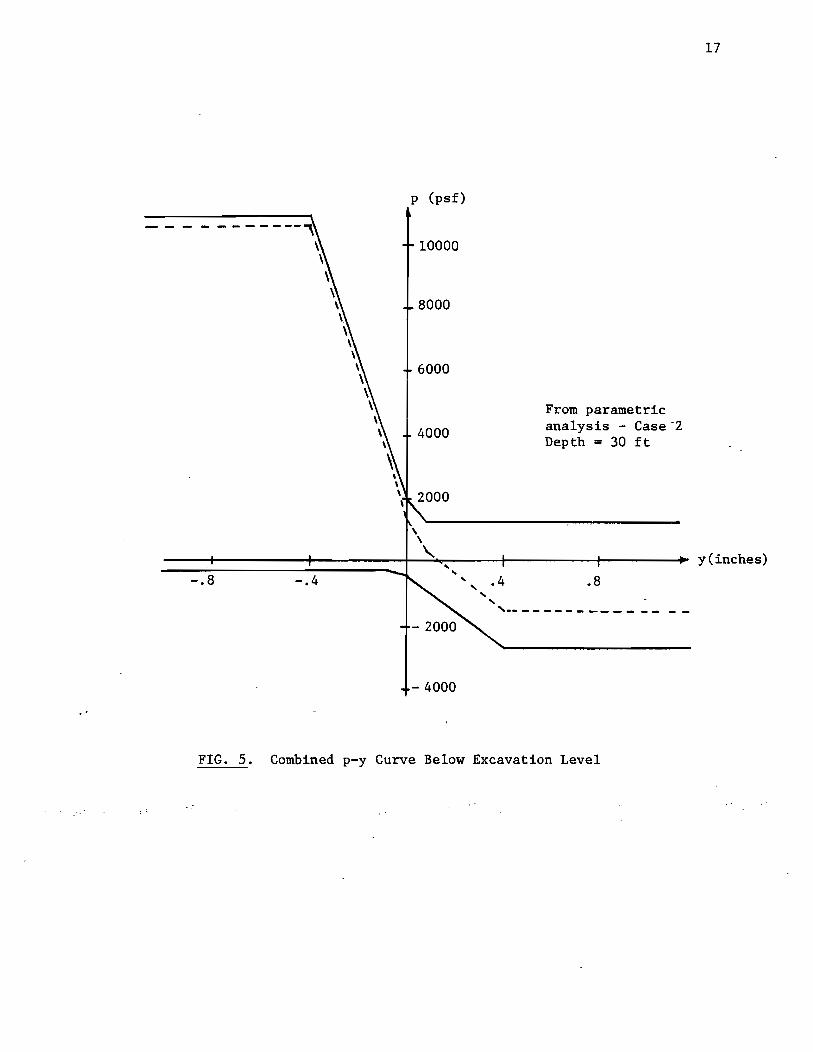
3.1.2 The Wall Stiffness
The stiffness of reinforced concrete retaining walls does not
remain constant, but decreases as loads are applied. This is due to
cracking of the concrete which reduces the moment of inertia. The
American Concrete Institute recommends the use of the gross moment of
inertia until the applied bending moment exceeds the cracking moment.
At this point, the effective moment of inertia should be used (Fig. 6):
where
M
M I = (~)
e M a
3 M
3
I + [1 - ( cr) ] I g M cr
a
I = the effective moment of inertia, e
= cracking moment due to bending, cr
M = the applied bending moment, a
I = the gross mpment of ine~tia, . and g
I = the cr cracked moment of inertia.
Unfortunately, BMCOL7 does not have the capability to compute the
effective moment of inertia. The user can address this problem by
using the iteration method with each computer run being an iteration.
-.8 -.4
p (psf)
10000
8000
6000
4000
, ,
- 4000
From parametric analysis - Case "2 Depth = 30 ft
" .4 .8 .. , ,-- - - - - - - - - - - --
FIG. 5. Combined p-y Curve Below Excavation Level
17
y(inches)
,..... ..;t .
!:l "1"'4 '-'
t1l ..... .j..I
"'" Q)
!:l H
~ 0
.j..I
!:l Q)
= 0 ::El Q)
~ .j..I () Q) ~ ~ I'<l
I gr
20000
15000
10000
5000
o
18
EXAMPLE CURVE FOR 3 FT DIAMETER SHAFT AND 1.75 IN. 2 AREA OF STEEL
0.5 1.0 1.5
Applied Moment (in.-1bs x 10-6)
Ig = 23557 in.4
ICR = 5437 in.4
MCR = .675 x 106
in.-1bs
2.0 M max
FIG. 6. Effective Moment of Inertia vs. Applied Bending Moment

First, a graph of applied bending moment versus effective moment of
inertia is plotted and BMCOL7 is run using a constant EI throughout.
Using the results of this run, an EI value can be obtained from the
Mversus EI plot for each segment of the wall and BMCOL7 is rerun
using the new EI values. This process is repeated until the EI values
input correspond to the values from the M versus EI plot. By guessing
the applied moments and running four or five trials at once, a reason
able answer can be achieved in three iterations. BMCOL7 has the
capability to run many problems at once using the same p-y curves with
a minimal amount of input. Note that when steel sheet piling is used,
EI remains constant up to yielding of the steel.
3.2 Parametric Analysis
A parametric analysis was done on the wall at Liberty and Mesa
19
in Houston with respect to the embedment depth, the wall stiffness,
the soil internal friction angle, and the slope of the soil p-y curve.
This wall is made of 60-foot long, three-foot diameter, drilled shafts
spaced 3.5 feet center to center. The wall has a stiffness of 9.42 x
1010 1b-in. 2 per foot of wall width. The conventional p-y curves
described in the previous section were used with a friction angle of
30°, a unit weight of 120 pcf, and a coefficient of at rest earth
pressure of 0.5. The cases studied are summarized in Table 1. Figure
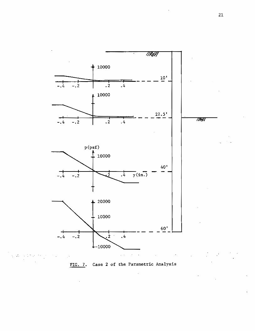
7 shows an example set of -p~y c.ui'les for one of the cases studied.
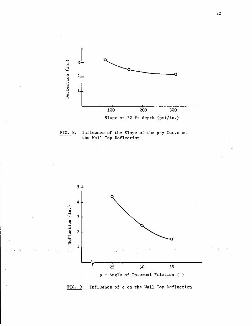
An examination of the results (Fig. 8) shows that the slope of
the p-y curve has a minor effect on the total displacement at the top
of the wall. The reason is that along most of the wall the deflections
are large enough to mobilize the fu1l active and passive resistance of

CASE NO.
1
2
3
4
5
6
7
8
9
10
11
12
13
14
15
16
17
18
19
SOIL WALL
STIFFNESS, EI
SLOPE OF P-Y EMBEDMENT LB-IN~ PER FT FRICTION
'ANGLE, <jl (0) (AT DEPTH = 22') CURVE, K (PSI/IN.) DEPTH (FT) OF WALL LENGTH
25
30
35
30
" 30
TABLE 1:
100
100
100
50
100
200
100
" 100
37.5 ~,
" 37.5
22.5
24
25.5
27
30
37.5
45
48
37.5 ~,
'r 37.5
Summary of Cases Studies
9.42 x 10¹⁰
" 2.68 x 10¹⁰
5.4 x 10¹⁰
9.42 x 10¹⁰
15.4 x 10¹⁰
10 23.35 x 10 .
20
~ 10000. 10'
-+-1 --4F:::::::::::f-=====F· ==;:1 =~- - - - --.4 -.2 .2.4
10000
22.5' -+-.:...-.-+--+:===t===f===- - - - - --.4 -.2 .2 .4
p(psf)
40'
-.4 .4 y(in.)
60' -t-----!I---~:__--tf----+--- - - - - - -
FIG. 7. Case 2 of the Parametric Analysis
21
-. s:: oM '-'
s:: 2 0 -.-I ~ tJ Qj
...-i 1 4-< Qj
,::)
100 200 300
Slope at 22 ft depth (psi/in.)
FIG. 8. Influence of the Slope of the p-y Curve on the Wall Top Deflection
5
4 -. s:: oM '-' 3
s:: 0
-.-I ~ tJ 2 Qj
...-i 4-< Qj
,::)
1
25 30 35
~ - Angle of Internal Friction (0)
FIG. 9. Influence of ~ on the Wall Top Deflection
22

------- ------------------------------------------------------------------------------------,
the soil.
The second soil parameter, the angle of iriternal friction, has
a major effect on the displacement (Fig. 9). The reason is that the
active and passive pressures are directly dependent on the angle of
internal friction: decreasing $ increases the active pressure and
decreases the passive pressure.
23
The effects of the wall properties are shown on Figures 10 and 11.
Common sense indicates that a stiff wall will deflect less than a more
flexible one. The graph of stiffness versus deflection (Fig. 10)
indicates that it is not cost efficient to increase the wall stiffness
beyond a certain value.
Figure 11 illustrates the diminishing effect of increasing the
wall embedment depth •. Beyond a certain point, increasing the embedment
depth has no effect on the wall deflection. The wall is essentially
fixed and the soil pressures on either side of the wall are nearly
equal below the point of fixity.
Varying the stiffness along the cross-section of the wall had a
significant effect on the deflection. To reflect the reduction in
stiffness due to cracking, the wall was tested with the middle third
having a stiffness equal to about one fourth of the regular stiffness.
The maximum deflection was nearly double that of the uncracked wall.
The s·tiffness reduction was based on the ACI code and involved an
assumption of the amount of reinforcing steel present in the wall. The
results are shown in Appendix A as are the detailed results for each
case of the parametric analysis.

7
= 6
5
---. s:: oM
4 '-'
s:: 0
oM .\oJ
3 CJ Q)
.-4 ~ Q) 0 2 = 3.5'
1 Pier dia.
5 10 15 20
EI - x 1010 lb-in. 2 per Foot of Wall Width
FIG. 10. Influence of Wall Stiffness on Wall Top Deflection
5
4
---. s:: oM
3 '-'
s:: 0
oM .\oJ 2 CJ Q) r-! ~ -Q)- -
0 1 Cantilever Height = 22.5'
20 30 40 50
Embedment Depth (ft)
FIG. 11. Influence of Embedment Depth on Wall Top Deflection
24
= 4'
----------------------------------------
L-_________________________________________________________________________________________________________________________________________________________ _

CHAPTER 4. THE MENARD PRESSUREMETER METHOD
4.1 Menard's Modulus of Horizontal Sub grade Reaction
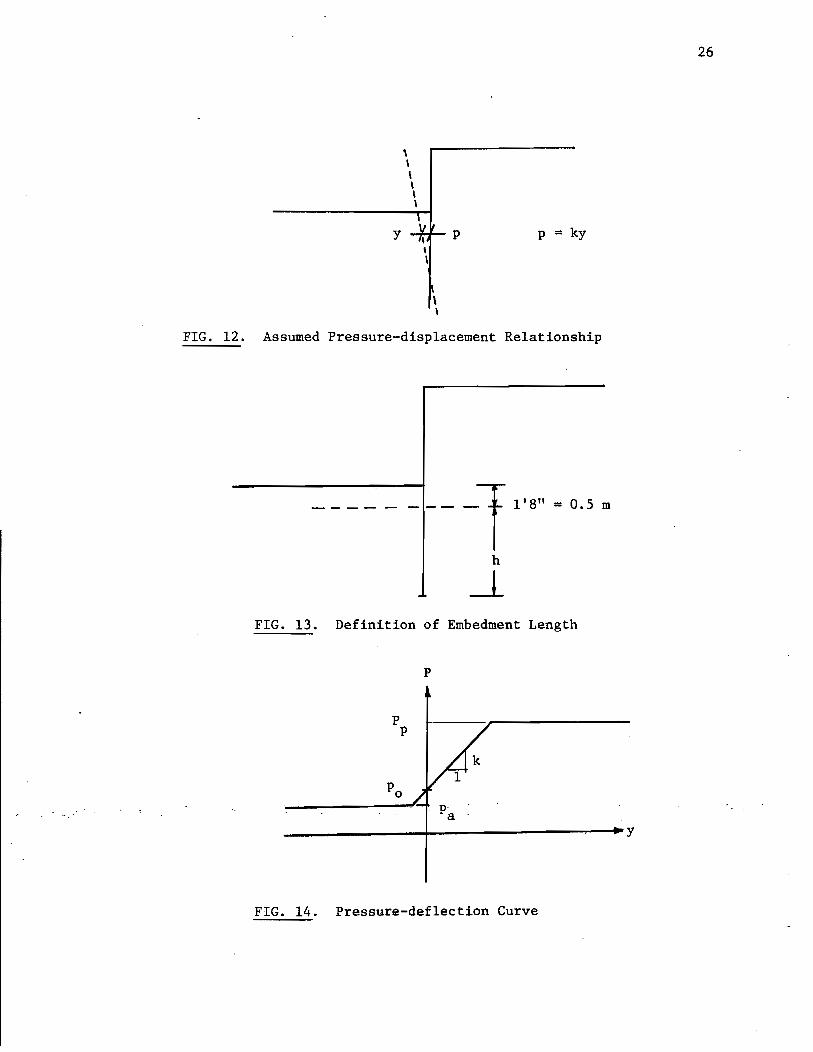
The pressure of the soil on a retaining wall can be assumed to
be proportional to the horizontal displacement of the wall (Fig. 12)
where the constant of proportionality, K, is called the modulus of
horizontal subgrade reaction. A value for K can be found from data
obtained by a pressuremeter, an in situ testing device described in
Chapter 5. Menard (1, 2, 3) gives the following equation for K in
tons per cubic foot for a concrete or sheet-pile wall, below excava-
tion level
1 1 a 13 a K = ~ [2 a + 30.48 (0.09 x 30.48 x a) ]
where ~ = the arithmetic average of the pressuremeter soil modulus
in tons per square foot over the upper two-thirds of the
considered embedded length, h (Fig. 13),
a = two--thirds of h in feet, arid
a = a dimensionless coefficient (Table 2) depending on ~
and on the limit pressure of the pressuremeter test.
It can be seen that this equation is correct from the point of
view of dimensions when a = 1. The coefficient a was introduced by
Menard,in order to match a data set which. he.has not described iIi
the referenced publications.
4.2 Ultimate Value
The modulus of horizontal sub grade reaction, K, is actually the
slope of the p-y curve in the elastic region. In order to get a
25
y
, \ \ \ \ \
\ \
p . p = ky
FIG. 12. Assumed Pressure-displacement Relationship
---- - --- -1 1'8" = 0.5 m
h
J. FIG. 13. Definition of Embedment Length
P P
P
--~---------+--------------~~y
FIG. 14. Pressure-deflection Curve
26

Clay
Degree of E Consolidation - a pR-
Over-consolidated 16 1
Normally 9-16 2/3 Consolidated
Under-consolidated or 9 1/2
Weathered
Silt Sand Sand and Gravel
E E E PR- a
PR- a PR- a
14 2/3 12 1/2 10 1/3
8-14 1/2 7-12 1/3 6-10 1/4
8 1/2 7 1/3 6 1/4
TABLE 2: Recommended a Values
E/pR- 10 15
Clay 2.7 3.2
Sand 3.5 4.2
TABLE 3: Recommended KB Values
Peat Rock
Condition
1 Very Fractured
1 Normally Fractured
Not Fractured 1 or
Very Weathered
a
1/3
1/2
2/3
N ......
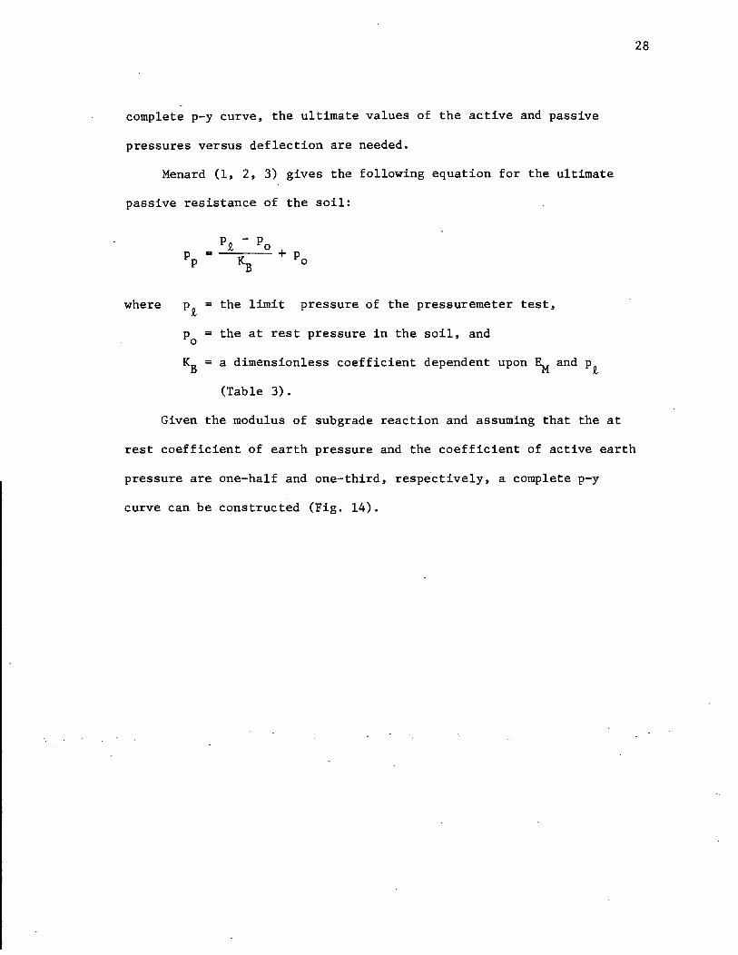
complete p-y curve. the ultimate values of the active and passive
pressures versus deflection are needed.
Menard (1. 2. 3) gives the following equation for the ultimate
passive resistance of the soil:
where p~ = the limit pressure of the pressuremeter test.
Po = the at rest pressure in the soil. and
KB = a dimensionless coefficient dependent upon ~ and P2
(Table 3).
Given the modulus of sub grade reaction and assuming that the at
28
rest coefficient of earth pressure and the coefficient of active earth
pressure are one-half and one-third. respectively. a complete p-y
curve can be constructed (Fig. 14).

CHAPTER 5. CASE HISTORIES
5.1 Houston Wall: Liberty and Mesa
5.1.1 Purpose and Scope
A geotechnical investigation was undertaken as part of the
evaluation of the foundation conditions for the retaining walls of a
railroad underpass. The site is located close to the intersection of
Liberty Road and Mesa Road (FM 527) in Houston, Texas (Fig. 15). Each
retaining wall will be made of a line of drilled piers, 3 feet in dia-
meter with a 42 inches spacing center to center. At the final stage
of construction, those piers will have a total length of 60 feet and
retain 22.5 feet of soil (Fig. 16).
The work consisted of performing pressuremeter tests at the site
in order to obtain the soil properties as follows:
first loading modulus
reload modulus
net limit pressure
A total of eight tests were performed on June 29, 1983.
5.1.2 Pressuremeter Testing
The pressuremeter used was a TEXAM model sold by Roctest, Inc.
This is a monocell pressuremeter inflated with wa~er. The probe is
70 mm in diameter and has an initial deflated volume of 1380 cm3 .
. Ij:ight tests· and two calibrations were ·performed. One of the eight
test boreholes was too large and the results are not reported.
29
All tests were performed in the same boring. The hole was drilled
using rotary drilling with axial injection of prepared mud with a 4
inches drilling bit down to a level located 3 feet above testing level.

FM 527
MESA RD.
FH~J,n.
RAILROAD TRACKS
SHEET PILE WP.lI..
TEXAM P~1T
\
BLADE ____ ' ~ """~ ,.\ ... . J"01 I" "----+_~
VI I
f
/
/
/ SDHPT
SAMPLES
f
. o 0:::
>I-0::: L.&J co ..... ...J
FIG. 15. ~ocation of Pressuremeter Test Hole
30
UNDERPASS

Depth (ft)
o
10
20
30
40
50
o
60 1
Pressuremeter Tests
" o ., o
</>3 1
.~------------~ I •
I · I · r •
I
:. I : ,+,'
---- -T 3 1
____ .-t..
3.5 1
--~
T 22.5 1
37.5 1
.--.0:;--- DRILLED PILES
. FIG. 16. Depths of Pressuremeter Tests
31

For the last 3 feet, a 2-15/16 inches bit was used with a slower
rotation speed and a lower mud pressure. This procedure gave very
satisfactory overall results.
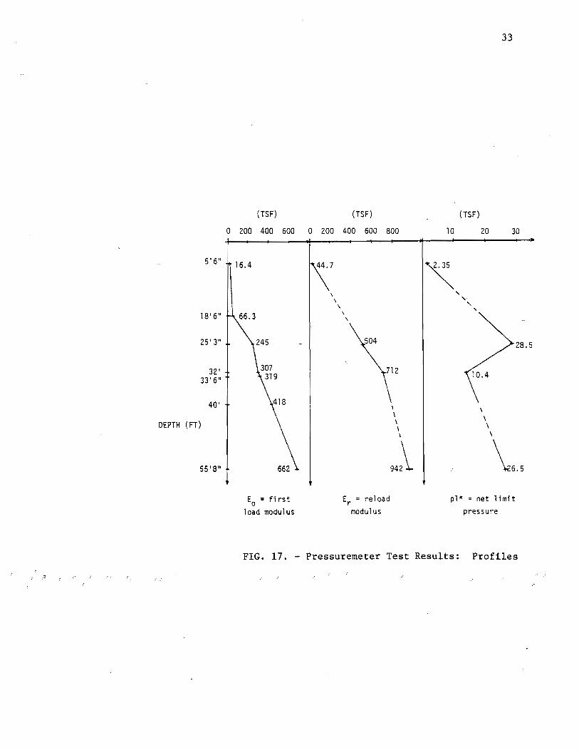
5.1. 3 Pressuremeter Results
The raw data obtained in the field was reduced. Corrections
were applied for membrane resistance and volume losses in order to
obtain the corrected curves.
The corrected p.v. data was then transformed and plotted as a
p, ~R/R curve (Appendix C). The parameter p represents the actual o
32
total pressure against the wall of the borehole, ~R is the increase in
probe radius and R the deflated probe radius. o
The first load modulus E was obtained from the straight part of o
the pressuremeter curve on the first loading, the reload modulus ER
from the unload-reload cycle. The net limit pressure pt* was obtained
by manual extension of the curve. The moduli Eo and ER were computed
assuming a Poisson's ratio of 0.33 in all case. The values of the above
parameters are shown on the profiles on Figure 17.
5.2 Houston Wall: West Belt and Kimberly
5.2.1 Purpose and Scope
A geotechn~cal inv~stigation was undertaken as part of the eva1ua~ .
tion of the foundation conditions for the retaining walls of a highway
underpass. The site is located at the intersection of the West Belt
and Kimberly Lane in Houston, Texas (Fig. 18). Each retaining wall will
be made of a line of drilled piers, 3 feet in diameter with a 42 inches
spacing center to center. At the final stage of construction, those
------------------------------------------------------------------------------------------------------
33
(TSF) . (TSF) (TSF)
0 200 400 600 0 200 400 600 800 10 20 30
5'6" 16.4 \7 ~ \
, \
,. \
, , 18' 6" 66.3 \
\
25'3" 504 28.5
32' 712 33'6"
40' \ \
\
\ DEPTH (FT) \ \ \
\ \
55'8" "l \6.5 Eo = first Er = reload pl* = net 1 imit
load modulus modulus pressure
FIG. 17. - Pressuremeter Test Results: Profiles

34
l
I J
j t
N : - 10-
· .-.. E-4 00 ....:l P<:l >' I:Q ~ E-4 E-4 Ul ....:l P<:l P<:l
J 3 I:Q '-"
~
!
J
-· KIMBERLY STREET
TEXAM PMT ~
~ BORING WB 8-5
FIG. 18. Location of Pres.suremeter Borings .. .. . .
·
..
, .' .. "
,
1 , . .
piers will have a total length of 68 feet and retain 22 feet of soil
(Fig. 19).
The work consisted of performing pressuremeter tests at the site
in order to obtain the soil properties as follows:
first loading modulu~
reload modulus
net limit pressure
A total of seven tests were performed on August 31, 1983. Their
position is shown on Figure 20 along with ~he observed soil layers.
5.2.2 Pressuremeter Testing
The pressuremeter used was a TEXAM model sold by Roctest. Inc.
This is a mOnocell pressuremeter inflated with water. The probe is
70 mm in diameter had has an initial deflated volume of 1380 cm3 .
Seven tests and two calibrations were performed.
All tests were performed in the same boring. The hole was
drilled using rotary drilling with axial injection of prepared mud
with a 4 inches drilling bit down to a level located 3 feet above
testing level. For the last 3 feet, a 2-15/16 inches bit was used
35
with a slower rotation speed and a lower mud pressure. This procedure
gave satisfactory overall results. In the sand layers future drilling
"
might be more successful if a tricone roller bit is used and if the
drilling mud. is thickened significantly.
5.2.3 Pressuremeter Results
The raw data obtained in the field was reduced. Corrections were
applied for membrane resistance and volume losses in order to obtain
the corrected curves.

36
3' PRESENT GROUND SURFACE
ANCHOR T 22'
, j
J
68' .. ,
46'
- -- r 3.5'
DRILLED PIERS ..
. I . , I
".,-'
FIG. 19. Wall Cross Section

, ;
j
~
DEPTH (FT)
T 22'
13.5' 0
23' ~
31' 0
42.5' 0
46' 49' ~
57' •
66' •
37
0'
l CLAY
20.J l SAND
40' J. CALCAROUS NODULES
--, CLAYEY SAND J 44' -J
CLAY
e PRESSUREMETER TESTS
FIG. 20. Depths of Pressure meter Tests

The corrected p.v. data was then transformed and plotted as a
p, 6R/R curve (Appendix B). The parameter p represents the actual o
38
total pressure against the wall of the borehole, ~R is the increase in
probe radius and R the deflated probe radius. o
The first load modulus E was obtained from the ~traight part of o
the pressuremeter curve on the first loading, the reload moduli ERI
and Ei2 from the first and second unload-reload cycles, respectively.
The net limit pressure pQ,* was obtained by manual extension of the
curve. The moduli Eo' ERl and ER2 were computed assuming a Poisson's
ratio of 0.33 in all cases. The values of the above parameters are
shown on the profiles on Figure 21.
5.3 Assumptions and Analysis
In order to analyze the two retaining walls in Houston, the
following assumptions were made:
• Each pier affects a width of soil equal to 3.5 feet.
• The reinforcing steel is such that the cracking moment is
not exceeded in each pier".
• The modulus of elasticity for the concrete is four million psi.
For the analysis using conventional p-y curves, the soil proper-
ties were assumed as follows:
y = 120 pcf,
Displacement needed to develop active pressure is 2 mm.
Displacement needed to develop passive pressure is 10 mm.
For the Menard method, the procedure outlined in Chapter 4 was

13.5'
23'
31'
42.S'
49'
57'
66'
(TSF)
o 200 400 600 800 0
E = FIRST o
LOAD MODULUS
534
(TSF)
1000
358
2000
556
2344
1484
ERl = RELOAD ~!ODULUS
(FIRST CYCLE)
39
(TSF) (TSF)
1000 2000 3000 0 5 10 15 20
1870
1343
ER2 = RELOAD
~ODULUS
3181
(SECOND CYCLE)
20.S
. pi* = :-lET LIXIT
PRESSURE
(ESTIMATED)
FIG. 21. ~ Summary of Pressuremeter Results
used below the excavation level. Above the excavation level, the
conventional p-y curves were used.
Tables 4 and 5 contain a summary of the p and y coordinates used
to analyze the two walls. Z is the depth in feet from the top of the
wall, P is the pressure in psf, and Y is the corresponding lateral
displacement in feet. A, B, C, and D refer to the four points on the
p-y curve shown on Tables 4 and 5.
The results of the analysis are shown on Figures 22 and 23 for
both the pressuremeter and conventional method.
40

41
p
A
----------------~~------------~y
D
P-Y Coordinates from Conventional Method
Z(ft) A B C D
P(psf) Y(ft) P(psf) Y(ft) P(psf) Y(ft) pepsi) Y(ft)
0 0 -1000 - - - - 0 1000
22.5 8064 -.033 1296 0 - - 864 .007
60 20160 -.033 1296 0 -2160 .007 -11088 .033
P-Y Coordinates from Menard Method
A B C D Z
P Y P Y P Y P Y
0 0 -1000 - - - - 0 1000
23 8280 -.0328 1380 - - - 920 .0066
25 22900 -.0337 1350 -.00008 390 .00078 -22100 .0343
32 3720 .. · .... 0136 2510 -.0012'1 20· .. 00408 ... 3120 .0241
56 10460 -.0872 ·4010 -.00691 '850 .01155 - 9860 .10444
60 10460 -.0872 4010 -.00691 850 .01155 - 9860 .10444
TABLE 4: P-y Curve Data for Liberty and Mesa Wall
-~---~---------------------------------------------.
42
p
A
----------------~------------~y
D
p-y Coordinates from Conventional Method
A B C D Z
P Y P Y P Y P Y
0 0 -1000 -, - - - 0 1000
22 7920 -.033 1320 0 - - 880 .007
68 22644 -.033 1320 0 -2796 .007 9999 .033
P-Y Coordinates from Menard Method
A B C D
Z P Y P Y P Y P Y
0 0 -1000 - - - - 0 1000
22 7920 -.033 1320 0 - - 880 .007
31 16640 -.14 1670 -.0016 230 .0056 -9999 .14
42 10000 -.39 2930 -.019 -2100 .04 -7820 .39 -.
57 13800 -.62 4090 -.032 - 940 .06 -9999 .62
68 7280 -.23 4900 -.04 -1354 .06 -5060 .23
TABLE 5: P-y Curve Data for West Belt and Kimberly Wall
,----------------------------------- -
Conventional p-y Curves Depth - - - Menard p-y Curves
(ft) -4 -3 -2 -1 0 1 0 50 100 150 200 .2 .1 0
0 L ____ I- ___ -1_: _ __ .1 ___ • l . ~ ",./ ii' cL- - - .J_, --\ \ \
10 I J \
"\ \ \
II \-l" \ \ \
20 II \ \ "-0:
'" " <-------><:1T II " ---- \ -- . -30 .... I . ....... /
/ ~
/ 40 "" II \ II I
I I
/ 50
II f ') V , ,
I . I I J
60 I I I I, -4 -3 -2 -1 0 1 0 50 100 150 200 .2 .1 0
Pressure (ksf) Moment (k-ft) Deflection (ft)
FIG. 22. Results of Analysis for Liberty and Mesa Wall ~ w

o
10
20
30
40
50
60
-1. 5 -1.0 -0.5 o 0.5 1.0 o - '- - - J - - ,_L - i" )~&W;
(I
-1. 5 -1. 0 . -0. 5 o 0.5 1.0 0
Pressure (ksf)
------------- Conventional p-y Curves
- Menard p-y Curves
50 100 150
I
50 100 150
Moment (k-ft)
0.2 0.1 o _,_..1 ___ _ \ • n1Vh>
0.2
\ \ \ \ \ \ \ \
0.1
I
I , , , I , I I
I 0
Deflection (ft)
FIG. 23. Results of Analysis for Kimberly and West Belt Wall
+--+--
45
CHAPTER 6: CONCLUSIONS
The results of the parametric analysis show that, for the cases
studied, the influence of various parameters on the top deflection of
the wall is as follows:
1. When the slope of the p-y curve is multiplied by 3. the top
deflection of the wall is multiplied by 0.65 and the maximum
bending moment is practically unchanged.
2. When the angle of internal frictio~ of the soil is multiplied
by 1. 40 the top deflection of the wall is multiplied by 0.35
and the maximum bending moment is multiplied by 0.5.
3. When the drilled shaft diameter is multiplied by 2, the top
deflection of the wall is multiplied by 0.2 and the maximum
bending moment is practically unchanged.
4. Maximum benefit is obtained for an embedment depth equal to
1.4 times the cantilever height (height of retained soil).
The analysis of the two walls in Houston was made using a
conventional analysis and the Menard pressuremeter method. The results
of the predictions show that, in these two cases:
1. The Menard pressuremeter method predicted 25% and 50% less
top deflection of the walls than the conventional method.
2. The Menard pressuremeter method predicted maximum bending
moments which were 15% and 39% less than the maximum
bending moment predicted by the conventional method·.
The above results need to be further investigated at full scale
in the field at the time of construction and also at small scale in
the laboratory.

CHAPTER 7. REFERENCES
1. Menard, L., Bourdon, G., and Hcuy, A., "Etude experimentale de l'encastrement d'un rideau en fonction des caracteristiques pressiometriques du sol de fondation," Sols-Soils No.9, pp. 11-27, 1964.
2. Menard, L., and Bourdon,G., "Calcul des rideaux de soutenement: methode nouvelle prenant en compte les conditions reeles d'encastrement," Sols-Soils No. 12, pp. 18-32, 1965.
3. Menard, L.,Bourdon, G., and Gambin, M., "Methode generale de calcul d'un rideau ou d'un pieu sollicite horizontalement en fonction des resultats pressiometriques," Sols-Soils No. 22-23, pp. 16-29, 1969.
46

- --- --------------------~-----------------.
47
APPENDIX A
RESULTS OF PARAMETRIC STUDY

o
10
20
30
40
50
60
Influence of the Slope of the p-y Curve on the Wall Response
-- ~lope = 50 psi/in.
-300 -200 -100 o 1..-- -- __ L __ ·----L------
-300 -200 -100 0
Pressure (psf)
------ Slope = 100 psi/in. - - - - - - Slope = 200 psi/in.
100 o 500 1000 1500· 2000 3 2 1 0
100 200 o
"",/ ./
/"'"
~;' "'" " "..
to "." "'" / "",/
,/ '/
500 1000 1500
Moment (in.)
.\ I J
I ,/
2000
--~\~ t--~---\ \
\ ~ \ \
\ ~ \ \
\ ~
3 2 1
Deflection (in.)
o
~ 00

Influence of Angle of Internal Friction on Wall Response
- - - <j> = 25 0 <j> = 300
- - - <j> 35 0
Depth (ft) -200 -10'0 0 100 200 0 500 1000 4 3 2 1 0
0 ____ .L. __ -'----.t //A/I
t i I .rN "', J - - _ J - \ _\ _ -L ___
" , " \ " \ 10 II '~. I 1'\ ,
\. , , '\
\. , , 20 II -.~'); II "~
, , " , " ....... ~
\ \
\
~' ~~-"/II II "~ \
30 ' ..... \
\ .......... \ .... \
I " ..- " ,.. ..... / \ \ t
, 40 .... /' J
" ..... , ./
" ........ ", ./ --~ "
/' ./ ..,. " --/
,,-.... -.- -50 I r - -~""-- 11/ ---- -~ .... ,....-.... ....
" " .... 60 I r I I
-300 -200 -100 0 100 200 0 500 1000 1500 2000 2500 1 0
Pressure (psf) Moment (k-in.) Deflection (in.)
+:-~

Influence of Pier Diameter on the Wall Response
-- - -- Dia; =2 ft ----- Dia. = 3 ft - Dia. = 4 ft
-300 -200 -100 o 100 o - L - - - - - -'- - - ~ - - ... - - - -, I 'lAUD
10
20
30 ..---
<-----40
50
60, 4, >
Pressure (psf)
o
/" /
500 1000 1500 2000 6 5 4 3 2 1 o ~_.l __ .J __ ';"_ - ~ -'C--- I , bxm
... / /'
,...,'" ... /,'"
Moment (k-in.)
, \ ~, \
"-, \ ", \ " \ ,
" \ , \ "......-",..~
'\ , \
Deflection (in.)
I.Jl o

Influence of Embedment Depth on Wall Response
-- - -- Depth = 48' ----- Depth = 60'
-300 -200 -100 0 100 o L. - - - - ..L - _ ~ _.L - - _ .... +---mrr.r-'---i }JAh}
10
20
30
40
50
60
( ... -
", ... .... ........ .....
~ ---
70 TI----~I~·~--~·+I----~n~I~----+I~:~I----~ -300 -200 -100 0 100 400 500
Pr~ssure (psf)
o 500 1000 1500 2000
o 500 1000 1500 2000 Moment (k-in.)
3
~-\
\ \
\
- Depth = 70.5'
2 1 o - J - - - -,- -- »Jtuli
\ \
\ \
\
3 2 1 0 Deflection (in.)
V1 ~

Depth (ft)
o
10
20
30
40
50
60
Influence of Variable EI on Wall Response
- - - - Middle Third of Wall has EI Reduced by 75% -----------Normal EI
-200 -100 o 100
- - - ..J - - - - .'J - - - JJlX)})
-200 -100
Pressure (ps£)
o 100
o
o
500 1000 1500 2000
500 1000 1500 2000
Moment (k-in.)
4
\ \
\ \
\
3
\ \
\ \
2
\ \
\
1 o
3 2 l, 0
Deflection (in.) Vl N
53
APPENDIX B
SOIL DATA: KIMBERLY AND WEST BELT

54 .;.'
!"'"
7 .-, i
] tr
~ TEST 1 t - I SITE I HOUSTON i
':.- I ! 6
1 WEST BELT I KIMBERLY '" ! t ~
~-, ! DEPTH 13. 5' I ! ,.. CORRECTED DATA j
:.., I i i :
5 I -1 t-
.:..-. ! I i ; l- i I i !
4 I
r -t I
i . !
1 f
r-I I
j) Ct..f') j 3 i- l I
I I i I ,
!
I i
! J I
2 t t-, I I / i I r i I I !
1 I ! ..... ..,
-!
l ~ I I
" ~
~ a 10 20 30 , 0,
;,;.:." (0. 1 t.o R)/Ro ex) "'-
E = 144 TSF 0
r~· pl* = 6.5 TSF (ESTIMATED)
~
rr [ L
r-0 ~ '--
. l I
6 L. , I i
r . ! ,
5 :-I
! : . ,
4 li
I l-I
i j
P (t..f') 3 ~
I I
i I !
2 r
~
I I
1 I ~ !
TEST 2 SITE I HOUSTON WEST BELT I KIMBERLY DEPTH 23' CORRECTED DATA
I
I i
i ,
-! ; I
i i ~
11 I I
l . ~ J
, 1
i 1 ; I , 1
-: I
-of 1 I i
oi
ll o __ ~ __ ~ ____ ~-L ______ ~ ____ .~I ______ ~ ____ ~_
10
<D. 1 t.o R) IRo ex)
E = 47.7 TSF o
ER = 358 TSF
pl* = 6 TSF (ESTIMATED)
20
55.

.~.
r-
t.":
~
L.: ..
'"
p. ;
I I..
~:.
: , ..
c
~ , ;:
I r'" , :
<..
~'("--
t-b..._
,... ! • ..
P (t..f)
18 I
~ i
16 r i
i to J
I I
14 ;-
r J
12 !-
.. I
1((J i t-
~ J
8 i t-I I I !..
6 l-I
I - L , j
4 r-I j , li I
:1. o
- ----_._-----------------,
TEST 3 SITE I HOUSTON WEST BELT I KIMBERLY DEPTH 31' CORRECTED DATA
" ..
10
(0.1 t.o R) IRo eX)
E = 179 TSF o
ER1 = 1541 TSF
ER2 = 3181 TSF
p1* = 20 TSF (ESTIMATED)
~--~
I J I
I( I
I
I 111 r I .. !l~
if I I: ! ~ -4 fi l ~ !
I~ t I i ~ : I i I
jJ I : • I
i
i I I
1-4 I ;
1 j 1
i -i . I ... !
--! i
-l I
I ~ ___ -,--._. ----I.
221 321
56

57
18 J
1 ~ TEST·4 1 SITE. HOUSTON J 16 ;.... ,
~ I WEST BELT I KIMBERLY I !
r DEPTH 42.5' I
L 14 CORRECTED DATA I --'
! I ! , I
r 1 I 12 - ,-i !
I ' I i
I ti , r I
10 t-1/ I !,-t ~, I I.
I H I
L p , I U 1 \ i ~ I
P Ct..f) 8 ~ - rl !
t ; ~ , ~
! i i i ,/
11 6 !- I
[:
I ~ , r . ~ I
I I i
I I
4 I I
r .... i I I
l-I
I
1 i
! \ I
2 , r -,
I
I ,
I
,--~ I 0 --- I
0 10 20 ~0 ..
. .
co. 1 t.aR) IRo CX)
E = 235 TSF 0
ER1 = 1188 TSF
ER2 = 1870 TSF
p1* = 14 TSF (ESTIMATED)
~

r< ..
" ! .
I,'
~ r·" f·· il: ...
r" ~: t ..
~ ~,
r; t.
P (t..4=')
18
16
14
12
10
8
6
4
2
0
I ! I l-
i I-, I \ I
I-! i r-I ! L
I l-I I I I-
I i i , ! ,
i ~ , I I .. I
I ,
i-I
; : .. i ! r
l I ! I r-I
I r 0
58
-r---Il 11 TEST 5
SITE. HOUSTON -;
I WEST BELT / KIMBERLY ~ DEPTH 49' I
CORRECTED DATA I -I , , i
..I
J I ! i
1 i I
/ ! ,
f I
-l
I I I I
l i I I I I 1 I I i
-4 I
* ,
! ..j
I i , i ~
i I
-1 I i I
_I •• I
10 20 30
'(0.'1 t.o R)/Ro eX)
'E = 770 TSF 0
ER1 = 1556 TSF
ER2 = 1343 TSF
p1* = 14 TSF (ESTIMATED)
59
,~.
.:
18 I -r i
'I I I
1 r TEST 6 I I
~ I
;- SITE I HOUSTON ,
16 ,
I I I WEST BELT I KIMBERLY I
to DEPTH 57' 1 J !
i
I I CORRECTED DATA
, 14 I- -4
I I, i i I 1- ~ .,j
,
J I
i I
12 j..... -' I
( ! !
I I
1 , .. -t
: I
I I
I
I j
10 +- ....; i I i I i
, .. ., I I
I i .
(t.ef') i
p 8 t- ~ ! I
! I
I I
i" I ., ,
6 , ....i r I
i I ! , f j
, l- i -, f ,
i " 4 r- ...J
.. ., I I
I 2 ..., r I
I i , I 1
0 ___ ----l..
0 10 20 30
co. 1 t.e R) fRo . eX) .
E = 367 TSF 0
ER = 2344 TSF
pl* = 20.5 TSF (ESTIMATED)
.....
r \~. r;.;. •.
II!:'" r: !: ~
'.
,.... r k I • ....
", !. , 1'" k
r ~,:
' ..
r .. ~ ,": fu. ..
r r; It..
.. E
7 I l-
I I
6 L I
! ! I !
i I
i
5 ~ I i I I I r i
4 ri
po
I p (t..f) 3 ~
:-. I
2 r !
i 1 r-i j
I 1 r
!
TEST 7 SITE • HOUSTON WEST BELT I KIMBERLY DEPTH 66' CORRECTED DATA
I I 1 i :
~ , I
i I I
I
l I
1 1
~ .
r 1-0-__ --'---.--1-.--..... ----1-1 .• ____ ..,l.. ___ ..al
1m CD. 1 1:.0 R) IRo" CX)
E = 534 TSF o
ER = 1484 TSF
p1* = 14 TSF (ESTIMATED)
2m 3m
60
. IIIUI.I,I:~I. IHJ'II!P
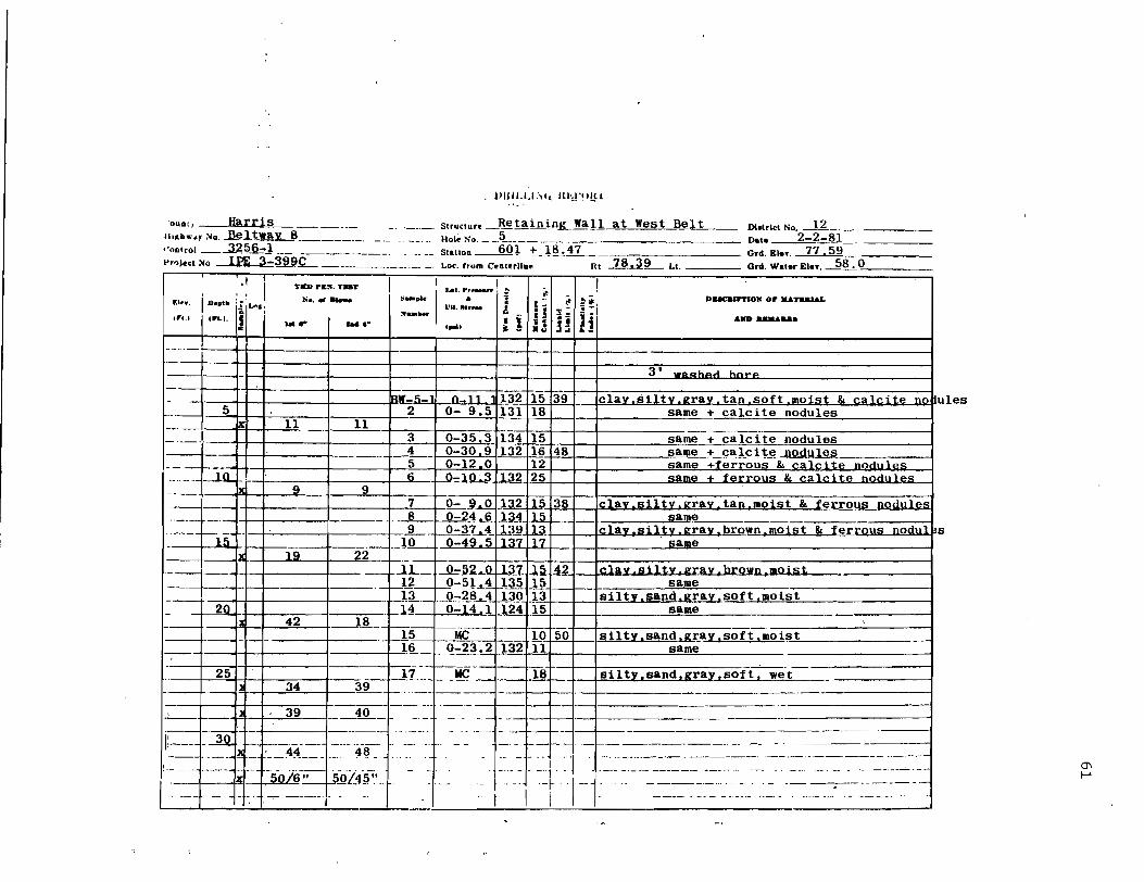
'OUOt, Harrj.s IIoKb,,'.)'loIo . ..D.~.ltway 8 __ -"- .. - .-. ---. Structur. _~taininJL Wall at West Bell "nolrol _....3.~~.2=-1 ---.-. - - .. --.. HoI. No. __ .5_. ___ . __ ._
Dlolrlel No, J£_._ Dal. 2-2-81 -----
l'r'lJ.Cllolo ~ 3:W.C---·----· SlalloD--.&.Ql + 18.47 - ----------_._--Grd. £In. 7'1-:59-O.d. Waler Eln. 58.15 Loc. from CeDtf'rJiae Ht 78,3~ Ll.
.F.I ....
.1 I , . 10
.....
1 :-il""":
In... S ..
Till> pal<. TaT
~ ........ . "I.t ..... . ....
I I
~-p"1 ~."~I'
IAI ... ,._/, !I . .. . VI •. H..... !
..... , : 1 i! _I -t: "~"' . UH HI
DUClllrrlOll or IIL&nauL
.IID .......
I I I. I-+-+-t-I -+-------------,------1 3 -. waClhAA hn .....
'-" :;~ ~9 l_~i~i ~=lT8t 3. Isilty.sand.g~~y.sOft. we't
4" I' U~ 1. __ 1!L_.:~--=~--t .. -- 1·--\-------- - --1-- -I 1--1----·-J-301i-£ ~ -----I~= ~ ~&~' ._~4~~~=~ .. =--- ~-~~ .. --. -
!!.---'1'--.-.,~:l.--t-~-~ :;'-,...-] 50/' 4fF' _ ~~jL---+-, __ ._ .....
--- ..... ~-. 1 1 --\ ---.-.-- ._--1
~~f11-.r:-:~~--~-=~-_=:·~-:~~~.~. _~ _.-:-.- ~~ -;. -'1-1 . I ,.. ---- --- --- .. -.'-- ..... -..... -.----- ...
(J\
I--'
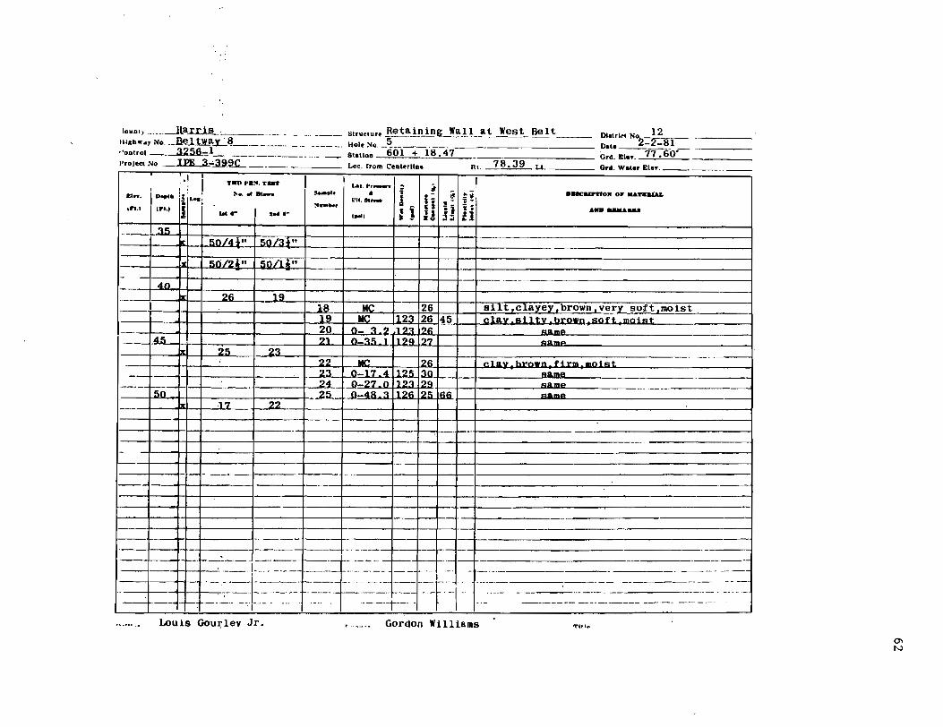
lOUD'; ---1laxtl!;L _____ . _____ . ___ . Structuro Bet~ln)Eg._Wal) at West Belt IIIKb ... y No. __ ~..lbt..aL~ ______ .. _._ Holo ="10. _~ __ ._._. __ ... _____________ _
,'ootrol __ .......32~.6.:~1 _____ . __ . ___ . Statloo 601 + 18.47 ___ '.--:::-::---
DI,lrl.t No 12 Date ~-2-8iGrd. Kin. '1'1:60'Ord. Water EI .... I'rojeet="lo ,FE 3-~.9c...._____ Lo •. rrom C'eotorlloft Rt. 2 8 .39 Lt.
, 1 ;'; I i D ... k
l i!ilA>c;
IFl.' J £1 •••
,re.'
~~
4n
T.., Plt!'f. TJaIIT
~ ......... we- .... -
~n/dnl 50/31"
50/21.n I 50/11.-"
21> '-19
~··-I' . ~I ~pl4' • "i IVIt...... a II ! !'If........ 1 i II • , ... , . - • ;J
Duc:urrIOM OF ..... TIlaLu.
... ND .........
18 Me 1261 sUt,clayey,brown,very soft,moist 19 I Me -Ti23126145]~eia--v---::::SUtr_brown :-80f1- mnid
~=+r--+~-+----=tl ::z2°ijltJb°:";a:s:u3:2 'r~ ~~ ]~~ I I I :::: =1 -~I~ . 21 _ 0-35_1 ____ . 1~'-~ 23 25
22 1jf(;-~'-1261 c1&Jl.brown.f1rm-=-,,;oiFlt:
--15n=1=11 ., ~:-4~:!lt~~m~6~+t-+I--.tIAl:!:IIlI:L:-----Ix -.i7 22
--+-~-H-I- I I------------------J -4 II I. 1 I
I I I I·----tl----------------·
.---4-:- I .--1-+--'-----------------------
1--1 II 1'3---'~=F" -f=~·~-~-tfr .. · j~j".--.- .. =l +l--+-=-~--== --=. --~~··--:---~f'-··~~I··:···j··-:~:-· ---. -.-----~+-+-"-'---I---' -.... -... ' ··----t--··· .--.
-- ._----------- - ._--_._-- - -~. _.-
Louis Gou~lev Jr. Gordon Williams trUt"
()'I
N
~5 2111
El .... cI h
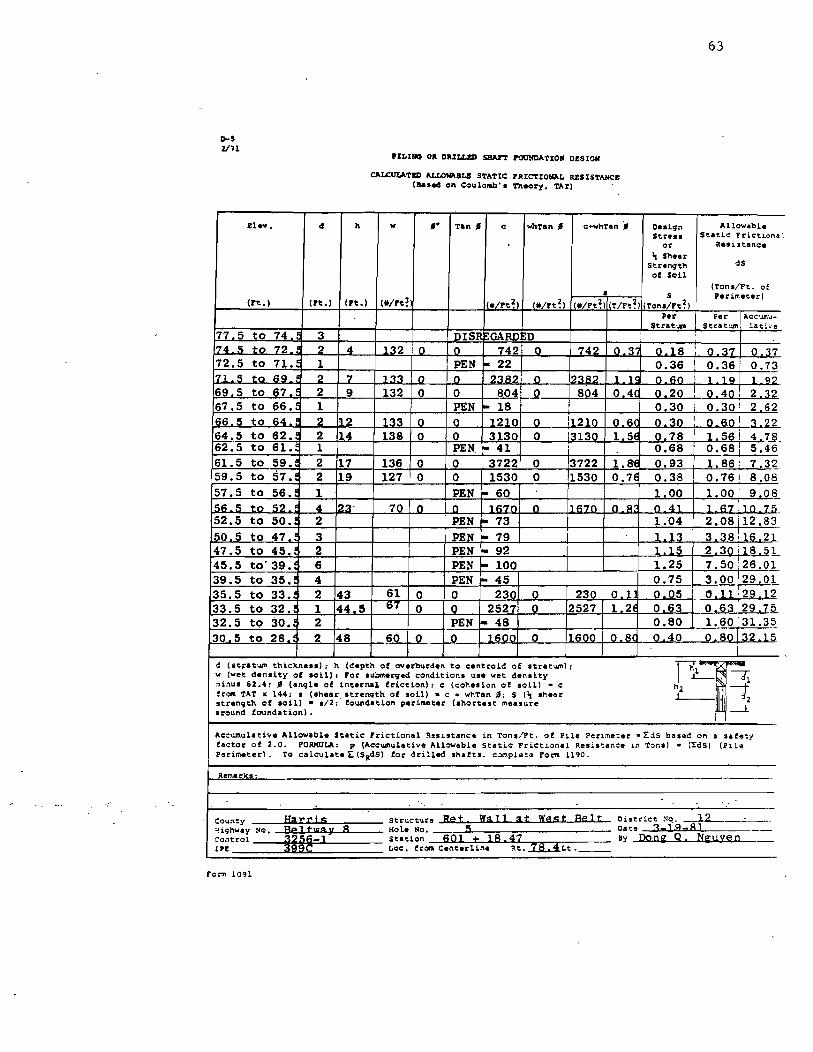
PILIIIG 011 DlUI.I.!:D SHAn rOUNDATION DESIGN
CALCULATED ALLO~BL& STATIC rRICTIO~L RESISTANCE (Ba .. d on Coulono!>'. Theory. TAT)
" ,. Tan' e whTan , c+whTan -.
•
63
Dedgn Allowable Stres. Static Frictiona:
or aesi.stanee 'I She ...
Strength dS
of Soil (Ton./Ft. of
S (rt.) (Ft.) (rt.) (*/rt~ */Ft~) .1*/rt~) */Ft~) T/Ft~) (Ton./Ft~)
Perimeter)
Per Per Acc\llll.u-Strat'"" Strat·.l/II lative
77 5 to 74.1 3 DISll ~GARD ~D I ,
74 5 to 72 ~ 2 4 132 0 0 742 0 742 ~ 3~ 018 0,37 0.~7
72.5 to 71.~ 1 PEN ~ 22 0.36 1 0.36i 0.73 171 ,5 to 69, f 2 7 133 0 .0 2382, .Jl 12382 ...l,lj 0.60 1 .1 q 1 Cl2
69 5 to 67·!' 2 9 132 0 0 804 t-..2 804 o 4( o 20 I Q.40, 2.32 67.5 to 66.! 1 PEN I- 18 0 30 : 0 30 1 2 62 66,5 to 64 ! 2 112 133 0. _0 1210 0 112.-1.0. Jl 6( 0,30 I O.RO! 3-.2.£. 64.5 to 62.1 2 14 138 0 0 3130 0 13130 1.5E 0 78 1 56 i 4.7~_ 62.5 to 61. 1 PEN. roo 41 0.68 i 0.68 ~ 5.46 61.5 to 59. 2 17 136 0 0 3722 0 3722 1.8E 0.93 1.86' 7 32 59.5 to 57. 2 19 127 0 0 1530 0 1530 0.7E 0.38 1 0.761 8.08 57.5 to 56.: 1 PEN ~ 60 1 00 1.00 ' 9.08
15R.5 to 52.: 4 123' 70 0 0 167.0 .Jl 1l.67.o. .Jl..B. n 41 1.67il0.75 52.5 to 50.: 2 PEN l- 73 1.04 2.08/12'.83
50 5 to 47.: 3 PEN ~ 79 1 1 n 33sT 16 21 47.5 to 45.: 2 PEN i"" 92 1 15 2 30:1~L 45.5 to'39. 6 PEN I- 100 1.25 7.50'26.01 39.5 to 35. 4 PEN 1"- 45 0.75 3.00'29.01 35.5 to 33. 2 43 61 0 0 230 0 230 0 1 0 05 I O,11! 29 .12 33.5 to 32. 1 44.5 IH 0 0 2527 0 2527 1 24 0 63 o 63~~ 32.5 to 30. 2 PEN J- 48 0.80 1.6031.35 30 5 to 28.: 2 48 .!i0 0. _D 1600 0 1600 0.8( o 40 0.80132,IS
d (.t~atum thickne •• ), h (depth of overburden to centroid of stratum),
p~ w (wet density of .oil) , For .ubmerged condition. u.e wet den.ity ~inu. 6Z.4, , (angle of internal friction)r c (cohesion of soil) • c
h Z ' --t from TAT x 144, • ('hear .• trenqth of loil) • c + whTan " S ('I shear .1..--..1 :iZ strength of loil) • liZ, foundation perimeter (.hortest measure
i 1--1 around foundation), I
ACCUJl\ulaeive Allowable Static Frictional R.sut.nc. in Tons/Ft. of Pile Penmeeer zL.:IS bosed on a sate:y factor of Z.O, FOIlHULA, P (Accumulative Allowable Static Frictional Resi.eance In Tons) • (I:dS) (Pl.l~ Perimeter) . 1'0 calculate I: (SRdS) for drilled shates. comple:e> Form 1190.
aer.larks·
-Coun'ty Hal:l:is Struct>Jce Ret l{all at l{est Belt District :<". -.-.lL-__ . __ ~i9h"".y NO. Be1tllla:\l 8 Kole 110. 5 Date 3-1·9-8] Control 3256-1 Station 6Q1 ± lS.~:Z 8y DoCi Q. NilJ.:/:§11l IPE 399C LOc, frOM Centerline Rt. 7S.4t.t.
fe,,", 1091
D-S 2171
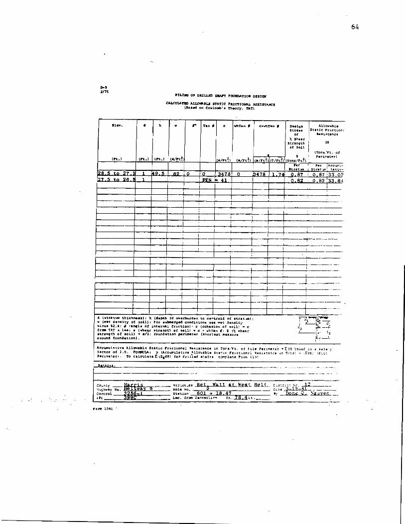
Ill." • Ii
PlL%1IC; OR DIULLBD SRIIrr PClIJIIDATIOIC DI:SIQII
CA.t.C1:1IATIID AUOMIau STAT:C PIUCTI~ RESISTANCE (a •• ed on Coulo.,". Theory. TA't)
,- Tan' c ""'Tan' c:.whTan "'
• '''/Ft~ ('!IFt~) "L!t~) (T/Ft~)
n •• lqn ~llow.bl.
Stre •• Static Frl.eti.o~: or R.'.tltanCt
'r Sh.ar Strenqth as of SoU
(Tons/Ft:. o! 5 i Perif"'!eter)
(Ton./Ft~) . Per
Itrat..n
128 .5 to 27. ~ 1 49.5 62 0 o 347B. 0 114'Ut 1 74' ~ 87 o 87 '33 02 1 I PEN 41 I o 82 o 82 '33 84
~------~-4--~--+--4--~--+i'--~--~--+-~~~--
~----------r----+----+----+---------+----~-----~---+---+-------------------
~--------r---+---~--~--~---l---4-----+---~--~I----~ __ -------~----~-----l-_-+--"---_____ +-J_-,, __ -..,~ ___ :-_-+-_--L.. ______ _
~------+-----+----+-----+----~---~----~~---1--~----+-----t------------
------'----t----t------~--------..
1 ! !
I
d (Itutum thielen •• a): !\ (depth :Jf overburden to cerot.roid of Itrat"..un): w (vet denli.':Y ot .1011): For aYlxMrged conditi.o" .. u.e vet ~.n.ity !IIinloll 62.4 ~ , I.ng1. of internal friction) ~ e (colt •• ion o~ .oil~ - e fr~ TA":' x 144: I (!th •• r tttr.nQt~ of loil) • e ... h':'an ,: S (" _hea: a~r.nc;th of aoil) • • /2: fOUo"\chtJ.on periJfteter tat,orteet rr. ••• ure around fQund.t~on).
I
I
J I
Gl""'1t~ I ~~. ":
'2 ~ --~ _I ___ ~:... .:fz
L __ l ! .
ACCUIDul~'!.iv. Allowabl" Static Fr~e:1on.l R •• ia:ance 1n Tora/Ft. of i 1.1e Perl.me:e~ • r ~S =~sec =:"1 a sa ~~:y factor of 2.0. F'ORMUUo.: p (Aceumulatl.ve ."llo.able SC4tlC Fne':l.onl'l ?e5l.s':!:":.:e l.~ '!:-r.3: ;; ,!":s: tr-..i·:; fen,me!.erl. 'to C.l~.11.~.l: tSil~S) for dril-le4 _~.!t. ~'::>l"l.r-lQ,:e FOrT!: !.l~:.
--_._----_.-----------------------f--------------------------------------.------------
64

65
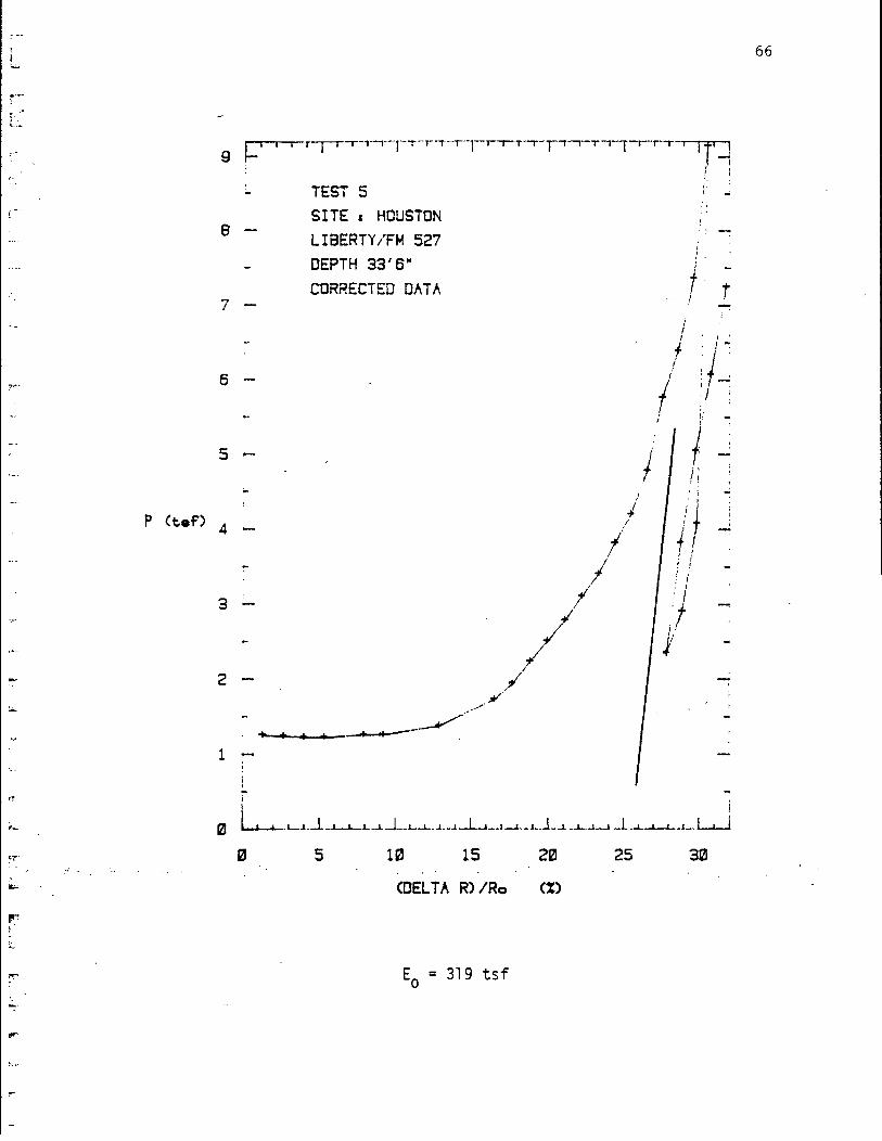
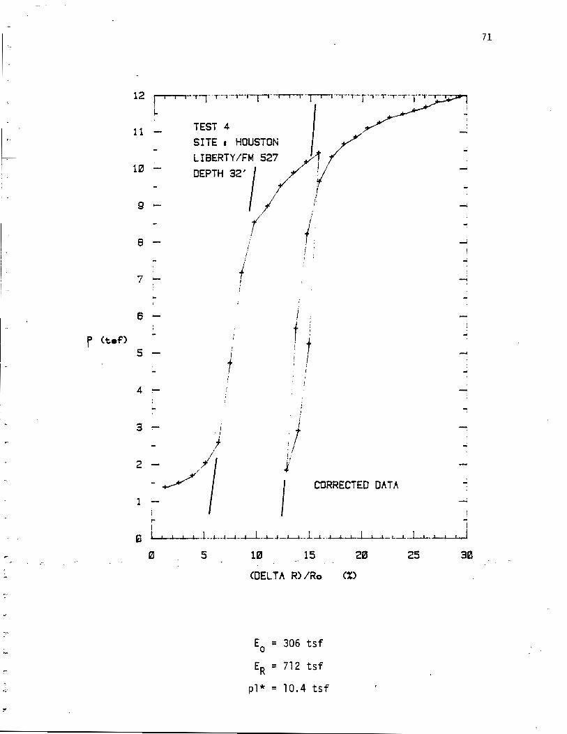
APPENDIX C
SOIL DATA: LIBERTY AND MESA
, . ~.-
r---
....
~.
~.
"-
,;"t"
:0:.
il;..:
r.r ~ -~
,..,.
0- .
.... ~. ~.
I I 9 r-
8
7 -"
6
5 ....
P (t..f') 4
3
2
TEST 5
SITE I HOUSTON LIBERTY /Hi 527
DEPTH 33 / 6"
CORRECTED DATA
~4-4-__ --""~""----~" + ... ...... -'
1
i
/,'
/./ .J/II'
/
I
j /
./ ;/
I
If'~ r j-
, .
1 :
l-f r
/ I I'
f :!-: ; 'I' ! :, ~ ; /-
, ;
! i ; i . I
.f }
-
i i
0 ~.L....1_-L_.L.....L.-.l- • ..1. .J. __ J-..J.._ .1_.1-l--1 __ 1~ _l-.l_..!. _-.1-.-1--1 .J. -l-...L-L-_l __ L......J
5 10 15 221 25 30
<DEL TAR) IRo (X)
Eo = 319 tsf
66

15
10
-P (t..f)
5
,·--..--rr-,.--,-..--ri--r-r-'-""---r-j -t':
TEST 6 SITE I HOUSTON LIBERTY/FM 527 DEPTH 40' CORRECTED DATA
5 10 15
(DEL Tit R) IRo
Eo = 418 tsf
20
c:)
i I ! i
I i I ,
25
I f ;
i
I I
} ~ I ;
i ~
I I
~ . ;
-,
! ~
30
67

, ,.
I'
2
1.5
P (t..f)
1
.5
!"'"'"-r'--r-r"-'-'" -r-1-·--r-T-'-T-·-"--'-1 ,
TEST 1 SITE c HOUSTON LIBERTY/FM 527 DEPTH 5'6"
CORRECTED DATA
I
t/ !~' /';,
Ii ! I
I ;
l ;
,/ I
// l'
i! .'f '/
;/
1
I
t/
/ f
..I
-
, .. f \ i
2! ~4_-1.. .. _~-L- . .l-.L-.l-_.1,.J...l._.1-l-L..-, __ L-'---.l--,-~.I- I I I
5 113 .15 : : 213
(DEL TAR) IRo eX)
Eo =16.4 tsf
ER = 44.7 tsf
p1* = 2.35 tsf
25
68

P (t..f)
! I I I I I -r-'-rT-" T-'-r'-'-I-T-r-r--r-rTll--r-'''--rT I I I 6 - ~
5 :-
4 -
3 -
TEST 2 SITE I HOUSTON LIBERTY/FM 527 DEPTH 18'6"
CORRECTED DATA
5 10 15 20
(DEL TAR) iRo eX)
Eo = 55.3 tsf
; I
I I
/ ..
! I
25
r J / I
30 _35
69

!. ~-.
c .. , .. . ; . ' ..
L
f:-
IV: .. ·
\ I
\ , I..
f ;
pr ~ .-L·
22 --
213
18 -
16
14
12
P (t.af')
113
8
~
6
SITE I HOUSTON LIBERTY/FM 527 DEPTH 25'3" CORRECTED DATA
i
l i
I l
I
l
5
/ ./ I
113
,. I ;.
r ! ,
15
<DEL TAR) IRo
Eo = 245 tsf
ER = 504 tsf
pl* = 28.5 tsf
213 25
-I
30
70
r (t..f)
12 , i
L
11
10
9
8
7 ;-
6
5 , -
4
3
2
1
i--"'I'·-T-l--r--r-'--~-1"--r-T"-r-'-T.---r-T-T-'
TEST 4 I SITE I HOUSTON / LIBERTY/FM 527 ~i;t
DEPTH 32' I / Y I f
( l i .1 j
i
I ,
t I
i ... I t
f ! ! , t
~
i
;/ : " J
1 CORRECTED DATA
!" I I
a I I .L_L. __ J-J_-J.-.i._...l--I_.L-.J_._l--,-_.-'-'---l-~-I.-'--~ I I I j
0. 5 1121 15 2121
<DEL TAR) IRo (%)
Eo = 306 tsf
ER = 712 tsf
p1* = 10.4 tsf
25 3121
71

r-i I
i:.
Jr-
, l-I I
25 ~ C
i:
,..
-20 -
~
r-
15 .....
P (t.af)
10
r I
5 l-
'--
r-'
Ir-' ,-
'"-
~ .-~. '
~
,.,"
TEST 7 SITE I HOUSTON LIBERTY/FM 527 DEPTH 55'8" CORRECTED DATA
5 HI _ IS
! ..f
;
-l
-i
, ... I ,
..; i .. i , .. I
I , ...
~ , I
4 I-l.-...I.-L _.1..-L-.l-~_ ~.-lIL.--J..--L....J1
25
(DELTA R)/Ro C%)
Eo = 662 tsf
ER = 942 tsf
pl* = 26.5 tsf
72
'",
r ..... nl ••• .,.beP'U', ... t
".'''''M DRILLING REPORT (For UI. with Uadl.ta.bed Bo .. pllal & To.tlnl'
CouDtT .... Harris .. ~ ___ Btr •• t.r. Railroad Underpafls DI.trld '110 ...... 12"'. 'c" ",-__ "'"'"=-__ ---
lII«hwa:; No. FI:f !>~7 n"l. tl~. 4 Oato -U-79 CUDIo'ol 900-1._ .. __ .. ______ ._. ___ StaUoa 423 + 08 _____ ord .• loT. __ ·_'1:;:6~.~0:..-____ _ Pro!e.t No. II,];: 3-;:\'39 1.0 •• trom Contornao Rt. • ·Lt .. 53 O.d. wat~r IDIOT. r' II I·
YBUP.N.Ta ... ' i ...
rJ... I D •• I. lillA"' II ..............
~"'.f ,n.) I) Jet.'" I t .... "
II_pie • . - '#. b'#-\ \,.,.r._n/ r'l ~I -Il Hom'" ~:~:... ~ j IJ Ii Ii
Daec •• pytOIl 0" ~n~
• "D",,, __ .+.., It, '!< •.
tj:=--=--=-==I~-t=l---'~'='::~~-'-:"]: 'IE---.fil1n ta.lle. ~_.~ •. flli.. '. ". .::;;~~~~.'-".-'. '.~ I .-1------11;-, - .. - "-' - -._- .-, - -......:~--. '. . . , .... _,_.. . .
, . -'- • '"" . ....;J5,-' __ _ . __ .... ---.- --1---1----
:~II~~;~ ~=:~ _~-l=~~~~=-~-tl;;==-==== \
q 12" 32'" 2 ,,'- h • .'. / • . ' " .. ~ __ ~_._~ .. _.~_ ...... __ ~ .. __ . .:: _____ ·. __ .n _ .. L _ . ___ w.......cly,.-l.Irm1D..,..._~J..r..t:.,.-molst wca1csreol.
I 10 () "2 l?fl 23 . "'M' ll"h+ _" . • 4 -. .. . .. . " '~' ." ........ _. _._ .. ___ J .•. ... __ .• _ ., __ ~,.Ji~~t; lylwn, gra¥" stfff D'Ofet~
30'::.~)!i.' ' •.. ~}L·~ ~_, ... '=-~=-39.. ~_ ~~58. = ~~.~ ,". .1
.l._---'_-l-Clay •. sli"bt sand, sl H. dark grav, soft. ,,!Oht _~am~".~ ________________ ~~_
.. GlaY.,.JUWdy..,. gray, tail, Gaft) mof ~t
·1A~_-+---I.sBme . ---..... ~----l ._._- ---- .s,li.li.ihUba' -I(,.fSlCC:.).)~I'--_______ ---:""""_""""_---=~_-:----'5- -". - .. 5-- .
-,,--,,- --,,- I n~~~...l.t........gmy, tan, "ort, wet
£5__ ti.n~.lt.~ • .....tan ___ 8Qft, WIlt,e)' bear!ng
.::-=~--' ==:==~o·-- -------=-.-.:: ~-= ;Q.: ::: !If: Bboye . .-;. ____ . __ ..,..........,.-.,.-_-1 ]2'-- 15--- ... - - !J.1!i~ileLl1.e1l. . -.: .::-~==~= =~~ ______ " _ "" _ .~Iill.<l,.J1Q~ . ...ou.L-;:-:
. Same
_~;i:-j"L :~~_~~~ ~=;_ ~ :~j~~-=~:--:=- ~-==
-5-
.---f±o-
;),.5·-
:!3 2'j
. ____ . ___ R __ ... .!Q....--!lQ.. ..:. Z'! Clay:,._hrawn, .. Jl.tif:4..mo.ist,,,w~S-- .
I ·~- ~-=-·-I'- :-:~--'I r4~"~", ~~.- B~ ~~.' ~%: 'CJ~' ='_ .-.C_~(~e.~~~~li~:-~~~~~~:t~r be~1'1~ I ' I ___ l.:!._--L9 ___ ._1'll3'i 19 54 __ Clay, Sl..Lty, ul'own, 8.1u, , .. Ol~"
3) I~nh ::"I'illf~f·t· ILK. CUJ'SOll I'rlllf!r .. _.. .. _ 1.lIg~.·t .. ~ .. __ .. __ .. __ .. __ .. _. _____ ... _____ .... ___ ._ ._ 'rll'f'I~. __ ._~ ____ , __ . _____ --'. p".\1,""" "'" ... , .... , .. , .. " .... 1 .. 1': ,.,. e ...... r .. rn.· ... )·. '''.''1 .. .- 101.,,101 'tI .. "" ,.tI~ , ... · .. v .. ,)', ., .... rIO.""''''' IX' fur u"'tI.hnl> •• II."u .... ' .. r' .. n."It<. ,_" .. ". ~~~ _ IIW,"9111!IbF·U:ulI:I·'l'ItM -...J
W

T.aao HI ...... 1)."'''&1 ••• ' ....... H D1t1LUNG REPORT
(Fo. u •• with ·UIld.\.tarbo. 8.",,110& '., T •• Unl)
Hi" '. 12 Couot, arr B •. Bt.uetar. DI.trlo~N~'4"';;;;;~-'-=-____ _ lII~b"."NO:~ __ . ___ . llol~No._~ 'Dato '-J. -'(:,1
Cootr,,1 . . lltatlon 423 + 00 . Qr •. III ••. _ pro' •• INo . ....:.....!..rk-630 ______ ._._~ .. _____ ._._ Loc. from Cootorlla. lit. Lt. Qr •. WII.r III •••
...... trt.'
- •• 111 ..... (n., IJ
7&D •• ".T ....
• Jfe. .......
t ... - I .....
....... I'll .........
Lat ....... ...
• til"' ....... ! !Idldlli D&lICRIJ'ftCnC 0 .... T .......
''''"D ........ , ... ,
---'I ~{:g-tt=Bf-rs::5:·:··· >9d. '. I ----:- . --59~_=-~._-=---'--11--
______ ~. _. ____ . SlltV. ClaVI brown •. .a.t,j.J:f-,~-tr.:
WA..Rh n.1l+" PA,..1c _.!Ul.l.l
~~~~L4 __ ~-4 __ ~S8~m~eL---~_______ ---________________ _
-;~f-- L~-r '--- -. ~-,~---.~-.~~.-=~:..,;:.-~--=----::-----==-·--~f: . .------
.---== -=:---.----- SAndoi'. ohy, bl'own,-iJRly,B9ft, Rleisl; ~~ _.sB.me-.-Same -----,--_
~ __ :~ ::;~ ~_ .3Q. __ ~'::~~;laY.r 'l;;~WlI, __ ~~~:-=~~_n_j_m_"_is_1;_( 9_1_) I
-:~ J~ .=~ ::= -=-~-=-~=-----.-:~::-(l :~(=1- .. -- - -.- __ 3.L.~. ---.. - - ..o._aL --. -- ~~Di§~s-;;;!t-::-~.-.Jl.r-.QH-n •. ..§tl.1L._m~---- I --~- -~.. ---. ---. - -------3!i- .. ---.-. ---2.7-- ---- ~- ._S~. ------~w-Btiff--~. __ _
__ . _ .. ?~. 0 __ .... .12!t S ....•. _____ Clay .(SlUldY .... br..Jl ... ___ ..1...! ____ . _____ _
- - _____ . _-~' •. __ .. __ .. i10' 5 19 122 '1 70 ., . Same _~
U~IIIf'r .'. ___ ,.,_._ ... _. _ I ... cp: .. r ______ .•. _ . ..,-- __ ... _ ._ ._._._ •. ________ Title • ----- ,'noll .. :'!' ... ". h-;~ ... ; ~, .h,"'U". t ... .... r .. ,~ ..... ,.r,. 1 ..... 1". ttl." .. tor no "tlr. '"'0''.''' ... 4 0'.,0.,,« IX, ." .. "n,".t.,b.d l.bor.IO .. ,. .. mpl ..... k_ HWzt·IO"rt.'·t2ofl :\.~" 1:101 ......,
.s:-
1" .... IU ••• ., ... IM'( .... , ..... 11 .. DRII.LlNG IlEPOll'r
(ii'or Ulu wltb Uud'at~rbed Sa.pllol' .. TeaUos)
count,. Harris Structur. Dtatricl No. '1(') _______ _
IIIcllwayHo. 527 . __ . ___ ._., Hol.Ho. II Dal. 5 .. 111-79 COI,lrol ._ 'DlalloD 1123 + 08 ______ .... Or4. Iill ••.
ProJoctHo. lPE-3-630 Loc. rrom Centerline Rt. Lt. _____ Ord. Wal., Iill.v.
a ...
t.· •. ) P ....
, ... } II' .... j
~UD .. &N.TDT
lCe. .cua ...
I.'.... t .....
8-..1_ .. ...... " ~ - -............... I -v ...... _ _ Ii I~ Ii! ..... :! ~ !! .1
DIliMC) •• I'TIOH 0 .. 1II ...... au.&.
AND 11&111 .......
I i ~~ ~ 26 I 3'L~ ~-.. -----...... -.-.. .
___ ___ ~ .~..o 57 124 .3.0 m..· --.------.:...---: --k~ 1-5_._22. 1211 29 RA"~ Sllty, hl·O!fi4:..Ii!.i.ff.,.mUJ"j~';L.t ___ _
$~._.32 12'5 2') Clay oilt 1 . . .. --!'f.r- __ -'[0--- .+---.9.----4~ ..:?--2.lL1121 ~!U71 SaDle'(~l1i ,amlllat·e. brown, stifi', o,ojst
._ .. -_.-._t=~ .--. -~ ~~ -46, l!~-~I- - Same .,.--.______ ...,=. lL 14 ll"t [34 -t--'R>l""'I!!"',!£...,p----:-
_ ... ~:-T-.--~--.JA 1 t~ ii~ :~~ 5:L ~---------------------I ._. __ . ___ _ __ ._ "'9 lOJI~ 1~2. 25 I~-= _ . 50 15 ')~ i£2. 25 :::, slight silt, Ii""". stiff', mni.~L-- ---I
t. . --'- -.--- .5) 0 .-.-3!LlE~ 23.. 1-~R~R'''.':'m'>L-'p----------_-+-J_/ ...... . :=-~f-~i1i·-= _ is ')2 5 46i2j; 2"'1 'iT --;:!;m" . ____ =-=---_=-~-----.----.. __ ~~f-5:~.0 <;1 12ft. I?A . (ll'l~~;:;' . -:::...:-..::.. ~_ _~_ ~_~~~"=I--_ __ Same blue, stJ ffJ-JlIOiat.......wp~ ... _
. . _ 1--_ -'--' --22... ~~_ rn... 21 m.. '.' . .-.- .--I-~e-- .1- ";:;:;-r~-;:;-' _~;;- _~:::5. .. !a....i:3Q 20 li. OQ_~'~' BlUy, DI.:QW.ll,...lii.t:f, moist . I ---f-. _ ~.5... .. 2\lLL.2Q...___ s .r--_......-w>ii,...'d/~C3 - .
. _.. ...;:{ J-Q-._-;..-'~-=13Q_ 25.. -Cla si it - .. . . . - ---.~. -... _1- ___ ._ ')0 15 1/7 1'10. 1 __ ~' .. I 4._.ul:UIa[[l. stilf, moist __ ._._ -f-.-- .... ___ 59 _ ... __ .. _ . i9_----.. ,.....Ji~""-"f-ClUCS.llOOlJleS .. ----.:-.== t'-.. 'Vi ,. _____ . -~- -llC ~1 --' s! H, slh;ht C~+_lll:Jllil4-..aill4- mait I .
~- -~~ u...36_~.33.u_: ~u~6i:: ~u3~ .• _= :~_~-==-:-~_~u ' "" "', .. -::_~ __ ..:... .-_--r-------.I~Fl~.~L~~. ::me :_._ .. _. __ m_~=== __ -',,--<-- tl,....., -._.-. ..!:t!l.. J.!i-71L '<" ''l !il- o. .--- .. --.-----.----t--,.-.+ ... -f--30....-- ---32... e.....- __ .. ___ ...----J ---r---; ,... ____ .. ____ ._I-~ 0 50 ~~-~*-::I~_~~~~liy;DrOWn-;stlrr,moiil1: ----===1
__ ._-II--.... bb ........ _5~'L!~ 2:1' SaDlc _. ---'----.-'5ors::25 5orr-i-....fa----- - £L~ -- .- C~l.J si\na~~~lE-;-brown--;stiTf)iilCitst ----~
Bob Springcr - - {Ising washer pen (s'
----Driller .'MA',~ ... ~~_ .. ,. _, ......... A.M_ ,~_ Lo".r R.K. Curson • __ .......... _ ...... _~.-::-: •• ___ " •• " ... 4 ____ , __ ........ , .... _ ...... ..
Till. _______ _ -----------
'-J VI

T .... ItIS"." » ..... ' __ , I' __ IN mULUNGR .. :/'ORT (For uee with Undlaturbtl4 SampUuc I; TeaUua)
COUllt)' .Harris . _______ ._ Strl1elure_-,._. ______ --' __ _
JUtcbwar No .. _ .~~.!. ___ 11018 N~. II . Stallon _______ _
Loc. Iroln C.mlerUoe Cootrol I FE 3-630 ProJect. No. RI.
H.",,,le " .. ~- .,.,r:'fI. ,. ......... T..... I 1 ... ·· .. '-·'·1·:: I'~ --. ".......... u .... ! '.- -)-::: 1:= 111-' .... " I .... " ' II_H, "~I 'ro. : ~ !! I H 1.1 II II I I
DM .... t No. -12-_________ _ I)&te_. __________ .
. _____ Ord. /!lie. _ ._--_._---Lt. Qr4. Wat"r lUI •• ,
OlC:»Caal'TlON or N..t.T ••• .&.L
AJfD ........ .
c-=E4· .. ··I·-·---·-·I .. ···-·· §-~' 33·~E§··-wa.shcd....aut Yfol-y'I;"cd {W!lL.sand ___ . • nn _. 50/4.2550/1.50 .__. .li.~, ___ ,_,_._,_" _. ___ ........ _____ _
_ __ . .' _ _ __ -' ._ ---WlI.llbed..nuL.la.lrera..ot:. dal4-_~ul'dL-__ _ . 50150 __ . 50175...
k~~~I+-==:J~~·~ - ·l~I-I=etJ I ir~t~E~]j~ht sa~m~~tf., g:::~, :;~J)~~t .--t--i- =.~= f.---.- --.69.-1=== • light .sru~Ula..t.e, g ., t.i£4.J!lnst
. . samp.: as ha1nw
1J.. ... +".;;L.Jf...;l;r.:L!--- ---FinlLlifl..lld.-.Y"I'¥ s1! "lit clay •. g 1~,~..JIiai.s.t....(..c _.__ ____ --.Sallle.-...-___ _
_ ." -5Sl/S..xi.- ....:&/.l .. 'l - ___ -----_ ... - ___ . ____ --( ""'--I--f_-f __ .Sllme .:..... .. ------
__ . ....3am~ _________ ._ ..... ______ ~ .. _ . ___ ._. ..6 __ ... . ___ _
-'--"--"-
1st
1--+--1--1-----_._---_. __ ._-- I --+--1+ .... +----+-----/ --4I-'--t-___ + __ ~q.+-il-_I--1li.s.t."rbed COre, sand, cla¥. grfl¥, ..t:il.:Jl4. .ruo.lst.-";'
. -------. -- --- 3+- a.... ~ :.sJ..i.ght-salrl.-g>.·O¥. at! fe, 1 I· + 1--'1- ., ---_ ... ----..... -
- ... ---.• --- 1- 1 . .---------.... ------.--.
-f----lf----,---- ---- - - '- -" . ,~- -I~§~f--j i i j i .---==~~---~------+---+ 1 . 1 .-------.. -.
I - FJ'l=l t==1 -1--+--1 --.-.- .-
--- -'-t-""II-"---I-· .-------:--- .. ------.---- -----. --... .--__ .. _.w __ .. __ ._ ...
. -----t- =t . J I---!- -+---\-; .. ·_--... ---+1-·1·---·_··(--- --- ~-(--+----.----- -.---- .. ---
-1---1-1-1 r--+- I ~--........:.-- ___ ._. __ h ___ •
--+----1-1·-4-----1 I' ·I--~·--I--I· . . -- -- -- - - . - --- - -
PrlUer __ ' __ . 1..0&,., •. T .. I~ _________ .. ____ _
f •• llllr. ...... " .. '.01 II,. ......... '0' car. recov.". 1 ••• IIt. til •• '" '.r "0 cor. ,.co ... e" ••• 4 t'r ...... tXt r.1' •• 41.,.r •• 4 16110,alor, ....... te. 'a" •• _ IIW211·IOtl,\ t~·121t1l J-I. 2M
--.J
'"
nll'l. oS h
PlLUG OR DJll:t.W:D SIIAI"r ~TIO. D"1G1i
CAU:IJIA'1'J:I) ~ STATIC P1UC'l'I0IaL RESU'1'AIICJ: ( ... ed On Coulooob·. _.-y, 'fAT)
w ,. Tan' c wllTan , _an'
--•
De.~n Allowable Stre •• Static f'rj,ctional
or • •• J.atance It SlI.ar
8,trength dS
of Soil ('l'On./rt. of
S (!'t.) (Ft.) (Ft.) (4t/!'t~ 1(4t/Ft.~) (4t/Ft~) 4t/!'t~ (T/!'t ~)i<Ton./rt~J
".riaater)
'; DISRmARDED I
1< 7' 130 18.4 .333 274 303 1577 1 0,<; l"'< 112." 1 .222 1.32 280 712
,6 to ,'; .1 1 PEN =0 1 -?~ to ~ ':( 12.~ r·p l2.5 222 1.,2 369 1801 32 to 28 4 ·PEN = 27 ! ., i I 'I>F.N = 4, , 26 to 22 l; I I PEN = 47 I I
1 I PEN = 82 I I
2l. to ~9 2 1 ,PEN =119 , 2 .,7 ! ~4 () ° 1:'40 : ° 11.'.1.40 1 29.5 68 32.5 ; .636· 677 1 :!.276 1953
, ~ +~ ,- , '';;; =; 29 ! , ,
4 ?,?, _ hR <2." 1 .6?'6 677 . 1427 121Q!. ,~ to 10 ~ i PEN =i 100 I ., 'DI:'fI' = ~() 1
4 'Plm :i 10O I 1 4 to 1 3 43.5 62 28.3 I .53c . 1051 I 1451 i 2502
, ; 'tI'C'!II .,;:. I 1 1
o to -2 2 ! 47 62 I 2c.; .53a 105:i. 1 :;6.3 12619 ::> 40 '7?, 1"<.2 . 42q 4~ I :53..; ! ~57~' 1 i PEN 24 i 1
'-~ to -9 4 53 74 I 36·9 .75Q 200 i 291<1 13229 IS (atratwn thiekn ••• ): h (depth c.f overkNrden ~o :entrc:Ld of atratur..): w ~w.t denaity of .oil): For aul:llMrqed cOn4~tiOM uae "'.t den.ity ainu. 62.4: , (anqle of l.t1ternal frict.ion), c: (co~ •• :.on of .oil) • c fl'CII' '!'AT x 144; a (.har Iit~encJth of aoil) • e + ...,hTe.n-': S (; .(.eo.r atrenqth of aoil) • &/2; fo:md.tion pa:a...ter 'abore"st _Aaur. around foun4£tion).
Per P.r AcCla\>-'trat\Zft Stratum lat1ve
I i .29 .1:', .;0 .50 .351 .18 .18 .74
I .:.L.r! .14 i :65 .«01 .201 .60 : :'46
1 .331 1.32 : 2:Bt
5" . ~ 1.08 : '.88 I .591 2.30 : -:>.24
1 I 1.03 :'.03 ' 7.27 1 .231 .40 . ,.sj
.721 .361 .72 5.45
.99 .491 .u9 ! 3.94 I .~i ·5C ' ;t.53
I 1.051 .53: 2.10 ' 1l.o3 I ::...~5i :'.2; : :2.8::
I .631 1.26 . 14.:LL
1 1,.25i 5.00 i 19·:1.':'
i I :'.25i 3.7) : 22.<:9 I ! • ~21 .52 i .:.;, . .,.~ : 1·32. !
1 .79 ! .05i 1..30 2~.7:'·
.39; .78 25."::: ! ! .~:q .43..1 25.9C ! :'.0_ ! .q j.e.; G~._~
r-T~ t hl ---r i .L...-~ c: ~ .~
"2 t I •
..1..--: 11 d Z
~--.l. , I
Aecuan.:lati.ve AllCW'able St.atic Pricti.onel R •• i.t.nee in Tona/Pt. of Pile Per:..meter ~ 'l:dS based on a safety factor of" 2.0. ro~; ~ (Ac:~l.tl.ve ~llow.tI!e Static Frictional Rcsil~~nc .. l.r. Tons) • (l:dS) (Pl.le p.rimeter). To caleulc.t. i. (SlteSS) for drilled. ahafts, complete Fo:m 1190.
R ....... •
cou.nty Harris Struct"re Rl'.ilr~d Dnder;ass Hiqhwey No. ~ .. FM,<:::-J.52""7",,, ____ .Hole No. - , - ,-, , Control"' 980 • .. Statioli" ""2'1 + 08 IPE -630 Loc. frcn Certe'rlin. Rt. L·,. /5
Pom 1091
77

&1..,. I 4
I (Pt.) (Pt.)
-9 to -LO ~
-~o to -1.4 4 -~4 to -1.5 1 -1.5 to -1.9 4
-1.9 to -22 3 -22 to -24 :2
-25 to -24 ~
... 25 to -?9_ 4 -29 to -30 1. -3.0 to -34 4 -31+ to -3; ~
pu.z. oa DIU1.LID IIIAft ~TIOII DUXCIII
-~= AloLOIaIILZ 1'J'A'l'IC I'II%CTlOS>.L USISTAIICZ ( ... .., 0 .. co .. ~·. -"y. TIlT)
h w •• Ta ... c wIlT." • ~Tan.
,
(Pt.1 I (*/Pt~ ./rt~) (*/rt~) ./I't~ (T/Pt~ . i
!'EN .. e 58 i 74 !i2.0 .62'5 '504 2682 P.~86 '1..<;01
I iI'Im .. f707 , 63 168 t3i~o .600 1.829 . 2570 4399 2.201
It>EN = ~8 I ! 60 61 ,<; " , ,('I) <;on I h?no '"700 ? 'en'
~~ .. !;, , 1
73 61. 2~.C J,67 , 1.440 2O'7Q bC;10 ! '1..71>1 !Pm = h,q i
,
78 1 "4 2Cl:7 I . ':71. 60~ . 240e; R0Ci6 : 1 c;<;1 Im1 = !l.e I i i I
1).819" AU .... al>l. Stx-••• Static Frictional
or Ae8iaunce Is Shear
Strenqth 4S
of IOU (Tonl/l't. of
S .eriaat..r) Ton./Pt~)
Per Per Acct:l:llV-Stratwn Strat_ a.ativ.
, ,O~I , .0' ~;:'-'h
.70 ~. ,1'. ~~ ~~
'1..~0 1 ,
,~h ;::, '.?O ~ ~O I 440 ilc.r·' 1 ~.1 I ".c~ i h'" ",i·
1 ?('\ I ~ ;",! '.~ ~,.
1?7 i 1 ?7! ;,;:: ~. .RA; ,.<;? ,,('\ '" "'Ci ! '>0' ~!' ="
.7R - ,1n' ~~ .. '"
.,6 ,
.36_i "",,0.'\ -j;' to -j:{ <:: /j2 63 I1cr';lf 1 .333 ,ll09 11.720 . ~829 I .9~ I. .46 1 ·9~i ;4.89 -'17 to -,0 2 B4
.,,~
b'- I'. i .40~ ''le;21> 1?117 C,hi..~ !, R? ! .0' i 1. Po? ; ~c. "" -~q to -40 1 iP- =-b~ 1 : "0 i .'iQ ,,~ ~"
-40 to -41. I ~ 86.' 6, t>l 8f 400 i 1'526 ! 2180 ~7Oh , .Re; .9, 1 .q, i ~R ?~ -4' to -44 ."
, p,p, , .. I'. I ('\ TI) i ?PoR!' I (\ j,p'R!' I, h.' '7? .., , .. , -::,,~,...
-44 to -4'5 1 iwra = nn" ! I ! " ?=
, , ?" · .. , 't:_
-45 to -49 4 93 168 ;0 0 i 2880 0 2880 " :.,. .72 ,
2.88 : 0"')2 -. ..- ; - .. ~ ;;0 -;,u .I. j i r~; - 69 I
, , J..:i.o I ~.~o · 6;.68 -,0 to _,4 t ::/8 hI'. -.j, '" I' i ,":tl ! "'!t",,, 1=:7C . kF{71 : , ,0"': ,0" -R'7 · ...f.o.3.=
-~4 to -<;0; 1 m! = " I , ; : ;
l.no i 1.no · .'7.06." -;5 ;;0 -56 3 I ~02 68 0.0.3 .~82 1 2966 I U62 ; 4228 i 2·::.:1.1 1.06 I ~.~S .73.82 -'i8 to -6. " j I!'EN = 00 I
, , ,,= .':.2'5 · R~ ~7
d (.tr.~\ml. thiekn ••• ): h (d.epth of ov.rburden to centroid of atrf!.tum):
"'~ \If (wet. denatty of aoil), For suktMqed concUt.i.oJ\ll u." ",.t density I~. 0, IlLinul 62.4: , (aNil_ of inter=-l frietion): c (c:o:l •• ion of 1011) • c :"2 i t--+ tr~ TAT x 144; I (.heer atranc:1;h of 8011) c c: + wh't'an " S {lit .hear .1.-; ~. atren;th of aoil) • a/2 r foundation perille~:: (cort •• t mea.ur. I --1 around founcSaUon).
I
ACC'lmUl.tiv. Allowa))l. SUtic: rric:tional baile.nc" in Tons/Ft. 0: PUe Per:'meter • 't"dS ba8~ on a safety factor o~ 2.0. FOJHtfI.A, P. (Ac~l.tiv. Al4.OVIIb;'. Static "r:.c:.i.,n,:" Re.l-stance 1n ':'0:'11) . ;I:dS) (:'i1 • 'ar.i.aetftr) • To c&lculac. I: (SadS) for drilltKf aha:tl. c:mplete Fom 119C.
R .... rk.·
_Co .... ty Ha5}S Str=tur. ~0!l!c. Underoass . D;..tril>t.Ji~ U Hole No, ~..;.23·. OS . . Da't:e 0-,-. ';j Ri'1_Y N~sO> ,2 i Sut:!on By o.oro.c'r. ~~ com:rol
IPZ 3v Loc. trs Cente_r11ne At. lot. ?~
1'0 ... 1091
78
n ... c5 II
P%LmQ OR DU1.LII:D IIIP.!'T POaJIDI.'rIOIl DZSICDI
CAU:II1A'rIID ALlDII'oaU S'l'A'rlC I'RlC'rlOllllL RBSlftAllCZ (Baoed on COu~'o 'rMory, 'Dl'r)
" ,. '1'an, e vh'ran, """,1I'1'a ... ':leo19n AllovaQle
Str ••• St.atic Frictional or ...iatanee
" Shear '. i Stunqth dS - I of Sol1
l'rOno/l't. of • S Perimeter) IPt.) (!'t.) I*/I't~ */Pt~\ r*/I't~) '(*/I't~ l'r /I't ~)i('ro,"'/I't~)
, IPt.) ,
1 Per Pu Accumu-':tn~. StratUJa It.t1ve
-6, to -6g 6 , ? T1 <;.<; I .71l. ,lJ.lJ. 4A7il '<;02:> ?_o;, , .:>:; I 7.:;r, Fl'7. ~~ -60 to -70 1 PEN • 100 I 1.25 : 1.25 85.82 -70 to -74 4 U8 61 I,,;., .714 144 '51,g '5283 2.641 1.32 i :; 28 \04.10 -74 to -'IT. 3 PEN = 53 I : i .89_ 1 2 67 i 96¥T7
I : : I I I i i
! ! I ! , ,
i ! 1 ,
; I -r I I I i , , 1 I
, I I !
! I , I I i ,
I I i i· i
i I ; I 1 , ! ! : I i ,
I I ! I , ! I i I i I ! j ,
: I I I ! !
I I I I : ;
I I i I , , I I i I
I I ! I , I I I
I i
d (S1:ratum -:.hickn ••• ): II f depth of overlNran to centroi4 of atraeurr) : 'llr. J~' w ( .... t densi1:Y of .oil': "or a1.ll::eerqod eoncUtiona u ..... et den.ity ! L-~~ minus 6264: ~ (anqle of internal friction) , e (coh •• i.on of aoill - e "2 ,--t-frOID. TAT x 144; • (ahaX' IItrenatb of .oU~ • c • \I.'hTan If S I, ah.ar . I ': c2 atrenqth of .~ill - a/2: foundetion per1-..ter (shor= •• c .... \:or. ~i~ around f""""ation) •
i
ACauJIN1.c.ive Allowable Sutic: Fricti.OMl a..lee..nee in Toni, 'Ft. of Pile perimet.er • .t.c1S :las ... .! on a .a':ety facwr of 2.0. FOJOC'J1.A I P (AcCUllUlat1.ve Allowable Static:: i'r:.ct10nal R.s1.'Cance l.n TOns) . (LoS) (Pl.'::'e 'erlJDeter) • 'l'O ealC'Jloto I: ISRc5S) for drilled .hafe., comp1.·.:e F'!)rn 1190.
R ....... h.
I - County- - l:la"""" ~ Structure llII.'''~~~ l!ll~~:::wa.~~' ~!~:r1;;~~r~ lZ -.-:-1 Hiq_y ~ -r S2'i Hole No .. '" I·
Stat.ion 42< ... 05 "By Gori.:z; Williams
i Contro} 86-IPZ 0312 LOt:. fro:ft Centerline Rt. t.t.~
Fom 1091
79


