
Dynamics of the rotor systemDynamics of the rotor system, ,
supported by the active magnetic supported by the active magnetic
bearingsbearings
LeontievLeontiev M. K.M. K.
Professor Professor MAIMAI, , general director of the engineering & consulting centre general director of the engineering & consulting centre
The III International Scientific and Technical Conference
«Aeroengines of the XXI century»
Professor Professor MAIMAI, , general director of the engineering & consulting centre general director of the engineering & consulting centre
of Alfaof Alfa--TranzitTranzit Co., LtdCo., Ltd
DavidovDavidov A. V.A. V.
Postgraduate student ofPostgraduate student of MAIMAI
DegtyarevDegtyarev S. A.S. A.
Development Development team leader ofteam leader of AlfaAlfa--TranzitTranzit Co.,LtdCo.,Ltd
December 2010December 2010

• high-vacuum turbo-molecular pumps
• precision measuring instruments,
gyroscopes,
test desks etc.
• centrifugal compressors
• grinding and milling spindles
• balancing machines
• flywheels for energy accumulation
• gas generators
• pump stations
• absence of lubrication and wear
• absence of contact and contamination
• active control of stiffness and damping
• rotation speed(up to 800 000 rpm)
• low noise level
• precision of rotor axis position (up to
0.5 µ m)
• work in extreme conditions
(high-vacuum, zero gravity, variable
temperatures )
• limited bearing capacity
• high objective power
• high heat generation
• high weight
• control system is required
Active magnetic bearingsActive magnetic bearings
ProblemsField of application Features of application
The turbo-blower for cooling
a laser (CO2). Speed is 54000
rpm , the
rotor mass is 3.6 kg, the motor
power is 12 kW, the radial
bearing diameter is
48 mm, the
bearing force is 230 N
(TRUMPF/MECOS).
The synchronous
generator supported by
the superconductive
magnetic bearings.
Temperature is 28K,
maximum
speed is 4500 rpm
(SIEMENS).
The compressor HOFIM for
pumping natural gas:
integration of the direct drive
and the magnetic bearing
in the turbomachine, 6 MW,
9000 rpm (MAN Turbo/S2M).
The gas-turbine generator: 4 radial
bearings and 1 thrust bearing,
6010 rpm, 9000 kW, the bearing
diameter is 400 mm (S2M).

Magnetic force:
PID-controller:
The modulusThe modulus –– The magnetic bearingThe magnetic bearing–– for the rotor dynamics tasksfor the rotor dynamics tasks
Ki = 0 Kp = constK = 0 K = const Kp = const Kd = const
Kd = 0
Kd = 30
Kd = 500
Ki = 0 Kp = const
Kd= var
Kp = 20000
Kp = 50000
Kp = 70000
Ki = 0 Kd = const
Kp = var
Kp = const Kd = const
Ki = var
Ki = 400000
Ki = 0Ki = 100000
Ki = 1e+6

The DYNAMICS R4 software for the rotor system analysis The DYNAMICS R4 software for the rotor system analysis
and design in the unsteady and nonand design in the unsteady and non--linear approachlinear approach

F(t)F(t)F(t)F(t)Any types of dynamic loads – internal and external– F(t)F(t)F(t)F(t)
Dynamic model of the rotor system
Dynamics R4
IntegrationIntegration of theof the ““Magnetic bearingMagnetic bearing”” modulus intomodulus into Dynamics R4Dynamics R4
Model of non-linear link (for example, AMB)

The elements for the rotors simulation in Dynamics R4 The elements for the rotors simulation in Dynamics R4
Spring link Ball and roller bearingsDeflection limiter
(clearance)
Magnetic bearing
Representation
Model
Representation
ModelModel
Representation
Model
Representation
Initial data
Initial data
Initial data
Initial data

The rotor model on magnetic suspension in Dynamics R4 The rotor model on magnetic suspension in Dynamics R4
Clearance
Расчетные параметры АМПАМП АМП Зазор
AMBAMB
Unbalance D=5 g cm
Rotor parameters Clearance
Mass, m 23.76 kg
Length, L 852 mm
Ball
bearing
Spring link with
the base
Nominal stiffness, N/m 0.5e +8
Nominal damping, N sec/m 6000
Radial clearance, mm 0.5
Backup bearings parameters
Ball
bearing
Spring link with
the base
Stiffness, N/m 1е+8
Damping, N s/m 800
Radial clearance, mm 0.25
AMB parameters
Length, L 852 mm
Moment of inertia, Jd 0.92 kg m2
Nominal speed, ω 500 Hz

Critical speeds of the rotor supported by AMBCritical speeds of the rotor supported by AMB
k1=0.5e +8 Н/м k2=0.5e +8 Н/м

ForcedForced oscillationsoscillations ooff the the rotorrotor supportedsupported byby AMB AMB
Узел Критические частоты
вращения, об/мин
17373 24637 45303
Вал ротора 15.506 3.843 87.558
АМП1 48.745 43.710 3.602
АМП2 35.749 52.447 8.839
Сумма 100 100 100
Locus chart of logarithmic decrements Distribution of deformations potential energy
3D -
amplitude-frequency rotor response
2D -
amplitude-frequency rotor response.
The AMB1section
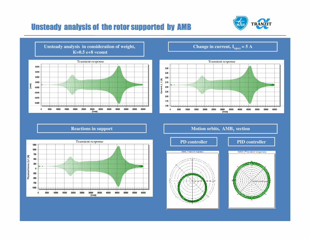
UnsteadyUnsteady analysisanalysis ofof the the rotorrotor supportedsupported byby AMBAMB
Unsteady analysis in consideration of weight,
К=0.5 е+8 =const
Change in current, Iпред = 5 А
-0.020
-0.015
-0.010
-0.005
0.000
0.005
0.010
0.015
0 5000 10000 15000 20000 25000 30000 35000 40000 45000 50000 55000 60000
Transient response
[mm
]
[1/min]
1.50
1.75
2.00
2.25
2.50
2.75
3.00
3.25
3.50
0 5000 10000 15000 20000 25000 30000 35000 40000 45000 50000 55000 60000
Transient response
Cu
rre
nt,
I_1
[A
]
[1/min]
Reactions in support Motion orbits, AMB1 section
-1000
-750
-500
-250
0
250
500
750
1000
1250
0 5000 10000 15000 20000 25000 30000 35000 40000 45000 50000 55000 60000
Transient response
Ph
ys
ica
l fo
rce
, fy
1 [
N]
[1/min]
PD controller PID controller

AMB stiffness and damping controlAMB stiffness and damping control
6000
6500
7000
7500
8000
8500
9000
9500
10000
10500
11000
11500
12000
0 5000 10000 15000 20000 25000 30000 35000 40000 45000 50000 55000 60000
Transient response
Dam
pin
g in
xx d
irection, C
xx [N*s
/m]
[1/min]
AMB damping control
0.5
0.6
0.7
0.8
0.9
1.0
1.1
1.2
1.3
1.4
1.5
1.6
1.7
0 5000 10000 15000 20000 25000 30000 35000 40000 45000 50000 55000 60000
Transient response
Stiff
ness in
xx d
irection, K
xx [N/m
][e8]
[1/min]
AMB stiffness control

The rThe rotorotor dropdowndropdown onon the the journaljournal bearingsbearings
(Steel on babbit) 0.005
(Steel on graphit) 0.1
-1.00
-0.75
-0.50
-0.25
-0.00
0.25
0.50
0.75
1.00
-0.01 -0.00 0.01 0.02 0.03 0.04 0.05 0.06 0.07 0.08 0.09 0.10 0.11
Transient response
[mm
]
[s]
Journal bearing 1 Journal bearing 2
Radial clearance in AMB , mm 0.5
Radial clearance in journal bearing,
mm
0.25
AMB stiffness, N/m 0.5e+8
AMB damping, N s/m 6000
Contact stiffness, N/m 1е+10
-0.15
-0.10
-0.05
0.00
0.05
Transient response
[mm
]
Transition period
Going into
backward precession Backward precession-0.25
-0.20
-0.15
-0.10
-0.05
0.00
-0.01 -0.00 0.01 0.02 0.03 0.04 0.05 0.06 0.07 0.08
Transient response
[mm
]
[s]
-0.25
-0.20
-0.15
-0.10
-0.05
0.00
-0.01 -0.00 0.01 0.02 0.03 0.04 0.05 0.06 0.07 0.08
Transient response
[mm
]
[s]
-0.35
-0.30
-0.25
-0.20
-0.15
0.015 0.016 0.017 0.018 0.019 0.020 0.021 0.022 0.023 0.024
[mm
]
[s]

The rThe rotorotor dropdowndropdown onon the the rollingrolling bearingsbearings
Going into
whirling motion
Bearing 1 Bearing 2
Radial clearance in AMB , mm 0.5
Radial clearance in rolling bearing,
mm
0
Radial clearance between the shaft
and the rolling bearing, mm
0.25
AMB stiffness, N/m 0.5e+8
AMB damping, N s/m 6000
Contact stiffness in rolling bearing,
N/m
1е+10
The rotor stop.
Rotating speed changes from n = 30000 rpm
up to n = 0 rpm
t= 10 s
Movement before
whirling motion
Rotating speed of
inner ring of rolling
bearing
n = 30000 rpm
-0.30
-0.25
-0.20
-0.15
-0.10
-0.05
0.00
0.05
-0.02 -0.01 -0.00 0.01 0.02 0.03 0.04 0.05 0.06 0.07 0.08 0.09 0.10 0.11 0.12 0.13 0.14 0.15
Transient response
[mm
]
[s]
-0.30
-0.25
-0.20
-0.15
-0.10
-0.05
0.00
-0.02 -0.01 -0.00 0.01 0.02 0.03 0.04 0.05 0.06 0.07 0.08 0.09 0.10 0.11 0.12 0.13 0.14 0.15
Transient response
[mm
]
[s]
Full-clearance motion Following stop

The general methodology of designing the rotor The general methodology of designing the rotor
supported by AMBsupported by AMB
Determination of necessary values of AMB stiffness and damping
Determination of the rotor’s damped critical speeds and mode shapes – places of prospective resonances
Calculation of forced oscillations and amplitude values of vibroparameters : displacements, vibrovelocity,
reactions in supporting units. etc.
Estimation of AMB control coefficients and adjustment of the control system
Development of the program of current – AMB stiffness and damping – control for passing systems
resonances and going into the operating range
characteristics at transient regimes
Unsteady analysis of the rotor supported by AMB with the aim of more precise definition of the rotor’s
characteristics at transient regimes
Simulation of the rotor supported by backup bearings. The non-linear unsteady rotor analysis. The aim is to
determine the possibility of the rotor’s going into whirling motion or backward precession
The unsteady rotor analysis after switching off AMB supported by non-linear rolling bearings while the rotor’s
deceleration and determination of resonance regimes

THANK YOU FOR
YOUR ATTENTION!


