Notice
Note that when converting this document from its original format to a .pdf file, some minor font and format changes may occur. When viewing and printing this document, we cannot guarantee that your specific PC or printer will support all of the fonts or graphics. Therefore, when you view the document, fonts may be substituted and your individual printer may not have the capability to print the document correctly.


RESOURCE MANUAL
INT-2068 (GEN)Issue 1.0
DT700


NEC Unified Solutions, Inc. reserves the right to change the specifications, functions, or features atany time without notice.
NEC Unified Solutions, Inc. has prepared this document for use by its employees and customers. Theinformation contained herein is the property of NEC Unified Solutions, Inc. and shall not be reproducedwithout prior written approval of NEC Unified Solutions, Inc.
Dterm is a registered trademark of NEC Corporation and UNIVERGE is a trademark of NECCorporation. Windows is a registered trademark of Microsoft Corporation. AT&T is a registeredtrademark of American Telephone and Telegraph Company. Lucent Technologies is a trademark orservice mark of Lucent Technologies Inc. Nortel Networks and the Nortel Networks logo aretrademarks of Nortel Networks. Verizon Wireless is a trademark of Verizon Trademark Services, LLC.All other brand names and product names referenced in this document are trademarks or registeredtrademarks of their respective companies.
Copyright 2008
NEC Infrontia, Inc.6535 N. State Highway 161
Irving, TX 75039-2402
Technology Development


DT700 Resource Manual i
___________________________________________________________________________________
___________________________________________________________________________________
Table of Contents
Chapter 1 ITL Terminal AutoConfig Setup
Section 1 Introduction......................................................................................................... 1-1
Section 2 DHCP Setup and Configuration ......................................................................... 1-2
Section 3 AutoConfiguration Application File Setup......................................................... 1-13
Section 4 AutoConfig Setup Example .............................................................................. 1-19
4.1 Required Equipment ............................................................................. 1-19
4.2 Building the Configuration File .............................................................. 1-19
4.3 Configuring a FTP Server ..................................................................... 1-23
4.4 DHCP Server Setup Windows 2003 Server Example .......................... 1-26
Chapter 2 IP Phone Manager
Section 1 Installation .......................................................................................................... 2-1
Section 2 Searching for Terminals ..................................................................................... 2-3
2.1 Terminal Connection .............................................................................. 2-6
Section 3 IP Phone Manager Commands ........................................................................ 2-7
Chapter 3 XML Applications
Section 1 Introduction......................................................................................................... 3-1
1.1 System Requirements ............................................................................ 3-1
Section 2 Installation Setup................................................................................................ 3-2

ii Table of Contents
___________________________________________________________________________________
___________________________________________________________________________________ Issue 1.0 DT700
2.1 XML Application Setup ........................................................................... 3-2
Section 3 XML Suite Web Configuration.......................................................................... 3-10
3.1 Administer Login ................................................................................... 3-10
3.2 XML Terminal ...................................................................................... 3-28
3.2.1 Terminal Configuration Setup .............................................................. 3-28
3.2.2 Terminal Web Configuration ................................................................ 3-29
3.2.3 Enable XML Application on the XML Terminal .................................... 3-31
3.2.4 Terminal Display Screens .................................................................... 3-32
Chapter 4 Download Ring Tones and MOH
Section 1 Ring Tone Specifications ................................................................................... 4-1
1.1 Ring Tone – Format Specifications ........................................................ 4-1
1.2 Ring Tone Upload Procedure ................................................................. 4-2
1.3 Terminal Ring Tone Setting .................................................................... 4-5
Section 2 Music On Hold (MOH) Tone Format .................................................................. 4-6
2.1 MOH Upload Procedure ......................................................................... 4-6
2.2 Terminal MOH Setting ............................................................................ 4-9
Chapter 5 DT Archiver
Section 1 DT Archiver Introduction .................................................................................... 5-1
1.1 Creating Compressed Files .................................................................... 5-1
1.2 Decompressing Files .............................................................................. 5-2

DT700 Resource Manual iii
___________________________________________________________________________________
___________________________________________________________________________________
LIST OF FIGURES
Figure 1-1 Network Operation and Topology ..................................................................................1-1
Figure 1-2 Selecting Server ............................................................................................................1-2
Figure 1-3 Defining Vendor Class ...................................................................................................1-3
Figure 1-4 Enter Name ...................................................................................................................1-3
Figure 1-5 Select Server .................................................................................................................1-4
Figure 1-6 Select Option Class .......................................................................................................1-5
Figure 1-7 Add NEC Option Codes ................................................................................................1-5
Figure 1-8 141 FTP Server Settings ...............................................................................................1-6
Figure 1-9 151 File Name Settings .................................................................................................1-6
Figure 1-10 163 Protocol Settings ....................................................................................................1-7
Figure 1-11 Scope Options ...............................................................................................................1-7
Figure 1-12 Scope Options - Advanced ............................................................................................1-8
Figure 1-13 Scope Advanced Tab – FTP IP Address .......................................................................1-9
Figure 1-14 Scope Advanced Tab – File Name ..............................................................................1-10
Figure 1-15 Scope Advanced Tab – FTP Byte Data ......................................................................1-11
Figure 1-16 Vendor Options Available to DT700 IP Terminals .......................................................1-12
Figure 1-17 Home Screen ..............................................................................................................1-13
Figure 1-18 Configuration Screen ...................................................................................................1-14
Figure 1-19 Manual Version Entry ..................................................................................................1-15
Figure 1-20 Data Entry Field Screen ..............................................................................................1-16
Figure 1-21 Save Screen ................................................................................................................1-17
Figure 1-22 Data Restore Screen ...................................................................................................1-18
Figure 1-23 Build Configuration File – Auto Config Tab .................................................................1-19
Figure 1-24 Build Configuration File – Select Terminal ..................................................................1-20
Figure 1-25 Build Configuration File – Select Server IP Address/Server Port ................................1-20

Issue 1.0 DT700___________________________________________________________________________________
iv List of Figures
___________________________________________________________________________________
Figure 1-26 Build Configuration File – Assign 1st Server Address .................................................1-21
Figure 1-27 Build Configuration File – Assign 1st Server Port ........................................................1-21
Figure 1-28 Build Configuration File – Save Config Setup File .......................................................1-22
Figure 1-29 Anonymous FTP Server Configuration Settings Example ...........................................1-23
Figure 1-30 Anonymous FTP Server Configuration Settings Example – Advanced Tab ................1-24
Figure 1-31 Anonymous FTP Server Configuration Settings Example – Default Home Directory ......................................................................................................................1-25
Figure 2-1 Select Interface Screen .................................................................................................2-1
Figure 2-2 IP Phone Manger Screen ..............................................................................................2-2
Figure 2-3 Searching for Terminals ................................................................................................2-3
Figure 2-4 Input IP Address Screen ................................................................................................2-4
Figure 2-5 Import File Screen .........................................................................................................2-5
Figure 2-6 Terminal Connection Screen .........................................................................................2-6
Figure 2-7 IP Phone Manager Commands Screen .........................................................................2-7
Figure 2-8 Switch Port Control Screen ...........................................................................................2-8
Figure 2-9 Terminal Reset Screen ..................................................................................................2-9
Figure 2-10 SecurityLock Feature Screen ......................................................................................2-10
Figure 2-11 Data Reset Screen ......................................................................................................2-11
Figure 2-12 Download Option Screen .............................................................................................2-12
Figure 2-13 Backup/Restore Screen ...............................................................................................2-13
Figure 2-14 Error Log Screen .........................................................................................................2-14
Figure 2-15 Config Application Screen ...........................................................................................2-15
Figure 3-1 XML Application Setup – Download and Unzip .zip File ................................................3-2
Figure 3-2 XML Application Setup – Begin Installation ...................................................................3-3
Figure 3-3 XML Application Setup – Installation Status ..................................................................3-3
Figure 3-4 XML Application Setup – SQL Server Express Installation ...........................................3-4
Figure 3-5 XML Application Setup – XML Application Suite Installation .........................................3-5
Figure 3-6 XML Application Setup – XML Application Setup Wizard ..............................................3-6
Figure 3-7 XML Application Setup – Software License Agreement ................................................3-7

DT700 Issue 1.0
DT700 Resource Manual - v
___________________________________________________________________________________
___________________________________________________________________________________
DT700 Resource Manual v
___________________________________________________________________________________
Figure 3-8 XML Application Setup – Select Installation Folder Location ........................................3-8
Figure 3-9 XML Application Setup – Installation Complete ............................................................3-9
Figure 3-10 XML Suite Web Configuration – Login Form ...............................................................3-10
Figure 3-11 XML Suite Web Configuration – Administrator Login Home Page ..............................3-11
Figure 3-12 XML Suite Web Configuration – Administrator Page ..................................................3-12
Figure 3-13 XML Suite Web Configuration – User List ...................................................................3-14
Figure 3-14 XML Suite Web Configuration – Add User ..................................................................3-15
Figure 3-15 XML Suite Web Configuration – User Login ................................................................3-17
Figure 3-16 XML Suite Web Configuration – Home Page ..............................................................3-18
Figure 3-17 XML Suite Web – Subscribe Page ..............................................................................3-19
Figure 3-18 XML Suite Web – Alarm Clock ....................................................................................3-20
Figure 3-19 XML Suite – Weather ..................................................................................................3-21
Figure 3-20 XML Suite – Photo Album ...........................................................................................3-22
Figure 3-21 XML Suite – Outlook Integration .................................................................................3-23
Figure 3-22 XML Suite – Icon in System Tray ................................................................................3-23
Figure 3-23 XML Suite – Sync Application installation ...................................................................3-24
Figure 3-24 XML Suite – Application Outlook Sync ........................................................................3-25
Figure 3-25 XML Suite – Profile Page ............................................................................................3-26
Figure 3-26 XML Suite – Logout Page ...........................................................................................3-27
Figure 3-27 Terminal Web Configuration – Login Page .................................................................3-29
Figure 3-28 Terminal Web Configuration – Assign Home URL ......................................................3-30
Figure 3-29 Enable XML Application on Terminal ..........................................................................3-31
Figure 3-30 Enable XML Application – Enter PIN ...........................................................................3-31
Figure 3-31 Terminal Display Screen – Home ................................................................................3-32
Figure 3-32 Terminal Display Screen – System .............................................................................3-32
Figure 3-33 Terminal Display Screen – Clock & Calendar .............................................................3-33
Figure 3-34 Terminal Display Screen – Alarm ................................................................................3-34
Figure 3-35 Terminal Display Screen – Weather Display ...............................................................3-35
Figure 3-36 Terminal Display Screen – Weather Zip Code Assignment ........................................3-35

Issue 1.0 DT700___________________________________________________________________________________
vi List of Figures
___________________________________________________________________________________
Figure 3-37 Terminal Display Screen – Photo Album Display ........................................................3-36
Figure 4-1 Ring Tone Upload – Save to Local Directory ................................................................4-2
Figure 4-2 Ring Tone Upload – Start TFTP/FTP on PC .................................................................4-2
Figure 4-3 Ring Tone Upload – Point TFTP/FTP to Ring Tone File ...............................................4-3
Figure 4-4 Ring Tone Upload – Enter File Name ............................................................................4-4
Figure 4-5 Ring Tone Terminal Settings .........................................................................................4-5
Figure 4-6 Music on Hold – Save to Local Directory on PC ............................................................4-6
Figure 4-7 Music on Hold – Start TFTP/FTP on PC .......................................................................4-7
Figure 4-8 Music on Hold – Point TFTP/FTP to Ring Tone File .....................................................4-7
Figure 4-9 Music on Hold – Enter File Name ..................................................................................4-8
Figure 4-10 Music on Hold – Download ............................................................................................4-9
Figure 4-11 Sound Recorder – Start Program ................................................................................4-10
Figure 4-12 Sound Recorder – Sound Selection ............................................................................4-10
Figure 5-1 DT Archiver – Compress Files .......................................................................................5-1
Figure 5-2 DT Archiver – Decompress Files ...................................................................................5-2

DT700 Resource Manual 1 - 1
ITL
Term
ina
l Au
toC
on
fig S
etu
p
1ITL Terminal AutoConfig Setup
SECTION 1 INTRODUCTION
This chapter describes the operation of the Auto Configuration File Application for DT700 series terminals.
Refer to Figure 1-1 Network Operation and Topology and the steps that follow to describe the process that the DT700 terminal uses to automatically configure itself using common network devices (Plug and Play).
Figure 1-1 Network Operation and Topology

Issue 1.0 DT700
1 - 2 ITL Terminal AutoConfig Setup
1. Use the AutoConfiguration Application to create a terminal configuration file with corresponding network and telephony data parameters that are needed to connect the DT700 IP Terminal to the Telephony Switch. This created AutoConfiguration file needs to be loaded onto a network accessible PC/Server with a FTP server running.
2. Plug the DT700 Series Terminal into the local network (Factory Value Settings).
3. Local DHCP server provides Vendor Specific Options for the DT700 IP terminal.
4. The DT700 IP Terminal uses the DHCP Vendor Specific Options to communicate with the local FTP Server
5. The DT700 terminal downloads the created AutoConfig file from the FTP Server.
6. The DT700 terminal initializes with its new downloaded configuration settings, and connects to the Telephony Switch.
SECTION 2 DHCP SETUP AND CONFIGURATION
1. Left click on the Server to be used.
Figure 1-2 Selecting Server

DT700 Issue 1.0
DT700 Resource Manual 1 - 3
2. From the Drop Down list, select Define Vendor Class and select Add.
3. At the New Class Window, enter NECDT700 in the Display Name field and under the ASCII setting.
Figure 1-3 Defining Vendor Class
Figure 1-4 Enter Name

Issue 1.0 DT700
1 - 4 ITL Terminal AutoConfig Setup
4. Select OK to save the settings.
5. Select Close to exit Vendor Name Setup.
6. Left click on the Server used and select Set Predefined Opinions.
Figure 1-5 Select Server

DT700 Issue 1.0
DT700 Resource Manual 1 - 5
7. In Option Class, select NECDT700.
8. Select Add to configure NEC option codes.
Figure 1-6 Select Option Class
Figure 1-7 Add NEC Option Codes

Issue 1.0 DT700
1 - 6 ITL Terminal AutoConfig Setup
9. AutoConfiguration requires three separate, unique NEC option codes to be set:141 FTP Server – Network Server that the AutoConfiguration file will be saved.
Enter an option code name (FTP Address) in the name Field. Set the Data Type field to IP Address, enter the IP Address of the FTP server PC and enter 141 in the Code Field. Select OK to save the settings.
151 File Name – Saved name of the AutoConfiguration file. Select Add to enter the next NEC option code.
Enter an option code name (AutoConfig File) in the name Field. Set the Data Type field to String, and enter 151 in the Code Field. Select OK to save the settings.
Figure 1-8 141 FTP Server Settings
Figure 1-9 151 File Name Settings

DT700 Issue 1.0
DT700 Resource Manual 1 - 7
163 Protocol – This transmission is used (FTP). Select Add to enter the 3rd NEC option code. Enter an option code name (Protocol) in the name Field. Set the Data Type field to Byte, and enter 163 in the Code Field. Select OK to save the settings.
10. Left click Scope Options and select Configure Options to configure each defined NEC option codes.
Figure 1-10 163 Protocol Settings
Figure 1-11 Scope Options
Issue 1.0 DT700
1 - 8 ITL Terminal AutoConfig Setup
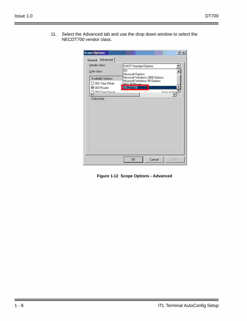
11. Select the Advanced tab and use the drop down window to select the NECDT700 vendor class.
Figure 1-12 Scope Options - Advanced

DT700 Issue 1.0
DT700 Resource Manual 1 - 9
12. Check options 141, 151 and 163:141 – Enter the IP Address of the FTP server and press Apply.
Figure 1-13 Scope Advanced Tab – FTP IP Address

Issue 1.0 DT700
1 - 10 ITL Terminal AutoConfig Setup
151 – Enter the File Name of the saved AutoConfiguration File and press Apply.
Figure 1-14 Scope Advanced Tab – File Name

DT700 Issue 1.0
DT700 Resource Manual 1 - 11
163 – Enter 0x1 for FTP Byte data and press Apply.
Figure 1-15 Scope Advanced Tab – FTP Byte Data

Issue 1.0 DT700
1 - 12 ITL Terminal AutoConfig Setup
13. The created Vendor Options should now be offered to the DT700 IP Terminals when connected to the Local Network.
Figure 1-16 Vendor Options Available to DT700 IP Terminals

DT700 Issue 1.0
DT700 Resource Manual 1 - 13
SECTION 3 AUTOCONFIGURATION APPLICATION FILE SETUP
Home ScreenFrom the Home Screen, you can either create a new Config File, or Modify an existing File.
1. Select User Language.
2. Under New File, select the type of file to create:Terminal allows the user to set terminal configuration data
Network SettingsSIP SettingsMaintenance SettingsSecurityApplicationSpecial
Figure 1-17 Home Screen
1
2
3
Issue 1.0 DT700
1 - 14 ITL Terminal AutoConfig Setup
Personal allows for the configuration of personal data• User Settings• Downloads• Backup and Restore
3. File Open allows you to import and modify an existing file.
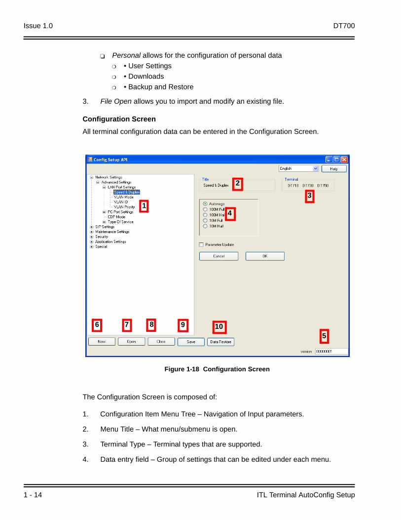
Configuration ScreenAll terminal configuration data can be entered in the Configuration Screen.
The Configuration Screen is composed of:
1. Configuration Item Menu Tree – Navigation of Input parameters.
2. Menu Title – What menu/submenu is open.
3. Terminal Type – Terminal types that are supported.
4. Data entry field – Group of settings that can be edited under each menu.
Figure 1-18 Configuration Screen
1
23
4
56 7 8 9 10

DT700 Issue 1.0
DT700 Resource Manual 1 - 15
5. Configuration File Version Number.
6. New – return to the Home Screen to create a new configuration file.
7. Open – Allows user to open an existing file.
8. Close – Ends the Auto Config Setup Application Session.
9. Save – Save the current open file to a desired location.
10. Data Restore – Restores Modified Data settings to previous saved or default entries.
DT700 series terminals use the Version revision number to compare internal terminal file and FTP server file versions during the Plug and Play process. If the terminal does not have the same version number as the stored FTP server, the terminal downloads the FTP configuration file version. Version number is automatically updated when a file is modified, or the version number can be entered manually.
Figure 1-19 Manual Version Entry
Manual Entry

Issue 1.0 DT700
1 - 16 ITL Terminal AutoConfig Setup
Data Entry FieldUse the Data Entry Field to enter all required values for the Menu Tree option that has been selected.
1. Data Entry – Select a Menu Tree Option, and enter the required data.
2. Parameter Update – Build a unique Configuration File to update only the selected Parameter items that have changed.
3. Cancel – Cancels the Data value change and returns to the previous setting.
4. OK – Temporarily save data entry to the configuration file.
Figure 1-20 Data Entry Field Screen
1
2
3
4

DT700 Issue 1.0
DT700 Resource Manual 1 - 17
Save ScreenUse Save to help control the Configuration File.
File Type
Save Selected – this option merges only the selected Parameter Update items in the selected Configuration File.
Save All – This selection builds a completely new Configuration File.
File Name
If an existing file was imported for editing or previously saved, the name is displayed.
If the current file was not previously saved, this field is empty.
File Revision
File Revision shows the Version number of the file that is saved.
This number is used by the DT700 terminal to compare the current configuration to one that is located on the FTP server.
Figure 1-21 Save Screen

Issue 1.0 DT700
1 - 18 ITL Terminal AutoConfig Setup
Cancel
Terminates the save process and returns to the Configuration Screen.
Save
Saves the settings of the configuration file.
Save As
Allows the user to specify parameters and the location of the file to be saved.
Data Restore Screen
The Data Restore screen allows the modified configuration file to return to a previoussetting.
The Data Field window shows the File name and previous File Revision Version that the current modified file converts back to.
Use Cancel or OK to execute the applicable task.
Figure 1-22 Data Restore Screen

DT700 Issue 1.0
DT700 Resource Manual 1 - 19
SECTION 4 AUTOCONFIG SETUP EXAMPLE
4.1 Required Equipment
The following is a list of required equipment for the AutoConfig for the SV8100 IP Terminals.
IP Phone ManagerFree software available for download on NEC website. This software is used to create the configuration file for the IP terminals.
FTP ServerFree software available on the Web.
DHCP ServerThis Dynamic Host Configuration Protocol (DHCP) server must define a Vendor Class. The DHCP server must also define Option Codes.
4.2 Building the Configuration File
1. Launch the IP Phone Manager software.
Figure 1-23 Build Configuration File – Auto Config Tab
Once the software is launched, click on the Auto Config tab.
Issue 1.0 DT700
1 - 20 ITL Terminal AutoConfig Setup
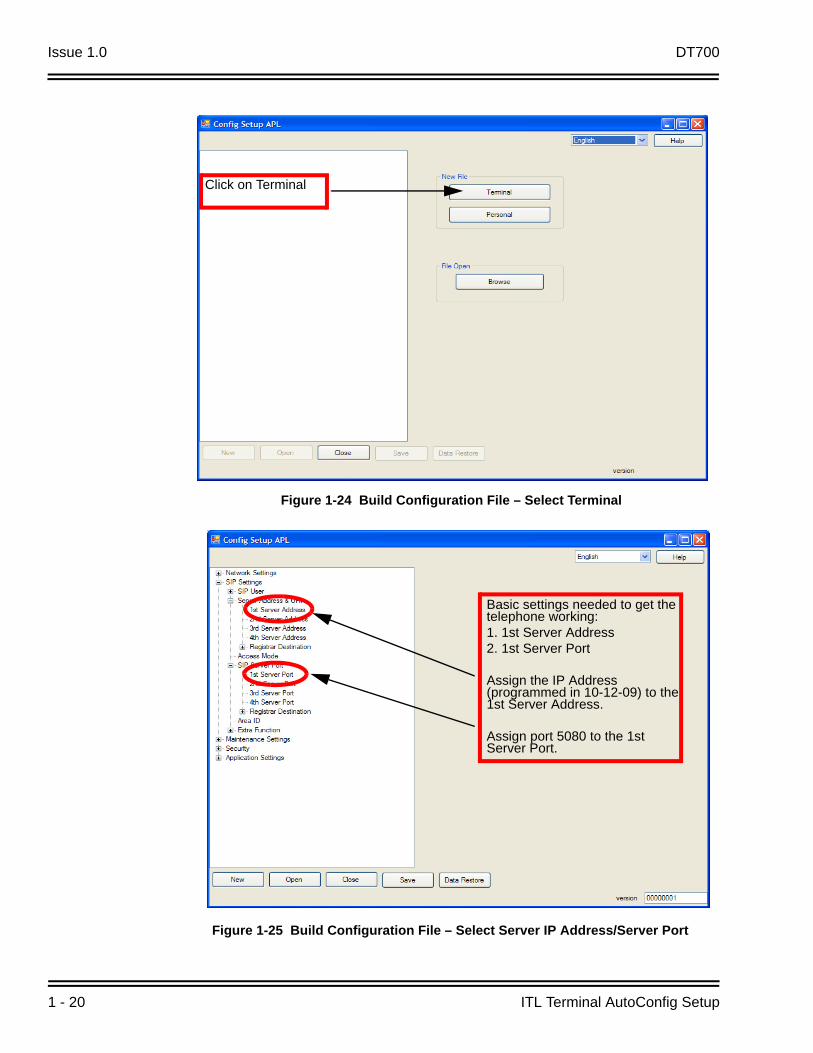
Figure 1-24 Build Configuration File – Select Terminal
Figure 1-25 Build Configuration File – Select Server IP Address/Server Port
Click on Terminal
Basic settings needed to get the telephone working:1. 1st Server Address2. 1st Server Port
Assign the IP Address (programmed in 10-12-09) to the 1st Server Address.
Assign port 5080 to the 1st Server Port.

DT700 Issue 1.0
DT700 Resource Manual 1 - 21
1. Click on the 1st Server Address to bring up the window shown on the right side of screen.
2. Assign the IP Address.
3. Click OK to finish.
Figure 1-26 Build Configuration File – Assign 1st Server Address
Figure 1-27 Build Configuration File – Assign 1st Server Port
1 2
3
1
2
3

Issue 1.0 DT700
1 - 22 ITL Terminal AutoConfig Setup
1. Click on the 1st Server Port to bring up the window shown on the right side of screen.
2. Assign the Port number.
3. Click OK to finish.
1. After the changes are made, click on Save.
2. The Save window then opens. Click on Save as...The file must now be named. Name the file as xxx.gz (Example: test.gz).
The file must then be placed in the FTP Server.
Figure 1-28 Build Configuration File – Save Config Setup File
1
2

DT700 Issue 1.0
DT700 Resource Manual 1 - 23
4.3 Configuring a FTP Server
The FTP Server must be configured with an anonymous login account. The file generated from the IP Phone Manager must be placed in the anonymous login folder.
The example below shows the Quick and Easy FTP Server:
1. Click Configure Settings.
Figure 1-29 Anonymous FTP Server Configuration Settings Example
1

Issue 1.0 DT700
1 - 24 ITL Terminal AutoConfig Setup
2. Click the Advanced tab to specify the directory where files are stored.
Figure 1-30 Anonymous FTP Server Configuration Settings Example – Advanced Tab
2

DT700 Issue 1.0
DT700 Resource Manual 1 - 25
3. Place the file (for example:test.gz) into the default home directory.
4. Once the file is loaded in the directory, start the FTP Server by clicking Start.The FTP Server can be minimized to run in the background.
Figure 1-31 Anonymous FTP Server Configuration Settings Example – Default Home Directory
3
4

Issue 1.0 DT700
1 - 26 ITL Terminal AutoConfig Setup
4.4 DHCP Server Setup Windows 2003 Server ExampleIn the DHCP server highlight the server machine on the left hand side. Right click on the server and choose Define Vendor Classes.Click ADDDisplay Name = NECDT700Description = auto configIn the same window down below there is a section that shows ID, Binary, and ASCII. Click in that window under ASCII. Now enter NECDT700. This should have also added 4E 45 43 44 54 37 30 30 under the binary section. Now click on OK and close.Highlight the server again then right click and choose Set Predefined Options.Change the option class to NECDT700.Click ADD and give the following infoName = FTP AddressData Type = IP addressCode = 141Click on OK, and start the process over againClick on ADD and give the following infoName = Auto Config File NameData Type = StringCode = 151Click on ADD and give the following infoName = Download ProtocolData Type = ByteCode = 163Click OK
Highlight scope options on the left hand side then right click and choose Configure Options.Click Advanced, and change the vendor class to NECDT700.Place a check mark next to 141 FTP Address. Down below assign the IP address of the FTP server then click applyPlace a check mark next to 151 auto config file name. Down below type the name of the config file that was built via IP phone manager. Then click apply.Ex. Test.gzPlace a check mark next to 163 download protocol. Down below change the HEX address to be 0x1.Click apply and OK.
Setting up a DHCP server to just send the port number along with the SIP server address.
In the DHCP server right click Scope Options.Go to Configure OptionsScroll down to Option 43 Vendor Specific Information.Put a check mark next to this and it brings up a window below.In the data field below delete the 00 and add the following: A8 02 13 DBA8 = 168 this is sub-option 168 in option 4302 = When using this sub-option the first byte must be 0213 DB = port 5080Click ApplyScroll down to Option 120 Sip Server.Put a check mark next to this and it brings up a window below.

DT700 Issue 1.0
DT700 Resource Manual 1 - 27
In the data field below delete the 00 and add the following: 01 AC 10 00 0A (IP address in Hex with a 1 in the front meaning 1st SIP server).01 = First sip serverAC = 17210 = 1600 = 00A = 10So this is sending 01 172.16.0.10 (IP address of SIP server)Click APPLY and OK

Issue 1.0 DT700
1 - 28 ITL Terminal AutoConfig Setup
- - NOTES - -

DT700 Resource Manual 2 - 1
IP P
ho
ne
Ma
na
ge
r
2IP Phone Manager
SECTION 1 INSTALLATION
Follow these steps for installation of the IP Phone Manager.
1. Double Click Setup.exe icon to initiate the installation.
2. After installation, a Shortcut is placed on your PC Desktop. This icon can be used to run the IP Phone Manager application.
3. At the elect Interface Pop Up, select the active Network Interface Card that your PC is currently using.
Figure 2-1 Select Interface Screen
IPPhoneManager.lnk

Issue 1.0 DT700
2 - 2 IP Phone Manager
4. IP Phone Manager now opens on your PC.
Figure 2-2 IP Phone Manger Screen

DT700 Issue 1.0
DT700 Resource Manual 2 - 3
SECTION 2 SEARCHING FOR TERMINALS
Three methods search for active terminals on your network.
1. Search
The IP Phone manager sends a broadcast over the network in search of terminals. Active terminals respond to this broadcast with terminal information.
There are three settings that change the Search Frequency and timing of the IP Phone Manager broadcast.
Figure 2-3 Searching for Terminals
1 2
3

Issue 1.0 DT700
2 - 4 IP Phone Manager
2. Direct
When an IP Address of the terminal is known, it is possible to search for it independently. This is commonly used to for a quick search of a specific terminal or a terminal that may be in a different network or subnet.
3. Import
PBX System configuration applications may export a list of registered terminals in a CSV file format. This CSV file can be imported to the IP Phone Manager Application. This import can now be used to Search and Connect the registered terminals indicated in the imported file.
The IP Phone Manager allows an active list of terminals to be exported in CSV format for later import or to save a current database for examination.
Figure 2-4 Input IP Address Screen

DT700 Issue 1.0
DT700 Resource Manual 2 - 5
Figure 2-5 Import File Screen

Issue 1.0 DT700
2 - 6 IP Phone Manager
2.1 Terminal Connection
After terminals are discovered by the IP Phone Manger Search functionality, they must be connected before any action can take place. For terminals that need maintenance or further information communicated between them, select the check box and press Connect. When the Status Field indicates OK, the terminal is in active communication with IP Phone Manager.
Figure 2-6 Terminal Connection Screen

DT700 Issue 1.0
DT700 Resource Manual 2 - 7
SECTION 3 IP PHONE MANAGER COMMANDS
Figure 2-7 IP Phone Manager Commands Screen

Issue 1.0 DT700
2 - 8 IP Phone Manager
1. SwitchPortCtrl
Switch Port Control can enable or disable the PC Port on the connected IP Terminal(s).
Figure 2-8 Switch Port Control Screen

DT700 Issue 1.0
DT700 Resource Manual 2 - 9
2. Reset
This function resets the terminal(s) connected to the IP Phone Manager. Two options for resetting the Connected terminal(s) are available:
Soft Reset – Application layer of the terminal
Hard Reset – Full hardware initialization of the terminal
3. SecurityLock
This feature can lock or unlock the Connected Terminal(s), and has two modes:
Enable allows the user to change the status of the terminal security.
All Clear – Returns the terminal password to default value
Unlock – One-time security release on the terminal
Lock – Locks the Connected terminal(s)
Disable disables the SecurityLock feature from being set from the terminal.
Figure 2-9 Terminal Reset Screen

Issue 1.0 DT700
2 - 10 IP Phone Manager
Figure 2-10 SecurityLock Feature Screen

DT700 Issue 1.0
DT700 Resource Manual 2 - 11
4. Data Reset
Data Reset erases the configuration stored in terminal memory. Three terminal memory locations can be reset.
IP Phone Settings – Terminal Configuration Data that is set in terminal programming under the Config menu tree
Personal Settings
Personal Data – Data that the user has personally set (holding tone, ring tone, and telephone book)
Factory Default – Resets all three Data Settings.
Figure 2-11 Data Reset Screen

Issue 1.0 DT700
2 - 12 IP Phone Manager
5. Download
This feature downloads various file types via a FTP/TFTP server. Select the server type to be used for downloads and the parameters that are required (IP Address of server, authentication name and passwords).
Download Option:
Use the Download Option Field to select the Terminal File type and enter a File name as required.
Use the Simultaneous Downloads to select the quantity of terminals that access and attempt downloads at the same time. All remaining terminals are put into queue for the next available spot. Some server applications can handle only limited simultaneous connections – consult your server documentation for any limitations.
IP Phone Information:IP Phone Information is a search tool to help organize a large database of terminals into more manageable groupings. Terminals can be grouped in categories by Type, Hardware Version, or Firmware Version.
Figure 2-12 Download Option Screen

DT700 Issue 1.0
DT700 Resource Manual 2 - 13
6. Backup & Restore
Backup and Restore functionality allows terminal data to be sent to or received from a network server.
Data Backup is used to copy the current terminal data and configuration to an FTP/TFTP server for archiving. File names for the restored data can be saved as the terminal MAC address, IP Address or Extension number for easy user management.
Data Restore is used to copy a preexisting archived file to a terminal to restore its previous settings.
Simultaneous Download can be selected according to the limitations of the FTP/TFTP server that you have selected to use.
Figure 2-13 Backup/Restore Screen

Issue 1.0 DT700
2 - 14 IP Phone Manager
7. Error Log
Error Log information is a useful tool that can be used by developers for troubleshooting. Terminal log information can backup an FTP/TFTP server and is saved under the terminal MAC Address, IP Address or Extension number of the selected terminal(s).Simultaneous Download can be selected according to the limitations of the FTP/TFTP server that you have selected to use.
Figure 2-14 Error Log Screen

DT700 Issue 1.0
DT700 Resource Manual 2 - 15
Config Application
1. Web Config
The IP terminal has an HTTP server for web programming. Selecting this button starts a session with Internet Explorer (or the default web browser installed on the local PC) for all the connected and selected terminals. You have one browser session started for every selected terminal – this feature is used on an individual terminal.
2. Auto Config
The Auto Config button is a direct link to the Auto Configuration Tool. Auto Configuration Tool is used to build a master terminal configuration file for terminal initial setup Plug and Play purposes. Consult the Auto Configuration manual for detailed setup and configuration options.
Figure 2-15 Config Application Screen
21

Issue 1.0 DT700
2 - 16 IP Phone Manager
Toolbar Features1. Search – Sets the frequency and timing that the IP Phone Manager attempts to
search and discover IP terminals on the network.
2. Port Set – Port Set allows the customization for Port Numbers that the IP Phone Manager Application and IP Terminals use for communication.
Default IP Phone = 3530
IP Phone Manager = 20111
3. Interface – Select or change the active PC NIC card that IP Phone Manager needs to use.
4. ListCtrl – List Control is used to select and organize the fields to be viewed in the active IP Phone Manager home layout screen.
Select
5. Help – Displays Version information of IP Phone Manager.
6. Select ALL – Selects ALL discovered terminals.
7. Clear ALL – Unselects all preselected terminals on the home screen.
8. Quit – Terminates all communication between IP Phone Manager and closes the application.

DT700 Resource Manual 3 - 1
XM
L A
pp
licatio
ns
3XML Applications
SECTION 1 INTRODUCTION
The NEC XML-Application is a service that provides user specific content to NEC DT700 terminals.
Services that are provided for each DT700 user include:
Display analog clock and calendar indicating today
Weather for a maximum of three zip codes specified by the user
Photo album where user can upload photographs, which will be cycled on the terminal display
Display Outlook address book
Display Outlook Calendar appointments
1.1 System Requirements
System requirements include:
The application is assumed to be hosted by the organization as an intranet application.
XML phones (the application on the phone should have HTTP access to the web server)
ASP.NET 2.0 for the web application and SQL Server Express 2005 for the database are required.
Microsoft Internet Information Service 6.0 – IIS installed
32-bit CPU, 1.6GHz with a minimum 1GB RAM and 40GB Hard Drive
Windows XP Professional

Issue 1.0 DT700
3 - 2 XML Applications
SECTION 2 INSTALLATION SETUP
2.1 XML Application Setup
The provided Windows installer installs and creates both the SQL Server Express, SQL Database and the Web Configuration Application.
1. Download and unzip the XML-AppSuite.zip file.
Figure 3-1 XML Application Setup – Download and Unzip .zip File

DT700 Issue 1.0
DT700 Resource Manual 3 - 3
2. To begin installation, click Next.
3. The NEC XML Application Suite Setup begins. Installation time varies, depending on CPU abilities.
Figure 3-2 XML Application Setup – Begin Installation
Figure 3-3 XML Application Setup – Installation Status

Issue 1.0 DT700
3 - 4 XML Applications
4. The NEC Application Installer automatically installs SQL Server Express (if not previously installed on the local PC).
Figure 3-4 XML Application Setup – SQL Server Express Installation

DT700 Issue 1.0
DT700 Resource Manual 3 - 5
5. Double-click the XmlPhone.exe file, setup begins. Click Next>.
Figure 3-5 XML Application Setup – XML Application Suite Installation

Issue 1.0 DT700
3 - 6 XML Applications
6. Select Next> on the Install Wizard to start installation.
Figure 3-6 XML Application Setup – XML Application Setup Wizard

DT700 Issue 1.0
DT700 Resource Manual 3 - 7
7. Select I Agree and press Next> to the accept the Software License Agreement.
Figure 3-7 XML Application Setup – Software License Agreement

Issue 1.0 DT700
3 - 8 XML Applications
8. Browse the location for files to be installed on the local PC (using the default location is recommended).
Figure 3-8 XML Application Setup – Select Installation Folder Location

DT700 Issue 1.0
DT700 Resource Manual 3 - 9
9. Installation Complete is displayed when all components are completely installed.
Make sure proper firewall, and sharing properties are configured to allow access to the IIS and XML Suite Webpages.
Figure 3-9 XML Application Setup – Installation Complete

Issue 1.0 DT700
3 - 10 XML Applications
SECTION 3 XML SUITE WEB CONFIGURATION
3.1 Administer Login
An administrator account is preset during installation. The Administrator is responsible for the addition, basic setup and maintenance of all the User Accounts. Access the Administrator Account by using Internet Explorer and the following URL:
http://localhost/xmlphone/WebLogin.aspx
Localhost can be used if accessing the Web Page from a local PC where XML Suite has been installed. When accessing the Administrator Web Configuration Page remotely, localhost must be replaced with the IP Address of the PC where the XML Suite was installed.
If accessing the Administrator Web Configuration from a remote PC, all proper network connectivity must be maintained.
1. At the XML Application Suite Home Login page enter:
Administrator Login : Admin
Administrator PIN : 12345
2. Press Submit to login to the XML Application Suite.
Figure 3-10 XML Suite Web Configuration – Login Form

DT700 Issue 1.0
DT700 Resource Manual 3 - 11
The Administrator Login Home Page has five configuration tabs.
Home – navigates from current screen back to the Home Page
Subscribe – Enables XML content to be displayed on the DT750 terminal
Profile – Displays user account information
Administration – Administration of user accounts and System, Dial Plan information
Logout – Current user logout
Figure 3-11 XML Suite Web Configuration – Administrator Login Home Page
Issue 1.0 DT700
3 - 12 XML Applications
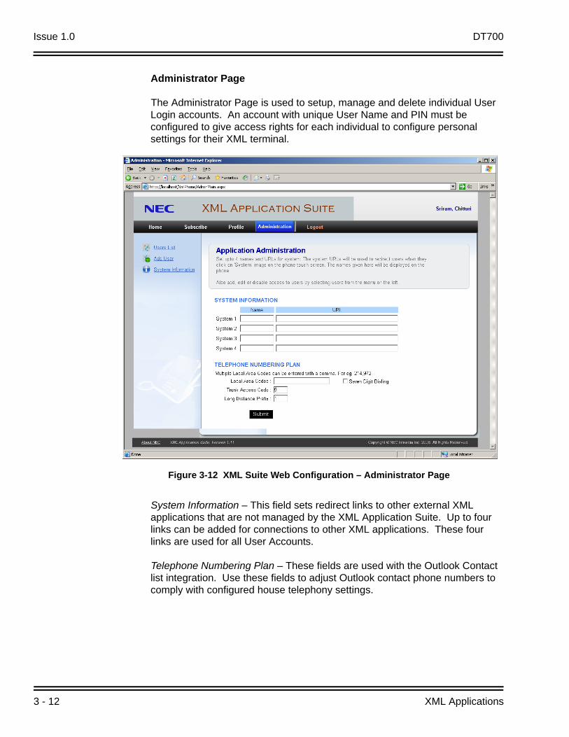
Administrator Page
The Administrator Page is used to setup, manage and delete individual User Login accounts. An account with unique User Name and PIN must be configured to give access rights for each individual to configure personal settings for their XML terminal.
System Information – This field sets redirect links to other external XML applications that are not managed by the XML Application Suite. Up to four links can be added for connections to other XML applications. These four links are used for all User Accounts.
Telephone Numbering Plan – These fields are used with the Outlook Contact list integration. Use these fields to adjust Outlook contact phone numbers to comply with configured house telephony settings.
Figure 3-12 XML Suite Web Configuration – Administrator Page

DT700 Issue 1.0
DT700 Resource Manual 3 - 13
Entering local area codes strips the 1 in front of the area code that might be saved in the Outlook Contact information.
Seven-digit dialing needs to be selected in areas that local calls do not require area codes.
Long Distance Prefix adds a predefined number to Outlook contact information with area codes not listed in the Local Area Codes field.
Trunk Access Code can be used to add a defined number to the front of a saved Outlook number to access an external line.
3. Press Submit to save the settings.

Issue 1.0 DT700
3 - 14 XML Applications
User List
User List can be used to display all active users setup in the system by selecting the Display All Users link in the left column. From the Display All User Link, individual users can be deleted from the XML Application Suite therefore denying access from viewing XML content on an XML terminal and from the XML Application Suite web login.
Figure 3-13 XML Suite Web Configuration – User List

DT700 Issue 1.0
DT700 Resource Manual 3 - 15
Add User
Administrator’s Level access allows an individual (system administrator) to add and configure users for XML Application access. Select the Add User Link in the Left column to add a new user account. A new user account must be setup for each individual that requires access to the XML Application from their DT750 terminal.
Name – For reference enter the First and Last Name of the user to define the account in the appropriate fields.
Login – Enter a unique login name that is used when logging into the user web configuration page. Example: first letter of first name and last name (JDoe).
PIN – PIN is the unique user password used for web configuration and from the terminal XML login home page. Example: use the individual’s extension number.
Email/Contact – these fields are used for administrator reference for the user account.
Figure 3-14 XML Suite Web Configuration – Add User

Issue 1.0 DT700
3 - 16 XML Applications
Is Admin – Select this box if you want to give this user account full administrator rights. Example: Add/Delete users and modify System Link URL information.
These Pages can be set up for Administrator login on any XML terminal.
Home, Subscribe, Profile, and Logout Pages are discussed in the User Login.

DT700 Issue 1.0
DT700 Resource Manual 3 - 17
User Login
1. At the XML Phone Services Login page enter:
Login Name
PIN
2. Press Submit to login to the XML Phone Services.
3. The User Login Home Page has four configuration tabs:Home – navigates from current screen back to the Home Page
Subscribe – Enables XML content to be displayed on the DT750 terminal
Profile – Displays user account information
Logout – Current user logout
These pages can be set up for User Login on their personal XML DT750 terminals.
Figure 3-15 XML Suite Web Configuration – User Login

Issue 1.0 DT700
3 - 18 XML Applications
Home Page
The Home Page is the default entry page.
Figure 3-16 XML Suite Web Configuration – Home Page

DT700 Issue 1.0
DT700 Resource Manual 3 - 19
Subscribe Page
The Subscribe Page has five individual subscription pages that allow or deny content to be viewed from the XLM DT750 terminal.
Alarm Clock
Weather
Stock Market
Photo Album
Outlook
Figure 3-17 XML Suite Web – Subscribe Page

Issue 1.0 DT700
3 - 20 XML Applications
Alarm Clock
To subscribe to the Alarm Clock page:
1. Select the Subscribe button.In the Clock Setting field, select the appropriate Time Zone for your location.
Enable or disable the alarm with the ON/OFF parameter setting.
Use the Date and Time configuration fields to set the desired time and date that the alarm needs to activate.
The Repeat function allows the alarm to repeat on a daily or weekly basis at the set time.
The Note text box, useful to enter reminder text about the alarm purpose, is displayed on the terminal interface.
2. Press Submit to activate the Alarm Setting.
Figure 3-18 XML Suite Web – Alarm Clock

DT700 Issue 1.0
DT700 Resource Manual 3 - 21
Weather
1. Select Subscribe to enable weather content to be displayed on the XML terminal. Each user can select up to three different US ZIP Codes to display the current and the two-day forecast.
2. Press Submit to activate the Weather Service.
The ZIP Codes can be edited also from the XML terminal interface after the service is enabled from the XML Application Suite.
Figure 3-19 XML Suite – Weather

Issue 1.0 DT700
3 - 22 XML Applications
Photo Album
Enable the Photo Album service by selecting Subscribe.
Each user can upload personal pictures or graphics that they want to display on their XML terminal.
1. Assign a name to each uploaded photo by entering text in the name field.
2. Use Browse to search and open the desired graphic content.
3. Press Submit to save the photos to the XML database.
Uploaded photos and graphics are displayed in alphabetical order under Uploaded Files. Run your mouse cursor over the uploaded file image to see how it is displayed on the XML terminal screen.
The XML Application Suite converts size and format for each uploaded file to meet the specifications of the XML terminal display.
Figure 3-20 XML Suite – Photo Album

DT700 Issue 1.0
DT700 Resource Manual 3 - 23
Outlook
The XML Application Suite can integrate with Microsoft Outlook Calendar and Contacts. Enable both or individual Outlook content by selecting the Subscription buttons. To integrate the Outlook calendar and Contact list from your Outlook account, download the Outlook Sync Application from this web page (Click here to install XML Sync Application). The Outlook Sync Application must be installed on the PC of the user that this account is configured for.
XML Application Outlook Sync Application installs an icon in the system tray. Double click this icon to enter the XML Application Suite URL (this is displayed on the Web Configuration screen).
Figure 3-21 XML Suite – Outlook Integration
Figure 3-22 XML Suite – Icon in System Tray

Issue 1.0 DT700
3 - 24 XML Applications
This Sync application runs in the background on the user/personal PC to sync Outlook information from the local Outlook client to the XML Application Network Database.
Microsoft Outlook must be installed and running on the PC where the Outlook Sync Application was downloaded.
Figure 3-23 XML Suite – Sync Application installation

DT700 Issue 1.0
DT700 Resource Manual 3 - 25
1. Enter the Personal Account information Login and PIN that were assigned to the user to login into the XML Application Suite Website.
2. Check Enable Synchronization to sync the XML Outlook Sync tool with your Microsoft Client.
Figure 3-24 XML Suite – Application Outlook Sync
Issue 1.0 DT700
3 - 26 XML Applications
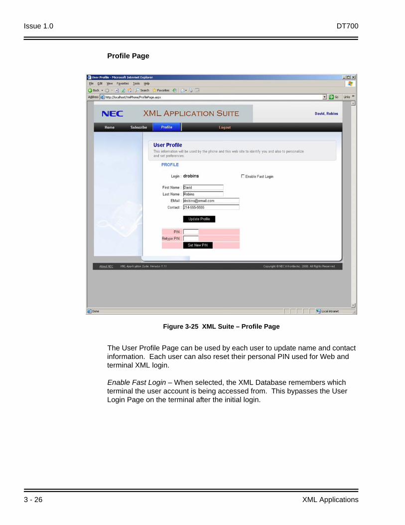
Profile Page
The User Profile Page can be used by each user to update name and contact information. Each user can also reset their personal PIN used for Web and terminal XML login.
Enable Fast Login – When selected, the XML Database remembers which terminal the user account is being accessed from. This bypasses the User Login Page on the terminal after the initial login.
Figure 3-25 XML Suite – Profile Page

DT700 Issue 1.0
DT700 Resource Manual 3 - 27
Logout Page
Figure 3-26 XML Suite – Logout Page

Issue 1.0 DT700
3 - 28 XML Applications
3.2 XML Terminal
To access and view the XML Application on the NEC DT700 XML terminals to criteria need to be met. Terminal configuration needs to have the XML Application URL entered and XML enabled in terminal menu settings.
3.2.1 Terminal Configuration Setup
NEC IP Terminals can be configured in one of three ways:
Manual Handset Programming
IP Manager Application or Auto Configuration Settings
Web Browser** This instruction follows the Web browser Setup procedure. Consult the
corresponding IP terminal user guide if one of the other two methods is desired.
DT700 Issue 1.0
DT700 Resource Manual 3 - 29
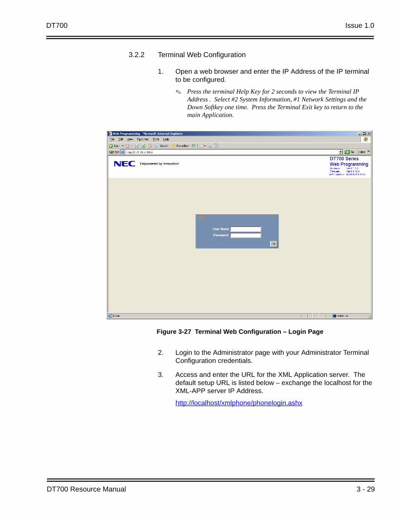
3.2.2 Terminal Web Configuration
1. Open a web browser and enter the IP Address of the IP terminal to be configured.
Press the terminal Help Key for 2 seconds to view the Terminal IP Address . Select #2 System Information, #1 Network Settings and the Down Softkey one time. Press the Terminal Exit key to return to the main Application.
2. Login to the Administrator page with your Administrator Terminal Configuration credentials.
3. Access and enter the URL for the XML Application server. The default setup URL is listed below – exchange the localhost for the XML-APP server IP Address.
http://localhost/xmlphone/phonelogin.ashx
Figure 3-27 Terminal Web Configuration – Login Page

Issue 1.0 DT700
3 - 30 XML Applications
4. Select OK and Save – the terminal reboots with the new settings.
Figure 3-28 Terminal Web Configuration – Assign Home URL

DT700 Issue 1.0
DT700 Resource Manual 3 - 31
3.2.3 Enable XML Application on the XML Terminal
1. Press the Menu key.
2. Select #3 or touch the Tool icon.
3. Select #1 or touch the Service text.
4. The display prompts you for the PIN that was set up for your individual account. Enter your personal PIN using the terminal dial pad and press the Login softkey.
Figure 3-29 Enable XML Application on Terminal
Figure 3-30 Enable XML Application – Enter PIN
MenuKey

Issue 1.0 DT700
3 - 32 XML Applications
3.2.4 Terminal Display Screens
1. Home Screen – Use the Home Screen to navigate to other Subscribed applications. Touch the associated Icon to navigate away to this page. Each linked page has a Home icon in the upper right corner that redirects you back to this Home Screen.
2. System Screen – System Screen is set up by the administrator as a link to other XML applications not associated with this application. Up to four other links can be supported on the gateway page.
Figure 3-31 Terminal Display Screen – Home
Figure 3-32 Terminal Display Screen – System

DT700 Issue 1.0
DT700 Resource Manual 3 - 33
3. Clock and Calendar – Use the clock and calendar screen to see the current time and date, and view days on the calendar.
Touch the Calendar arrows to view the previous and next month.
Touch the System Icon to redirect you to the System Screen.
Touch the Home icon to go back to the Home Screen.
Figure 3-33 Terminal Display Screen – Clock & Calendar

Issue 1.0 DT700
3 - 34 XML Applications
4. Alarm Screen – From the Web Configuration Utility, day and time are set for a reminder displayed on your terminal screen. The screen displays current time and date as well as the reminder time and date, plus notes about the reminder that were entered through the Web Configuration Utility.
Touch the System Icon to go back to the System Screen.
Touch the Home icon to go back to the Home Screen.
Figure 3-34 Terminal Display Screen – Alarm

DT700 Issue 1.0
DT700 Resource Manual 3 - 35
5. Weather – The weather screen displays zip code, city name, current temperature, and 3-day forecast. Up to three ZIP Codes in the continental US can be entered.
Touch the Weather Icon to refresh the current page. (Page auto-refreshes every minute).
Touch the Edit Zip Codes to add or remove ZIP Codes from the terminal interface.
Touch the Home Icon to return to the Home Page.
Figure 3-35 Terminal Display Screen – Weather Display
Figure 3-36 Terminal Display Screen – Weather Zip Code Assignment

Issue 1.0 DT700
3 - 36 XML Applications
6. Photo Album – The Photo Album displays the previously uploaded pages for each individual account in the Web Configuration utility. These photos automatically refresh to the next uploaded photo according to the time set in the Web Configuration Utility.
Touch the Home Icon on the Terminal Screen anytime to return to the Home Screen.
Figure 3-37 Terminal Display Screen – Photo Album Display

DT700 Resource Manual 4 - 1
Do
wn
loa
d R
ing
Ton
es a
nd
MO
H
4Download Ring Tones and MOH
SECTION 1 RING TONE SPECIFICATIONS
Choose an audio clip from the Web or a CD and use audio editing software to convert the audio sample to the specifications listed next.
1.1 Ring Tone – Format Specifications
File format – .wav
Bit Rate – 64K
Audio sample size – 8 bit
Channel – Mono
Audio sample rate – 8kHz/16
Audio format – CCITT u-law
File size – 256KB or under

Issue 1.0 DT700
4 - 2 Download Ring Tones and MOH
1.2 Ring Tone Upload Procedure
1. Save the converted ring tone (format shown above) into a local directory on the PC.
2. Start TFTP/FTP on the PC.
Figure 4-1 Ring Tone Upload – Save to Local Directory
Figure 4-2 Ring Tone Upload – Start TFTP/FTP on PC

DT700 Issue 1.0
DT700 Resource Manual 4 - 3
3. Point TFTP/FTP to the saved Ring Tone file.
Figure 4-3 Ring Tone Upload – Point TFTP/FTP to Ring Tone File

Issue 1.0 DT700
4 - 4 Download Ring Tones and MOH
4. Terminal WebLogin or Menu Button
a. Setting
b. Download
c. Protocol (TFTP/FTP)
d. Download Address (IP of TFPT/FTP)
e. Download Files
f. Ring Tone (Download Tone 1, 2, 3)
g. Enter Name of file, then Execute
Figure 4-4 Ring Tone Upload – Enter File Name

DT700 Issue 1.0
DT700 Resource Manual 4 - 5
1.3 Terminal Ring Tone Setting
1. Terminal Weblogin or Menu Button
a. Setting
b. User Setting
c. Incoming Call
d. Ring Tone
e. Internal Call
f. Download (select Download 1, 2, or 3)
If the download fails, verify the file type, format size and address are correct.
Figure 4-5 Ring Tone Terminal Settings

Issue 1.0 DT700
4 - 6 Download Ring Tones and MOH
SECTION 2 MUSIC ON HOLD (MOH) TONE FORMAT
File format – .wav
Audio format – CCITT u-law
Audio sample rate – 8kHz
Audio sample size – 8 bit
Audio Channel – Mono
File size – 256KB or under
2.1 MOH Upload Procedure
1. Save the converted MOH Tone (in the format above) into a local directory on the PC.
Figure 4-6 Music on Hold – Save to Local Directory on PC

DT700 Issue 1.0
DT700 Resource Manual 4 - 7
2. Start TFTP/FTP on the PC.
3. Point TFTP/FTP to the saved MOH Tone file.
Figure 4-7 Music on Hold – Start TFTP/FTP on PC
Figure 4-8 Music on Hold – Point TFTP/FTP to Ring Tone File
Issue 1.0 DT700
4 - 8 Download Ring Tones and MOH
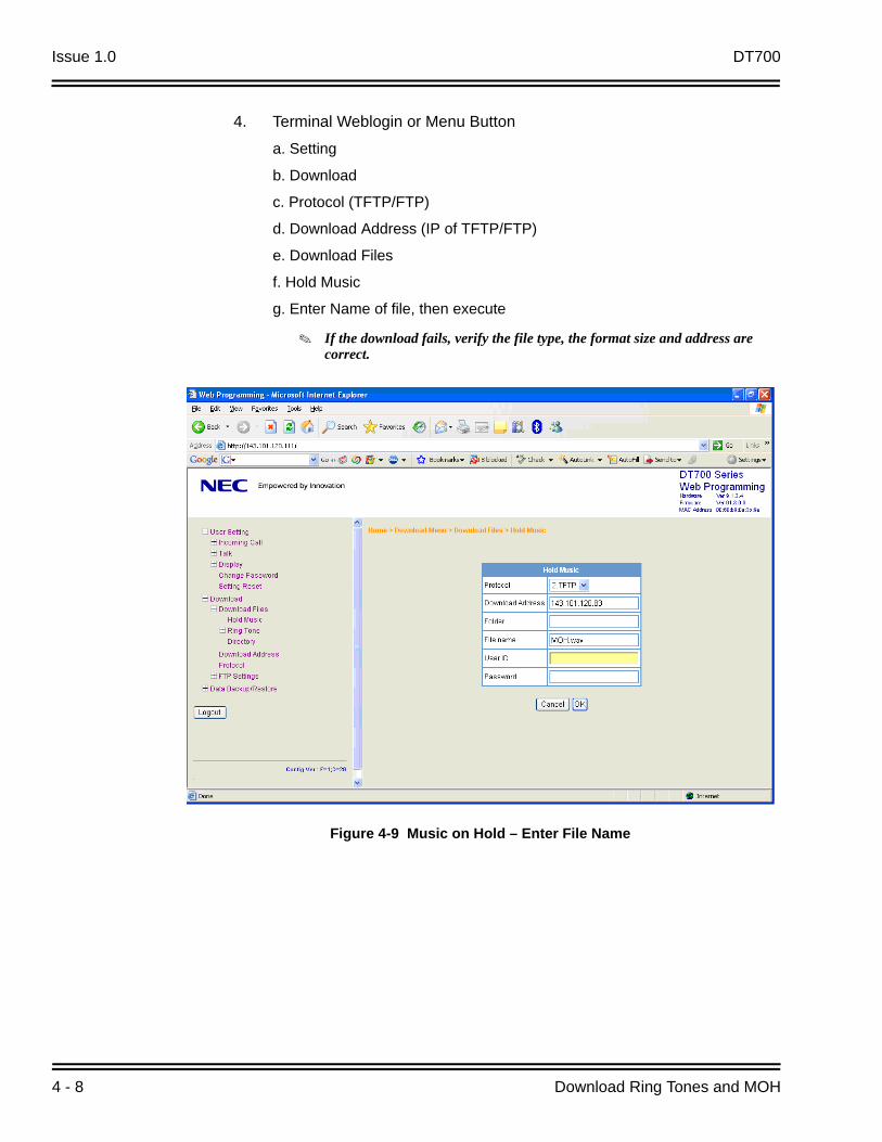
4. Terminal Weblogin or Menu Button
a. Setting
b. Download
c. Protocol (TFTP/FTP)
d. Download Address (IP of TFTP/FTP)
e. Download Files
f. Hold Music
g. Enter Name of file, then execute
If the download fails, verify the file type, the format size and address are correct.
Figure 4-9 Music on Hold – Enter File Name

DT700 Issue 1.0
DT700 Resource Manual 4 - 9
2.2 Terminal MOH Setting
1. Terminal Weblogin or Menu Button
a. Setting
b. User Setting
c. Talk
d. Hold Music
e. Download
You can use the Windows Player to convert audio formats.
Figure 4-10 Music on Hold – Download

Issue 1.0 DT700
4 - 10 Download Ring Tones and MOH
2. Start ➜ Programs ➜ Accessories ➜ Entertainment ➜ Sound Recorder.
3. File ➜ Open (choose the wave saved .wav file).
4. File ➜ Properties ➜ Convert Now (Select Format and Attributes).
Sound editing software may be required to edit the file size if too large, or if the audio levels in playback are distorted after file conversion.
Figure 4-11 Sound Recorder – Start Program
Figure 4-12 Sound Recorder – Sound Selection

DT700 Resource Manual 5 - 1
DT
Arch
iver
5DT Archiver
SECTION 1 DT ARCHIVER INTRODUCTION
The DT Archiver allows file compression and decompression of the DT700 Series Terminals. The DT Archiver has two screens:
Compressed File Creating Screen
The Decompress File Screen
1.1 Creating Compressed Files
A compressed file can be created by specifying an optional folder on the compressed file creating screen.
1. The Compress tab displays the file compress screen.
2. Press Browse to search for an existing file to compress.
3. Input the path of the known file to compress.
4. Press Browse to search for a destination folder to place the compressed file.
5. The output path can be input manually.
Figure 5-1 DT Archiver – Compress Files
1
23
45
6

Issue 1.0 DT700
5 - 2 DT Archiver
6. Press Compress to execute the file compression process.
All files in chosen folders and subfolders are selected for compression.
If 256 files or more are selected, compression does not take place and an error message is displayed.
1.2 Decompressing Files
Use the Decompress tab to select the Decompress screen.
1. The Decompress tab displays the file decompress screen.
2. Press Browse to search for an existing file to decompress.
3. Input the path of the known file to decompress.
4. Press Browse to search for a destination folder to place the decompressed file.
5. The output path can be input manually.
6. Press Decompress to execute the file decompression process.
Figure 5-2 DT Archiver – Decompress Files
1
23
4
5
6

Resource Manual
NEC Unified Solutions, Inc.
Issue 1.0
DT700


