Directional control valvesNG6...NG32
D03...D10
6
DIRECTIONAL CONTROL VALVES 1
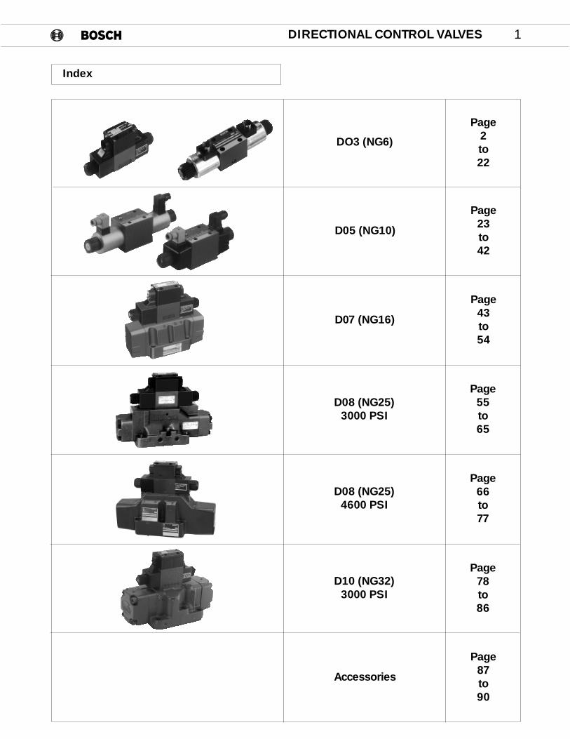
Index
DO3 (NG6)
D05 (NG10)
D07 (NG16)
D08 (NG25)3000 PSI
D08 (NG25)4600 PSI
Accessories
Page2to22
Page23to42
Page43to54
Page55to65
Page66to77
Page87to90
D10 (NG32)3000 PSI
Page78to86
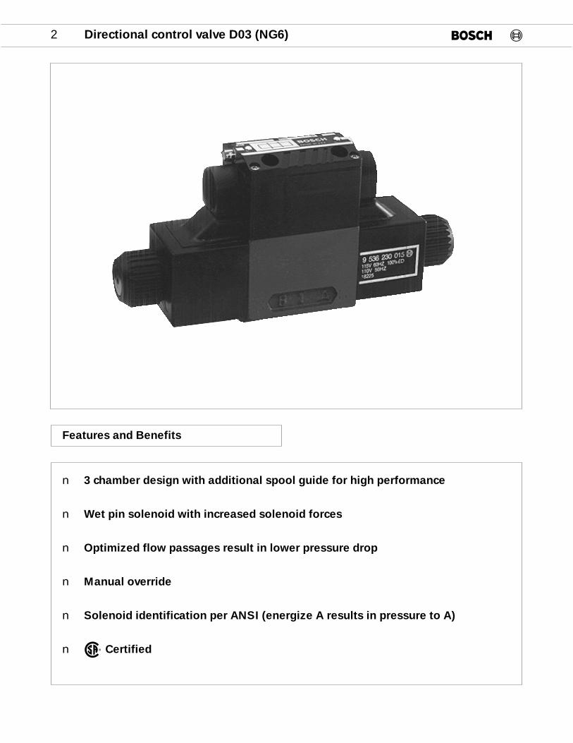
2 Directional control valve D03 (NG6)
Features and Benefits
n 3 chamber design with additional spool guide for high performance
n Wet pin solenoid with increased solenoid forces
n Optimized flow passages result in lower pressure drop
n Manual override
n Solenoid identification per ANSI (energize A results in pressure to A)
n Certified®
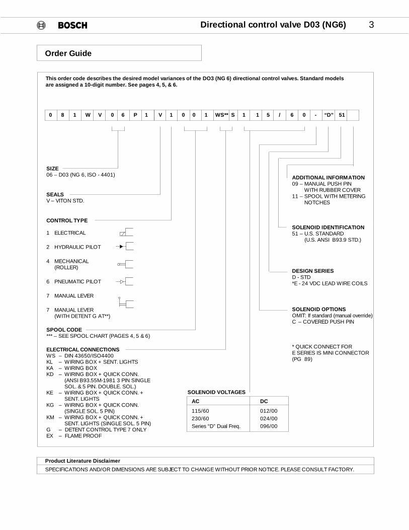
Directional control valve D03 (NG6) 3
This order code describes the desired model variances of the DO3 (NG 6) directional control valves. Standard models are assigned a 10-digit number. See pages 4, 5, & 6.
SIZE06 – D03 (NG 6, ISO - 4401)
SEALSV – VITON STD.
CONTROL TYPE
1 ELECTRICAL
2 HYDRAULIC PILOT
4 MECHANICAL(ROLLER)
6 PNEUMATIC PILOT
7 MANUAL LEVER
7 MANUAL LEVER(WITH DETENT G AT**)
SPOOL CODE*** – SEE SPOOL CHART (PAGES 4, 5 & 6)
ELECTRICAL CONNECTIONSWS – DIN 43650/ISO4400KL – WIRING BOX + SENT. LIGHTSKA – WIRING BOXKD – WIRING BOX + QUICK CONN.
(ANSI B93.55M-1981 3 PIN SINGLE SOL. & 5 PIN. DOUBLE. SOL.)
KE – WIRING BOX + QUICK CONN. + SENT. LIGHTS
KG – WIRING BOX + QUICK CONN. (SINGLE SOL. 5 PIN)
KM – WIRING BOX + QUICK CONN. + SENT. LIGHTS (SINGLE SOL. 5 PIN)
G – DETENT CONTROL TYPE 7 ONLYEX – FLAME PROOF
0 8 1 W V 0 6 P 1 V 1 0 0 1 WS** S 1 1 5 / 6 0 - “D” 51
SOLENOID VOLTAGES
AC DC
115/60 012/00230/60 024/00Series “D” Dual Freq. 096/00
ADDITIONAL INFORMATION09 – MANUAL PUSH PIN
WITH RUBBER COVER11 – SPOOL WITH METERING
NOTCHES
SOLENOID IDENTIFICATION51 – U.S. STANDARD
(U.S. ANSI B93.9 STD.)
DESIGN SERIESD - STD*E - 24 VDC LEAD WIRE COILS
SOLENOID OPTIONSOMIT: If standard (manual override) C – COVERED PUSH PIN
* QUICK CONNECT FORE SERIES IS MINI CONNECTOR(PG 89)
Order Guide
Product Literature Disclaimer
SPECIFICATIONS AND/OR DIMENSIONS ARE SUBJECT TO CHANGE WITHOUT PRIOR NOTICE. PLEASE CONSULT FACTORY.
KA KD KE KG KL KM WS WS
SPOOL SYMBOLS TRANSITION 110/115 110/115 110/115 110/115 110/115 110/115 110/115 12 VDC.NO. 220/230 220/230 220/230 220/230 220/230 220/230 220/230 24 VDC.
024/00 024/00 024/00 024/00 96 VDC.
Z069 Z201 Z267 Z135 Z003 Z397000 Z102 Z234 Z300 Z168 Z036 Z430
Z484
Z070 Z202 Z268 Z136 Z004 Z398001 Z103 Z235 Z301 Z169 Z037 Z431
Z511 Z477
Z463 Z512001* Z521
Z071 Z203 Z269 Z137 Z005 Z399002 Z104 Z236 Z302 Z170 Z038 Z432
Z531 Z492
Z464002*
Z072 Z204 Z270 Z138 Z006 Z400004 Z105 Z237 Z303 Z171 Z039 Z433
Z497 Z478 Z516
Z465004*
Z073 Z205 Z271 Z139 Z007 Z401005 Z106 Z238 Z304 Z172 Z040 Z434
Z074 Z206 Z272 Z140 Z008 Z402006 Z107 Z239 Z305 Z173 Z041 Z435
Z075 Z207 Z273 Z333 Z141 Z365 Z009 Z403010 Z108 Z240 Z306 Z349 Z174 Z381 Z042 Z436
Z508 Z491
Z076 Z208 Z274 Z334 Z142 Z366 Z010 Z404011* Z109 Z241 Z307 Z350 Z175 Z382 Z043 Z437
Z487
Z077 Z209 Z275 Z335 Z143 Z367 Z011 Z405012 Z110 Z242 Z308 Z351 Z176 Z383 Z044 Z438
Z480
Z078 Z210 Z276 Z336 Z144 Z368 Z012 Z406014 Z111 Z243 Z309 Z352 Z177 Z384 Z045 Z439
Z079 Z211 Z277 Z337 Z145 Z369 Z013 Z407016 Z112 Z244 Z310 Z353 Z178 Z385 Z046 Z440
Z467016*
4 Directional control valve D03 (NG6)
P T
A B
P T
A B
P T
A B
P T
A B
P T
A B
P T
A B
P T
A B
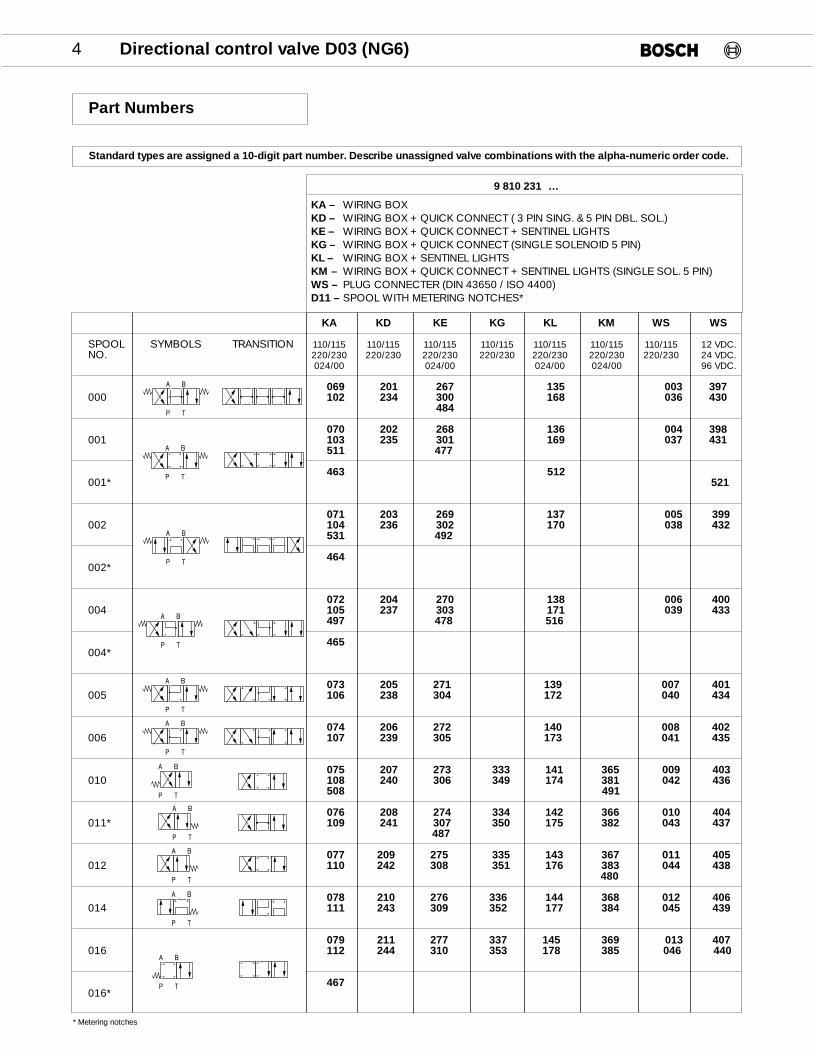
Standard types are assigned a 10-digit part number. Describe unassigned valve combinations with the alpha-numeric order code.
9 810 231Z…
KA – WIRING BOXKD – WIRING BOX + QUICK CONNECT ( 3 PIN SING. & 5 PIN DBL. SOL.)KE – WIRING BOX + QUICK CONNECT + SENTINEL LIGHTSKG – WIRING BOX + QUICK CONNECT (SINGLE SOLENOID 5 PIN)KL – WIRING BOX + SENTINEL LIGHTSKM – WIRING BOX + QUICK CONNECT + SENTINEL LIGHTS (SINGLE SOL. 5 PIN)WS – PLUG CONNECTER (DIN 43650 / ISO 4400)D11 – SPOOL WITH METERING NOTCHES*
* Metering notches
Part Numbers
P T
A B
P T
A B
P T
A B
P T
A B

KA KD KE KG KL KM WS WS
SPOOL SYMBOLS TRANSITION 110/115 110/115 110/115 110/115 110/115 110/115 110/115 12 VDC.NO. 220/230 220/230 220/230 220/230 220/230 220/230 220/230 24 VDC.
024/00 024/00 96 VDC.
Z080 Z212 Z278 Z146 Z014 Z408018 Z113 Z245 Z311 Z179 Z047 Z441
Z479 Z517
Z468018*
Z081 Z213 Z279 Z147 Z015 Z409020 Z114 Z246 Z312 Z180 Z048 Z442
Z481 Z518
Z082 Z214 Z280 Z338 Z148 Z370 Z016 Z410024 Z115 Z247 Z313 Z354 Z181 Z386 Z049 Z443
Z525 Z525
Z083 Z215 Z281 Z149 Z017 Z411026 Z116 Z248 Z314 Z182 Z050 Z444
Z084 Z216 Z282 Z339 Z150 Z371 Z018 Z412027 Z117 Z249 Z315 Z355 Z183 Z387 Z051 Z445
Z474 Z475 Z496028
Z085 Z217 Z283 Z340 Z151 Z372 Z019 Z413031 Z118 Z250 Z316 Z356 Z184 Z388 Z052 Z446
Z086 Z218 Z284 Z341 Z152 Z373 Z020 Z414032 Z119 Z251 Z317 Z357 Z185 Z389 Z053 Z447
Z087 Z219 Z285 Z342 Z153 Z374 Z021 Z415033 Z120 Z252 Z318 Z358 Z186 Z390 Z054 Z448
Z488
Z546 Z534036 Z493
Z088 Z220 Z286 Z154 Z022 Z416040 Z121 Z253 Z319 Z187 Z055 Z449
Z089 Z221 Z287 Z155 Z023 Z417041 Z122 Z254 Z320 Z188 Z056 Z450
Z090 Z222 Z288 Z156 Z024 Z418042 Z123 Z255 Z321 Z189 Z057 Z451
Z091 Z223 Z289 Z343 Z157 Z375 Z025 Z419045 Z124 Z256 Z322 Z359 Z190 Z391 Z058 Z452
Z092 Z224 Z290 Z158 Z026 Z420062 Z125 Z257 Z323 Z191 Z059 Z453
Z093 Z225 Z291 Z344 Z159 Z376 Z027 Z421068 Z126 Z258 Z324 Z360 Z192 Z392 Z060 Z454
Z094 Z226 Z292 Z345 Z160 Z377 Z028 Z422070 Z127 Z259 Z325 Z361 Z193 Z393 Z061 Z455
Z095 Z227 Z293 Z346 Z161 Z378 Z029 Z423074 Z128 Z260 Z326 Z362 Z194 Z394 Z062 Z456
Z096 Z228 Z294 Z162 Z030 Z424087 Z129 Z261 Z327 Z195 Z063 Z457
Z097 Z229 Z295 Z347 Z163 Z379 Z031 Z425088 Z130 Z262 Z328 Z363 Z196 Z395 Z064 Z458
Directional control valve D03 (NG6) 5
P T
A B
P T
A B
P T
A B
P T
A B
P T
A B
P T
A B
P T
A B
P T
A B
P T
A B
P T
A B
P T
A B
P T
A B
P T
A B
P T
A B
P T
A B
P T
A B
* Metering notches
P T
A B
P T
A B
SPOOLSYMBOLS TRANSITIONNO.
Z365 Z526000 Z379
*Z372
Z366 Z381001 Z380
*Z373
Z367 Z383002 Z382
*Z374
Z368 Z385004 Z384
*Z375
Z387010 Z541 Z333 Z386
*Z544
Z358 Z334 Z369 Z389012 Z388
*Z361 *Z376
Z370014
016 Z335
Z390018 –
*Z378020 Z359
Z371
–027 Z391
KA KD KE KG KL KM WS WS
SPOOL SYMBOLS TRANSITION 110/115 110/115 110/115 110/115 110/115 110/115 110/115 12 VDC.NO. 220/230 220/230 220/230 220/230 220/230 220/230 220/230 24 VDC.
96 VDC.
Z472 Z473 Z519089 Z489
Z098 Z230 Z296 Z164 Z032 Z426091 Z131 Z263 Z329 Z197 Z065 Z459
Z099 Z231 Z297 Z165 Z033 Z427095 Z132 Z264 Z330 Z198 Z066 Z460
Z100 Z232 Z298 Z348 Z166 Z380 Z034 Z428923 Z133 Z265 Z331 Z364 Z199 Z396 Z067 Z461
6 Directional control valve D03 (NG6)
2 4 6 7
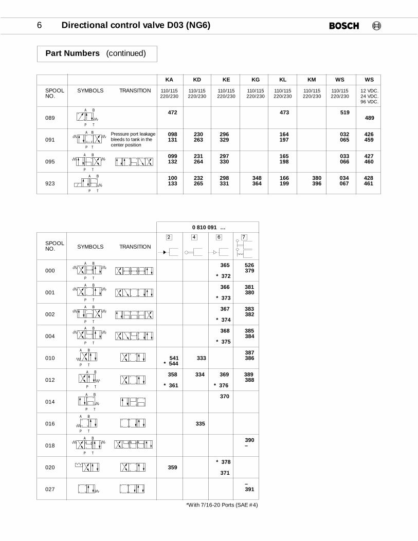
0 810 091Z…
P T
A B
P T
A B
P T
A B
P T
A B
P T
A B
P T
A B
P T
A B
P T
A B
P T
A B
Part Numbers (continued)
Pressure port leakagebleeds to tank in thecenter positionP T
A B
P T
A B
P T
A B
P T
A B
*With 7/16-20 Ports (SAE #4)
Directional control valve D03 (NG6) 7
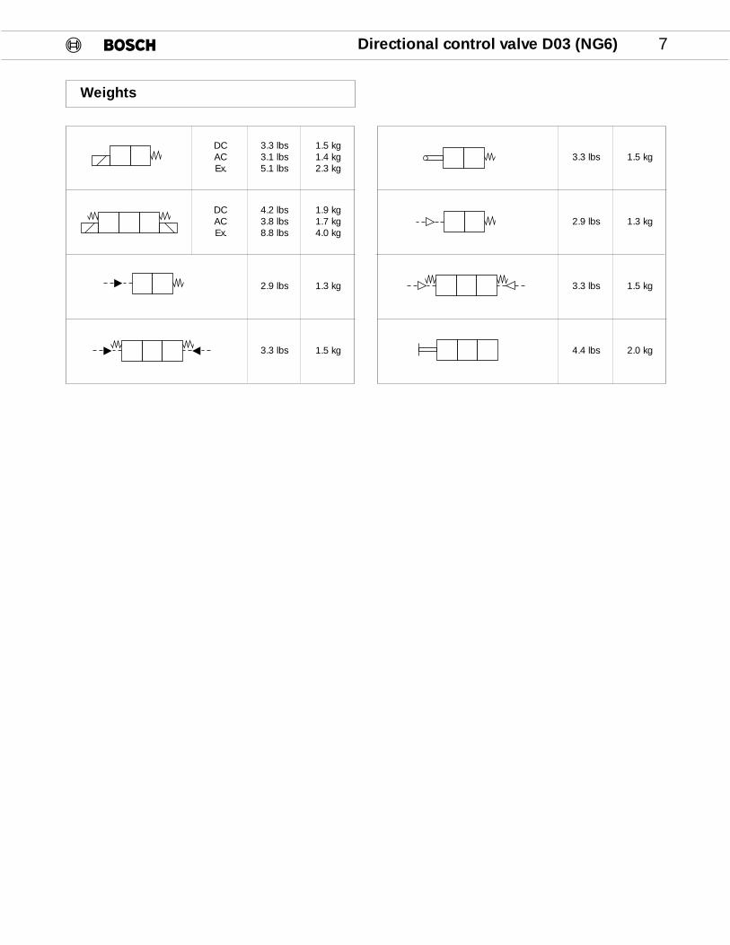
Weights
DCACEx.
3.3 lbs3.1 lbs5.1 lbs
1.5 kg1.4 kg2.3 kg
DCACEx.
4.2 lbs3.8 lbs8.8 lbs
1.9 kg1.7 kg4.0 kg
1.3 kg2.9 lbs
1.5 kg3.3 lbs
3.3 lbs 1.5 kg
2.9 lbs 1.3 kg
3.3 lbs 1.5 kg
4.4 lbs 2.0 kg
8 Directional control valve D03 (NG6)
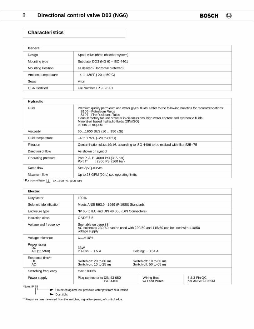
Electric
Duty factor 100%
Solenoid identification Meets ANSI B93.9 - 1969 (R 1988) Standards
Enclosure type *IP 65 to IEC and DIN 40 050 (DIN Connectors)
Insulation class C VDE § 5
Voltage and frequency See table on page 88AC-solenoids 230/60 can be used with 220/50 and 115/60 can be used with 110/50 voltage supply
Voltage tolerance UNOM±10%
Power ratingDC 33WAC (115/60) In Rush: ~ 1.5 A Holding: ~ 0.54 A
Response time**DC Switch-on: 20 to 60 ms Switch-off: 10 to 60 msAC Switch-on: 10 to 25 ms Switch-off: 50 to 65 ms
Switching frequency max. 1800/h
Power supply Plug connector to DIN 43 650 Wiring Box 5 & 3 Pin QCISO 4400 w/ Lead Wires per ANSI B93.55M
Hydraulic
Fluid Premium quality petroleum and water glycol fluids. Refer to the following bulletins for recommendations:S106 - Petroleum FluidsS107 - Fire Resistant Fluids
Consult factory for use of water in oil emulsions, high water content and synthentic fluids.Mineral-oil based hydraulic-fluids (DIN/ISO) others on request
Viscosity 60…1600 SUS (10 …350 cSt)
Fluid temperature –4 to 175°F (–20 to 80°C)
Filtration Contamination class 19/16, according to ISO 4406 to be realized with filter ß25=75
Direction of flow As shown on symbol
Operating pressure Port P, A, B: 4600 PSI (315 bar)Port T* : 2300 PSI (160 bar)
Rated flow See ∆p/Q-curves
Maximum flow Up to 23 GPM (90 L) see operating limits
General
Design Spool valve (three chamber system)
Mounting type Subplate, DO3 (NG 6) – ISO 4401
Mounting Position as desired (Horizontal preferred)
Ambient temperature –4 to 120°F (-20 to 50°C)
Seals Viton
CSA Certified File Number LR 93267-1
*Note: IP 65
1
Protected against low pressure water jets from all direction
Dust tight
Characteristics
* For control type EX 1500 PSI (100 bar)
** Response time measured from the switching signal to opening of control edge.
Directional control valve D03 (NG6) 9
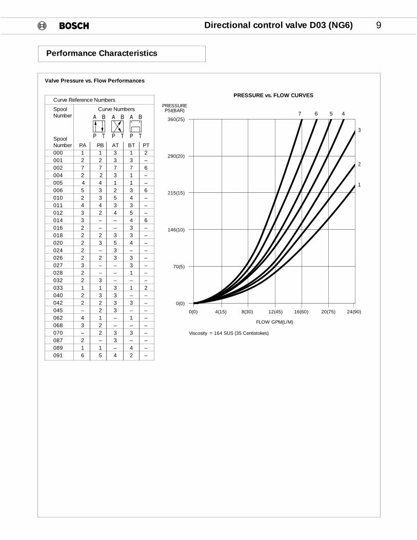
Valve Pressure vs. Flow Performances
Curve Reference Numbers
Spool Curve NumbersNumber
SpoolNumber PA PB AT BT PT000 1 1 3 1 2001 2 2 3 3 –002 7 7 7 7 6004 2 2 3 1 –005 4 4 1 1 –006 5 3 2 3 6010 2 3 5 4 –011 4 4 3 3 –012 3 2 4 5 –014 3 – – 4 6016 2 – – 3 –018 2 2 3 3 –020 2 3 5 4 –024 2 – 3 – –026 2 2 3 3 –027 3 – – 3 –028 2 – – 1 –032 2 3 – – –033 1 1 3 1 2040 2 3 3 – –042 2 2 3 3 –045 – 2 3 – –062 4 1 – 1 –068 3 2 – – –070 – 2 3 3 –087 2 – 3 – –089 1 1 – 4 –091 6 5 4 2 –
360(25)
290(20)
215(15)
146(10)
70(5)
0(0)
0(0) 4(15) 8(30) 12(45) 16(60) 20(75) 24(90)
FLOW GPM(L/M)
PRESSUREPSI(BAR)
PRESSURE vs. FLOW CURVES
3
2
1
Performance Characteristics
A B
P T
A B
P T
A B
P T
7 6 5 4
Viscosity = 164 SUS (35 Centistokes)

MALFUNCTION CURVES
10 Directional control valve D03 (NG6)
Performance Characteristics
Operating limits
The curves refer to applications with symmetrical flow.In the case of asymmetric flow (e.g. one port not used) reduced values may result.
SpoolNumber
001002004010012018020045068
(A)
123111114
(B)
121111113
Curve Numbers
Curve Reference Numbers
SERIES E
DC Solenoids
3600(250)
2900(200)
2200(150)
1450(100)
700(50)
00 3 (10) 5 (20) 8 (30) 10 (40) 13 (50)
Flow GPM (L/min)
A Switch-on
4 2 3
1
PRESSUREPSI (BAR)
3600(250)
2900(200)
2200(150)
1450(100)
700(50)
00 3 (10) 5 (20) 8 (30) 10 (40) 13 (50)
Flow GPM (L/min)
B Switch-off
2
3
1
PRESSUREPSI (BAR)
Directional control valve D03 (NG6) 11
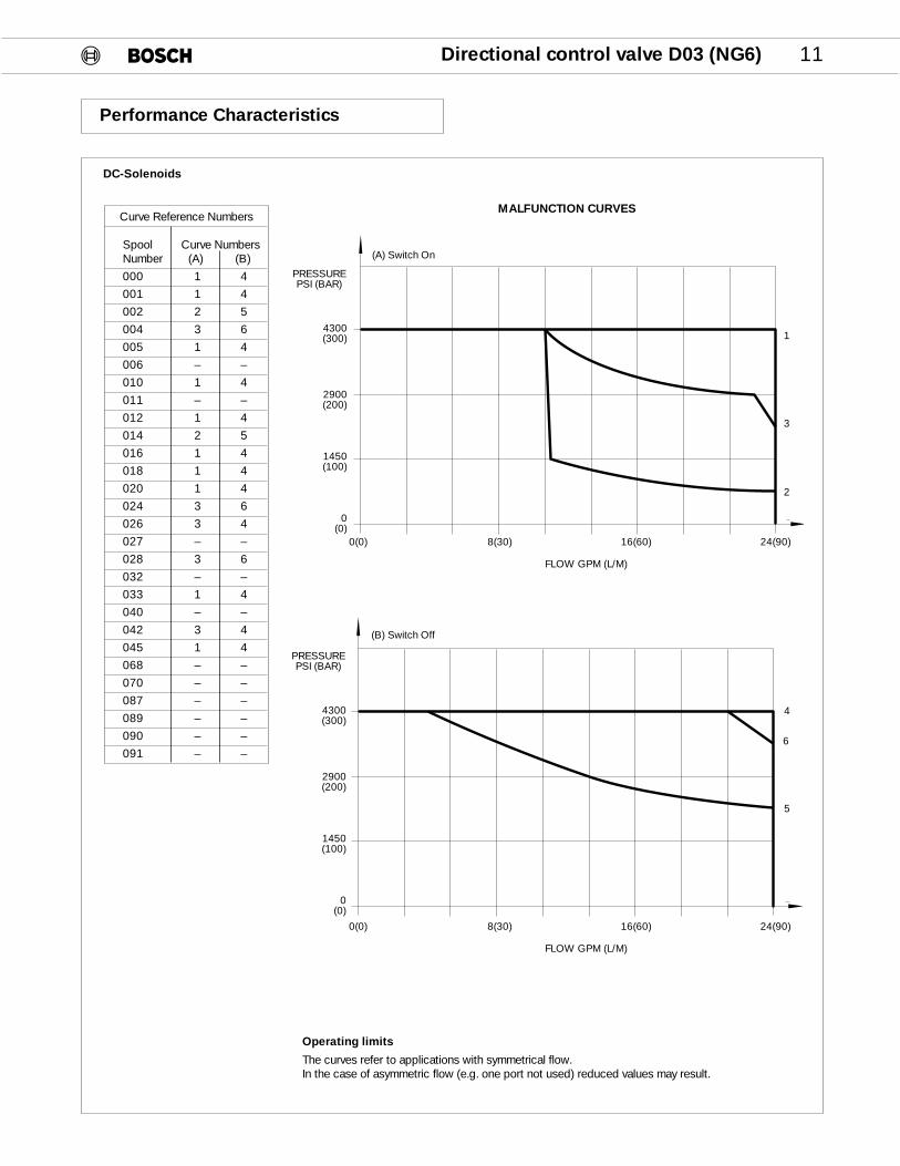
Operating limits
The curves refer to applications with symmetrical flow.In the case of asymmetric flow (e.g. one port not used) reduced values may result.
DC-Solenoids
4300(300)
2900(200)
1450(100)
0(0)
1
2
3
4
5
6
Curve Reference Numbers
Spool Curve NumbersNumber (A) (B)
000 1 4
001 1 4
002 2 5
004 3 6
005 1 4
006 – –
010 1 4
011 – –
012 1 4
014 2 5
016 1 4
018 1 4
020 1 4
024 3 6
026 3 4
027 – –
028 3 6
032 – –
033 1 4
040 – –
042 3 4
045 1 4
068 – –
070 – –
087 – –
089 – –
090 – –
091 – –
0(0) 8(30) 16(60) 24(90)
FLOW GPM (L/M)
PRESSUREPSI (BAR)
MALFUNCTION CURVES
Performance Characteristics
4300(300)
2900(200)
1450(100)
0(0)
PRESSUREPSI (BAR)
(A) Switch On
(B) Switch Off
0(0) 8(30) 16(60) 24(90)
FLOW GPM (L/M)
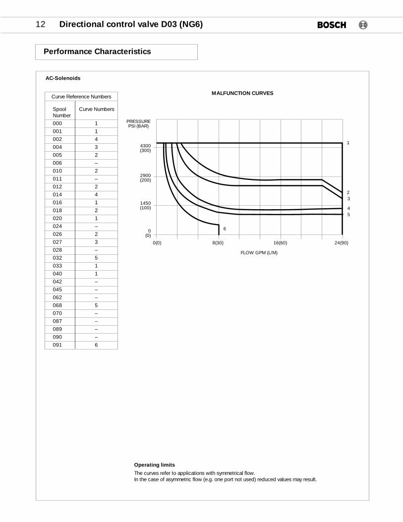
12 Directional control valve D03 (NG6)
Curve Reference Numbers
Spool Curve NumbersNumber
000 1
001 1
002 4
004 3
005 2
006 –
010 2
011 –
012 2
014 4
016 1
018 2
020 1
024 –
026 2
027 3
028 –
032 5
033 1
040 1
042 –
045 –
062 –
068 5
070 –
087 –
089 –
090 –
091 6
Operating limits
The curves refer to applications with symmetrical flow.In the case of asymmetric flow (e.g. one port not used) reduced values may result.
AC-Solenoids
Performance Characteristics
1
23
45
6
0(0) 8(30) 16(60) 24(90)
FLOW GPM (L/M)
4300(300)
2900(200)
1450(100)
0(0)
PRESSUREPSI (BAR)
MALFUNCTION CURVES
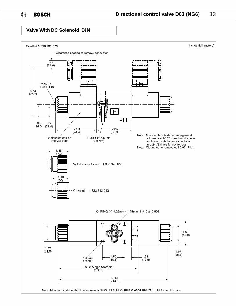
Directional control valve D03 (NG6) 13
P
2.56(65.0)
2.93(74.4)
3.73(94.7)
.87(22.0)
.94(24.0)
MANUALPUSH PIN
TORQUE 5.0 lbft(7.0 Nm)
‘O’ RING (4) 9.25mm x 1.78mm 1 810 210 803
1.81(46.0)
1.28(32.5)
1.22(31.0)
1.59(40.5)
.53(13.5)
4 x ø.21(4 x ø5.3)
5.93 Single Solenoid(150.6)
8.43(214.1)
Note: Mounting surface should comply with NFPA T3.5 IM RI-1984 & ANSI B93.7M - 1986 specifications.
Note: Min. depth of fastener engagement is based on 1-1/2 times bolt diameter for ferrous subplates or manifolds and 2-1/2 times for nonferrous.Note: Clearance to remove coil 2.93 (74.4)
Clearance needed to remove connector
.47(12.0)
A
P
B
T
Solenoids can berotated ±90°
1.46(37.2)
.1.18(30)
With Rubber Cover 1 833 343 015
Covered 1 833 343 013
Valve With DC Solenoid DIN
Inches (Millimeters)Seal Kit 9 810 231 529

14 Directional control valve D03 (NG6)
Valve With AC Solenoid DIN
P
2.56(65.0)
2.63(66.9)
3.70(94.0)
.87(22.0)
.94(24.0)
MANUALPUSH PIN
TORQUE 5.0 lbft(7.0 Nm)
‘O’ RING (4) 9.25mm x 1.78mm 1 810 210 803
1.81(46.0)
1.28(32.5)
1.22(31.0)
1.59(40.5)
.53(13.5)
4 x ø.21(4 x ø5.3)
5.63 Single Solenoid(143.1)
7.82(198.7)
.47(12.0)
Clearance needed to remove connector
A
P
B
T
1.46(37.2)
.1.18(30)
With Rubber Cover 1 833 343 015
Covered 1 833 343 013
Solenoids can berotated ±90°
Note: Mounting surface should comply with NFPA T3.5 IM RI-1984 & ANSI B93.7M - 1986 specifications.
Note: Min. depth of fastener engagement is based on 1-1/2 times bolt diameter for ferrous subplates or manifolds and 2-1/2 times for nonferrous.Note: Clearance to remove coil 2.63 (66.9)
Inches (Millimeters)Seal Kit 9 810 231 529
Directional control valve D03 (NG6) 15
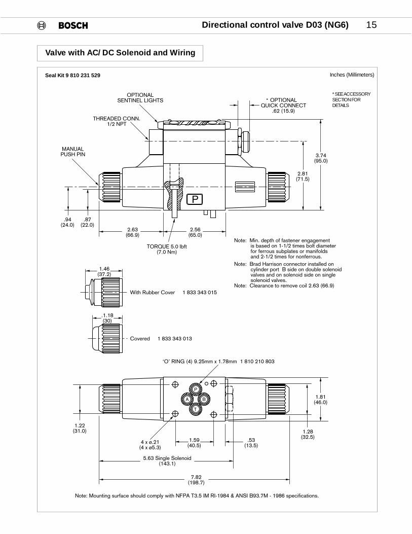
Valve with AC/DC Solenoid and Wiring
P
2.56(65.0)
2.63(66.9)
2.81(71.5)
3.74(95.0)
.87(22.0)
.94(24.0)
MANUALPUSH PIN
THREADED CONN.1/2 NPT
OPTIONALSENTINEL LIGHTS
TORQUE 5.0 lbft(7.0 Nm)
‘O’ RING (4) 9.25mm x 1.78mm 1 810 210 803
1.81(46.0)
1.28(32.5)
1.22(31.0)
1.59(40.5)
.53(13.5)
4 x ø.21(4 x ø5.3)
5.63 Single Solenoid(143.1)
7.82(198.7)
Note: Mounting surface should comply with NFPA T3.5 IM RI-1984 & ANSI B93.7M - 1986 specifications.
Note: Min. depth of fastener engagement is based on 1-1/2 times bolt diameter for ferrous subplates or manifolds and 2-1/2 times for nonferrous.
A
P
B
T
OPTIONALQUICK CONNECT
.62 (15.9)
1.46(37.2)
.1.18(30)
With Rubber Cover 1 833 343 015
Covered 1 833 343 013
Note: Brad Harrison connector installed on cylinder port B side on double solenoid valves and on solenoid side on single solenoid valves.Note: Clearance to remove coil 2.63 (66.9)
Inches (Millimeters)Seal Kit 9 810 231 529
* SEEACCESSORYSECTIONFORDETAILS
*
16 Directional control valve D03 (NG6)
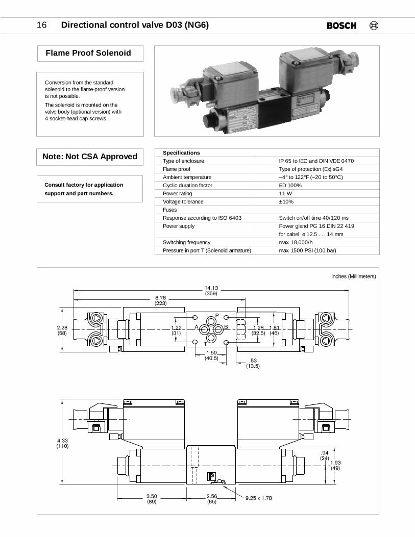
Flame Proof Solenoid
Specifications
Type of enclosure IP 65 to IEC and DIN VDE 0470
Flame proof Type of protection (Ex) sG4
Ambient temperature –4° to 122°F (–20 to 50°C)
Cyclic duration factor ED 100%
Power rating 11 W
Voltage tolerance ±10%
Fuses
Response according to ISO 6403 Switch on/off time 40/120 ms
Power supply Power gland PG 16 DIN 22 419
for cabel ø 12.5 . . . 14 mm
Switching frequency max. 18,000/h
Pressure in port T (Solenoid armature) max. 1500 PSI (100 bar)
Conversion from the standardsolenoid to the flame-proof versionis not possible.
The solenoid is mounted on the valve body (optional version) with 4 socket-head cap screws.
14.13(359)
8.78(223)
.53(13.5)
1.59(40.5)
1.28(32.5)
1.81(46)
1.22(31)
2.28(58)
4.33(110)
3.50(89)
2.56(65)
1.93(49)
.94(24)
9.25 x 1.78
A
T
P
B
Inches (Millimeters)
Note: Not CSA Approved
Consult factory for application
support and part numbers.
Directional control valve D03 (NG6) 17
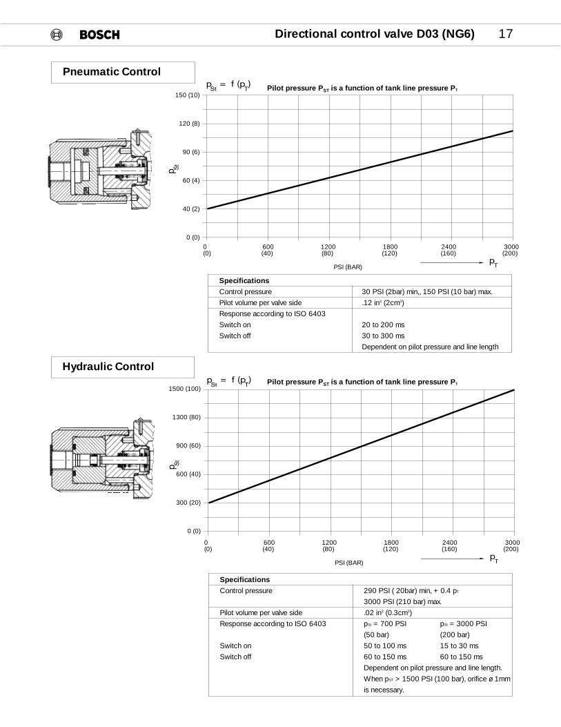
Pneumatic Control
Specifications
Control pressure 30 PSI (2bar) min,, 150 PSI (10 bar) max.
Pilot volume per valve side .12 in3 (2cm3)
Response according to ISO 6403
Switch on 20 to 200 ms
Switch off 30 to 300 ms
Dependent on pilot pressure and line length
Hydraulic Control
Specifications
Control pressure 290 PSI ( 20bar) min, + 0.4 pT
3000 PSI (210 bar) max.
Pilot volume per valve side .02 in3 (0.3cm3)
Response according to ISO 6403 pSt = 700 PSI pSt = 3000 PSI
(50 bar) (200 bar)
Switch on 50 to 100 ms 15 to 30 ms
Switch off 60 to 150 ms 60 to 150 ms
Dependent on pilot pressure and line length.
When pST > 1500 PSI (100 bar), orifice ø 1mm
is necessary.
p = f (p )St T
pT
p St
150 (10)
120 (8)
90 (6)
60 (4)
40 (2)
0 (0)0 600 1200 1800 2400 3000(0) (40) (80) (120) (160) (200)
PSI (BAR)
p = f (p )St T
pT
p St
1500 (100)
1300 (80)
900 (60)
600 (40)
300 (20)
0 (0)
0 600 1200 1800 2400 3000(0) (40) (80) (120) (160) (200)
PSI (BAR)
Pilot pressure PST is a function of tank line pressure PT
Pilot pressure PST is a function of tank line pressure PT
18 Directional control valve D03 (NG6)
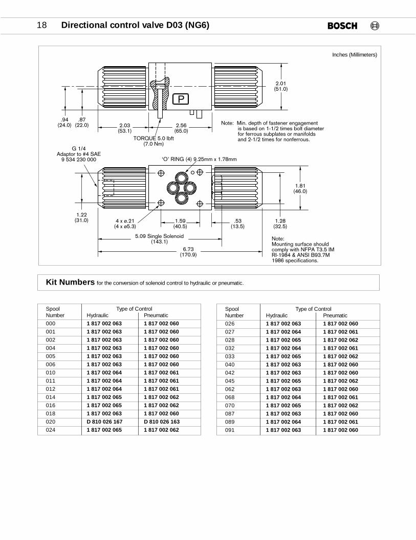
P
2.56(65.0)
2.03(53.1)
2.01(51.0)
.87(22.0)
.94(24.0)
TORQUE 5.0 lbft(7.0 Nm)
‘O’ RING (4) 9.25mm x 1.78mm
1.81(46.0)
1.28(32.5)
1.22(31.0) 1.59
(40.5).53
(13.5)4 x ø.21
(4 x ø5.3)
5.09 Single Solenoid(143.1)
6.73(170.9)
Note:Mounting surface shouldcomply with NFPA T3.5 IMRI-1984 & ANSI B93.7M 1986 specifications.
Note: Min. depth of fastener engagement is based on 1-1/2 times bolt diameter for ferrous subplates or manifolds and 2-1/2 times for nonferrous.
G 1/4Adaptor to #4 SAE
9 534 230 000
Inches (Millimeters)
Spool Type of ControlNumber Hydraulic Pneumatic
000 1 817 002 063 1 817 002 060001 1 817 002 063 1 817 002 060002 1 817 002 063 1 817 002 060004 1 817 002 063 1 817 002 060005 1 817 002 063 1 817 002 060006 1 817 002 063 1 817 002 060010 1 817 002 064 1 817 002 061011 1 817 002 064 1 817 002 061012 1 817 002 064 1 817 002 061014 1 817 002 065 1 817 002 062016 1 817 002 065 1 817 002 062018 1 817 002 063 1 817 002 060020 D 810 026 167 D 810 026 163024 1 817 002 065 1 817 002 062
Spool Type of ControlNumber Hydraulic Pneumatic
026 1 817 002 063 1 817 002 060027 1 817 002 064 1 817 002 061028 1 817 002 065 1 817 002 062032 1 817 002 064 1 817 002 061033 1 817 002 065 1 817 002 062040 1 817 002 063 1 817 002 060042 1 817 002 063 1 817 002 060045 1 817 002 065 1 817 002 062062 1 817 002 063 1 817 002 060068 1 817 002 064 1 817 002 061070 1 817 002 065 1 817 002 062087 1 817 002 063 1 817 002 060089 1 817 002 064 1 817 002 061091 1 817 002 063 1 817 002 060
Kit Numbers for the conversion of solenoid control to hydraulic or pneumatic.

Directional control valve D03 (NG6) 19
DirectionalControl Valve
MechanicalOperated
.39(10)
1.59(40.5)
1.28(32.5)
1.81(46)
1.22(31)
.43(11)
5.04(128)
.87(22)
1.77(45)
2.46(62.4)
STROKE
.79(20)
.35(9)
.35°max.
1.59(40.5)
2.56(65) 9.25 x 1.78
.51(13)
1.47(37.4)
1.93(49)
.87(22)
.94(24)
.47(12)
ø.21(5.3)
A
T
P
B
Inches (Millimeters)
F = lbs (N )
pT
FOR
CE
(tank pressure)
50 (200)
40 (160)
30 (120)
20 (80)
10 (40)
0 (0)0 300 900 1500 2100 2700
(20) (60) (100) (140) (180)
PSI (BAR)

20 Directional control valve D03 (NG6)
DirectionalControl Valve
ManualOperated
1.59(40.5)
1.28(32.5)
1.81(46)
1.22(31)
.53(13.5)
5.80(147.3)
6.30 max.(160)
A
T
P
B
1.14(29)
2.56(65)
9.25 x 1.78
1.93(49)
.87(22)
.94(24)
ø.21(5.3)
7.36(187)
2.41(61.2)
1.73(43.9)
.23°max.
a
.23°max.
b
Inches (Millimeters)
Specifications
Actuating force 7.8 lbs. (35 N)
Angular movement +_23°
Lever 1 813 501 002
Knob 1 813 231 007

Directional control valve D03 (NG6) 21
When a subplate is not used a machined pad must be provided.The mounting surface should comply with NFPA T3.5.1M R1- 1984
and ANSI B93.7M - 1986specifications.
Subplates, Bottom Ported
Inches (Millimeters)
AP
TB
B T
.548(13.9)
3.716(94.4)
2.814(72.1) 2.130
(54)
.50(12.7)
1.50(38.1)
A
1.423(36.1)
B
3.490(88.6)
2.410(61.2)
1.320(33.5)
4.62(117.3)
.359(9.1)
Bottom PortedPort A B PartSize in(mm) in(mm) Number
1/4" NPTF 2.017 .829 9 000 010 148(51.2) (21.0)
3/8" NPTF 2.079 .766 9 000 010 146(52.8) (19.5)
1/2" NPTF 2.130 .710 9 000 010 139(54.1) (18.0)
#6 SAE 2.050 .797 9 000 010 144(52.0) (20.2)
#8 SAE 2.130 .710 9 000 010 140(54.1) (18.0)
.343 Drill Thru2 Places
Note: Max. pressure = 4600 psi (315 BAR)

22 Directional control valve D03 (NG6)
TB
P A
Subplates, Side Ported
Inches (Millimeters)
.850(21.59)
A.850
(21.59)
3.716(94.13)
.343 Drill Thru2 Places
3.59(9.12)
2.84(72.14) 2.130
(54.10)
.548(13.92)
.5(12.7).850
(21.59)
1.50(38.1)
2.174(55.22)
1.609(40.87)
.850(21.59)
4.62(117.35)
Side PortedPort A PartSize in(mm) Number
1/4" NPTF .474 9 000 010 147(12.0)
3/8" NPTF .474 9 000 010 145(12.0)
1/2" NPTF .579 9 000 010 142(14.7)
#6 SAE .474 9 000 010 143(12.0)
#8 SAE .579 9 000 010 141(14.7)
Note: Max. pressure = 4600 psi (315 BAR)
When a subplate is not used a machined pad must be provided.The mounting surface should comply with NFPA T3.5.1M R1- 1984
and ANSI B93.7M - 1986specifications.
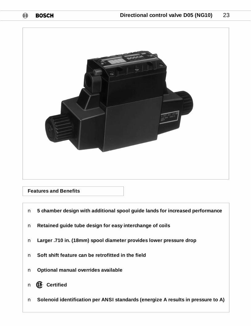
Directional control valve D05 (NG10) 23
Features and Benefits
n 5 chamber design with additional spool guide lands for increased performance
n Retained guide tube design for easy interchange of coils
n Larger .710 in. (18mm) spool diameter provides lower pressure drop
n Soft shift feature can be retrofitted in the field
n Optional manual overrides available
n Certified
n Solenoid identification per ANSI standards (energize A results in pressure to A)
®
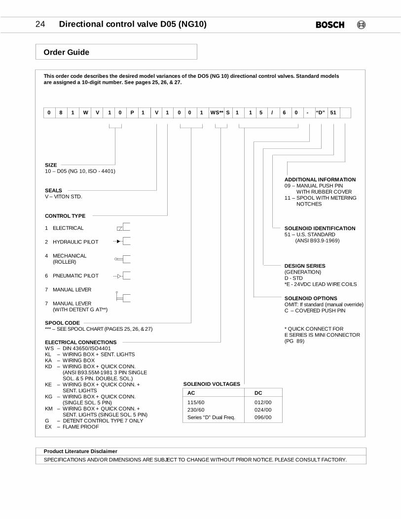
This order code describes the desired model variances of the DO5 (NG 10) directional control valves. Standard models are assigned a 10-digit number. See pages 25, 26, & 27.
SIZE10 – D05 (NG 10, ISO - 4401)
SEALSV – VITON STD.
CONTROL TYPE
1 ELECTRICAL
2 HYDRAULIC PILOT
4 MECHANICAL(ROLLER)
6 PNEUMATIC PILOT
7 MANUAL LEVER
7 MANUAL LEVER(WITH DETENT G AT**)
SPOOL CODE*** – SEE SPOOL CHART (PAGES 25, 26, & 27)
ELECTRICAL CONNECTIONSWS – DIN 43650/ISO4401KL – WIRING BOX + SENT. LIGHTSKA – WIRING BOXKD – WIRING BOX + QUICK CONN.
(ANSI B93.55M-1981 3 PIN SINGLE SOL. & 5 PIN. DOUBLE. SOL.)
KE – WIRING BOX + QUICK CONN. + SENT. LIGHTS
KG – WIRING BOX + QUICK CONN. (SINGLE SOL. 5 PIN)
KM – WIRING BOX + QUICK CONN. + SENT. LIGHTS (SINGLE SOL. 5 PIN)
G – DETENT CONTROL TYPE 7 ONLYEX – FLAME PROOF
24 Directional control valve D05 (NG10)
0 8 1 W V 1 0 P 1 V 1 0 0 1 WS** S 1 1 5 / 6 0 - “D” 51
SOLENOID VOLTAGES
AC DC
115/60 012/00230/60 024/00Series “D” Dual Freq. 096/00
ADDITIONAL INFORMATION09 – MANUAL PUSH PIN
WITH RUBBER COVER11 – SPOOL WITH METERING
NOTCHES
SOLENOID IDENTIFICATION51 – U.S. STANDARD
(ANSI B93.9-1969)
DESIGN SERIES(GENERATION)D - STD*E - 24VDC LEAD WIRE COILS
SOLENOID OPTIONSOMIT: If standard (manual override)C – COVERED PUSH PIN
* QUICK CONNECT FORE SERIES IS MINI CONNECTOR(PG 89)
Order Guide
Product Literature Disclaimer
SPECIFICATIONS AND/OR DIMENSIONS ARE SUBJECT TO CHANGE WITHOUT PRIOR NOTICE. PLEASE CONSULT FACTORY.

Directional control valve D05 (NG10) 25
KA KD KE KG KL KM WS WS --D11
SPOOL SYMBOLS TRANSITION 110/115 110/115 110/115 110/115 110/115 110/115 110/115 12 VDC. 12 VDC.NO. 220/230 220/230 220/230 220/230 220/230 220/230 220/230 24 VDC. 24 VDC.
024/00 024/00 024/00 96 VDC. 96 VDC.
Z069 Z201 Z267 Z135 Z003 Z397 Z463000 Z102 Z234 Z300 Z168 Z036 Z430 Z467
Z484**
Z070 Z202 Z268 Z136 Z004 Z398 Z464001 Z103 Z235 Z301 Z169 Z037 Z431 Z468
Z490 Z485**
Z071 Z203 Z269 Z137 Z005 Z399002* Z104 Z236 Z302 Z170 Z038 Z432
Z526 Z480**
Z072 Z204 Z270 Z138 Z006 Z400004 Z105 Z237 Z303 Z171 Z039 Z433 Z498
Z529 Z491 Z472
Z073 Z205 Z271 Z139 Z007 Z401005 Z106 Z238 Z304 Z172 Z040 Z434
Z489
Z074 Z206 Z272 Z140 Z008 Z402006 Z107 Z239 Z305 Z173 Z041 Z435
Z075 Z207 Z273 Z333 Z141 Z365 Z009 Z403010 Z108 Z240 Z306 Z349 Z174 Z381 Z042 Z436
Z508
Z076 Z208 Z274 Z334 Z142 Z366 Z010 Z404 Z465011 Z109 Z241 Z307 Z350 Z175 Z382 Z043 Z437 Z469
Z481**
Z077 Z209 Z275 Z335 Z143 Z367 Z011 Z405012 Z110 Z242 Z308 Z351 Z176 Z383 Z044 Z438
Z513 Z493 Z471
Z078 Z210 Z276 Z336 Z144 Z368 Z012 Z406014* Z111 Z243 Z309 Z352 Z177 Z384 Z045 Z439
Z482**
Z079 Z211 Z277 Z337 Z145 Z369 Z013 Z407016 Z112 Z244 Z310 Z353 Z178 Z385 Z046 Z440
Z080 Z212 Z278 Z146 Z014 Z408 Z466018 Z113 Z245 Z311 Z179 Z047 Z441 Z470
Z492 Z483**
Z081 Z213 Z279 Z147 Z015 Z409020 Z114 Z246 Z312 Z180 Z048 Z442
Z528 Z494 Z525**
Z082 Z214 Z280 Z338 Z148 Z370 Z016 Z410024 Z115 Z247 Z313 Z354 Z181 Z386 Z049 Z443
Z494
P T
A B
P T
A B
P T
A B
P T
A B
P T
A B
P T
A B
P T
A B
P T
A B
P T
A B
P T
A B
P T
A B
P T
A B
Standard types are assigned a 10-digit part number. Describe unassigned valve combinations with the alpha-numeric order code.
9 810 232Z…
KA – WIRING BOXKD – WIRING BOX + QUICK CONNECT (BRAD HARR. 3 PIN SING. & 5 PIN DBL. SOL.)KE – WIRING BOX + QUICK CONNECT + SENTINEL LIGHTSKG – WIRING BOX + QUICK CONNECT (SINGLE SOLENOID 5 PIN)KL – WIRING BOX + SENTINEL LIGHTSKM – WIRING BOX + QUICK CONNECT + SENTINEL LIGHTS (SINGLE SOL. 5 PIN)WS – PLUG CONNECTER (DIN 43650 / ISO 4401)D11 – SPOOL WITH METERING NOTCHES
* Metering notches Std.** Soft shift with 1 mm orifice
Part Numbers
P T
A B

26 Directional control valve D05 (NG10)
KA KD KE KG KL KM WS WS --D11
SPOOLSYMBOLS TRANSITION
110/115 110/115 110/115 110/115 110/115 110/115 110/115 12 VDC. 12 VDC.NO. 220/230 220/230 220/230 220/230 220/230 220/230 220/230 24 VDC. 24 VDC.
96 VDC. 96 VDC.
Z083 Z215 Z281 Z149 Z017 Z411026 Z116 Z248 Z314 Z182 Z050 Z444
Z084 Z216 Z282 Z339 Z150 Z371 Z018 Z412027 Z117 Z249 Z315 Z355 Z183 Z387 Z051 Z445
Z488 Z487028
Z085 Z217 Z283 Z340 Z151 Z372 Z019 Z413031 Z118 Z250 Z316 Z356 Z184 Z388 Z052 Z446
Z086 Z218 Z284 Z341 Z152 Z373 Z020 Z414032 Z119 Z251 Z317 Z357 Z185 Z389 Z053 Z447
Z087 Z219 Z285 Z342 Z153 Z374 Z021 Z415033 Z120 Z252 Z318 Z358 Z186 Z390 Z054 Z448
Z088 Z220 Z286 Z154 Z022 Z416040 Z121 Z253 Z319 Z187 Z055 Z449
Z089 Z221 Z287 Z155 Z023 Z417041 Z122 Z254 Z320 Z188 Z056 Z450
Z090 Z222 Z288 Z156 Z024 Z418042 Z123 Z255 Z321 Z189 Z057 Z451
Z091 Z223 Z289 Z343 Z157 Z375 Z025 Z419045 Z124 Z256 Z322 Z359 Z190 Z391 Z058 Z452
Z092 Z224 Z290 Z158 Z026 Z420062 Z125 Z257 Z323 Z191 Z059 Z453
Z093 Z225 Z291 Z344 Z159 Z376 Z027 Z421068 Z126 Z258 Z324 Z360 Z192 Z392 Z060 Z454
Z094 Z226 Z292 Z345 Z160 Z377 Z028 Z422070 Z127 Z259 Z325 Z361 Z193 Z393 Z061 Z455
Z095 Z227 Z293 Z346 Z161 Z378 Z029 Z423074 Z128 Z260 Z326 Z362 Z194 Z394 Z062 Z456
Z096 Z228 Z294 Z162 Z030 Z424087 Z129 Z261 Z327 Z195 Z063 Z457
Z097 Z229 Z295 Z347 Z163 Z379 Z031 Z425088 Z130 Z262 Z328 Z363 Z196 Z395 Z064 Z458
Z098 Z230 Z296 Z164 Z032 Z426091 Z131 Z263 Z329 Z197 Z065 Z459
Z099 Z231 Z297 Z165 Z033 Z427095 Z132 Z264 Z330 Z198 Z066 Z460
Z100 Z232 Z298 Z348 Z166 Z380 Z034 Z428923 Z133 Z265 Z331 Z364 Z199 Z396 Z067 Z461
Z101 Z233 Z299 Z167 Z035 Z429930 Z134 Z266 Z332 Z200 Z068 Z462
Pressure port leakagebleeds to tank in thecenter position
P T
A B
P T
A B
P T
A B
P T
A B
P T
A B
P T
A B
P T
A B
P T
A B
P T
A B
P T
A B
P T
A B
P T
A B
P T
A B
P T
A B
P T
A B
P T
A B
P T
A B
P T
A B
P T
A B
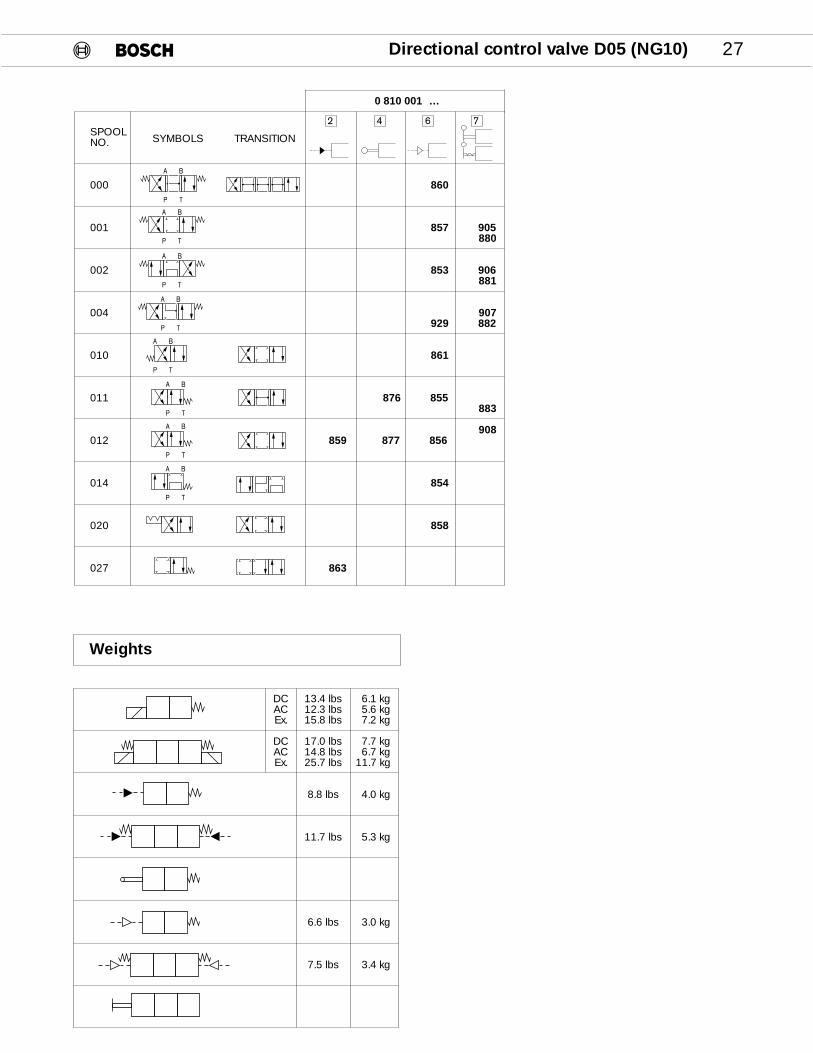
SPOOLSYMBOLS TRANSITIONNO.
000 Z860
001 Z857 Z905Z880
002 Z853 Z906Z881
004 Z907Z929 Z882
010 Z861
011 Z876 Z855Z883
Z908012 Z859 Z877 Z856
014 Z854
020 Z858
027 Z863
Directional control valve D05 (NG10) 27
DC 13.4 lbs 6.1 kgAC 12.3 lbs 5.6 kgEx. 15.8 lbs 7.2 kg
DC 17.0 lbs 7.7 kgAC 14.8 lbs 6.7 kgEx. 25.7 lbs 11.7 kg
8.8 lbs 4.0 kg
11.7 lbs 5.3 kg
6.6 lbs 3.0 kg
7.5 lbs 3.4 kg
2 4 6 7
0 810 001Z…
Weights
P T
A B
P T
A B
P T
A B
P T
A B
P T
A B
P T
A B
P T
A B
P T
A B
28 Directional control valve D05 (NG10)
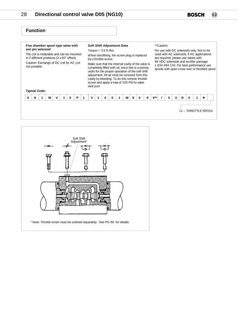
Five chamber spool type valve withwet pin solenoid
The coil is rotateable and can be mountedin 3 different positions (3 x 90° offset).
Caution: Exchange of DC coil for AC coilnot possible.
Typical Code:
Soft Shift Adjustment Data
Torque = 3.5 ft./lbs.
When retrofitting, the screw plug is replacedby a throttle screw.
Make sure that the internal cavity of the valve iscompletely filled with oil, since this is a prereq-uisite for the proper operation of the soft shiftadjustment. All air must be removed from thiscavity by bleeding. To do this remove throttlescrew and apply a max of 100 PSI to valvetank port.
**Caution:
For use with DC solenoids only. Not to beused with AC solenoids. If AC applications are required, please use valves with 96 VDC solenoids and rectifier package 1 834 484 134. For best performance usespools with open cross over or throttled spool.
11 – THROTTLE SPOOL
0 8 1 W V 1 0 P 1 V 1 0 0 1 W S 0 9 6** / 0 0 D 5 1 *
Function
Soft ShiftAdjustment*
* Note: Throttle screw must be ordered separately. See PG 88 for details.
Directional control valve D05 (NG10) 29
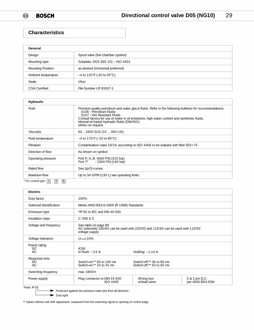
Electric
Duty factor 100%
Solenoid identification Meets ANSI B93.9-1969 (R 1988) Standards
Enclosure type *IP 65 to IEC and DIN 40 050
Insulation class C VDE § 5
Voltage and frequency See table on page 88AC-solenoids 230/60 can be used with 220/50 and 115/60 can be used with 110/50 voltage supply
Voltage tolerance UNOM±10%
Power ratingDC 42WAC In Rush: ~3.5 A Holding: ~1.14 A
Response timeDC Switch-on:** 65 to 100 ms Switch-off:** 30 to 80 msAC Switch-on:** 10 to 25 ms Switch-off:** 50 to 65 ms
Switching frequency max. 1800/h
Power supply Plug connector to DIN 43 650 Wiring box 5 & 3 pin Q.C.ISO 4400 w/lead wires per ANSI B93.55M
Hydraulic
Fluid Premium quality petroleum and water glycol fluids. Refer to the following bulletins for recommendations:S106 - Petroleum FluidsS107 - Fire Resistant Fluids
Consult factory for use of water in oil emulsions, high water content and synthentic fluids.Mineral-oil based hydraulic-fluids (DIN/ISO) others on request
Viscosity 60…1600 SUS (10 …350 cSt)
Fluid temperature –4 to 175°F (–20 to 80°C)
Filtration Contamination class 19/16, according to ISO 4406 to be realized with filter ß25=75
Direction of flow As shown on symbol
Operating pressure Port P, A, B: 4600 PSI (315 bar)Port T* : 2300 PSI (160 bar)
Rated flow See ∆p/Q-curves
Maximum flow Up to 34 GPM (130 L) see operating limits
General
Design Spool valve (five chamber system)
Mounting type Subplate, DO5 (NG 10) – ISO 4401
Mounting Position as desired (Horizontal preferred)
Ambient temperature –4 to 120°F (-20 to 50°C)
Seals Viton
CSA Certified File Number LR 93267-1
*Note: IP 65
** Valves without soft shift adjustment, measured from the switching signal to opening of control edge.
1 2 6
Protected against low pressure water jets from all direction
Dust tight
Characteristics
* For control type

30 Directional control valve D05 (NG10)
Valve Pressure vs. Flow Performances
Curve Reference Numbers
Spool Curve NumbersNumber
SpoolNumber PA PB AT BT PT
000 2 2 1 3 –
001 3 3 3 3 –
002 3 2 1 4 8
004 3 3 1 7 –
005 2 2 3 4 –
006 2 2 3 3 6
010 3 3 7 6 –
011 5 3 3 4 –
012 3 3 4 8 –
014 3 – – 4 8
016 3 – – 3 –
018 3 3 3 4 –
020 3 3 7 6 –
024 – 3 1 7 –
026 3 3 1 3 –
027 3 – – 6 –
031 – 3 3 – –
032 1 4 – – –
033 – 2 1 – –
040 2 5 3 – –
041 2 4 1 – –
042 3 3 3 2 –
045 – 3 3 – –
062 4 2 – 7 –
068 3 3 – – –
070 3 – – 3 –
074 2 – – 3 –
087 3 7 6 – –
088 – – – – –
091 1 2 1 4 –
095 1 1 1 6 8
923
930
290(20)
260(18)
230(16)
200(14)
175(12)
145(10)
116(8)
87(6)
58(4)
29(2)
0(0)
0(0) 5.5(20) 10.5(40) 16.0(60) 21.0(80) 26.0(100) 32.0(120) 34.0(130)
FLOW GPM(L/M)
PRESSUREPSI(BAR)
PRESSURE vs. FLOW CURVES
8
7
6
5
43
2
1
Performance Characteristics
A B
P T
A B
P T
A B
P T
Note: Viscosity = 164 SUS (35 Centistokes)
Directional control valve D05 (NG10) 31
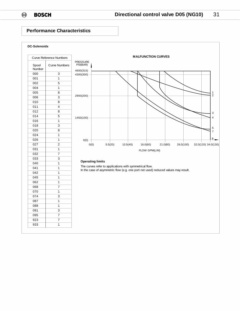
Operating limits
The curves refer to applications with symmetrical flow.In the case of asymmetric flow (e.g. one port not used) reduced values may result.
DC-Solenoids
4600(315)4300(300)
2900(200)
1450(100)
0(0)
12
3
4
57
8
Curve Reference Numbers
Spool Curve NumbersNumber
000 3
001 1
002 5
004 1
005 8
006 3
010 8
011 4
012 8
014 5
016 1
018 3
020 8
024 1
026 1
027 2
031 1
032 7
033 3
040 1
041 1
042 1
045 1
062 1
068 7
070 1
074 3
087 1
088 1
091 3
095 7
923 7
933 1
0(0) 5.5(20) 10.5(40) 16.0(60) 21.0(80) 26.0(100) 32.0(120) 34.0(130)
FLOW GPM(L/M)
PRESSUREPSI(BAR)
MALFUNCTION CURVES
Performance Characteristics
32 Directional control valve D05 (NG10)
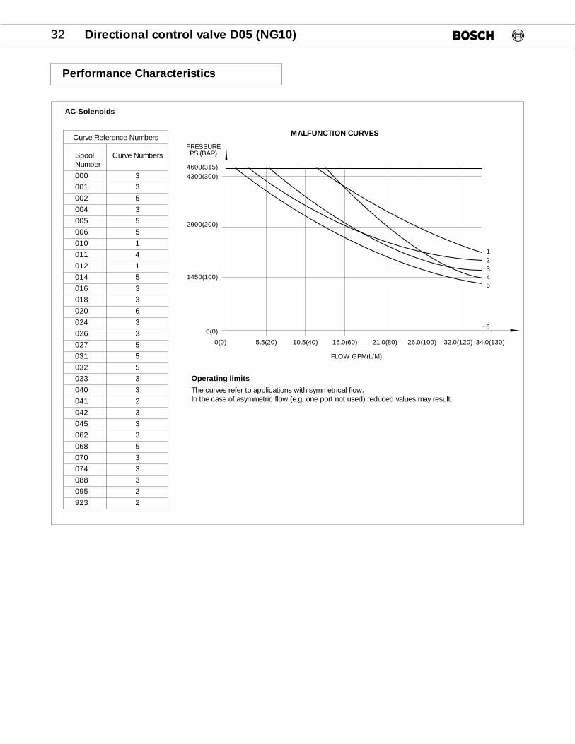
Operating limits
The curves refer to applications with symmetrical flow.In the case of asymmetric flow (e.g. one port not used) reduced values may result.
AC-Solenoids
4600(315)4300(300)
2900(200)
1450(100)
0(0)
Performance Characteristics
Curve Reference Numbers
Spool Curve NumbersNumber
000 3
001 3
002 5
004 3
005 5
006 5
010 1
011 4
012 1
014 5
016 3
018 3
020 6
024 3
026 3
027 5
031 5
032 5
033 3
040 3
041 2
042 3
045 3
062 3
068 5
070 3
074 3
088 3
095 2
923 2
0(0) 5.5(20) 10.5(40) 16.0(60) 21.0(80) 26.0(100) 32.0(120) 34.0(130)
FLOW GPM(L/M)
PRESSUREPSI(BAR)
MALFUNCTION CURVES
12345
6

Directional control valve D05 (NG10) 33
Valve With DC Solenoid DIN
*Bolt length change from series “B”.
Note: Min. depth of fastener engagement is basedon 1 1/2 times bolt dia. for ferrous subplates ormanifolds and 2 1/2 times for nonferrous.
Note: Clearance to remove coil 3.66 (93)
Optional manual push pins
Covered1 833 343 002
With rubber cover1 833 343 003
Clearance needed to remove connector
.47(12)
AB
4.65(118)
1.18 *(30)
ManualPush Pin
12.32(313)
5.12(130)
T
B
P
A
.47(12)
.31(8)
1.10(28)
1.37(35)
2.75(70)
1.53(38.9)
8.43 Single Solenoid(214)
Torque Bolts (4)100 in. lbs. (11+3Nm)
‘O’ Ring (5) 12 mm x 2 mm 1 520 210 115Torque 70 in. lbs. (8 Nm)
Inches (Millimeters)Seal Kit 9 810 232 520
Note: Mounting surface should comply with NFPA T3.51M R1-1984 ANSI B93.7M-1986 specifications.

34 Directional control valve D05 (NG10)
Valve With AC Solenoid DIN
Optional manual push pins
Covered1 833 343 002
With rubber cover1 833 343 003
Inches (Millimeters)
Clearance needed toremove connector
.47(12)
4.60(117)
1.18 *(30)
ManualPush Pin
10.20(259)
4.06(103)
T
B
P
A
.47(12)
.31(8)
1.10(28)
1.37(35)
2.75(70)
1.53(38.9)
7.36 Single Solenoid(187)
Torque Bolts (4)100 in. lbs. (11+3Nm)
‘O’ Ring (5) 12 mm x 2 mm 1 520 210 115Torque 70 in. lbs. (8 Nm)
AB
*Bolt length change from series “B”.
Note: Min. depth of fastener engagement is basedon 1 1/2 times bolt dia. for ferrous subplates ormanifolds and 2 1/2 times for nonferrous.
Note: Clearance to remove coil 2.75 (70)
Seal Kit 9 810 232 520
Note: Mounting surface should comply with NFPA T3.51M R1-1984 ANSI B93.7M-1986 specifications.
Directional control valve D05 (NG10) 35
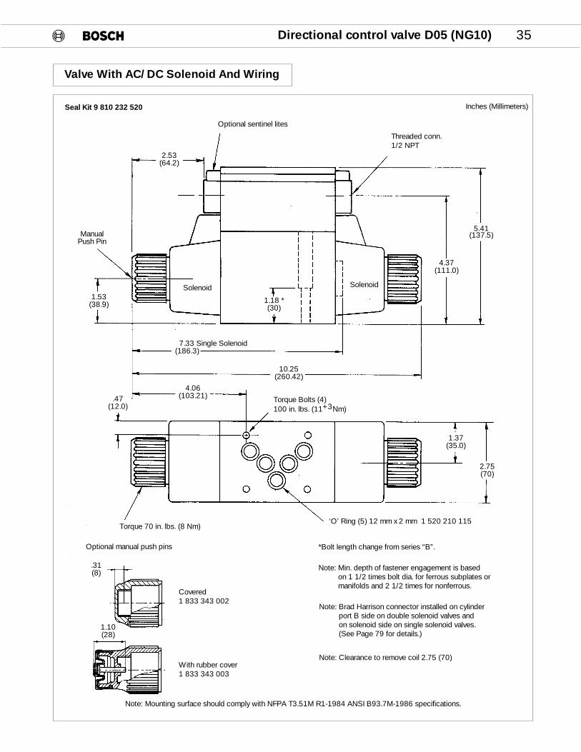
Valve With AC/DC Solenoid And Wiring
Inches (Millimeters)
Optional manual push pins
Threaded conn.1/2 NPT
Optional sentinel lites
5.41(137.5)
4.37(111.0)
1.18 *(30)
ManualPush Pin
10.25(260.42)
4.06(103.21).47
(12.0)
.31(8)
1.10(28)
1.37(35.0)
2.75(70)
1.53(38.9)
2.53(64.2)
7.33 Single Solenoid(186.3)
SolenoidSolenoid
Torque Bolts (4)100 in. lbs. (11+3Nm)
‘O’ Ring (5) 12 mm x 2 mm 1 520 210 115Torque 70 in. lbs. (8 Nm)
*Bolt length change from series “B”.
Note: Min. depth of fastener engagement is basedon 1 1/2 times bolt dia. for ferrous subplates ormanifolds and 2 1/2 times for nonferrous.
Seal Kit 9 810 232 520
Note: Brad Harrison connector installed on cylinder port B side on double solenoid valves and on solenoid side on single solenoid valves.(See Page 79 for details.)
Note: Clearance to remove coil 2.75 (70)
Note: Mounting surface should comply with NFPA T3.51M R1-1984 ANSI B93.7M-1986 specifications.
Covered1 833 343 002
With rubber cover1 833 343 003

36 Directional control valve D05 (NG10)
Flame Proof Solenoid
Not CSA Approved.
Consult factory for applicationsupport and part numbers.
A.C. Solenoid D.C. Solenoid
110/50 024/00
220/50 110/00
190/00
Specifications
Type of enclosureIP 65 to IEC and DIN 40 050Type of protection (Ex) sG4
Ambient temperature –4° to 110°F (–20 to 40°C)
Cyclic duration factor ED 100%
Power rating 20 W
Insulation clas C VDE 100 § 5
Voltage tolerance ±10%
Switch on/off time 100/40 ms
Power supply Power gland PG 16 DIN 22 419
Switching frequency max. 8000/h
Pressure in port T max. 1000 PSI (70 bar)
7.00 (178)
3.66 (93)
Ground–terminal
Emergency manual control
4.92 (125) 2.31 (58,7)
2.76(70)
.83(21)
2.76(70)
.57(14,5)
.99
(25,
2)
M5
1.26
Ø(3
2)
1.52
(38,
1)
1.30
(32.
5)2.
69(6
8,2)
.24
Ø(6
)
3.98
(101
)
3.13
(79.
4)
2.76
Ø(7
0)
+_ 0 ,15
+_ 0 ,2
–0
,1
.69(17,6)
.39(10 )
Directional control valve D05 (NG10) 37
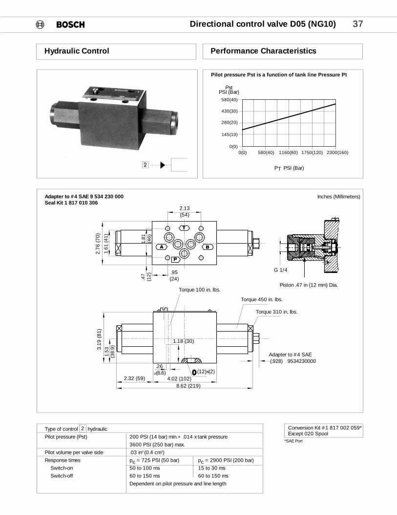
Hydraulic Control
Pilot pressure Pst is a function of tank line Pressure Pt
Performance Characteristics
Type of control hydraulic
Pilot pressure (Pst) 200 PSI (14 bar) min.+ .014 x tank pressure
3600 PSI (250 bar) max.
Pilot volume per valve side .03 in3 (0.4 cm3)
Response times pc = 725 PSI (50 bar) pc = 2900 PSI (200 bar)
Switch-on 50 to 100 ms 15 to 30 ms
Switch-off 60 to 150 ms 60 to 150 ms
Dependent on pilot pressure and line length
2
580(40)
430(30)
280(20)
145(10)
0(0)0(0) 580(40) 1160(80) 1750(120) 2300(160)
PstPSI (Bar)
PT PSI (Bar)
Piston .47 in (12 mm) Dia.
h2
2.13(54)
2.32 (59) 4.02 (102)8.62 (219)
(12)x(2)
.95(24)
.26Ø(6.6)
Adapter to #4 SAE(.928) 9534230000
1.81
(46)
1.53
(38.
9)
.47
(12)
2.76
(70)
3.19
(81)
1.61
(41)
Torque 100 in. lbs.
Torque 450 in. lbs.
Torque 310 in. lbs.
Inches (Millimeters)Adapter to #4 SAE 9 534 230 000Seal Kit 1 817 010 306
T
B
P
A
1.18 (30)
G 1/4
Conversion Kit #1 817 002 059*Except 020 Spool
*SAE Port
38 Directional control valve D05 (NG10)
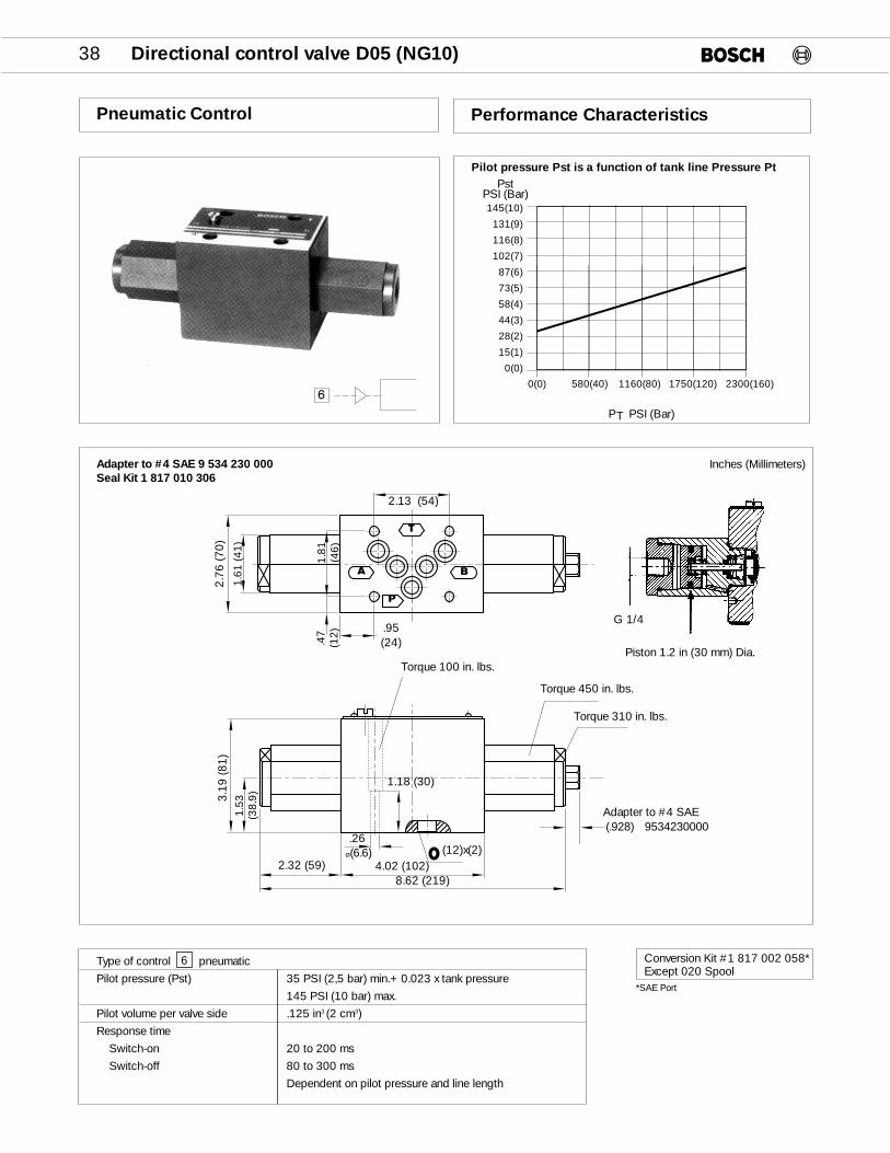
Pneumatic Control
Pilot pressure Pst is a function of tank line Pressure Pt
Performance Characteristics
Type of control pneumatic
Pilot pressure (Pst) 35 PSI (2,5 bar) min.+ 0.023 x tank pressure
145 PSI (10 bar) max.
Pilot volume per valve side .125 in3 (2 cm3)
Response time
Switch-on 20 to 200 ms
Switch-off 80 to 300 ms
Dependent on pilot pressure and line length
6
145(10)
131(9)
116(8)
102(7)
87(6)
73(5)
58(4)
44(3)
28(2)
15(1)
0(0)
PT PSI (Bar)
0(0) 580(40) 1160(80) 1750(120) 2300(160)
PstPSI (Bar)
p6
Piston 1.2 in (30 mm) Dia.
2.13 (54)
2.32 (59) 4.02 (102)8.62 (219)
(12)x(2)
.95(24)
T
B
P
A
.26Ø(6.6)
Adapter to #4 SAE(.928) 9534230000
1.81
(46)
1.53
(38.
9)
.47
(12)
2.76
(70)
3.19
(81)
1.61
(41)
Torque 100 in. lbs.
Torque 450 in. lbs.
Torque 310 in. lbs.
Inches (Millimeters)Adapter to #4 SAE 9 534 230 000Seal Kit 1 817 010 306
1.18 (30)
G 1/4
Conversion Kit #1 817 002 058*Except 020 Spool
*SAE Port
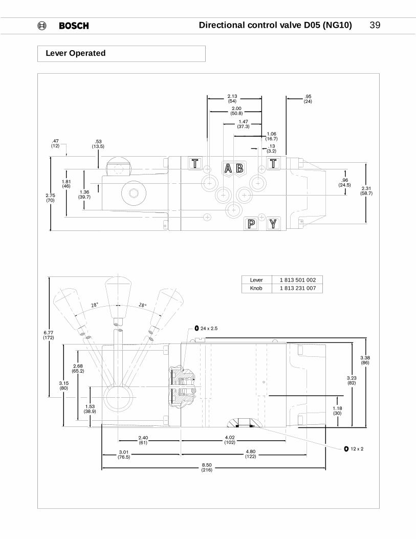
Directional control valve D05 (NG10) 39
Lever Operated
��
�
�
����
28° 28°
8.50(216)
4.80(122)
4.02(102)
2.40(61)
3.01(76.5)
6.77(172)
3.15(80)
2.68(65.2)
1.53(38.9)
1.18(30)
3.23(82)
3.38(86)
2.75(70)
1.81(46)
1.36(39.7)
.53(13.5)
.47(12)
2.13(54)
2.00(50.8)
1.47(37.3)
1.06(16.7)
.13(3.2)
.95(24)
.96(24.5)
2.31(58.7)
24 x 2.5
12 x 2
Lever 1 813 501 002
Knob 1 813 231 007
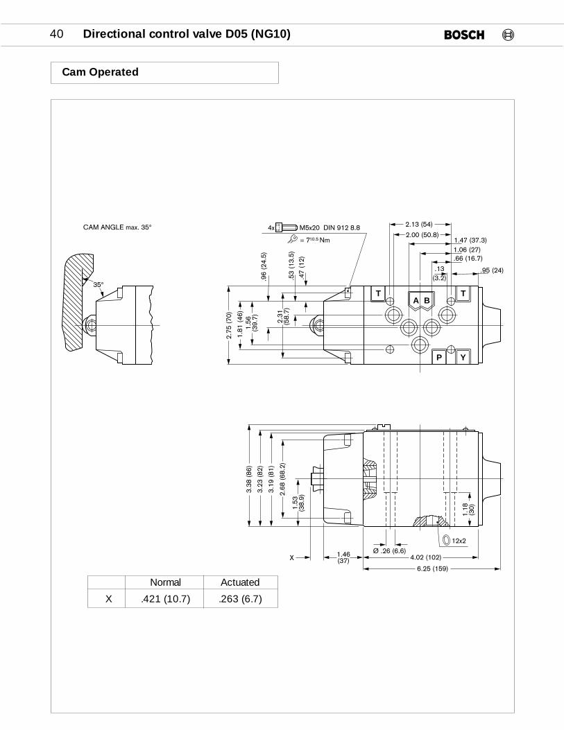
40 Directional control valve D05 (NG10)
Cam Operated
T T
YP
A B
4x M5x20 DIN 912 8.8
= 7 Nm10.5
2.13 (54)
2.00 (50.8)1.47 (37.3)1.06 (27).66 (16.7)
.95 (24).13(3.2)
2.75
(70
)
1.56
(39.
7).9
6 (2
4.5)
2.31
(58.
7)
.47
(12)
.53
(13.
5)
3.38
(86
)
3.23
(82
)
3.19
(81
)
2.68
(68
.2)
1.53
(38.
9)
X 1.46(37)
Ø .26 (6.6)4.02 (102)
6.25 (159)
12x2
35°
1.81
(46
)
CAM ANGLE max. 35°
1.18
(30)
Normal Actuated
X .421 (10.7) .263 (6.7)

Directional control valve D05 (NG10) 41
Bolt Kit
Subplate
When a subplate is not used a machined pad must be provided.The mounting surface should comply with NFPA T3.5.1M R1-1984 ANSI B93.7M-1986 specification.
NOTE: Max. Pressure = 4600 PSI(315 Bar)
Port Size Part Number
1/2" NPT 9 000 010 172
3/4" NPT 9 000 010 181
8 SAE 9 000 010 174
12 SAE 9 000 010 183
Kit Part Number
B-180 valve only 953 675
Subplates, Bottom Ported
Inches (Millimeters)
2.125(53.98)
1.470(37.34)
1.063(27.0)
.660(16.76)
.130(3.3)
2.043(51.89)
.625(15.88)
2.812(71.42)
3.44(87.38)
.413 (10.5) Dia. 4 Holes
1.125(28.58)
.250(6.35)
.840(21.34) 1.280
(32.51)
.50(12.7)
1.812(46.02)
6.210(157.73)
1.81(45.97)
4.06(103.12)
4.625(117.48)
3.125(79.38)
1.625(41.28)
2.875(73.03)
2.030(51.56)
1.186(30.12)
5.344(135.74)
4.34(110.24)
.438(11.12)
Subplate mountingholes (2).344 (87.4) Dia. Thru
Valve Mounting Holes (4)1/4" – 20 unc, .69 (17.5) deep

42 Directional control valve D05 (NG10)
Subplates, Side Ported
Bolt Kit
Subplate
When a subplate is not used a machined pad must be provided.The mounting surface should comply with NFPA T3.5.1M R1-1984 ANSI B93.7M-1986 specification.
NOTE: Max. Pressure = 4600 PSI(315 Bar)
Port Size Part Number
1/2" NPT 9 000 010 164
3/4" NPT 9 000 010 166
8 SAE 9 000 010 165
12 SAE 9 000 010 175
Kit Part Number
B-180 valve only 953 675
Inches (Millimeters)
.938(23.82)
.750(19.05)
1.281(32.54)
PT
A B
.413 (10.5) Dia. 4 Holes
2.125(53.98)
1.470(37.34)
1.063(27.0)
.660(16.76)
.130(3.3)
2.043(51.89)
.625(15.88)
4.06(103.12)
2.812(71.42)
3.44(87.38)
.840(21.34) 1.280
(32.51)
1.125(28.58)
.250(6.35)
1.812(46.02)
.438(11.12)
4.34(110.24)
5.344(135.74)
Valve Mounting Holes (4)1/4" – 20 unc, .69 (17.5) deep
2.063(52.4)
.792(20.12)
.938(23.82)
1.81(45.97)
6.21(157.73)
.50(12.7)
Subplatemountingholes (2).344 (87.4)Dia. Thru
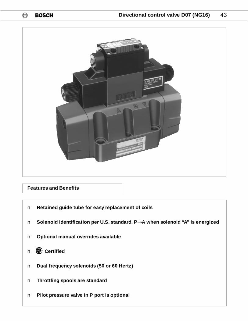
Directional control valve D07 (NG16) 43
Features and Benefits
n Retained guide tube for easy replacement of coils
n Solenoid identification per U.S. standard. P➝A when solenoid “A” is energized
n Optional manual overrides available
n Certified
n Dual frequency solenoids (50 or 60 Hertz)
n Throttling spools are standard
n Pilot pressure valve in P port is optional
®

44 Directional control valve D07 (NG16)
This order code describes the desired model variances of the DO7 (NG 16) directional control valves. Standard models are assigned a 10-digit number. See page 45.
SIZE16 – D07 (NG 16)
SEALSV – VITON STD.
CONTROL TYPE
2 – HYDRAULIC
3 – ELECTRICAL
SPOOL CODE
REFER TO SPOOL CHART ON PAGE 45
PILOT CHOKES*
F – FIXED
T – ADJUSTABLE
R – PILOT PRESSURE VALVE IN P*
H – ADJUSTABLE SPOOL STOPS*
PILOT AND DRAINXY– EXT. PILOT EXT. DRAINPT – INT. PILOT INT. DRAINPY – INT. PILOT EXT. DRAINXT – EXT. PILOT INT. DRAIN
ELECTRICAL CONNECTIONSWS – DIN 43650/ISO4400 KL – WIRING BOX + SENT. LIGHTSKA – WIRING BOXKD – WIRING BOX + QUICK CONN.
(ANSI B93.55m – 1981 3 PIN SINGLE SOL. & 5 PIN. DOUBLE. SOL.)
KE – WIRING BOX + QUICK CONN. + SENT. LIGHTS
KG – WIRING BOX + QUICK CONN. (SINGLE SOL. 5 PIN)
KM – WIRING BOX + QUICK CONN. + SENT. LIGHTS (SINGLE SOL. 5 PIN)
EX – FLAME PROOF SOLENOID
0 8 1 W V 1 6 P 1 V 3 D 5 1 /
SOLENOID VOLTAGES
AC DC
115/60 012/00230/60 024/00Series “D” Dual Frequency
09 – MANUAL PUSH PINWITH RUBBER COVER*
51 – SOLENOIDIDENTIFICATION PER U.S.STANDARD P➝A WHENSOLENOID “A” IS ENER-GIZED (ANSI B93.9)
D – DESIGN SERIESD - STD**E - 24VDC LEAD WIRE COILS
SOLENOID OPTIONS*
C – COVERED PUSH PIN
** QUICK CONNECT FORE SERIES IS MINICONNECTOR (PG 89)
Order Code
Product Literature Disclaimer
SPECIFICATIONS AND/OR DIMENSIONS ARE SUBJECT TO CHANGE WITHOUT PRIOR NOTICE. PLEASE CONSULT FACTORY.
* If these options are not needed, omit them from the code

Directional control valve D07 (NG16) 45
KA KD KE KG KL KM WS WS
SPOOL SYMBOLS TRANSITION PILOT 110/115 110/115 110/115 110/115 110/115 110/115 110/115 24 VDC.NO. & DRAIN
000 XY Z033 Z047 Z059 Z005 Z020
PY Z104 Z099XY Z034 Z048 Z060 Z006 Z021
001 PT Z035 Z049 Z061 Z007 Z022HXY Z008 Z023FXT Z076 Z103FPT Z036 Z009
002 XY Z037 Z050 Z062 Z010 Z024
XY Z038 Z051 Z063 Z011 Z025XT Z071
004 PT Z039 Z052 Z064 Z012 Z026FPT Z040 Z013FXY Z077
009 XY Z041 Z053 Z065 Z014 Z027
XY Z042 Z054 Z066 Z015 Z028
010 PT Z043 Z055 Z067 Z082 Z016 Z029PY Z085XT Z092PY Z110
018 XY Z044 Z056 Z068 Z017 Z030PT Z089XY Z045 Z057 Z069 Z018 Z031
020 FPY Z019 Z097PT Z046 Z058 Z070 Z032PT Z098PY Z081026 XY Z083
FPY Z079PT Z072
042 FPT Z075PY Z087PT Z073
045 FPT Z074
P T
A B
P T
A B
P T
A B
Standard valves are assigned a 10-digit part number. Describe unassigned valve combinations with the alpha-numeric order code.
9 810 234Z…
KA –WIRING BOXKD –WIRING BOX + QUICK CONNECT (3 PIN SINGLE &
5 PIN DOUBLE SOLENOID)KE –WIRING BOX + QUICK CONNECT + SENTINEL LIGHTSKG –WIRING BOX + QUICK CONNECT (SINGLE SOLENOID 5 PIN)KL – WIRING BOX + SENTINEL LIGHTSKM– WIRING BOX + QUICK CONNECT + SENTINEL LIGHTS
(SINGLE SOL. 5 PIN)WS–PLUG CONNECTER (DIN 43650 / ISO 4400)
Part Numbers
P T
A B
P T
A B
P T
A B
P T
A B
P T
A B
P T
A B
P T
A B
P T
A B
P– INT.PILOT
X– EXT.PILOT
T – INT.DRAIN
Y– EXT.DRAIN
46 Directional control valve D07 (NG16)
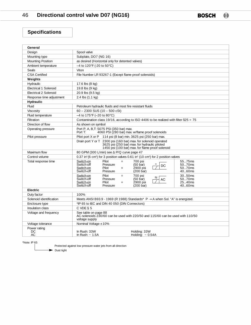
GeneralDesign Spool valve Mounting type Subplate, DO7 (NG 16)Mounting Position as desired (Horizontal only for detented valves)Ambient temperature –4 to 120°F (-20 to 50°C)Seals VitonCSA Certified File Number LR 93267-1 (Except flame proof solenoids)WeightsHydraulic 17.6 lbs (8 kg) Electrical 1 Solenoid 19.8 lbs (9 kg) Electrical 2 Solenoid 20.9 lbs (9.5 kg)Response time adjustment 2.4 lbs (1.1 kg)HydraulicFluid Petroleum hydraulic fluids and most fire resistant fluidsViscosity 60 – 2300 SUS (10 – 500 cSt)Fluid temperature –4 to 175°F (–20 to 80°C)Filtration Contamination class 19/16, according to ISO 4406 to be realized with filter ß25 = 75Direction of flow As shown on symbolOperating pressure Port P, A, B,T: 5075 PSI (350 bar) max.
Port T: 4060 PSI (280 bar) max. w/flame proof solenoids Pilot pressure Pilot port X or P 114 psi (8 bar) min. 3625 psi (250 bar) max.
Drain port Y or T 2300 psi (160 bar) max. for solenoid operated3625 psi (250 bar) max. for hydraulic piloted1450 psi (100 bar) max. for flame proof solenoid
Maximum flow 80 GPM (300 L/min) see ∆ P/Q curve page 47Control volume 0.37 in3 (6 cm3) for 3 position valves 0.61 in3 (10 cm3) for 2 position valvesTotal response time Switch-on Pilot = 700 psi 55...75ms
Switch-off Pressure (50 bar) 50...70msSwitch-on Pilot = 2900 psi 50...70msSwitch-off Pressure (200 bar) 40...60msSwitch-on Pilot = 700 psi 30...50msSwitch-off Pressure (50 bar) 50...70msSwitch-on Pilot = 2900 psi 25...40msSwitch-off Pressure (200 bar) 40...60ms
ElectricDuty factor 100% Solenoid identification Meets ANSI B93.9 - 1969 (R 1988) Standards* P ➝ A when Sol. “A” is energized.Enclosure type *IP 65 to IEC and DIN 40 050 (DIN Connectors)Insulation class C VDE § 5Voltage and frequency See table on page 88
AC-solenoids 230/60 can be used with 220/50 and 115/60 can be used with 110/50 voltage supply
Voltage tolerance Nominal Voltage ±10%Power rating
DC In Rush: 33W Holding: 33WAC In Rush: ~ 1.5A Holding: ~ 0.54A
Specifications
*Note: IP 65Protected against low pressure water jets from all direction
Dust tight
DC=
AC≈
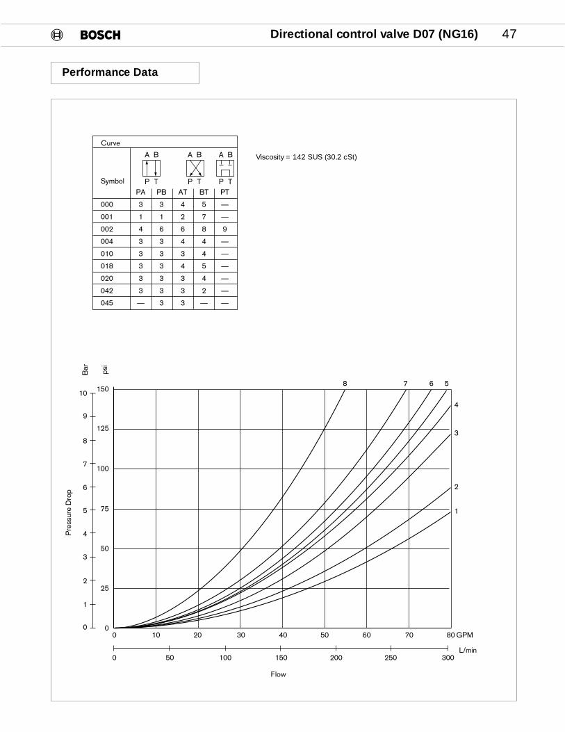
Directional control valve D07 (NG16) 47
Performance Data
Viscosity = 142 SUS (30.2 cSt)
150
125
100
75
50
25
00 10 20 30 40 50 60 70 80 GPM
10
9
8
7
6
5
4
3
2
1
0
0 50 100 150 200 250 300L/min
Flow
Pre
ssur
e D
rop
Bar psi
A B
P T
A B
P T
A B
P TSymbol
000
001
002
004
010
018
020
042
045
PA
3
1
4
3
3
3
3
3
—
PB
3
1
6
3
3
3
3
3
3
AT
4
2
6
4
3
4
3
3
3
BT
5
7
8
4
4
5
4
2
—
PT
—
—
9
—
—
—
—
—
—
Curve
8 7 6 5
4
3
2
1
48 Directional control valve D07 (NG16)
Sol A Sol B
X YP T1 2
43
P
T
TvPv
12x
Y
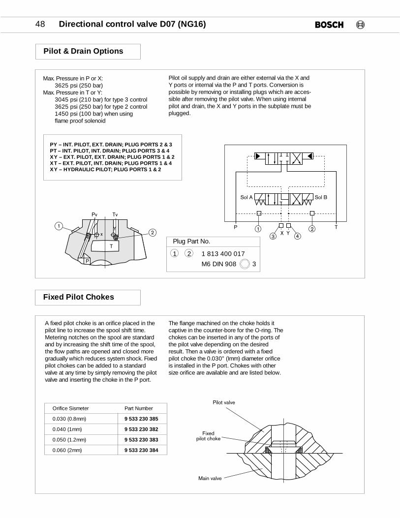
Pilot & Drain Options
Fixed Pilot Chokes
Pilot valve
Fixedpilot choke
Main valve
PY – INT. PILOT, EXT. DRAIN; PLUG PORTS 2 & 3PT – INT. PILOT, INT. DRAIN; PLUG PORTS 3 & 4XY – EXT. PILOT, EXT. DRAIN; PLUG PORTS 1 & 2XT – EXT. PILOT, INT. DRAIN; PLUG PORTS 1 & 4XY – HYDRAULIC PILOT; PLUG PORTS 1 & 2
Orifice Sismeter Part Number
0.030 (0.8mm) 9 533 230 385
0.040 (1mm) 9 533 230 382
0.050 (1.2mm) 9 533 230 383
0.060 (2mm) 9 533 230 384
Max. Pressure in P or X:3625 psi (250 bar)
Max. Pressure in T or Y:3045 psi (210 bar) for type 3 control3625 psi (250 bar) for type 2 control1450 psi (100 bar) when using flame proof solenoid
Pilot oil supply and drain are either external via the X andY ports or internal via the P and T ports. Conversion ispossible by removing or installing plugs which are acces-sible after removing the pilot valve. When using internalpilot and drain, the X and Y ports in the subplate must beplugged.
A fixed pilot choke is an orifice placed in thepilot line to increase the spool shift time.Metering notches on the spool are standardand by increasing the shift time of the spool,the flow paths are opened and closed moregradually which reduces system shock. Fixedpilot chokes can be added to a standardvalve at any time by simply removing the pilotvalve and inserting the choke in the P port.
The flange machined on the choke holds itcaptive in the counter-bore for the O-ring. Thechokes can be inserted in any of the ports ofthe pilot valve depending on the desiredresult. Then a valve is ordered with a fixedpilot choke the 0.030” (Imm) diameter orificeis installed in the P port. Chokes with othersize orifice are available and are listed below.
Plug Part No.
1 2 1 813 400 017
M6 DIN 908 3

Directional control valve D07 (NG16) 49
Adjustable Pilot Chokes
P T
SOL BSOL A
A B
X Y
TP
P T
SOL BSOL A
A B
X Y
TP
For Conversion
Description Part number
NG6 Flow control module w/seal plate (meter out) 9 810 161 089
Seal plate 1 811 037 800
4 x M5 x 70, DIN 912 – 10.9 (Part number is for one bolt) 2 910 151 180
METER-OUT(STANDARD)
METER-IN(TURN MODULAR VALVE 180º)
Adjustable chokes consist of a modular flowcontrol valve which contains two non-pressurecompensated throttle valves with free flowchecks. It provides independent control of thespool shift time in both direc-tions. Becausethe port pattern is symmet-rical and a sealplate is used, the module can be turned 180°to provide either meter-in or meter-out control.
Meter-out is standard. If meter-in is needed, thepilot valve must be removed and the flow con-trol module rotated 180° on its longitudi-nalaxis. The locating pin in the bottom mount-ingsurface of the flow control module must beremoved and installed on the opposite sidebefore reassembly. The seal plate alwaysremains on top of the main valve body. Torquevalue for the mounting bolts of the pilot valve is 5.0 lb/ft (7.0 Nm).
883
P T
BA
Pmax. 5000 psi
RACINE, WI U.S.A.
TB A
1.57(40.0)180°
PILOT CHOKEADJUSTING SCREW
(BOTH ENDS) 6mm

50 Directional control valve D07 (NG16)
Pilot Pressure Valve
0 100 200 300 L/min
GPM806040200
Flow
225
200
175
150
125
100
75
50
25
0
2
4
6
8
10
12
14
16
Bar
psi
Pre
ssur
e D
rop
Pv
Sol A Sol B
X YP T
DP
A B
The pilot pressure valve is a slip-in car-tridge which fits into a machined cavity inthe pressure port of the main valve. It isused to create pilot pressure when usingopen center spools (000 and 002). Pilotpressure is fed internally to the pilot valve.
The pressure drop across the pilot pres-sure valve is additive to the pressure dropacross the main valve. The machined cavity,to accept the pilot pressure cartridge, isstandard on all valves.
For Conversion
Description Part Number
Pilot pressure valve cartidge 1 817 419 037
Directional control valve D07 (NG16) 51
A B Y
Germany
7.95(202)
11.97(304)
4.02(102)
0.35(9)
Adjustment range
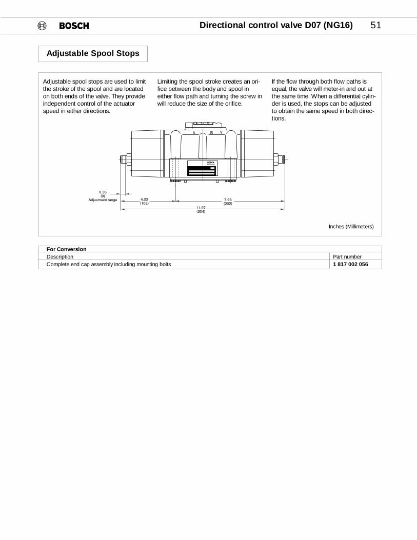
Adjustable Spool Stops
Inches (Millimeters)
For ConversionDescription Part numberComplete end cap assembly including mounting bolts 1 817 002 056
Adjustable spool stops are used to limitthe stroke of the spool and are locatedon both ends of the valve. They provideindependent control of the actuatorspeed in either directions.
Limiting the spool stroke creates an ori-fice between the body and spool ineither flow path and turning the screw inwill reduce the size of the orifice.
If the flow through both flow paths isequal, the valve will meter-in and out atthe same time. When a differential cylin-der is used, the stops can be adjustedto obtain the same speed in both direc-tions.
52 Directional control valve D07 (NG16)
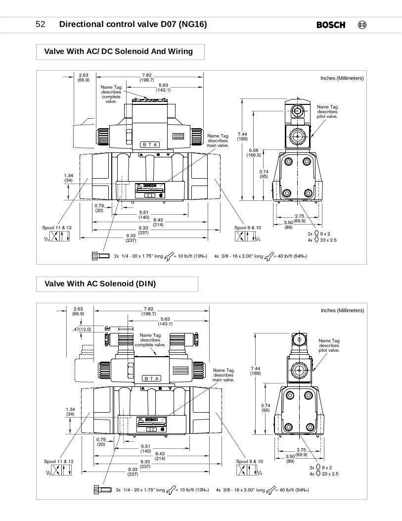
Valve With AC/DC Solenoid And Wiring
883
P T
BA
Pmax. 5000 psi
RACINE, WI U.S.A.
TB A
2x 9 x 24x 23 x 2.5
2x 1/4 - 20 x 1.75" long = 10 lb/ft (13Nm)
3.74(95)
5.51(140) 8.43
(214)
0.79(20)
1.34(34)
2.75(69.9)3.50
(89)
Name Tagdescribespilot valve.
7.44(189)
5.63(143.1)
7.82(198.7)
2.63(66.9)
Name Tagdescribesmain valve.
9.33(237)
9.33(237)
4x 3/8 - 16 x 2.00" long = 40 lb/ft (54Nm)
6.56(166.5)
Name Tagdescribescomplete
valve.
Spool 9 & 10Spool 11 & 12
Inches (Millimeters)
Valve With AC Solenoid (DIN)
883
P T
BA
Pmax. 5000 psi
RACINE, WI U.S.A.
AB T
2x 9 x 24x 23 x 2.5
2x 1/4 - 20 x 1.75" long = 10 lb/ft (13Nm)
3.74(95)
5.51(140) 8.43
(214)
0.79(20)
1.34(34)
2.75(69.9)3.50
(89)
Name Tagdescribespilot valve.
7.44(189)
5.63(143.1)
7.82(198.7)
2.63(66.9)
Name Tagdescribesmain valve.
9.33(237)
9.33(237)
4x 3/8 - 16 x 2.00" long = 40 lb/ft (54Nm)
Name Tagdescribes
complete valve.
Spool 9 & 10Spool 11 & 12
.47(12.0)
Inches (Millimeters)
Directional control valve D07 (NG16) 53
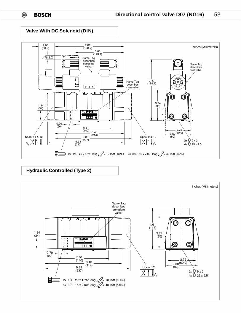
Valve With DC Solenoid (DIN)
883
P T
BA
Pmax. 5000 psi
RACINE, WI U.S.A.
TB A
2x 9 x 24x 23 x 2.5
2x 1/4 - 20 x 1.75" long = 10 lb/ft (13Nm)
3.74(95)
5.51(140) 8.43
(214)
0.79(20)
1.34(34)
2.75(69.9)3.50
(89)
Name Tagdescribespilot valve.
7.47(189.7)
5.63(143.1)
7.82(198.7)
2.63(66.9)
Name Tagdescribesmain valve.
9.33(237)
9.33(237)
4x 3/8 - 16 x 2.00" long = 40 lb/ft (54Nm)
Name Tagdescribescomplete
valve.
Spool 9 & 10Spool 11 & 12
.47(12.0)
Inches (Millimeters)
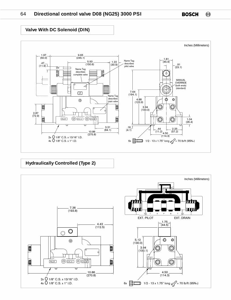
Hydraulic Controlled (Type 2)
883
P T
BA
Pmax. 5000 psi
RACINE, WI U.S.A.
2x 9 x 24x 23 x 2.5
2x 1/4 - 20 x 1.75" long = 10 lb/ft (13Nm)
3.74(95)
5.51(140) 8.43
(214)
0.79(20)
1.34(34)
2.75(69.9)3.50
(89)
Name Tagdescribescomplete
valve.
4x 3/8 - 16 x 2.00" long = 40 lb/ft (54Nm)
4.61(117)
9.33(237)
Spool 12
Inches (Millimeters)
54 Directional control valve D07 (NG16)
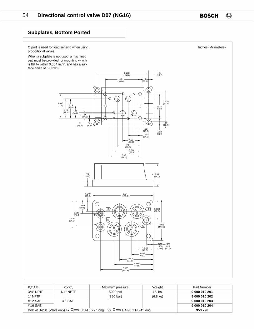
Subplates, Bottom Ported
C port is used for load sensing when usingproportional valves.
When a subplate is not used, a machinedpad must be provided for mounting whichis flat to within 0.004 in./in. and has a sur-face finish of 63 RMS.
Inches (Millimeters)
P,T,A,B, X,Y,C, Maximum pressure Weight Part Number3/4” NPTF 1/4” NPTF 5000 psi 15 lbs. 9 000 010 2011” NPTF (350 bar) (6.8 kg) 9 000 010 202#12 SAE #6 SAE 9 000 010 203#16 SAE 9 000 010 204 Bolt kit B-231 (Valve only) 4x 3/8-16 x 2” long 2x 1/4-20 x 1-3/4” long 953 726
3.315(84.2)
3.063(77.8)
1.558(39.6)
1.310(33.3)
2.62(64.0)
2.308(58.6)
SAE.750
(19.0)
4.62(117.3)
1.843(46.8)
2.468(62.7)
3.843(97.6)
4.468(113.5)
6.055(153.8)
6.94(176.3)
NPT.812
(20.6)
.75(19.0)
3.47(88.1)
3.016(76.6)
2.6(66.0)
1.97(50.0)
1.342(34.0)
.72(18.3)
.50(12.7)
.938(23.8)
3.625(92.1)
2.75(69.8)
.063(1.6)
.56(14.2)
.62(15.7)
1.37(34.8)
2.19(55.6)
2.25(57.1)
2.815(71.5)
5.938(150.8)
.5(12.7)
1.5(38.1)
4.0(101.6)
A
T
C
B
P
X
Y
Directional control valve D08 (NG25) 3000 PSI 55
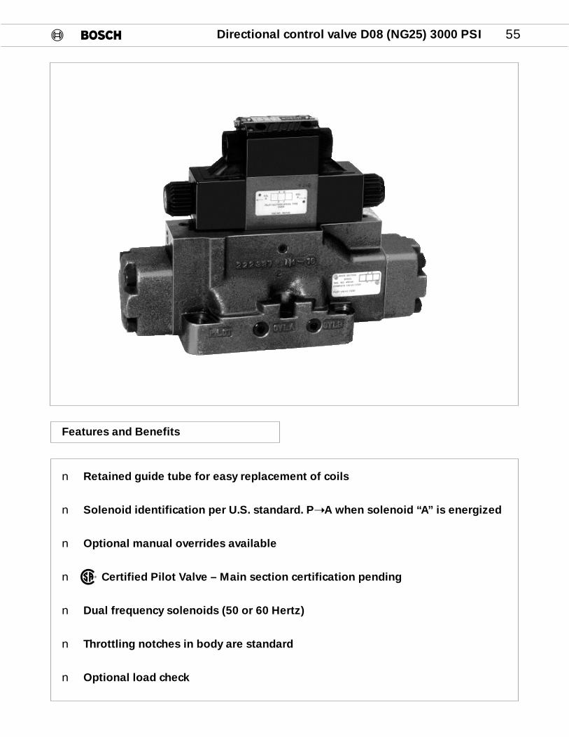
Features and Benefits
n Retained guide tube for easy replacement of coils
n Solenoid identification per U.S. standard. P➝A when solenoid “A” is energized
n Optional manual overrides available
n Certified Pilot Valve – Main section certification pending
n Dual frequency solenoids (50 or 60 Hertz)
n Throttling notches in body are standard
n Optional load check
®

56 Directional control valve D08 (NG25) 3000 PSI
Order Code
This order code describes the desired model variances of the DO8 (NG 25) directional control valves. Standard models are assigned a 10-digit number. See page 57.
SIZE06 – D08 (NG 25)
SEALSV – VITON STD.
CONTROL TYPE
2 – HYDRAULIC
3 – ELECTRICAL
SPOOL CODE
REFER TO SPOOL CHART ON PAGE 57
PILOT CHOKES*
F – FIXED
T – ADJUSTABLE
R – LOAD CHECK IN “P” PORT*
H – ADJUSTABLE SPOOL STOPS*
PILOT AND DRAINXY – EXT. PILOT EXT. DRAINPT – INT. PILOT INT. DRAINPY – INT. PILOT EXT. DRAINXT – EXT. PILOT INT. DRAIN
ELECTRICAL CONNECTIONSWS – DIN 43650/ISO4400 KL – WIRING BOX + SENT. LIGHTSKA – WIRING BOXKD – WIRING BOX + QUICK CONN.
(ANSI B93.55m – 1981 3 PIN SINGLE SOL. & 5 PIN. DOUBLE. SOL.)
KE – WIRING BOX + QUICK CONN. + SENT. LIGHTS
KG – WIRING BOX + QUICK CONN. (SINGLE SOL. 5 PIN)
KM – WIRING BOX + QUICK CONN. + SENT. LIGHTS (SINGLE SOL. 5 PIN)
EX – FLAME PROOF SOLENOID
0 8 1 W V 2 5 P 1 V 3 D 5 1 / 5 5 /
SOLENOID VOLTAGES
AC DC
115/60 012/00230/60 024/00Series “D” Dual Frequency
09 – MANUAL PUSH PINWITH RUBBER COVER*
55 – LOW PRESSUREVERSION
51 – SOLENOID IDENTIFICATIONPER U.S. STANDARD P›A WHEN SOLENOID “A” IS ENERGIZED (ANSI B93.9)
D – DESIGN SERIESD – STD**E – 24VDC LEAD WIRE COIL
SOLENOID OPTIONS*
C – COVERED PUSH PIN
** QUICK CONNECT FOR ESERIES IS MINI CONNECTOR(See PG 89)
Product Literature Disclaimer
SPECIFICATIONS AND/OR DIMENSIONS ARE SUBJECT TO CHANGE WITHOUT PRIOR NOTICE. PLEASE CONSULT FACTORY.
* If these options are not needed, omit them from the code

Directional control valve D08 (NG25) 3000 PSI 57
Part Numbers
KA KD KE KG KL KM WS WS
SPOOL SYMBOLS TRANSITION PILOT 110/115 110/115 110/115 110/115 110/115 110/115 110/115 24 VDC.NO. & DRAIN
PY Z506 Z529000 XY Z583
XT Z578
PT Z505 Z517 Z628 Z547 Z580001 PY Z553 Z576 Z631 Z536
XY Z629 Z626 Z588
PY Z507 Z530 Z649002 XY Z562 Z573 Z613
XT Z563 Z568 Z669
PT Z508 Z531 Z545 Z544 Z575
004 PY Z555 Z611 Z581 Z594XY Z667
FPY Z621
PT Z572005 PY Z608
XY Z564
PT Z532 Z582009 PY Z577
XY Z570 Z617 Z543
PT Z512 Z518 Z625 Z551 Z571PY Z558 Z537
010 XY Z560 Z627 Z668XT Z624
FPT Z659
PT Z511 Z643 Z550 Z549018 PY Z633 Z620
PT Z513 Z528 Z642 Z542 Z538020 XY Z561
PY Z675 Z639
PT Z510 Z548 Z612 Z587026 PY Z614
PT Z509042 XY Z674
FPT Z654
PY Z598 Z514 Z597D4 FPT Z660
P T
A B
P T
A B
P T
A B
P T
A B
P T
A B
Standard valves are assigned a 10-digit part number. Describe unassigned valve combinations with the alpha-numeric order code.
9 810 235Z…
KA –WIRING BOXKD –WIRING BOX + QUICK CONNECT (3 PIN SINGLE &
5 PIN DOUBLE SOLENOID)KE –WIRING BOX + QUICK CONNECT + SENTINEL LIGHTSKG –WIRING BOX + QUICK CONNECT (SINGLE SOLENOID 5 PIN)KL – WIRING BOX + SENTINEL LIGHTSKM – WIRING BOX + QUICK CONNECT + SENTINEL LIGHTS
(SINGLE SOL. 5 PIN)WS –PLUG CONNECTER (DIN 43650 / ISO 4400)
P T
A B
P T
A B
P T
A B
P T
A B
P T
A B
P T
A B
P T
A B
P T
A B
P – INT.PILOT
X – EXT.PILOT
T – INT.DRAIN
Y – EXT.DRAIN

58 Directional control valve D08 (NG25) 3000 PSI
Specifications
General
Design Spool valve
Mounting type Subplate, DO8 (NG 25)
Mounting Position as desired (Horizontal only for detented valves)
Ambient temperature –4 to 120°F (-20 to 50°C)
Seals Viton
CSA Certified File Number LR 93267-1 (Except flame proof solenoids)
Weights
Hydraulic 25.0 (11.3)
Electrical 1 Solenoid 26.6 (12.1)
Electrical 2 Solenoid 27.3 ( 12.4)
Adjustable Pilot Chokes 2.4 lbs (1.1kg)
Hydraulic
Fluid Petroleum hydraulic fluids and most fire resistant fluids
Viscosity 60 – 2300 SUS (10 – 500 cSt)
Fluid temperature –4 to 175°F (–20 to 80°C)
Filtration Contamination class 19/16, according to ISO 4406 to be realized with filter ß25=75
Direction of flow As shown on symbol
Operating pressure Port P, A, B,T: 3000 PSI (210 bar) max.Port T: 1500 PSI (100 bar) max. w/flame proof solenoids
Pilot pressure 65 PSI (4.5 bar)min. 3000 PSI (210 bar) max.
Maximum flow 75 GPM (284 L/min) see ∆ P/Q curve page 59
Control volume 0.5 in3 (8 cm3) for 3 position valves
Electric
Duty factor 100%
Solenoid identification Meets ANSI/B93.9 - 1969 (R 1988) Standards* P › A when Sol. “A” is energized.
Enclosure type *IP 65 to IEC and DIN 40 050 (DIN Connectors)
Insulation class C VDE § 5
Voltage and frequency See table on page 88AC-solenoids 230/60 can be used with 220/50 and 115/60 can be used with 110/50 voltage supply
Voltage tolerance Nominal Voltage ±10%
Power ratingDC In Rush: 33W Holding: 33WAC In Rush: ~ 1.5A Holding: ~ 0.54A
Response time 25 – 90ms Dependent on control pressure and spool
Switching frequency max. 1800/h
*Note: IP 65Protected against low pressure water jets from all direction
Dust tight
Directional control valve D08 (NG25) 3000 PSI 59
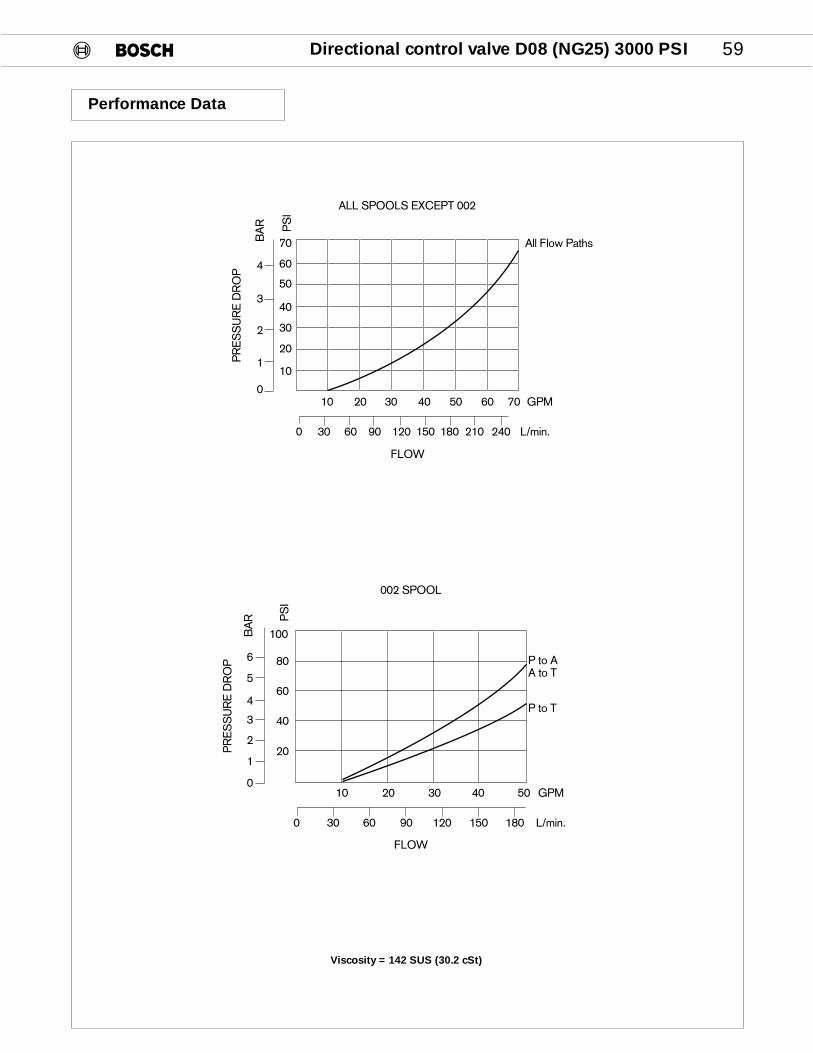
Performance Data
L/min.1801501209060300
10 20 30 40 50 GPM
P to AA to T
P to T
20
40
60
80
100
PS
I
0
1
2
4
3
5
6
BA
R
002 SPOOL
PR
ES
SU
RE
DR
OP
FLOW
10 20 30 40 50 60 70 GPM
120
30
40
50
60
70
PS
I
BA
R
PR
ES
SU
RE
DR
OP
2
3
4
0 30 60 90 120 150 180 210 240 L/min.
ALL SPOOLS EXCEPT 002
10
0
FLOW
All Flow Paths
Viscosity = 142 SUS (30.2 cSt)

60 Directional control valve D08 (NG25) 3000 PSI
Pressure Port Check
Pilot & Drain Options
1
2
3
A
PT
B
4
A B
X YP T
SOL BSOL A
Pressure PortCheck Cartridge
TOP VIEW WITH PILOT SECTION REMOVED
BOTTOM VIEW
PY – INT. PILOT, EXT. DRAIN; PLUG PORTS 2 & 3PT – INT. PILOT, INT. DRAIN; PLUG PORTS 3 & 4XY – EXT. PILOT, EXT. DRAIN; PLUG PORTS 1 & 2XT – EXT. PILOT, INT. DRAIN; PLUG PORTS 1 & 4XY – HYDRAULIC PILOT; PLUG PORTS 1 & 2
EXT. PILOT (X) EXT. DRAIN (Y)
T A P B T3 4
1 2
Pilot oil supply and drain are eitherexternal via the X and Y ports or inter-nal via the P and T ports. There are fourthreaded ports and only two plugs(1/16” NPT). The installations of theplugs determines the source of the
pilot oil and where it drains. Valves canbe converted in the field. Wheninstalling plugs in port 1 and 2, caremust be taken that the plug is screwedin all the way or both passages will beblocked.
The pressure port check is a loadcheck which prevents the load fromdropping when several valves are con-nected in parallel. It will not create pilotpressure for internal pilot when using
open center spools. The standard valvebody is not machined for the checkvalve cartridge.

Directional control valve D08 (NG25) 3000 PSI 61
Adjustable Pilot Chokes
P
CYL BCYL APILOT
8.33(211.6)
6.46(164.1)
3.94(100.0)
9.20(233.7)
4.78(123.9)
PILOT CHOKEADJUSTING SCREW
(BOTH ENDS)6mm
180°1.57
(40.0)
SEAL PLATE1 811 037 089
P T
SOL BSOL A
A B
X Y
TP
P T
SOL BSOL A
A B
X Y
TP
For Conversion
Description Part number
NG6 Flow control module w/seal plate (meter out) 9 810 161 089Seal plate 1 811 037 8004 x 10 – 24 x 2 3/4” Long (Bolt kit B-215) 953 710
METER-OUT(STANDARD)
METER-IN(TURN MODULAR VALVE 180º)
Adjustable chokes consist of a modular flowcontrol valve which contains two non-pressurecompensated throttle valves with free flowchecks. It provides independent control of thespool shift time in both direc-tions. Because theport pattern is symmet-rical and a seal plate isused, the module can be turned 180° to provideeither meter-in or meter-out control.
Meter-out is standard. If meter-in is needed, thepilot valve must be removed and the flow controlmodule rotated 180° on its longitudi-nal axis. Thelocating pin in the bottom mount-ing surface of theflow control module must be removed andinstalled on the opposite side before reassembly.The seal plate always remains on top of the mainvalve body. Torque value for the mounting bolts ofthe pilot valve is 5.0 lb/ft (7.0 Nm).
62 Directional control valve D08 (NG25) 3000 PSI
EXT. PILOT EXT. DRAIN
T A P B T
ADJUSTABLE SPOOL STOPS
Limit stroke at either end.Add 5" (127mm)to valve length.
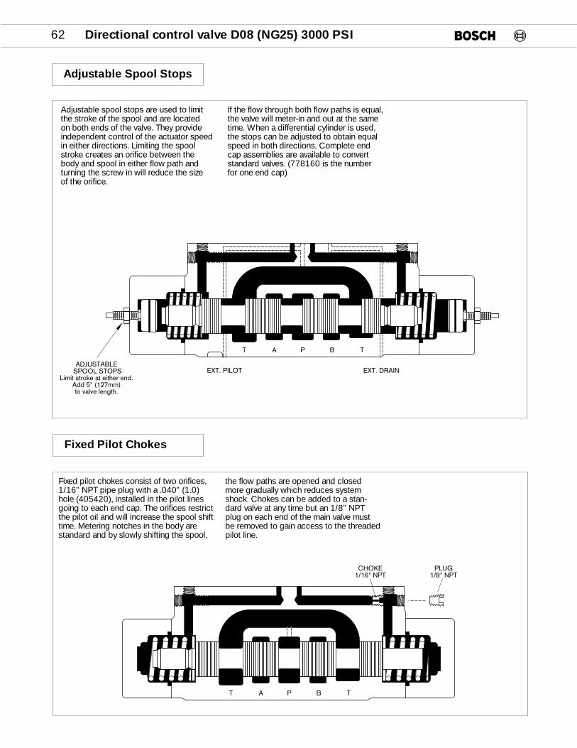
Adjustable Spool Stops
Fixed Pilot Chokes
T A P B T
PLUG1/8" NPT
CHOKE1/16" NPT
Adjustable spool stops are used to limit the stroke of the spool and are located on both ends of the valve. They provideindependent control of the actuator speedin either directions. Limiting the spoolstroke creates an orifice between the body and spool in either flow path andturning the screw in will reduce the size of the orifice.
If the flow through both flow paths is equal,the valve will meter-in and out at the sametime. When a differential cylinder is used,the stops can be adjusted to obtain equalspeed in both directions. Complete endcap assemblies are available to convertstandard valves. (778160 is the numberfor one end cap)
Fixed pilot chokes consist of two orifices,1/16” NPT pipe plug with a .040” (1.0)hole (405420), installed in the pilot linesgoing to each end cap. The orifices restrictthe pilot oil and will increase the spool shifttime. Metering notches in the body arestandard and by slowly shifting the spool,
the flow paths are opened and closedmore gradually which reduces systemshock. Chokes can be added to a stan-dard valve at any time but an 1/8” NPTplug on each end of the main valve mustbe removed to gain access to the threadedpilot line.
Directional control valve D08 (NG25) 3000 PSI 63
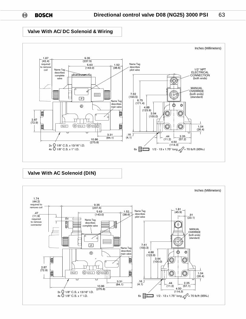
Valve With AC/DC Solenoid & Wiring
9.35(237.5)
5.63(143.0)
1.52(38.6)
.16(4.1)
7.62(193.5)
4.88(123.9)
3.94(100.0)
.44(11.2)
1.04(26.4)
4.50(114.3)
2.25(57.2)10.86
(275.8)
3.31(84.1)
2.87(72.9)
1.67(42.4)
requiredto remove
coil
6.75(171.4)
P
CYL BCYL APILOT
1/2" NPTELECTRICAL
CONNECTION(both ends)
MANUALOVERRIDE(both ends)(standard)
2x 1/8" C.S. x 13/16" I.D.4x 1/8" C.S. x 1" I.D. 1/2 - 13 x 1.75" long = 70 lb/ft (95Nm)6x
Name Tagdescribespilot valveName Tag
describescomplete
valve
Name Tagdescribesmain valve
Inches (Millimeters)
Valve With AC Solenoid (DIN)
PILOT CYL A CYL B
P
3.31(84.1)
10.86(275.8)
.44(11.2)
2.25(57.1)
4.50(114.3)
1.04(26.4)
3.94(100.0)
4.88(123.9)
.91(23.1)
1.81(45.9)
2.87(72.9)
1.52(38.6)
5.63(143.0)
9.35(237.5)
7.61(193.3)
.47(11.9)
requiredto removeconnector
1.74(44.2)
required toremove coil
.16(4.1)
MANUALOVERRIDE(both ends)(standard)
2x 1/8" C.S. x 13/16" I.D.4x 1/8" C.S. x 1" I.D. 1/2 - 13 x 1.75" long = 70 lb/ft (95Nm)6x
Name Tagdescribespilot valve
Name Tagdescribes
complete valve
Name Tagdescribesmain valve
Inches (Millimeters)
64 Directional control valve D08 (NG25) 3000 PSI
Valve With DC Solenoid (DIN)
P
CYL BCYL APILOT
9.65(245.1)
1.97(50.0)
.47(11.9)
5.93(150.6)
1.22(30.9)
1.81(45.9)
.91(23.1)
1.04(26.4)
.44(11.2)
.16(4.1)
7.64(194.1)
4.88(123.9)
3.94(100.0)
2.25(57.2)
4.50(114.3)
3.31(84.1)
10.86(275.8)
2.87(72.9)
MANUALOVERRIDE(both ends)(standard)
2x 1/8" C.S. x 13/16" I.D.4x 1/8" C.S. x 1" I.D. 1/2 - 13 x 1.75" long = 70 lb/ft (95Nm)6x
Name Tagdescribespilot valve
Name Tagdescribes
complete valve
Name Tagdescribesmain valve
Inches (Millimeters)
Hydraulically Controlled (Type 2)
CYL BCYL APILOT
3.94(100.1)
4.50(114.3)
10.86(270.8)
5.12(130.0)
4.43(112.5)
7.36(193.8)
1.75(44.5)
2x 1/8" C.S. x 13/16" I.D.4x 1/8" C.S. x 1" I.D. 1/2 - 13 x 1.75" long = 70 lb/ft (95Nm)6x
Inches (Millimeters)
EXT. PILOT EXT. DRAIN
T A P B T3 4
1 2

Directional control valve D08 (NG25) 65
Subplates, Bottom Ported
Inches (Millimeters)
C port is used for load sensing when using proportional valves.
C
X
A
T
BP
Y
5.125(130.2)
3.969(100.8)
3.719(94.5)
3.031(76.9)
2.094(53.2)
1.156(29.4)
4 HOLES.5625 DRILL THRU
3.625(92.1)
1.815(46.1)
.688(17.5)
1.183(30.0)
.75(19.0)
.188(4.8)
2.938(74.6)
4.5(114.3)
6.0(152.4)
6 HOLES1/2-13 UNC-2B THD
.94 ±.03 DEEP
7.680(195.1)
4.902(124.5)
1.805(45.8)
.530(13.5)
3.0(76.2)
.75(19.0)
1.371(34.8)
2.558(64.9)
3.496(88.8)
5.240(133.1)
6.178(156.9)
7.368(187.1)
1.938(49.2)
3.0(76.2)
1.628(41.3)
4.058(103.1)
4.368(110.9)
8.74(22.2)
0.224(5.7)
When a subplate is not used, a machined pad must be provided for mounting which is flat to within 0.0003 in./in. and has a surface finish of 63 RMS.
P,T,A,B X,Y,C Pmax PSI (bar) Weight Lbs. (kg) Part Number
1” NPTF 1/4”NPTF 5000 (350) (Subplate only) 25(11.3) 9 000 010 2161 1/4”NPTF 9 000 010 2171 1/2”NPTF 9 000 010 218#16 SAE #6 SAE 9 000 010 219#20 SAE 9 000 010 220#24 SAE 9 000 010 221Bolt kit B – 114 (valve only) 6x 1/2 – 13 x 1.75” Long 953594
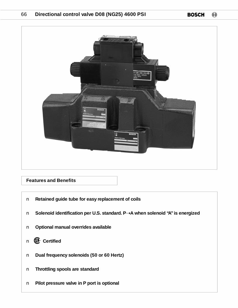
66 Directional control valve D08 (NG25) 4600 PSI
Features and Benefits
n Retained guide tube for easy replacement of coils
n Solenoid identification per U.S. standard. P➝A when solenoid “A” is energized
n Optional manual overrides available
n Certified
n Dual frequency solenoids (50 or 60 Hertz)
n Throttling spools are standard
n Pilot pressure valve in P port is optional
®
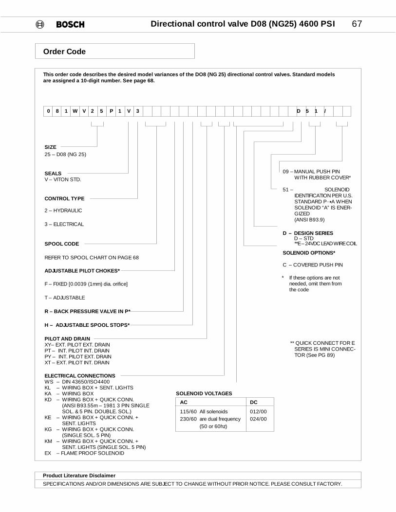
Directional control valve D08 (NG25) 4600 PSI 67
This order code describes the desired model variances of the DO8 (NG 25) directional control valves. Standard models are assigned a 10-digit number. See page 68.
SIZE25 – D08 (NG 25)
SEALSV – VITON STD.
CONTROL TYPE
2 – HYDRAULIC
3 – ELECTRICAL
SPOOL CODE
REFER TO SPOOL CHART ON PAGE 68
ADJUSTABLE PILOT CHOKES*
F – FIXED [0.0039 (1mm) dia. orifice]
T – ADJUSTABLE
R – BACK PRESSURE VALVE IN P*
H – ADJUSTABLE SPOOL STOPS*
PILOT AND DRAINXY– EXT. PILOT EXT. DRAINPT – INT. PILOT INT. DRAINPY – INT. PILOT EXT. DRAINXT – EXT. PILOT INT. DRAIN
ELECTRICAL CONNECTIONSWS – DIN 43650/ISO4400KL – WIRING BOX + SENT. LIGHTSKA – WIRING BOXKD – WIRING BOX + QUICK CONN.
(ANSI B93.55m – 1981 3 PIN SINGLE SOL. & 5 PIN. DOUBLE. SOL.)
KE – WIRING BOX + QUICK CONN. + SENT. LIGHTS
KG – WIRING BOX + QUICK CONN. (SINGLE SOL. 5 PIN)
KM – WIRING BOX + QUICK CONN. + SENT. LIGHTS (SINGLE SOL. 5 PIN)
EX – FLAME PROOF SOLENOID
0 8 1 W V 2 5 P 1 V 3 D 5 1 /
SOLENOID VOLTAGES
AC DC
115/60 All solenoids 012/00230/60 are dual frequency 024/00
(50 or 60hz)
09 – MANUAL PUSH PINWITH RUBBER COVER*
51 – SOLENOIDIDENTIFICATION PER U.S.STANDARD P➝A WHENSOLENOID “A” IS ENER-GIZED(ANSI B93.9)
D – DESIGN SERIESD – STD**E – 24VDC LEAD WIRE COIL
SOLENOID OPTIONS*
C – COVERED PUSH PIN
** QUICK CONNECT FOR ESERIES IS MINI CONNEC-TOR (See PG 89)
Order Code
Product Literature Disclaimer
SPECIFICATIONS AND/OR DIMENSIONS ARE SUBJECT TO CHANGE WITHOUT PRIOR NOTICE. PLEASE CONSULT FACTORY.
* If these options are not needed, omit them from the code
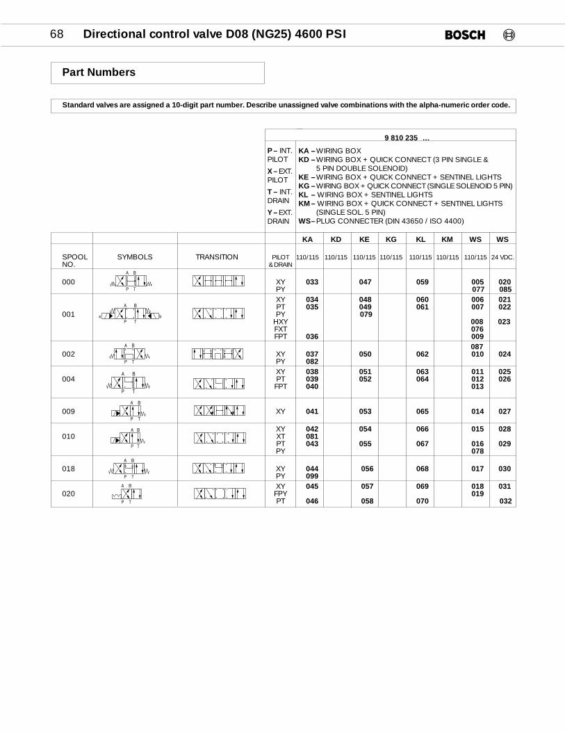
68 Directional control valve D08 (NG25) 4600 PSI
KA KD KE KG KL KM WS WS
SPOOL SYMBOLS TRANSITION PILOT 110/115 110/115 110/115 110/115 110/115 110/115 110/115 24 VDC.NO. & DRAIN
000 XY Z033 Z047 Z059 Z005 Z020PY Z077 Z085XY Z034 Z048 Z060 Z006 Z021PT Z035 Z049 Z061 Z007 Z022
001 PY Z079HXY Z008 Z023FXT Z076FPT Z036 Z009
Z087002 XY Z037 Z050 Z062 Z010 Z024
PY Z082XY Z038 Z051 Z063 Z011 Z025
004 PT Z039 Z052 Z064 Z012 Z026FPT Z040 Z013
009 XY Z041 Z053 Z065 Z014 Z027
XY Z042 Z054 Z066 Z015 Z028010 XT Z081
PT Z043 Z055 Z067 Z016 Z029PY Z078
018 XY Z044 Z056 Z068 Z017 Z030PY Z099XY Z045 Z057 Z069 Z018 Z031
020 FPY Z019PT Z046 Z058 Z070 Z032
P T
A B
P T
A B
P T
A B
Standard valves are assigned a 10-digit part number. Describe unassigned valve combinations with the alpha-numeric order code.
9 810 235Z…
KA –WIRING BOXKD –WIRING BOX + QUICK CONNECT (3 PIN SINGLE &
5 PIN DOUBLE SOLENOID)KE –WIRING BOX + QUICK CONNECT + SENTINEL LIGHTSKG –WIRING BOX + QUICK CONNECT (SINGLE SOLENOID 5 PIN)KL – WIRING BOX + SENTINEL LIGHTSKM– WIRING BOX + QUICK CONNECT + SENTINEL LIGHTS
(SINGLE SOL. 5 PIN)WS–PLUG CONNECTER (DIN 43650 / ISO 4400)
Part Numbers
P T
A B
a b
P T
A B
P T
A B
P T
A B
P T
A B
P– INT.PILOT
X– EXT.PILOT
T – INT.DRAIN
Y– EXT.DRAIN

Directional control valve D08 (NG25) 4600 PSI 69
GeneralDesign Spool valve Mounting type Subplate, DO8 (NG 25)Mounting Position as desired (Horizontal only for detented valves)Ambient temperature –4 to 120°F (-20 to 50°C)Seals VitonCSA Certified File Number LR 93267-1 (Except flame proof solenoids)WeightsHydraulic 35.3 lbs (16 kg)Electrical 1 Solenoid 37.5 lbs (17 kg)Electrical 2 Solenoid 38.5 lbs (17.5) Response time adjustment 2.4 lbs (1.1 kg) HydraulicFluid Petroleum hydraulic fluids and most fire resistant fluidsViscosity 60 – 2300 SUS (10 – 500 cSt)Fluid temperature –4 to 175°F (–20 to 80°C)Filtration Contamination class 19/16, according to ISO 4406 to be realized with filter ß25 = 75Direction of flow As shown on symbolOperating pressure Port P, A, B, T: 5075 PSI (350 bar) max.
Port T: 4060 PSI (280 bar) max. w/flame proof solenoids Pilot pressure Pilot port X or P 114 psi (8 bar) min. 3625 psi (250 bar) max.
Drain port Y or T 2300 psi (160 bar) max. for solenoid operated3625 psi (250 bar) max. for hydraulic piloted1450 psi (100 bar) max. for flame proof solenoid
Maximum flow 185 GPM (700 L/min) see ∆ P/Q curve page 70Control volume 0.92 in3 (15 cm3) for 3 position valves 1.34 in3 (22 cm3) for 2 position valvesTotal response time Switch-on Pilot = 700 psi 55...75ms
Switch-off Pressure (50 bar) 50...70msSwitch-on Pilot = 2900 psi 50...70msSwitch-off Pressure (200 bar) 40...60msSwitch-on Pilot = 700 psi 30...50msSwitch-off Pressure (50 bar) 50...70msSwitch-on Pilot = 2900 psi 25...40msSwitch-off Pressure (200 bar) 40...60ms
ElectricDuty factor 100% Solenoid identification Meets ANSI B93.9 - 1969 (R 1988) Standards* P ➝ A when Sol. “A” is energized.Enclosure type *IP 65 to IEC and DIN 40 050 (DIN Connectors)Insulation class C VDE § 5Voltage and frequency See table on page 88
AC-solenoids 230/60 can be used with 220/50 and 115/60 can be used with 110/50 voltage supply
Voltage tolerance Nominal Voltage ±10%Power rating
DC In Rush: 33W Holding: 33WAC In Rush: ~ 1.5A Holding: ~ 0.54A
Specifications
*Note: IP 65Protected against low pressure water jets from all direction
Dust tight
DC=
AC≈
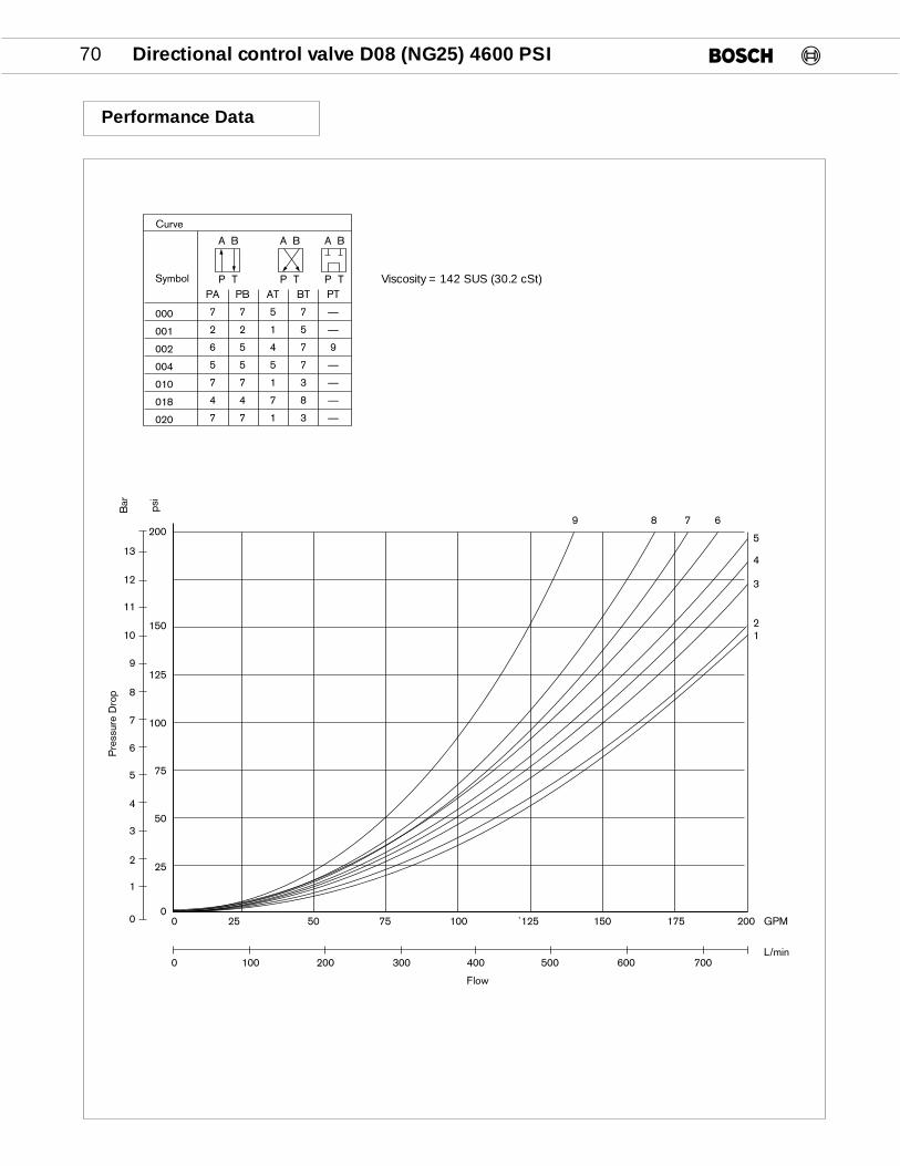
70 Directional control valve D08 (NG25) 4600 PSI
Performance Data
Viscosity = 142 SUS (30.2 cSt)
A B
P T
A B
P T
A B
P TSymbol
000
001
002
004
010
018
020
PA
7
2
6
5
7
4
7
PB
7
2
5
5
7
4
7
AT
5
1
4
5
1
7
1
BT
7
5
7
7
3
8
3
PT
—
—
9
—
—
—
—
Curve
150
125
100
75
50
25
00 25 50 75 100 `125 150 175
9
8
7
6
5
4
3
2
1
0
0 100 300 400 500L/min
Flow
Pre
ssur
e D
rop
Bar psi
200 GPM
200
10
11
12
13
200 600 700
9 8 7 6
5
4
3
21

Directional control valve D08 (NG25) 4600 PSI 71
1 2
Sol A Sol B
X YP T1 2
43
A B
3 AND 4 ARE EXTERNAL OF THE VALVE
Pilot & Drain Options
Fixed Pilot Chokes
Pilot valve
Fixedpilot choke
Main valve
PY – INT. PILOT, EXT. DRAIN; PLUG PORTS 2 & 3PT – INT. PILOT, INT. DRAIN; PLUG PORTS 3 & 4XY – EXT. PILOT, EXT. DRAIN; PLUG PORTS 1 & 2XT – EXT. PILOT, INT. DRAIN; PLUG PORTS 1 & 4XY – HYDRAULIC PILOT; PLUG PORTS 1 & 2
Plug Part No.
1 9 534 230 0021/4” BSPP 7
2 1 813 400 017M6 DIN 906 3
Orifice Diameter Part Number
0.030 (0.8mm) 9 533 230 385
0.040 (1mm) 9 533 230 382
0.050 (1.2mm) 9 533 230 383
0.060 (2mm) 9 533 230 384
Max. Pressure in P or X: 3625 psi (250 bar)
Max. Pressure in T or Y:3045 psi (210 bar) for type 3 control 3625 psi (250 bar) for type 2 control 1450 psi (100 bar) when using
flame proof solenoid
Pilot oil supply and drain is either exter-nal via the x and y ports or internal viathe P and T ports. Conversion is possi-ble by removing or installing plugs. Plugno. 1 is accessible from the bottom ofthe main valve. The pilot valve must beremoved to gain access to plug No. 2.When using internal pilot and drain, theX and Y ports in the subplate must beplugged.
A fixed pilot choke is an orifice placed inthe pilot line to increase the spool shifttime. Metering notches on the spool arestandard and by increasing the shifttime of the spool, the flow paths areopened and closed more graduallywhich reduces system shock. Fixed pilot
chokes can be added to a standardvalve at any time by simply removing thepilot valve and inserting the choke in theP port. The flange machined on thechoke holds it captive in the counter-bore for the O-ring. The chokes can beinserted in any of the ports of the pilot
valve depending on the desired result.Then a valve is ordered with a fixed pilotchoke the 0.040” (lmm) diameter orificeis installed in the P port. Chokes withother size orifice are available and are list-ed below.

72 Directional control valve D08 (NG25) 4600 PSI
Adjustable Pilot Chokes
TB A
A BX
Pmax. 5000 psi
RACINE, WI U.S.A.
BA
TP
883
1.57(40.0)180°PILOT CHOKE
ADJUSTING SCREW(BOTH ENDS)
6mm
SEAL PLATE1 811 037 800
P T
SOL BSOL A
A B
X Y
TP
P T
SOL BSOL A
A B
X Y
TP
For Conversion
Description Part number
NG6 Flow control module w/seal plate (meter out) 9 810 161 089
Seal plate 1 811 037 089
4 x M 5 x 70, DIN 912 – 10.9 (Part number is for one bolt) 2 910 151 180
METER-OUT(STANDARD)
METER-IN(TURN MODULAR VALVE 180º)
Adjustable chokes consist of a modularflow control valve which contains twonon-pressure compensated throttlevalves with free flow checks. It providesindependent control of the spool shifttime in both directions. Because the portpattern is symmetrical and a seal plate isused, the module can be turned 180° toprovide either meter-in or meter-out con-trol.
Meter-out is standard. If meter-in is need-ed, the pilot valve must be removed andthe flow control module rotated 180° onits longitudinal axis. The locating pin inthe bottom mounting surface of the flowcontrol module must be removed andinstalled on the opposite side beforereassembly. The seal plate alwaysremains on top of the main valve body.Torque value for the mounting bolts ofthe pilot valve is 5.0 lb/ft (7.0 Nm).
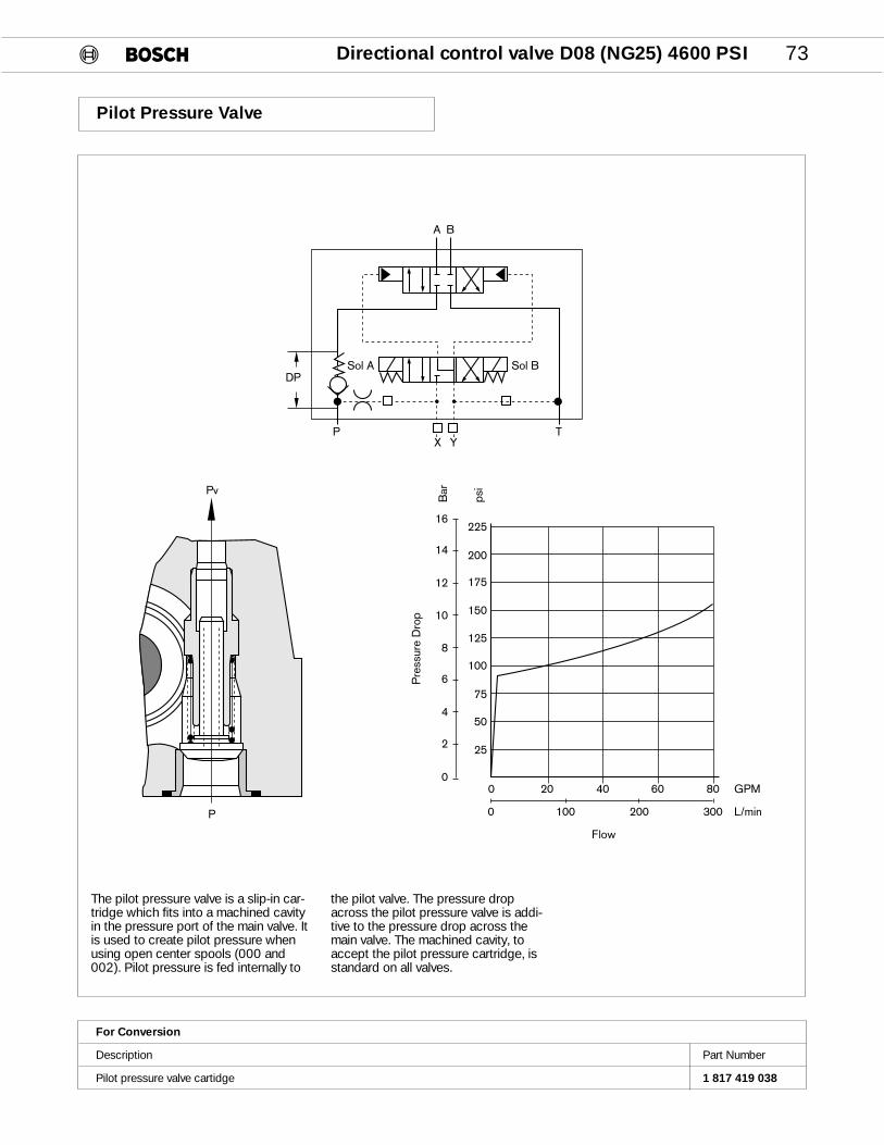
Directional control valve D08 (NG25) 4600 PSI 73
Pilot Pressure Valve
0 100 200 300 L/min
GPM806040200
Flow
225
200
175
150
125
100
75
50
25
0
2
4
6
8
10
12
14
16
Bar
psi
Pre
ssur
e D
rop
Pv
Sol A Sol B
X YP T
DP
A B
P
For Conversion
Description Part Number
Pilot pressure valve cartidge 1 817 419 038
The pilot pressure valve is a slip-in car-tridge which fits into a machined cavityin the pressure port of the main valve. Itis used to create pilot pressure whenusing open center spools (000 and002). Pilot pressure is fed internally to
the pilot valve. The pressure dropacross the pilot pressure valve is addi-tive to the pressure drop across themain valve. The machined cavity, toaccept the pilot pressure cartridge, isstandard on all valves.
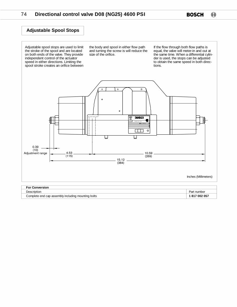
74 Directional control valve D08 (NG25) 4600 PSI
10.59(269)
15.12(384)
4.53(115)
0.39(10)
Adjustment range
A BX
Pmax. 5000 psi
RACINE, WI U.S.A.
BA
TP
883
Adjustable Spool Stops
Inches (Millimeters)
For ConversionDescription Part numberComplete end cap assembly including mounting bolts 1 817 002 057
Adjustable spool stops are used to limitthe stroke of the spool and are locatedon both ends of the valve. They provideindependent control of the actuatorspeed in either directions. Limiting thespool stroke creates an orifice between
the body and spool in either flow pathand turning the screw is will reduce thesize of the orifice.
If the flow through both flow paths isequal, the valve will meter-in and out atthe same time. When a differential cylin-der is used, the stops can be adjustedto obtain the same speed in both direc-tions.

Directional control valve D08 (NG25) 4600 PSI 75
Valve With AC/DC Solenoid And Wiring
TB A
A BX
Pmax. 5000 psi
RACINE, WI U.S.A.
BA
TP
883
2x 15 x 2.54x 28 x 3
4.92(125)
7.48(190)12.00
(305)
0.71(18)
1.69(43)
3.63(92.1) 4.58
(116.4)
Name Tagdescribespilot valve.
8.66(220)
5.63(143.1)
7.82(198.7)
2.63(66.9)
Name Tagdescribesmain valve.
1/2 - 13 x 2.5" long = 70 lb/ft (95Nm)
Name Tag describescomplete valve.
6x
7.74(196.5)
3.46(88)
Inches (Millimeters)
Valve With AC Solenoid (DIN)
AB T
X BA
RACINE, WI U.S.A.
Pmax. 5000 psi
883
P T
A B
2x 15 x 2.54x 28 x 31/2 - 13 x 2.5" long = 70 lb/ft (95Nm)
4.92(125)
7.48(190)12.00
(305)
0.71(18)
1.69(43)
Name Tag describescomplete valve.
3.63(92.1) 4.58
(116.4)
3.46(88)
Name Tagdescribespilot valve.
8.62(219)
5.63(143.1)
7.82(198.7)
2.63(66.9)
.47 (12.0)
Name Tagdescribesmain valve.
6x
Inches (Millimeters)
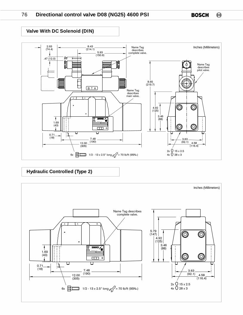
76 Directional control valve D08 (NG25) 4600 PSI
Valve With DC Solenoid (DIN)
TB A
A BX
Pmax. 5000 psi
RACINE, WI U.S.A.
BA
TP
883
2x 15 x 2.54x 28 x 3
4.92(125)
7.48(190)12.00
(305)
0.71(18)
1.69(43)
3.63(92.1) 4.58
(116.4)
Name Tagdescribespilot valve.
8.65(219.7)
5.93(150.6)
8.43(214.1)
2.93(74.4)
Name Tagdescribesmain valve.
3.46(88)
Name Tagdescribes
complete valve.
.47 (12.0)
1/2 - 13 x 2.5" long = 70 lb/ft (95Nm)6x
Inches (Millimeters)
Hydraulic Controlled (Type 2)
A BX
Pmax. 5000 psi
RACINE, WI U.S.A.
BA
TP
883
2x 15 x 2.54x 28 x 3
5.79(147)
4.92(125)
7.48(190)12.00
(305)
0.71(18)
1.69(43)
Name Tag describescomplete valve.
3.63(92.1) 4.58
(116.4)
3.46(88)
1/2 - 13 x 2.5" long = 70 lb/ft (95Nm)6x
Inches (Millimeters)

Directional control valve D08 (NG25) 4600 PSI 77
Subplates, Bottom Ported
C
X
A
T
B
P
Y
5.125(130.2)
3.969(100.8)
3.719(94.5)
3.031(76.9)
2.094(53.2)
1.156(29.4)
4 HOLES.5625 DRILL THRU
3.625(92.1)
1.815(46.1)
.688(17.5)
1.183(30.0)
.75(19.0)
.188(4.8)
2.938(74.6)
4.5(114.3)
6.0(152.4)
6 HOLES1/2-13 UNC-2B THD
.94 ±.03 DEEP
7.680(195.1)
4.902(124.5)
1.805(45.8)
.530(13.5)
3.0(76.2)
.75(19.0)
1.371(34.8)
2.558(64.9)
3.496(88.8)
5.240(133.1)
6.178(156.9)
7.368(187.1)
1.938(49.2)
3.0(76.2)
1.628(41.3)
4.058(103.1)
4.368(110.9)
8.74(22.2)
0.224(5.7)
C port is used for Inches (Millimeters)load sensing when using proportional valves.
When a subplate is not used, a machined pad must be providedfor mounting which is flat to within 0.004 in./in. and has a surface finish of 63 RMS.
P,T,A,B, X,Y,C, Maximum Pressure Weight Part Number1” NPTF 1/4” NPTF 5000 psi 25 lbs. 9 000 010 2161 1/4” NPTF (350 bar) (11.3 kg) 9 000 010 2171 1/2” NPTF 9 000 010 218#16 SAE #6 SAE 9 000 010 219#20 SAE 9 000 010 220#24 SAE 9 000 010 221 Bolt kit B-228 (Valve only) 6 x 1/2 – 13 x 2.5” Long 953 723

78 Directional control valve D10 (NG32) 3000 PSI
Features and Benefits
n Retained guide tube for easy replacement of coils
n Solenoid identification per U.S. standard. P➝A when solenoid “A” is energized
n Optional manual overrides available
n Certified Pilot Valve – Main section certification pending
n Dual frequency solenoids (50 or 60 Hertz)
n Throttling spools are available
n Optional load check
®

Directional control valve D10 (NG32) 3000 PSI 79
Order Code
This order code describes the desired model variances of the D10 (NG 32) directional control valves. Standard models are assigned a 10-digit number. See page 80.
SIZE32 - D10 (NG32)
SEALSV – VITON STD.
CONTROL TYPE
2 – HYDRAULIC
3 – ELECTRICAL
SPOOL CODE
REFER TO SPOOL CHART ON PAGE 80.
PILOT CHOKES*
F – FIXED
T – ADJUSTABLE
R – LOAD CHECK IN “P” PORT*
H – ADJUSTABLE SPOOL STOPS*
PILOT AND DRAINXY – EXT. PILOT EXT. DRAINPT – INT. PILOT INT. DRAINPY – INT. PILOT EXT. DRAINXT – EXT. PILOT INT. DRAIN
ELECTRICAL CONNECTIONSWS – DIN 43650/ISO4400 KL – WIRING BOX + SENT. LIGHTSKA – WIRING BOXKD – WIRING BOX + QUICK CONN.
(ANSI B93.55m – 1981 3 PIN SINGLE SOL. & 5 PIN. DOUBLE. SOL.)
KE – WIRING BOX + QUICK CONN. + SENT. LIGHTS
KG – WIRING BOX + QUICK CONN. (SINGLE SOL. 5 PIN)
KM – WIRING BOX + QUICK CONN. + SENT. LIGHTS (SINGLE SOL. 5 PIN)
EX – FLAME PROOF SOLENOID
0 8 1 W V 3 2 P 1 V 3 D 5 1 / 5 5 /
SOLENOID VOLTAGES
AC DC
115/60 012/00230/60 024/00Series “D” Dual Frequency
09 – MANUAL PUSH PINWITH RUBBER COVER*
55 – LOW PRESSUREVERSION
51 – SOLENOID IDENTIFICATIONPER U.S. STANDARD P›A WHEN SOLENOID “A” IS ENERGIZED (ANSI B93.9)
D – DESIGN SERIESD – STD**E – 24VDC LEAD WIRE COIL
SOLENOID OPTIONS*
C – COVERED PUSH PIN
** QUICK CONNECT FOR ESERIES IS MINI CONNECTOR(See PG 89)
Product Literature Disclaimer
SPECIFICATIONS AND/OR DIMENSIONS ARE SUBJECT TO CHANGE WITHOUT PRIOR NOTICE. PLEASE CONSULT FACTORY.
* If these options are not needed, omit them from the code

80 Directional control valve D10 (NG32) 3000 PSI
Part Numbers
KA KD KE KG KL KM WS WS
SPOOL SYMBOLS TRANSITION PILOT 110/115 110/115 110/115 110/115 110/115 110/115 110/115 24 VDC.NO. & DRAIN
000 XY Z529
PT Z505 Z538 Z530001 XY Z508 Z536
XT Z509
PY Z510002 XY Z513
XT Z512
PT Z516 Z527 Z531004 PY Z515
009 XY Z528
PT Z517 Z532010 XY Z518
018 PT Z520
PT Z523020 PY Z522
026 PT Z524
042 PT Z525
P T
A B
P T
A B
P T
A B
Standard valves are assigned a 10-digit part number. Describe unassigned valve combinations with the alpha-numeric order code.
9 810 234Z…
KA –WIRING BOXKD –WIRING BOX + QUICK CONNECT (3 PIN SINGLE &
5 PIN DOUBLE SOLENOID)KE –WIRING BOX + QUICK CONNECT + SENTINEL LIGHTSKG –WIRING BOX + QUICK CONNECT (SINGLE SOLENOID 5 PIN)KL – WIRING BOX + SENTINEL LIGHTSKM – WIRING BOX + QUICK CONNECT + SENTINEL LIGHTS
(SINGLE SOL. 5 PIN)WS –PLUG CONNECTER (DIN 43650 / ISO 4400)
P T
A B
P T
A B
P T
A B
P T
A B
P T
A B
P T
A B
P T
A B
P – INT.PILOT
X – EXT.PILOT
T – INT.DRAIN
Y – EXT.DRAIN

Directional control valve D10 (NG32) 3000 PSI 81
Specifications
General
Design Spool valve
Mounting type Subplate, D10 (NG 32)
Mounting Position as desired (Horizontal only for detented valves)
Ambient temperature –4 to 120°F (-20 to 50°C)
Seals Viton
CSA Certified File Number LR 93267-1 (Except flame proof solenoids)
Weights
Hydraulic 83.2 lbs. (37.8 kg)
Electrical 1 Solenoid 98 lbs. (44.5 kg)
Electrical 2 Solenoid 99 lbs. (44.9 kg)
Adjustable Pilot Chokes 4.4 lbs. (2 kg)
Hydraulic
Fluid Petroleum hydraulic fluids and most fire resistant fluids
Viscosity 60 – 2300 SUS (10 – 500 cSt)
Fluid temperature –4 to 175°F (–20 to 80°C)
Filtration Contamination class 19/16, according to ISO 4406 to be realized with filter ß25=75
Direction of flow As shown on symbol
Operating pressure Port P, A, B,T: 3000 PSI (210 bar) max.Port T: 1500 PSI (100 bar) max. w/flame proof solenoids
Pilot pressure 75 PSI (5.2 bar)min. 3000 PSI (210 bar) max.
Maximum flow 175 GPM (660 L/min) see ∆ P/Q curve page 82
Control volume 3.04 in3 (50 cm3) for 3 position valves
Electric
Duty factor 100%
Solenoid identification Meets ANSI/B93.9 - 1969 (R 1988) Standards* P › A when Sol. “A” is energized.
Enclosure type *IP 65 to IEC and DIN 40 050 (DIN Connectors)
Insulation class C VDE § 5
Voltage and frequency See table on page 88AC-solenoids 230/60 can be used with 220/50 and 115/60 can be used with 110/50 voltage supply
Voltage tolerance Nominal Voltage ±10%
Power ratingDC In Rush: 42WAC In Rush: ~ 3.5A Holding: ~ 1.14A
Response time 50 – 110ms Dependent on control pressure and spool
Switching frequency max. 1800/h
*Note: IP 65Protected against low pressure water jets from all direction
Dust tight
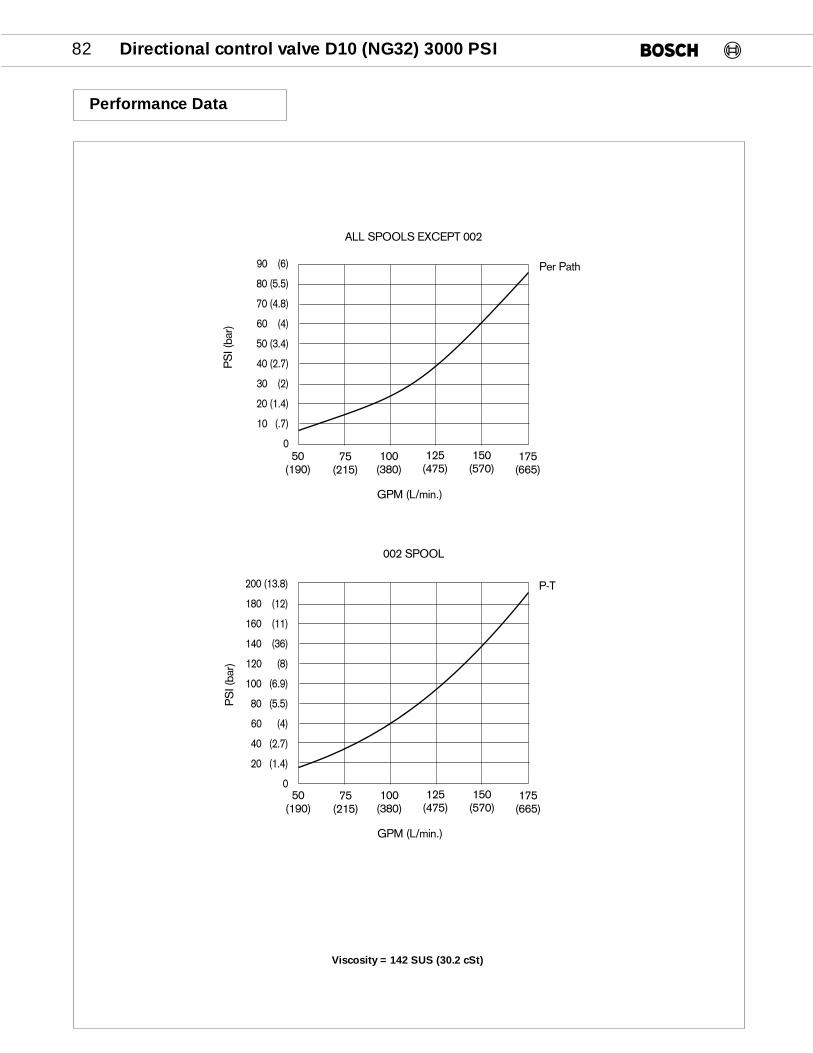
82 Directional control valve D10 (NG32) 3000 PSI
Performance Data
50(190)
75(215)
100(380)
125(475)
150(570)
GPM (L/min.)
PS
I (ba
r)ALL SPOOLS EXCEPT 002
175(665)
90 (6)
80 (5.5)
70 (4.8)
60 (4)
50 (3.4)
40 (2.7)
30 (2)
20 (1.4)
10 (.7)
0
50(190)
75(215)
100(380)
125(475)
150(570)
GPM (L/min.)
PS
I (ba
r)
002 SPOOL
175(665)
200 (13.8)
180 (12)
160 (11)
140 (36)
120 (8)
100 (6.9)
80 (5.5)
60 (4)
40 (2.7)
20 (1.4)
0
Per Path
P-T
Viscosity = 142 SUS (30.2 cSt)

Directional control valve D10 (NG32) 3000 PSI 83
Pilot & Drain Options
D (PLUG FOR EXTERNAL DRIAN)2(PLUG FOR EXTERNAL PILOT)1
P PILOT PORT
TANK
CYLINDER A
CYLINDER B
PRESSURE
2
A-ORIFICE PLUG(OPTIONAL)
ORIFICE PLUG(OPTIONAL)
P
(PLUG FOR INTERNAL PILOT)D DRAIN PORT1(PLUG FOR INTERNAL DRAIN)
PY – INT. PILOT, EXT. DRAIN; PLUG PORTS P2 & D2PT – INT. PILOT, INT. DRAIN; PLUG PORTS P2 & D1XY – EXT. PILOT, EXT. DRAIN; PLUG PORTS P1 &
D2
Pilot oil supply and drain are eitherexternal via the X and Y ports or inter-nal via the P and T ports. The P1 andD2 ports are 1/8" NPT).
The installations of the plugs deter-mines the source of the pilot oil andwhere it drains. Valves can be convert-ed in the field.
Adjustable Choke Option
5.54(140.7)
1.58(40.3)

84 Directional control valve D10 (NG32) 3000 PSI
Valve With AC/DC Solenoid & Wiring
T A P B T
5.29(134.4)
5.54(140.7)
10.15(257.8)
B(B)
9.00(228.6)
8.11(206.0)
.47(11.9)
A(A) 7.75
(196.8)
6.25(158.8)
.75(19.1)
2.11(53.6)
4.25 (108.0) REQ'D. TO REMOVE SOLENOID TYP. BOTH ENDS
Inches (Millimeters)
Valve With AC Solenoid (DIN)
10.98(278.9)
9.91(251.7)
7.07(179.6)
5.29(134.4)
5.54(140.7)
2.48(63.0)
.42(10.7)
1.54(39.1)
.79(20.1)
SEAL PLATE & SEALS SUPPLIED
2 LOCATING PINS, 0.25 (6.3)SEE SUB-PLATE DETAIL FOR LOCATION
8.11(206.0)
7.75(196.8)
3.87(98.3)
2.72(69.1)
1.35(34.3)
.18(4.6)
.16(4.1)
4.25 (108.0) REQ'D. TO REMOVE SOLENOID TYP. BOTH ENDS
B(B)
9.00(228.6)
4.25(108.0) A
(A)
1.69(42.9)
.75(19.1)
2.11(53.6)
CYLINDER GAGESCONNECTIONS1/4 NPTF
Inches (Millimeters)

Directional control valve D10 (NG32) 3000 PSI 85
Valve With DC Solenoid (DIN)
T A P B T
5.29(134.4)
5.54(140.7)
10.18(258.6)
B(B)
9.00(228.6)
9.20(233.7)
A(A) 7.75
(196.8)
6.25(158.8)
.75(19.1)
3.19(81.0)
4.25 (108.0) REQ'D. TO REMOVE SOLENOID TYP. BOTH ENDS
Inches (Millimeters)
Hydraulically Controlled (Type 2)
6.83(173.5)
6.08(154.4)
7.55(191.8)
3.47(88.1)
1/4" NPTFPILOT PORT 'Y'
3.20(81.3)
1/4" NPTFPILOT PORT 'X'
Inches (Millimeters)

MODEL NO. A B C D E F G H J K L M N
950917 Bottom 6.625 4.500 1.625 4.875 1.375 1.625 3.250 5.812 1.375 4.875 1.750(168.27) (114.30) (41.27) (123.82) (34.92) (41.27) (82.55) (147.64) (34.92) (123.82) (44.45) 1/4" NPTF 1-14" NPT
950919 Bottom 6.625 4.500 1.625 4.875 1.375 1.625 3.250 5.812 1.375 4.875 1.750(168.27) (114.30) (41.27) (123.82) (34.92) (41.27) (82.55) (147.64) (34.92) (123.82) (44.45) 1/4" NPTF 1-1/2" NPT
950920 Top 6.625 4.5 1.625 4.875 1.375 1.625 3.250 5.182 1.375 4.875 2.125(168.27) (114.30) (41.27) (123.82) (34.92) (41.27) (82.55) (147.64) (34.92) (123.82) (53.97)
Bottom 7.000 5.125 1.062 4.500 0.937 0.625 2.687 6.312 1.562 5.125 2.125 3/8" NPT 2" NPT(177.80) (130.17) (26.99) (114.3) (23.81) (15.87) (68.26) (160.34) (39.69) (130.17) (53.97)
86 Directional control valve D10 (NG32) 3000 PSI
Subplates, Bottom Ported
Inches (Millimeters)
����
����
0.750(19.05)
1.125(28.57)
6.250(158.75)
1.500(38.10)
1.625(41.27)
0.687(17.46)
G
E E
F
C
L
B
A
D
K4.500
(114.30)
CYLINDER B-N
CYLINDER A-NTOP BOTTOM
TANK - N
7.75(196.8)
4.500(114.30)
3.000(76.20)
5.812(147.62)
10.50(266.7)
H
PILOT PRESSURE - M
PILOT DRAIN - M
PRESSURE - N
2 HOLES FORLOCATING PINS
6 VALVE MTG. HOLES3/4-10 THD., 1.312(33.34) DEEP
4 HOLES 0.656 (16.67) DIA. THRU
7.500(190.50)
12.00(304.8)

AC
AC
AC
DC
DC
DC
Directional control valve accessories 87
D03 (NG6) D05 (NG10) D07 (NG16) D08 (NG25) D10 (NG32)
9 000 010 148 - - -
9 000 010 146 - - -
9 000 010 139 9 000 010 172 - -
- 9 000 010 181 9 000 010 201 -
- - 9 000 101 202 9 000 010 216
- - - 9 000 010 217 950 917
- - - 9 000 010 218 950 919
950 920
9 000 010 144 - - -
9 000 010 140 9 000 010 174 - -
- 9 000 010 183 9 000 010 203 -
- - 9 000 010 204 9 000 010 219
- - - 9 000 010 220
- - - 9 000 010 221
9 000 010 147
9 000 010 145
9 000 010 142 9 000 010 164
9 000 010 166
9 000 010 143
9 000 010 141 9 000 010 165
9 000 010 175
Accessories
Sentinel light assembly
Port “A”
Port “B”
Double
Port “A”
Port “B”
Double
D03 (NG6)
9 537 230 017
9 537 230 018
9 537 230 016
9 537 230 070
9 537 230 071
9 537 230 069
9 810 231 490
D05 (NG10)
9 537 230 003
9 537 230 004
9 537 230 002
9 537 230 076
9 537 230 077
9 537 230 075
9 810 232 499
Quick connect
Wiring Box Kit
Quick Connect female plugw/3 ft. pigtail for flexible con-duit
Quick Connect male plugfor wiring box
Quick Connect male plugfor wiring box
Plug connector, Standard
Plug connector withLED indicator lamp12 - 28 VDC
Rectifier Plug
Single Sol. AC
Double Sol. AC
Single Sol. AC
Double Sol. AC
Single Sol. DC
Double Sol. DC
1 834 484 134
Grey (A)
Black (B)
Grey (A)
Black (B)
951 901
951 902
778 345
778 346
9 536 230 040
1 834 484 058
1 834 484 057
1 834 484 136
1 834 484 137
Subplates
1.4 NPT
3/8 NPT
1/2 NPT
3/4” NPTF
1” NPTF
1 1/4” NPTF
1 1/2” NPTF
2" NPTF
#6 SAE
#8 SAE
#12 SAE
#16 SAE
#20 SAE
#24 SAE
1/4 NPT
3/8 NPT
1/2 NPT
3/4 NPT
#6 SAE
#8 SAE
#12 SAE
NFPA T3.51M
BottomPorted
SidePorted

1.46(37.2)
.1.18(30)
0.94(24)
88 Directional control valve accessories
Throttle Screw For Soft Shift Adjustment
SEAL KITSSet of Seals (Viton)
BOLT KITS
Kit (valve only)
D08 (NG25)
9 810 235 601
953 723
D10 (NG32)
9 810 234 535
953 523
D05 (NG10)
9 810 232 520
953 675
D03 (NG6)
9 810 231 529
953 611
D07 (NG16)
9 810 234 100
953 726
D08 (NG25/55)
9 810 235 600
953 594
Throttle Screw for soft shift adjustment
Adjustable
Fixed
*A B
Adjustable
*A B
.024 (0.6mm)
.040 (1mm)
* For speed adjustment when spool is moving in reference to cylinder parts
Wt. Lbs (kg)
.001(0.005)
Part Number
1 817 001 005
1 817 011 094
1 817 001 095
1 817 001 085
1 817 001 086
Solenoid Nut
Standard With Rubber Cover Covered
D03 (NG6) 9 535 230 082
D05 (NG10) 1 833 343 001
D03 (NG6) 1 833 343 015
D05 (NG10) 1 833 343 003
D03 (NG6) 1 833 343 013
D05 (NG10) 1 833 343 002
Solenoid Coil
Voltage/Frequency
115/60 (Dual Frequency)
230/60 (Dual Frequency)
12VDC
24VDC
96VDC
125VDC
240VDC
Flying Leads Din 43650
D03 (NG6)
9 536 230 015
9 536 230 016
1 837 001 292
1 837 001 293
N/A
N/A
9 536 230 059
D05 (NG10)
9 536 230 004
9 536 230 005
1 837 001 296
1 837 001 297
N/A
9 536 230 056
9 536 230 057
D03 (NG6)
1 837 001 255
1 837 001 256
1 837 001 226
1 837 001 227
1 837 001 232
N/A
N/A
D05 (NG10)
1 837 001 212
1 837 001 213
1 837 001 139
1 837 001 140
1 837 001 159
N/A
N/A
Inches (Milimeters)

Directional control valve accessories 89
The quick connect male plug is a standardthree or five pole electrical connector with3.25” leads except the ground lead which is4”. All valves ordered with a quick connect arewired to an industry standard (NFPA Standard13.5.29M) which is shown below. The wiringbox has a 1/2” NPT electrical connection oneach end in which the quick connect can beinstalled. On single solenoid valves, the quick
connect will be located above the solenoid.On double solenoid valves, it is located on theB port end of the valve. The five pin connectorfor a single solenoid valve is offered for con-sumers that use both single and double sole-noid valves but want to standardize on onefemale quick connect plug.
Quick Connect Male Plug
AC Solenoids
DC SolenoidsInches (Milimeters)
Inches (Milimeters)
1
32
1
32
4
5 1
32
4
5
1.00 (25.4) Hex.
3 – Lead (To Solenoid)
2 – Lead (To Solenoid)
2 – Lead (To Sol. “A”)
1 – Green Lead (Ground)
5 – Lead (To Sol. “B”)
4 – Lead (To Sol. “A”)
3 – Green Lead (Ground)
1 – Lead (To Sol. “B”) 1 – Lead (To Solenoid)2 – Lead (Capped)
5 – Lead (To Solenoid)
4 – Lead (Capped)
3 – Green Lead (Ground)
CONNECTOR FOR SINGLE SOLENOID
FIVE PIN CONNECTORFOR DOUBLE SOLENOID
FIVE PIN CONNECTOR FOR SINGLE SOLENOID
.38(9.6)
1/2 NPT
.47(11.9)
.469" .313".673
3" pigtails
1/2" NPT
1/2" - 14 NPT Receptacle
1
4
3
2
3
4
1
2
FACE OF MALE CONNECTORMOUNTED ON VALVE
FACE VIEW OF FEMALECONNECTOR
PIN #1 - + SOLENOID APIN #2 - VALVE GROUNDPIN #3 - COMMONPIN #4 - + SOLENOID B
NOTE: SINGLE SOLENOID VALVES WIRED ON SOLENOID ‘A’ PIN.

90 Directional control valve accessories
1.35 (34.2)
2.09 (53)
.22 (5.5)M3
1.08 (27.5)
0
20
40
60
80
100
20
40
60
80
200
20
40
20 40 60 80 100 20 40 60 80 200 20 40
UE [V~]
UA [V=]
=UA
190/0096/00
~UE
220/50110/50
VDR
Single
Double3 (76.2)
2-7/8 (70.6)
.35 (9)
.62(15.9)
.54(13.7)
Single
Double5 (127)
4 -1/2 (114.3)
1/2 (12.7)
Standard Plug &Plug With Lite
Inches (Millimeters)
PG 11
RectifierPlug
Wire lead length 3ft. ± 3 in.(.9m ± 7cm)
Sentinel Lite D03 (NG6)
Sentinel Lite D08 (NG10)
Female Plug AC
Quick Connect AC
Quick Connect DC

ROBERT BOSCH FLUID POWER CORPORATIONP.O. BOX 2025RACINE, WISCONSIN 53401-2025 U.S.A.Phone (414)554-7100, Fax (414)554-7117
PRINTED IN U.S.A.
9 535 233 717HPUS AKY 006/27 US (10.95)


