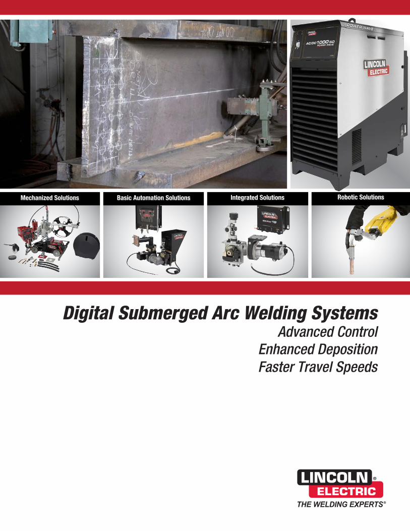
Digital Submerged Arc Welding SystemsAdvanced Control
Enhanced DepositionFaster Travel Speeds
Integrated Solutions Robotic SolutionsBasic Automation SolutionsMechanized Solutions

[ 2 ] | Submerged Arc Equipment Systems
THE LINCOLN ELECTRIC COMPANY
About The Lincoln Electric Company Submerged Arc Welding Platforms
Lincoln Electric is the world’s leading
manufacturer of welding equipment
and consumables. Our focus is
helping companies make their welding
operations more effective, more
efficient, and more profitable.
We are dedicated to two equally
important goals:
Exceptional quality and
exceptional service
Our field support team –– with
hundreds of field sales engineers and
thousands of knowledgeable and
responsive Lincoln Electric distributors
in countries all over the world –– is the
largest in the industry.
Innovative thinking
For a quality, service-first attitude;
innovative design, manufacturing, and
packaging; and worldwide strength —
Choose Lincoln Electric.
Lincoln Electric’s advanced submerged arc systems couple the industry’s most advanced power source with mobile, hard automation or robotic feeding equipment to achieve new levels of welding performance and operational efficiency.
Whether your application is bridge decking, pressure vessels, panel line, seamer, pipe mill integrator solutions or submerged arc robotic welding, the software-driven Power Wave® AC/DC 1000® SD and your choice of integrated feeding equipment can help your operations improve weld quality, reduce welding and operational costs and increase weld team productivity.
Advanced Control• Our Waveform Control Technology® allows operators to set
all AC and DC arc and PLC-based fixture motion control parameters from a single mountable or hand-held extended-range pendant. It is no longer necessary to reverse electrode and work cables.
Energy Savings• With input current requirements reduced by up to 50%
for our inverter-based system, customers consistently report significant energy savings over traditional submerged arc welding equipment.
Modular Components• Power Wave® and MAXsa® controller and feed
head components are engineered to readily adapt the system for use in almost any indoor or outdoor heavy wall thickness submerged arc welding application.
Rugged Reliability• Power source, controller and feed heads are reliability
tested to meet IP23 standards. Each is designed to withstand harsh environments and outdoor storage.
Lincoln Electric technical teams are standing by to assist you with set up, customized welding mode development optimized for your application, and welding consumables testing and selection.

Submerged Arc Equipment Systems | [ 3 ]
INTRODUCTION
Power SourcePower Wave® AC/DC 1000® SD . . . . . . 4-5
Mechanized SolutionPower Wave® AC/DC 1000® SD
Cruiser® Tractor . . . . . . . . . . . . . . . . . . . 6-7
Basic Automation SolutionPower Wave® AC/DC 1000® SD
MAXsa® 10 Controller . . . . . . . . . . . . . . 8-9
MAXsa® 22 Feed Head . . . . . . . . . . . 10-11
Integrated and Robotic SolutionsPower Wave® AC/DC 1000® SD
MAXsa® 19 Controller and MAXsa® 29 Feed Head . . . . . . . . 12-14
Modified Series Arc™ . . . . . . . . . . . . . . . 15
Robotic Submerged Arc Solutions . . . . . 16
Appendix . . . . . . . . . . . . . . . . . . . . . 17-27

[ 4 ] | Submerged Arc Equipment Systems
THE LINCOLN ELECTRIC COMPANY
Power Wave®
AC/DC 1000® SD
Increase Productivity, Quality and Flexibility
The Power Wave® AC/DC 1000® SD delivers Waveform Control Technology® to submerged arc welding. Choose constant current or constant voltage operation and set variable frequency and amplitude. Software-driven AC, DC positive or DC negative output allows the user to control the deposition rate and penetration. The result over conventional power sources is increased weld speeds, consistently higher quality welds and improved efficiencies in a single or multi-arc environment.
ProcessesDC+ Submerged ArcDC- Submerged ArcBalanced AC Submerged ArcVariable AC Submerged Arc
Output
Input
AC
DC
3PHASE
6050Hz
Product Name
Product Number
Input
Voltage
Rated Output
Current/Voltage/Duty Cycle
Input Current
@ Rated Output
Output Range
Dimensions H x W x D in . (mm)
Net Weight
lbs . (kg)
Power Wave® AC/DC 1000® SD
K2803-1(1)
380/400/460/500/
575/3/50/60
1000A/44V/100%
82/79/69/62/55
100-1000A
49.2 x 19.2 x 46.2
(1250 x 488 x 1174)
800
(363)
(1) Filter is required to meet CE conducted emission requirements. The K2444-3 must be used with the K2803-1.
Technical Specifications
www.lincolnelectric.com/green
COMMUNICATIONS PROTOCOL
Key Features
• 380 - 575 VAC, 50/60Hz Voltage Input – Offers the ability to be connected anywhere in the world.
• Voltage Compensation and Reliable Input Voltage Connection – Provides consistent operation over ± 10% input voltage variation.
• No Hardware Reconfiguration Required with Easy Polarity Switching – Eliminates downtime.
• Easy to Parallel Machines or Run Multiple Arcs .
• 3-Phase Voltage Input – Eliminates the imbalance associated with transformer-based AC welding machines.
• 95% Power Factor Correction – Enables connection of multiple machines on the same plant infrastructure for lower installation costs.
• Severe Duty – Can be stored outdoors. IP23 Rated.
• ArcLink®, Ethernet, and DeviceNet™ Communication – Offers remote process monitoring, control and troubleshooting.
• True Energy™ – Measures, calculates and displays instantaneous energy in the weld for critical heat input calculations.
• CheckPoint™ and Production Monitoring™ 2 .2 – Use your server or our cloud-based server to view or analyze your welding data on almost any device – desktop, laptop, iPhone® or iPad®, Blackberry® and others. Track equipment usage, store weld data, configure fault limits and more.
• Software Based Controls – Can be upgraded as new features become available.
• iARC™ Digital Control - 90 times faster than the previous generation, delivering a responsive arc.
• Factory Burn-In Tested – At maximum output for 2 hours to ensure quality and reliability.
Submerged Arc Equipment Systems | [ 5 ]
POWER SOURCE
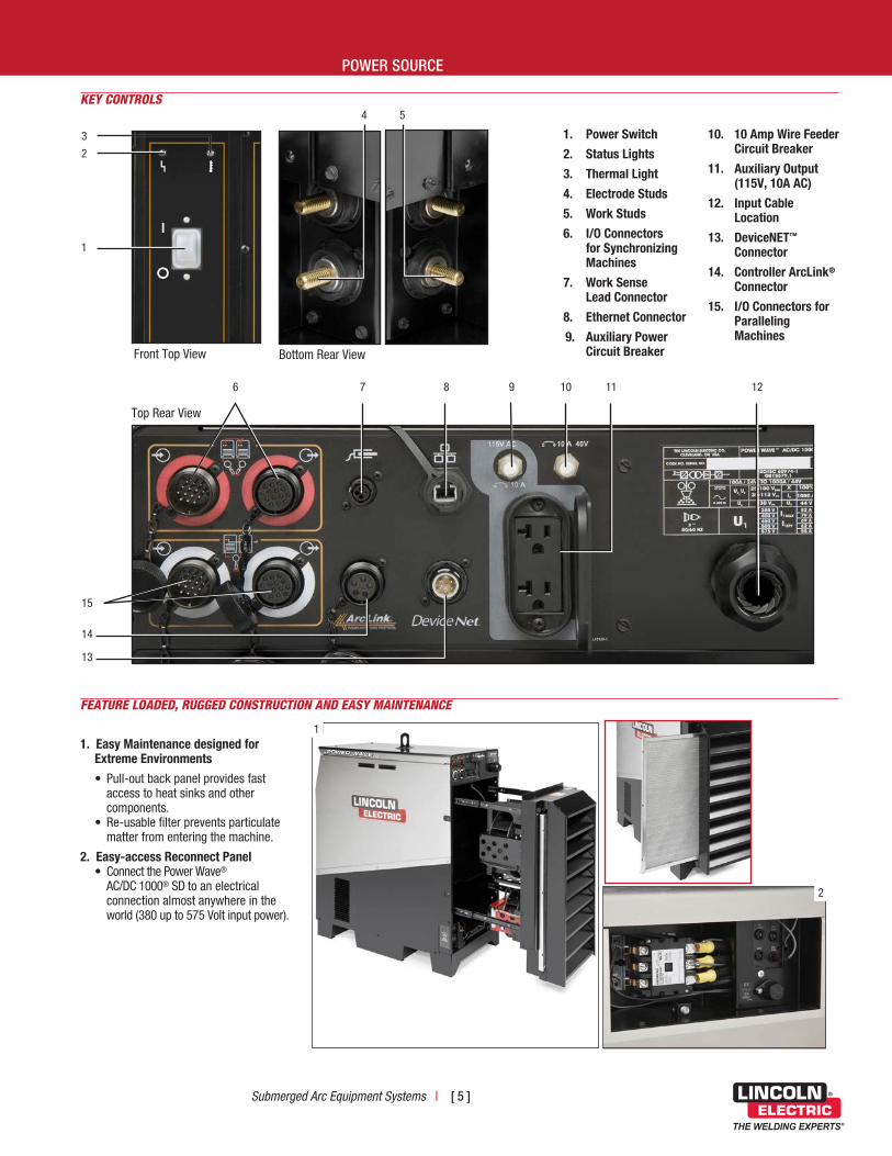
KEY CONTROLS
Front Top View
3
2
1
Bottom Rear View
4 5
6 7 8 9 10 11
15
14
13
Top Rear View
1 . Power Switch
2 . Status Lights
3 . Thermal Light
4 . Electrode Studs
5 . Work Studs
6 . I/O Connectors for Synchronizing Machines
7 . Work Sense Lead Connector
8 . Ethernet Connector
9 . Auxiliary Power Circuit Breaker
10 . 10 Amp Wire Feeder Circuit Breaker
11 . Auxiliary Output (115V, 10A AC)
12 . Input Cable Location
13 . DeviceNET™ Connector
14 . Controller ArcLink®
Connector
15 . I/O Connectors for Paralleling Machines
FEATURE LOADED, RUGGED CONSTRUCTION AND EASY MAINTENANCE
1 . Easy Maintenance designed for Extreme Environments
• Pull-out back panel provides fast access to heat sinks and other components. • Re-usable filter prevents particulate matter from entering the machine.
2 . Easy-access Reconnect Panel • Connect the Power Wave® AC/DC 1000® SD to an electrical connection almost anywhere in the world (380 up to 575 Volt input power).
11
2
12
[ 6 ] | Submerged Arc Equipment Systems
THE LINCOLN ELECTRIC COMPANY
Output
Input
40VDC
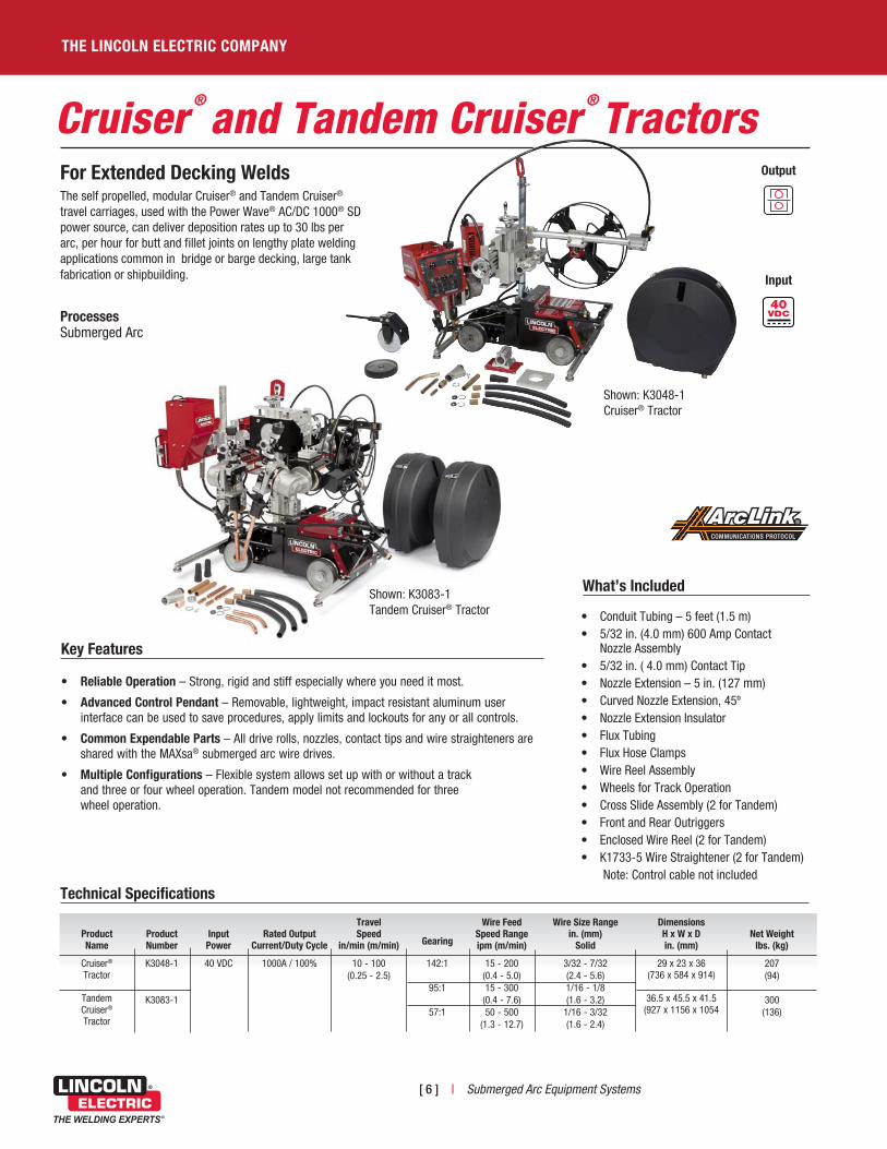
• Conduit Tubing – 5 feet (1.5 m)• 5/32 in. (4.0 mm) 600 Amp Contact Nozzle Assembly• 5/32 in. ( 4.0 mm) Contact Tip• Nozzle Extension – 5 in. (127 mm)• Curved Nozzle Extension, 45º• Nozzle Extension Insulator• Flux Tubing• Flux Hose Clamps• Wire Reel Assembly• Wheels for Track Operation• Cross Slide Assembly (2 for Tandem)• Front and Rear Outriggers• Enclosed Wire Reel (2 for Tandem)• K1733-5 Wire Straightener (2 for Tandem)
Note: Control cable not included
Technical Specifications
For Extended Decking WeldsThe self propelled, modular Cruiser® and Tandem Cruiser® travel carriages, used with the Power Wave® AC/DC 1000® SD power source, can deliver deposition rates up to 30 lbs per arc, per hour for butt and fillet joints on lengthy plate welding applications common in bridge or barge decking, large tank fabrication or shipbuilding.
ProcessesSubmerged Arc
What’s Included
Key Features
• Reliable Operation – Strong, rigid and stiff especially where you need it most.
• Advanced Control Pendant – Removable, lightweight, impact resistant aluminum user interface can be used to save procedures, apply limits and lockouts for any or all controls.
• Common Expendable Parts – All drive rolls, nozzles, contact tips and wire straighteners are shared with the MAXsa® submerged arc wire drives.
• Multiple Configurations – Flexible system allows set up with or without a track and three or four wheel operation. Tandem model not recommended for three wheel operation.
Cruiser®
and Tandem Cruiser®
Tractors
COMMUNICATIONS PROTOCOL
Product Name
Product Number
Input Power
Rated Output
Current/Duty Cycle
Travel Speed
in/min (m/min)
Gearing
Wire Feed Speed Range ipm (m/min)
Wire Size Range in . (mm)
Solid
Dimensions H x W x D in . (mm)
Net Weight
lbs . (kg)
Cruiser® Tractor
Tandem Cruiser® Tractor
K3048-1
K3083-1
40 VDC 1000A / 100% 10 - 100 (0.25 - 2.5)
142:1
95:1
57:1
15 - 200 (0.4 - 5.0)15 - 300
(0.4 - 7.6)50 - 500
(1.3 - 12.7)
3/32 - 7/32 (2.4 - 5.6)1/16 - 1/8(1.6 - 3.2)
1/16 - 3/32(1.6 - 2.4)
29 x 23 x 36 (736 x 584 x 914)
36.5 x 45.5 x 41.5(927 x 1156 x 1054
207(94)
300(136)
Shown: K3048-1 Cruiser® Tractor
Shown: K3083-1 Tandem Cruiser® Tractor
Submerged Arc Equipment Systems | [ 7 ]
MECHANIZED SOLUTION
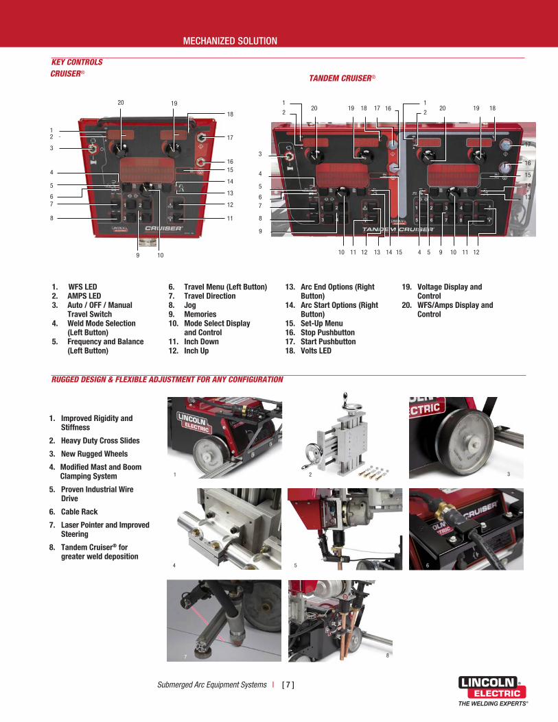
RUGGED DESIGN & FLEXIBLE ADJUSTMENT FOR ANY CONFIGURATION
KEY CONTROLS
2
3
4
5
8
67
9
11
12
13
14
1516
17
18
1920
10
1
CRUISER®
2 2
3
4
4
5
5
8
9
9 1010 11 13
13
1112 14 15
14
15
16
16
17
1718 181919 2020
12
67
1 1
TANDEM CRUISER®
1 . WFS LED2 . AMPS LED3 . Auto / OFF / Manual
Travel Switch4 . Weld Mode Selection
(Left Button)5 . Frequency and Balance
(Left Button)
6 . Travel Menu (Left Button)7 . Travel Direction8 . Jog9 . Memories10 . Mode Select Display
and Control11 . Inch Down12 . Inch Up
13 . Arc End Options (Right Button)
14 . Arc Start Options (Right Button)
15 . Set-Up Menu16 . Stop Pushbutton17 . Start Pushbutton18 . Volts LED
19 . Voltage Display and Control
20 . WFS/Amps Display and Control
3
6
7
54
2
8
1
1 . Improved Rigidity and Stiffness
2 . Heavy Duty Cross Slides
3 . New Rugged Wheels
4 . Modified Mast and Boom Clamping System
5 . Proven Industrial Wire Drive
6 . Cable Rack
7 . Laser Pointer and Improved Steering
8 . Tandem Cruiser® for greater weld deposition

[ 8 ] | Submerged Arc Equipment Systems
THE LINCOLN ELECTRIC COMPANY
ArcLink®-enabled Controller for Power Wave® AC/DC 1000® SD Systems
The MAXsa® 10 controller offers a single monitoring and control point for the entire hard automation welding system. Operators have full control over AC and DC welding parameters and easy PLC interfacing to control fixture travel, timers and other system commands.
ProcessesSubmerged Arc
Output
Input
Technical Specifications
Product Name
Product Number
Input Power
Dimensions H x W x D in . (mm)
Net
Weight lbs . (kg)
MAXsa® 10 Controller K2814-3 40 VDC 15 x 13 x 4 (381 x 259 x 102)
25 (11.3)
Key Features
• Severe Duty Ready – The controller is IP23 rated and ready for operation in harsh environments.
• Pendant Box – Mount the controller in the standard protective box or remove the pendant for hand-held operation. Extend hand-held operation from 4 feet (1.2 m) up to 100 feet (30.5 m) with an ArcLink® extension cable.
• Eight Procedure Memories – Pre-set and save your optimal welding parameters for repeating applications and recall later for fast changeovers.
• User-Friendly Controls – Clear digital display and controls make it easy to set weld modes, AC operation, strike/start/end options, travel stop/start, timers and other parameters.
• Limit Control – Apply operator procedure limits or lockout on any or all parameters.
• Waveform Control Technology® – Allows the user to choose from a library of pre-programmed weld modes. Parameters for each mode can be adjusted within a limited range to achieve optimal balance between deposition rate and penetration.
MAXsa®
10 Controller
COMMUNICATIONS PROTOCOL
Submerged Arc Equipment Systems | [ 9 ]
BASIC AUTOMATION SOLUTION
RUGGED DESIGN, FLEXIBLE CONNECTION
3
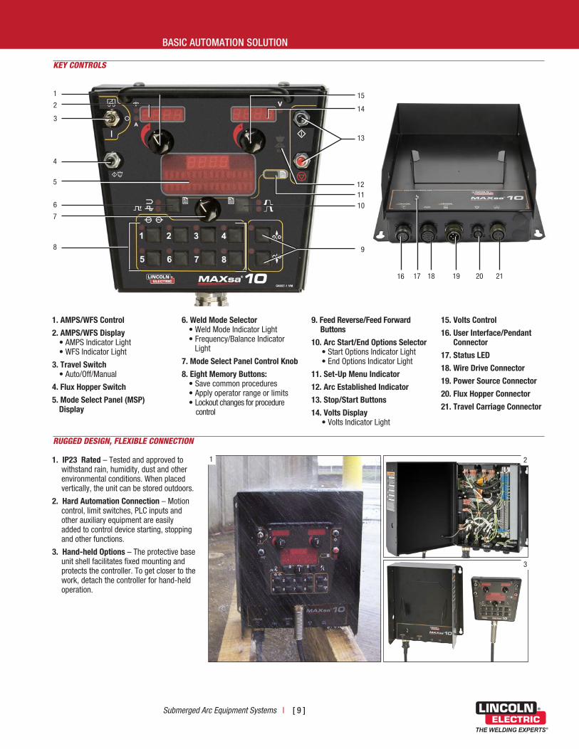
1 . AMPS/WFS Control
2 . AMPS/WFS Display • AMPS Indicator Light • WFS Indicator Light
3 . Travel Switch • Auto/Off/Manual
4 . Flux Hopper Switch
5 . Mode Select Panel (MSP) Display
6 . Weld Mode Selector • Weld Mode Indicator Light • Frequency/Balance Indicator Light
7 . Mode Select Panel Control Knob
8 . Eight Memory Buttons: • Save common procedures • Apply operator range or limits • Lockout changes for procedure control
9 . Feed Reverse/Feed Forward Buttons
10 . Arc Start/End Options Selector • Start Options Indicator Light • End Options Indicator Light
11 . Set-Up Menu Indicator
12 . Arc Established Indicator
13 . Stop/Start Buttons
14 . Volts Display • Volts Indicator Light
15 . Volts Control
16 . User Interface/Pendant Connector
17 . Status LED
18 . Wire Drive Connector
19 . Power Source Connector
20 . Flux Hopper Connector
21 . Travel Carriage Connector
1
KEY CONTROLS
2
6
4
5
9
7
8
10
11
13
14
15
1 . IP23 Rated – Tested and approved to withstand rain, humidity, dust and other environmental conditions. When placed vertically, the unit can be stored outdoors.
2 . Hard Automation Connection – Motion control, limit switches, PLC inputs and other auxiliary equipment are easily added to control device starting, stopping and other functions.
3 . Hand-held Options – The protective base unit shell facilitates fixed mounting and protects the controller. To get closer to the work, detach the controller for hand-held operation.
1
16 18 19 20 2117
2
3
12
[ 10 ] | Submerged Arc Equipment Systems
THE LINCOLN ELECTRIC COMPANY
MAXsa®
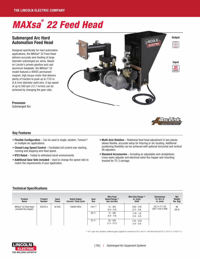
22 Feed HeadSubmerged Arc Hard Automation Feed Head
Designed specifically for hard automation applications, the MAXsa® 22 Feed Head delivers accurate wire feeding of large diameter submerged arc wires. Based on Lincoln’s proven gearbox and cast aluminum feedplate, the MAXsa® 22 model features a 40VDC permanent magnet, high torque motor that delivers plenty of traction to push up to 7/32 in. (5.6 mm) diameter solid wire. A top speed of up to 500 ipm (12.7 m/min) can be achieved by changing the gear ratio.
ProcessesSubmerged Arc
Output
Input
Technical Specifications
Product Name
Product Number
Input Power
Rated Output Current / Duty Cycle
Gear Box
Wire Feed
Speed Range (1) ipm (m/min)
Wire Size Range (1)
in . (mm) Solid
Dimensions H x W x D in . (mm)
Net
Weight lbs . (kg)
MAXsa® 22 Feed Head (includes flux hopper)
K2370-2 40 VDC 1000A/100% 142:1(1) 15 - 200 (0.4 - 5.0)
3/32- 7/32 (2.4 - 5.6)
23.5 x 17 x 20 (597 x 432 x 508)
80 (36.3)
95:1(1) 15 - 300 (0.4 - 7.6)
1/16 - 1/8(1.6 - 3.2)
57:1(1) 50 - 500 (1.3 - 12.7)
1/16 - 3/32(1.6 - 2.4)
(1) 142:1 gear set is standard. Additional gears supplied for conversion to 95:1 and 57:1 with Wire Drive (K2370-2, K2312-2, or K2311-1).
COMMUNICATIONS PROTOCOL
Key Features
• Flexible Configuration – Can be used in single, tandem, Twinarc® or multiple arc applications.
• Closed Loop Speed Control – Facilitates full control over starting, running and stopping wire feed speed.
• IP23 Rated – Tested to withstand harsh environments.
• Additional Gear Sets included – Used to change the speed ratio to match the requirements of your application.
• Multi-Axis Rotation – Rotational feed head adjustment in two planes allows flexible, accurate setup for fixturing or arc locating. Additional positioning flexibility can be achieved with optional horizontal and vertical lift adjusters.
• Standard Accessories – Including an adjustable wire straightener, cross-seam adjuster and electrical valve flux hopper and mounting bracket for TC-3 carriage.

Submerged Arc Equipment Systems | [ 11 ]
BASIC AUTOMATION SOLUTION
KEY CONTROLS
1 . Cross Seam Adjuster
2 . Wire Straightener
3 . Mounting Bracket
4 . Fuse
5 . 14-Pin Connector
6 . Lead (67)
7 . Motor
8 . Idle Roll Arm
9 . Tension Indicator
10 . Flux Hopper
11 . Flux Valve Connector
1 . Submerged Arc Contact Nozzle Assembly (K231-1) For 5/64 thru 3/16 in. (2.0 thru 4.8 mm) electrode at currents generally below 600 amps. Outer flux cone gives full flux coverage with minimum consumption. (Rated for up to 650 amps.)
2 . Positive Contact Assembly (K148A + K148B) For single arc welding at high currents.
3 . Contact Jaw Assembly (K226R) Single arc contact jaw assembly for 1/8 - 7/32 in. (3.2 - 5.6 mm) diameter wire. Maximum life at currents over 600 amps.
4 . ESO (Extended Stick-Out) Extension (K149-5/32) Linc-Fill long stickout extension for K148A Single Arc Positive Contact Nozzle Assembly. Required for long stickout technique.
5 . Narrow Gap Deep Groove Nozzle (K386) For single arc 3/32 in. (2.4 mm) diameter wire welding on thick walled steel plate with nearly parallel-sided, narrow gap joint preparations.
6 . Large Wire Twinarc® Contact Assemblies (K225) Feeds two 5/64 in. (2.0 mm), 3/32 in. (2.4 mm) or 1/8 in. (3.2 mm) wires for submerged arc welding on “Fast-Fill” joints or hardfacing beads.
7 . Tiny Twinarc® Contact Assemblies (K129-XX) Feeds two electrodes for high speed submerged arc welds. Includes contact nozzle, wire guides, drive rolls and guides, and a second wire reel and mounting bracket.
1
2
3
4
5
6
7
11 910 78 6
1 32 54
CONTACT NOZZLES (ONE REQUIRED)
OPTIONAL TC-3 TRAVEL CARRIAGE
TC-3 Travel Carriage The TC-3 travel carriage allows the mounting of up to two feed heads/ controllers and wire reels to a beam for basic hard automation installations.
Beam Profile Recommended for the TC-3 travel carriage. (See manual for more precise dimensions.)
8 in. (203 mm)10 in. (254 mm)12 in. (305 mm)
[ 12 ] | Submerged Arc Equipment Systems
THE LINCOLN ELECTRIC COMPANY
MAXsa®
19 and MAXsa
®
19 MSA ControllerSubmerged Arc Controllers forFabrication Integrators andRobotic Applications
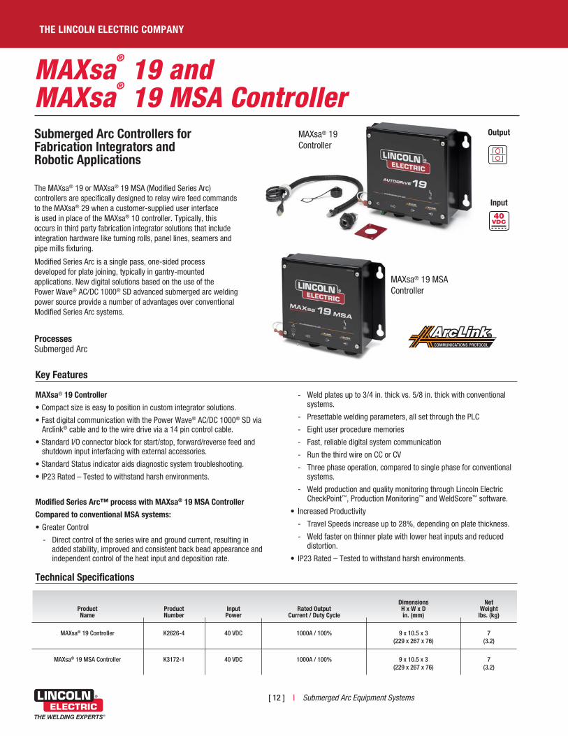
The MAXsa® 19 or MAXsa® 19 MSA (Modified Series Arc) controllers are specifically designed to relay wire feed commands to the MAXsa® 29 when a customer-supplied user interface is used in place of the MAXsa® 10 controller. Typically, this occurs in third party fabrication integrator solutions that include integration hardware like turning rolls, panel lines, seamers and pipe mills fixturing.
Modified Series Arc is a single pass, one-sided process developed for plate joining, typically in gantry-mounted applications. New digital solutions based on the use of the Power Wave® AC/DC 1000® SD advanced submerged arc welding power source provide a number of advantages over conventional Modified Series Arc systems.
Processes Submerged Arc
Output
Input
Technical Specifications
COMMUNICATIONS PROTOCOL
Key Features
MAXsa® 19 Controller
• Compact size is easy to position in custom integrator solutions.
• Fast digital communication with the Power Wave® AC/DC 1000® SD via Arclink® cable and to the wire drive via a 14 pin control cable.
• Standard I/O connector block for start/stop, forward/reverse feed and shutdown input interfacing with external accessories.
• Standard Status indicator aids diagnostic system troubleshooting.
• IP23 Rated – Tested to withstand harsh environments.
Modified Series Arc™ process with MAXsa® 19 MSA Controller
Compared to conventional MSA systems:
• Greater Control
- Direct control of the series wire and ground current, resulting in added stability, improved and consistent back bead appearance and independent control of the heat input and deposition rate.
- Weld plates up to 3/4 in. thick vs. 5/8 in. thick with conventional systems.
- Presettable welding parameters, all set through the PLC
- Eight user procedure memories
- Fast, reliable digital system communication
- Run the third wire on CC or CV
- Three phase operation, compared to single phase for conventional systems.
- Weld production and quality monitoring through Lincoln Electric CheckPoint™, Production Monitoring™ and WeldScore™ software.
• Increased Productivity
- Travel Speeds increase up to 28%, depending on plate thickness.
- Weld faster on thinner plate with lower heat inputs and reduced distortion.
• IP23 Rated – Tested to withstand harsh environments.
MAXsa® 19Controller
MAXsa® 19 MSAController
Product Name
Product Number
Input Power
Rated Output Current / Duty Cycle
Dimensions H x W x D in . (mm)
Net
Weight lbs . (kg)
MAXsa® 19 Controller
K2626-4
40 VDC
1000A / 100%
9 x 10.5 x 3
(229 x 267 x 76)
7
(3.2)
MAXsa® 19 MSA Controller
K3172-1
40 VDC
1000A / 100%
9 x 10.5 x 3
(229 x 267 x 76)
7
(3.2)
Submerged Arc Equipment Systems | [ 13 ]
INTEGRATED AND ROBOTIC SOLUTIONS
KEY CONTROLS
4
5
5
6
2
3 2
3
4
1
1
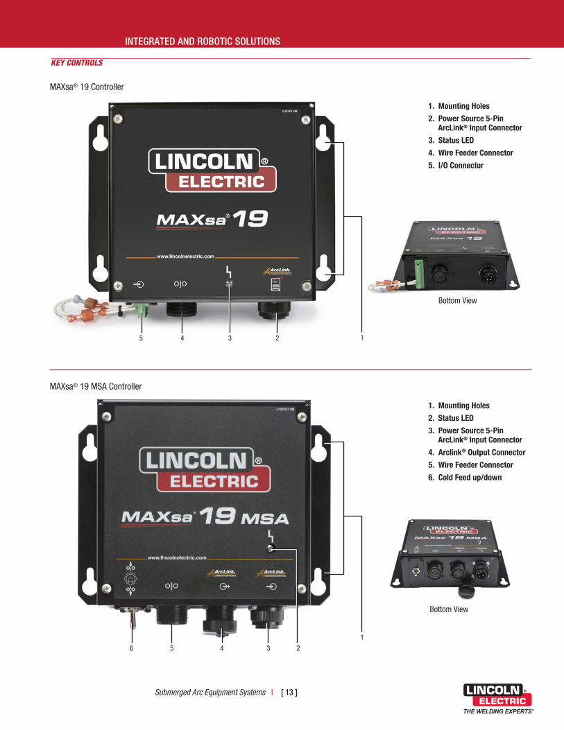
1 . Mounting Holes
2 . Power Source 5-Pin ArcLink® Input Connector
3 . Status LED
4 . Wire Feeder Connector
5 . I/O Connector
1 . Mounting Holes
2 . Status LED
3 . Power Source 5-Pin ArcLink® Input Connector
4 . Arclink® Output Connector
5 . Wire Feeder Connector
6 . Cold Feed up/down
MAXsa® 19 Controller
MAXsa® 19 MSA Controller
Bottom View
Bottom View

[ 14 ] | Submerged Arc Equipment Systems
THE LINCOLN ELECTRIC COMPANY
KEY CONTROLS
89 67 45
1
2
3
1 . Wire Straightener
2 . Mounting Bracket
3 . Fuse
4 . 14-Pin Connector
5 . Lead (67)
6 . Idle Roll Arm
7 . Guide Tubes
8 . Drive Rolls
9 . Tension Indicator
Product Name
Product Number
Input Power
Rated Output Current / Duty Cycle
Gear Box
Wire Feed
Speed Range (1) ipm (m/min)
Wire Size Range (1)
in . (mm) Solid
Dimensions H x W x D in . (mm)
Net
Weight lbs . (kg)
MAXsa® 29 Feed Head
K2312-2 40 VDC 1000A / 100% 142:1 15 - 200 (0.4 - 5.0)
3/32 - 7/32 (2.4 - 5.6)
13 x 16 x 10 (330 x 406 x 254)
35 (15.9)
95:1 15 - 300 (0.4 - 7.6)
1/16 - 1/8(1.6 - 3.2)
57:1 50 - 500 (1.3 - 12.7)
1/16 - 3/32(1.6 - 2.4)
(1) 142:1 gear set is standard. Additional gears supplied for conversion to 95:1 and 57:1 with Wire Drive (K2370-2, K2312-2, or K2311-1).
MAXsa®
29 Feed HeadSubmerged Arc Feed Head forFabrication Integrators andRobotic Applications
The compact MAXsa® 29 Feed Head is intended for integrator solutions as well as the latest submerged arc robotic applications.
Contact Lincoln Electric Automation Division via email at [email protected] for more information on robotic applications.
Processes Submerged Arc
Output
Input
COMMUNICATIONS PROTOCOL
MAXsa® 29Feed Head
Submerged Arc Equipment Systems | [ 15 ]
MECHANIZED SOLUTION
Product Name
Product Number
Input Power (1)
Rated Output Current / Duty Cycle
Gear Box
Wire Feed
Speed Range (2) ipm (m/min)
Wire Size Range (2)
in . (mm) Solid
Dimensions H x W x D in . (mm)
Net
Weight lbs . (kg)
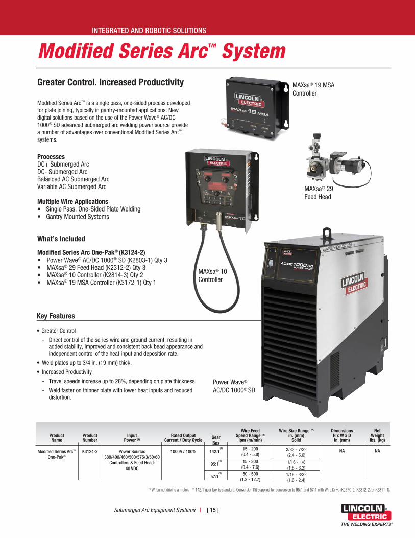
Modified Series Arc™ One-Pak®
K3124-2 Power Source: 380/400/460/500/575/3/50/60
Controllers & Feed Head: 40 VDC
1000A / 100% 142:1(1) 15 - 200
(0.4 - 5.0)3/32 - 7/32 (2.4 - 5.6)
NA NA
95:1(1) 15 - 300
(0.4 - 7.6)1/16 - 1/8(1.6 - 3.2)
57:1(1) 50 - 500
(1.3 - 12.7)1/16 - 3/32(1.6 - 2.4)
(1) When not driving a motor. (2) 142:1 gear box is standard. Conversion Kit supplied for conversion to 95:1 and 57:1 with Wire Drive (K2370-2, K2312-2, or K2311-1).
Modified Series Arc™ System
Key Features
• Greater Control
- Direct control of the series wire and ground current, resulting in added stability, improved and consistent back bead appearance and independent control of the heat input and deposition rate.
• Weld plates up to 3/4 in. (19 mm) thick.
• Increased Productivity
- Travel speeds increase up to 28%, depending on plate thickness.
- Weld faster on thinner plate with lower heat inputs and reduced distortion.
MAXsa® 29Feed Head
INTEGRATED AND ROBOTIC SOLUTIONS
Greater Control . Increased Productivity
Modified Series Arc™ is a single pass, one-sided process developed for plate joining, typically in gantry-mounted applications. New digital solutions based on the use of the Power Wave® AC/DC 1000® SD advanced submerged arc welding power source provide a number of advantages over conventional Modified Series Arc™ systems.
Processes DC+ Submerged ArcDC- Submerged ArcBalanced AC Submerged ArcVariable AC Submerged Arc
Multiple Wire Applications • Single Pass, One-Sided Plate Welding• Gantry Mounted Systems
What’s Included
Modified Series Arc One-Pak® (K3124-2) • Power Wave® AC/DC 1000® SD (K2803-1) Qty 3• MAXsa® 29 Feed Head (K2312-2) Qty 3• MAXsa® 10 Controller (K2814-3) Qty 2• MAXsa® 19 MSA Controller (K3172-1) Qty 1
MAXsa® 19 MSAController
MAXsa® 10 Controller
Power Wave®
AC/DC 1000® SD

[ 16 ] | Submerged Arc Equipment Systems
THE LINCOLN ELECTRIC COMPANY
Robotic Submerged Arc SolutionsFaster Arc Time . Consistent Quality .
Building on the digital component platform of the Power Wave® AC/DC 1000® SD power source and MAXsa® controllers and feed heads, the team at Lincoln Electric Automation developed an advanced robotic submerged arc welding system to enhance productivity for many heavy industry applications.
With robotic automation, operations can be moved to the next level with robot features such as touch sensing, path follow and vision-based arc guidance along with automated flux recovery.
Processes DC+ Submerged ArcDC- Submerged ArcBalanced AC Submerged ArcVariable AC Submerged Arc
Applications • Structural Steel• Process and Power Generation• Wind Tower Fabrication• Heavy Equipment • Offshore• Pipe Fabrication
Key Features
Robotic Submerged Arc Solutions
• Higher deposition rates at faster travel speeds
• Increased productivity and arc-on time
• Patented flux delivery system
• Engineered cable management system
• Fast digital system component communication
Contact Lincoln Electric Automation Solutions at 888.935.3878 or [email protected]
Submerged Arc Equipment Systems | [ 17 ]
APPENDIX
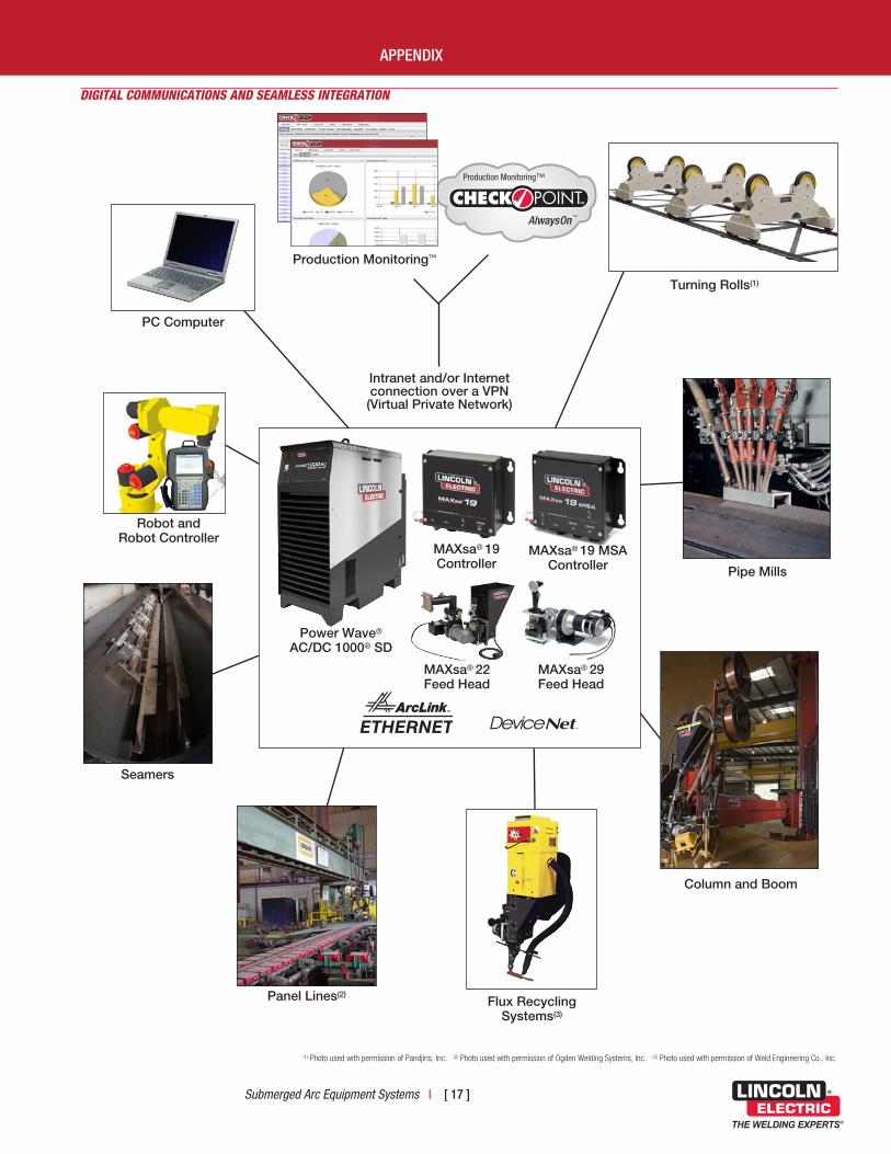
DIGITAL COMMUNICATIONS AND SEAMLESS INTEGRATION
(1) Photo used with permission of Pandjiris, Inc. (2) Photo used with permission of Ogden Welding Systems, Inc. (3) Photo used with permission of Weld Engineering Co., Inc.
Production Monitoring™
Intranet and/or Internet connection over a VPN (Virtual Private Network)
PC Computer
Turning Rolls(1)
Pipe Mills
Column and Boom
Flux Recycling Systems(3)
Panel Lines(2)
Seamers
Robot and Robot Controller
Power Wave® AC/DC 1000® SD
MAXsa® 19Controller
MAXsa® 19 MSAController
MAXsa® 29Feed Head
MAXsa® 22Feed Head
Production Monitoring™
™

[ 18 ] | Submerged Arc Equipment Systems
THE LINCOLN ELECTRIC COMPANY
RECOMMENDED EQUIPMENT
Product Number Product Description Qty . Required
K2803-1 Power Wave® AC/DC 1000® SD 1
K3048-1 Cruiser® Tractor 1
K2683-xx Heavy Duty ArcLink® Control Cable 1
K1811-xx Work Sense Lead 1
SINGLE ARC MOBILE CONFIGURATION
Connection Diagram - Cruiser® Tractor System
Work
K2683-XXArcLink® CableK3048-1
Cruiser® Tractor
WorkWeld Cable
ElectrodeWeld Cable
K1811-XXSense Lead
K2803-1Power Wave® AC/DC 1000® SD

Submerged Arc Equipment Systems | [ 19 ]
APPENDIX
SINGLE ARC CONFIGURATION
Connection Diagram - Single Arc System
K2683-XXArcLink® Cable
67 Lead
Work
K231-1 Contact Nozzle
K2803-1Power Wave® AC/DC 1000® SD
K2814-3MAXsa® 10
K2370-2MAXsa® 22
K1811-XXSense Lead
ElectrodeWeld Cable
WorkWeld Cable
K1785-XX14-Pin Cable
RECOMMENDED EQUIPMENT
Product Number Product Description Qty . Required
K2803-1 Power Wave® AC/DC 1000® SD 1
K2814-3 MAXsa® 10 Controller 1
K2370-2 MAXsa® 22 Feed Head 1
K231-1 Submerged Arc Contact Nozzle Assembly [3/32 in. (2.4 mm), 1/8 in. (3.2 mm), 5/32 in. (4.0 mm)]
1
K2683-XX Heavy Duty ArcLink® Control Cable 1
K1785-XX 14-pin Control Cable 1
K1811-XX Work Sense Lead 1
[ 20 ] | Submerged Arc Equipment Systems
THE LINCOLN ELECTRIC COMPANY
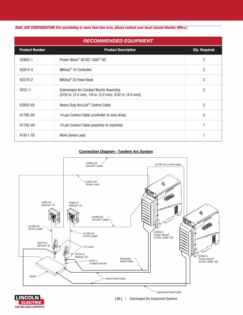
DUAL ARC CONFIGURATION (For paralleling or more than two arcs, please contact your local Lincoln Electric Office.)
Connection Diagram - Tandem Arc System
67 Lead
K1785-XX14-Pin Cable
WorkWork Weld Cable
K231-1 Contact Nozzle
K2814-3MAXsa® 10
K2814-3MAXsa® 10
K2370-2MAXsa® 22
K2370-2MAXsa® 22
Electrode Weld Cable
K2683-XXArcLink® Cable
K2683-XXArcLink® Cable
K1785-XX 14-Pin Cable
K2803-1Power Wave®
AC/DC 1000® SD
K2803-1Power Wave®
AC/DC 1000® SD
K1785-XX14-Pin Cable
K1811-XXSense Lead
ElectrodeWeld Cable
RECOMMENDED EQUIPMENT
Product Number Product Description Qty . Required
K2803-1 Power Wave® AC/DC 1000® SD 2
K2814-3 MAXsa® 10 Controller 2
K2370-2 MAXsa® 22 Feed Head 2
K231-1 Submerged Arc Contact Nozzle Assembly [3/32 in. (2.4 mm), 1/8 in. (3.2 mm), 5/32 in. (4.0 mm)]
2
K2683-XX Heavy Duty ArcLink® Control Cable 2
K1785-XX 14-pin Control Cable (controller to wire drive) 2
K1785-XX 14-pin Control Cable (machine to machine) 1
K1811-XX Work Sense Lead 1
Submerged Arc Equipment Systems | [ 21 ]
MECHANIZED SOLUTION
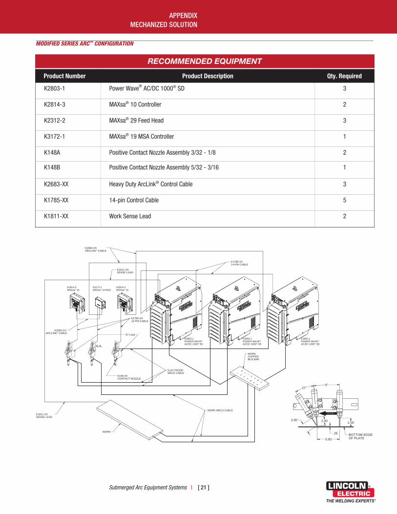
K2803-1POWER WAVE®
AC/DC 1000® SD
K2814-3MAXsa® 10
K3172-1MAXsa® 19 MSA
K2814-3MAXsa® 10
K2803-1POWER WAVE®
AC/DC 1000® SD
K2803-1POWER WAVE®
AC/DC 1000® SD
67 Lead
K1785-XX14-PIN CABLE
WORK WELD CABLE
K148-XX CONTACT NOZZLE
ELECTRODEWELD CABLE
K2683-XXARCLINK® CABLE
K1811-XXSENSE LEAD
WORKCOPPERBUS BAR
WORK
K1785-XX14-PIN CABLE
2.002.002.00
27°
.25
5.00
BOTTOM EDGEOF PLATE
K1811-XXSENSE LEAD
5°
K2683-XXARCLINK® CABLE
N.A.
RECOMMENDED EQUIPMENT
Product Number Product Description Qty . Required
K2803-1 Power Wave® AC/DC 1000® SD 3
K2814-3 MAXsa® 10 Controller 2
K2312-2 MAXsa® 29 Feed Head 3
K3172-1 MAXsa® 19 MSA Controller 1
K148A Positive Contact Nozzle Assembly 3/32 - 1/8 2
K148B Positive Contact Nozzle Assembly 5/32 - 3/16 1
K2683-XX Heavy Duty ArcLink® Control Cable 3
K1785-XX 14-pin Control Cable 5
K1811-XX Work Sense Lead 2
MODIFIED SERIES ARC™ CONFIGURATION
APPENDIX

[ 22 ] | Submerged Arc Equipment Systems
THE LINCOLN ELECTRIC COMPANY
7/32
3/16
5/32
1/8
3/32
5/64
1/16
5.6
4.8
4.0
3.2
2.4
2.0
1.6
15 50 100 200 300 400 500 .4 1.25 2.5 5 7.6 10 12.7
142:1gear ratio
(standard*)
95:1gear ratio(Included)
57:1gear ratio(Included)
WIRE FEED SPEED (IPM/MPM)
Mild Steel SAW Wire Feeding Capability
SO
LID
WIR
E D
IAM
ET
ER
(IN
CH
ES
/mm
)
DC+ SINGLE ARC
DC- SINGLE ARC
DC
DC
DC+ TWINARC®
DC+ SINGLE ARC DC- SINGLE ARCDC DC+ TWINARC®
* On MAXsa® Feed Heads

Submerged Arc Equipment Systems | [ 23 ]
RECOMMENDED ACCESSORIES AND OPTIONS
MAXsa® DRIVE ROLL KIT INFORMATION Product No .
Wire Sizes and Types
KP1899-1 3/32 - 7/32 in. Solid Wire
KP1899-2 1/16, 5/64, 3/32 in. Solid Wire
KP1899-3 .035, .045, .052 in. Solid Wire
KP1899-4 .045 - .052 in. Cored Wire
5-PIN HEAVY DUTY ARCLINK® CONTROL CABLE
[CAN BE EXTENDED UP TO 200 FT. (61 M) TOTAL LENGTH]
Length Product No .
He
avy
Duty
25 ft. (7.6 m) K2683-25
50 ft. (15.2 m) K2683-50
100 ft. (30.5 m) K2683-100
14-PIN CONTROL CABLE (CANNOT BE EXTENDED)
Length Product No .
4 ft. (1.2 m) K1785-4
12 ft. (3.7 m) K1785-12
16 ft. (4.9 m) K1785-16
25 ft. (7.6 m) K1785-25
50 ft. (15.2 m) K1785-50
100 ft. (30.5 m) K1785-100
SENSE LEAD KIT
Length Product No .
50 ft. (15.2 m) K1811-50
100 ft. (30.5 m) K1811-100
WELD POWER CABLES
Product No .
For Up to 250 ft . (75 m) @ 80% Duty Cycle
35 ft. - 2x4/0 K2163-35
60 ft. - 2x4/0 K2163-60
For Up to 250 ft . (75 m) @ 100% Duty Cycle
10 ft. - 1x3/0 K1842-10
35 ft. - 1x3/0 K1842-35
60 ft. - 1x3/0 K1842-60
APPENDIX
[ 24 ] | Submerged Arc Equipment Systems
THE LINCOLN ELECTRIC COMPANY
RECOMMENDED ACCESSORIES AND OPTIONS
Power Wave®
AC/DC 1000® SD
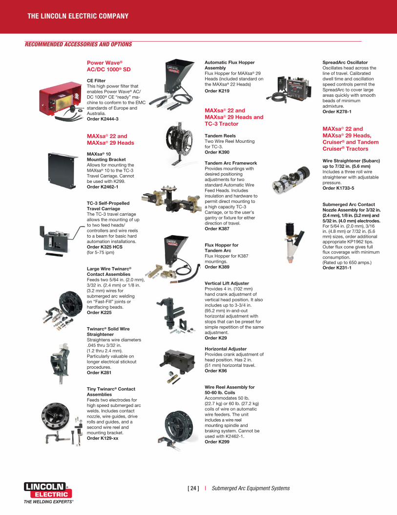
CE FilterThis high power filter that enables Power Wave® AC/DC 1000® CE “ready” ma-chine to conform to the EMC standards of Europe and Australia. Order K2444-3
MAXsa® 22 and MAXsa® 29 Heads
MAXsa® 10 Mounting BracketAllows for mounting the MAXsa® 10 to the TC-3 Travel Carriage. Cannot be used with K299.Order K2462-1
TC-3 Self-Propelled Travel CarriageThe TC-3 travel carriage allows the mounting of up to two feed heads/ controllers and wire reels to a beam for basic hard automation installations. Order K325 HCS (for 5-75 ipm)
Large Wire Twinarc® Contact AssembliesFeeds two 5/64 in. (2.0 mm), 3/32 in. (2.4 mm) or 1/8 in. (3.2 mm) wires for submerged arc welding on “Fast-Fill” joints or hardfacing beads.Order K225
Twinarc® Solid Wire StraightenerStraightens wire diameters .045 thru 3/32 in. (1.2 thru 2.4 mm). Particularly valuable on longer electrical stickout procedures.Order K281
Tiny Twinarc® Contact AssembliesFeeds two electrodes for high speed submerged arc welds. Includes contact nozzle, wire guides, drive rolls and guides, and a second wire reel and mounting bracket.Order K129-xx
Automatic Flux HopperAssemblyFlux Hopper for MAXsa® 29 Heads (included standard on the MAXsa® 22 Heads) Order K219
MAXsa® 22 and MAXsa® 29 Heads and TC-3 Tractor
Tandem ReelsTwo Wire Reel Mounting for TC-3. Order K390
Tandem Arc FrameworkProvides mountings with desired positioning adjustments for two standard Automatic Wire Feed Heads. Includes insulation and hardware to permit direct mounting to a high capacity TC-3 Carriage, or to the user’s gantry or fixture for either direction of travel.Order K387
Flux Hopper for Tandem ArcFlux Hopper for K387 mountings. Order K389
Vertical Lift AdjusterProvides 4 in. (102 mm) hand crank adjustment of vertical head position. It also includes up to 3-3/4 in. (95.2 mm) in-and-out horizontal adjustment with stops that can be preset for simple repetition of the same adjustment. Order K29
Horizontal AdjusterProvides crank adjustment of head position. Has 2 in. (51 mm) horizontal travel.Order K96
Wire Reel Assembly for 50-60 lb. CoilsAccommodates 50 lb. (22.7 kg) or 60 lb. (27.2 kg) coils of wire on automatic wire feeders. The unit includes a wire reel mounting spindle and braking system. Cannot be used with K2462-1.Order K299
SpreadArc OscillatorOscillates head across the line of travel. Calibrated dwell time and oscillation speed controls permit the SpreadArc to cover large areas quickly with smooth beads of minimum admixture. Order K278-1
MAXsa® 22 and MAXsa® 29 Heads, Cruiser® and Tandem Cruiser® Tractors Wire Straightener (Subarc) up to 7/32 in. (5.6 mm) Includes a three roll wire straightener with adjustable pressure. Order K1733-5
Submerged Arc Contact Nozzle Assembly for 3/32 in. (2.4 mm), 1/8 in. (3.2 mm) and 5/32 in. (4.0 mm) electrodes.For 5/64 in. (2.0 mm), 3/16 in. (4.8 mm) or 7/32 in. (5.6 mm) sizes, order additional appropriate KP1962 tips. Outer flux cone gives full flux coverage with minimum consumption.(Rated up to 650 amps.)Order K231-1
Submerged Arc Equipment Systems | [ 25 ]
RECOMMENDED ACCESSORIES AND OPTIONS - CONT.
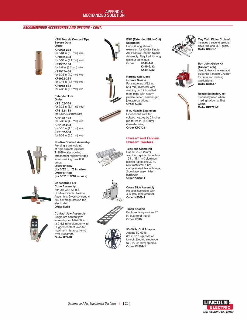
K231 Nozzle Contact TipsSevere DutyOrder KP2082-2B1 for 5/64 in. (2.0 mm) wireKP1962-3B1 for 3/32 in. (2.4 mm) wireKP1962-1B1 for 1/8 in. (3.2mm) wireKP1962-4B1 for 5/32 in. (4.0 mm) wireKP1962-2B1 for 3/16 in. (4.8 mm) wireKP1962-5B1 for 7/32 in. (5.6 mm) wire
Extended Life OrderKP3162-3B1 for 3/32 in. (2.4 mm) wireKP3162-1B1 for 1/8 in. (3.2 mm) wireKP3162-4B1 for 5/32 in. (4.0 mm) wireKP3162-2B1 for 3/16 in. (4.8 mm) wireKP3162-5B1 for 7/32 in. (5.6 mm) wire
Positive Contact AssemblyFor single arc welding at high currents (optional T12928 water cooling attachment recommended when welding over 600 amps). Order K148A (for 3/32 to 1/8 in. wire)Order K148B (for 5/32 to 3/16 in. wire)
Concentric Flux Cone AssemblyFor use with K148B, Positive Contact Nozzle Assembly. Gives concentric flux coverage around the electrode. Order K285
Contact Jaw AssemblySingle arc contact jaw assembly for 1/8-7/32 in. (3.2-5.6 mm) diameter wire. Rugged contact jaws for maximum life at currents over 600 amps. Order K226R
ESO (Extended Stick-Out)ExtensionLinc-Fill long stickout extension for K148A Single Arc Positive Contact Nozzle Assembly. Required for long stickout technique.Order K149-1/8 K149-3/32 K149-5/32
Narrow Gap Deep Groove NozzleFor single arc 3/32 in. (2.4 mm) diameter wire welding on thick walled steel plate with nearly parallel-sided, narrow gap joint preparations. Order K386
5 in. Nozzle ExtensionExtends the wire for subarc nozzles by 5 inches [up to 1/4 in. (6.4 mm) diameter wire].Order KP2721-1
Cruiser® and Tandem Cruiser® Tractors
Tube and Clamp Kit One 30 in. (762 mm) aluminum splined tube; two 15 in. (381 mm) aluminum splined tubes; one 30 in. (762 mm) steel tube; 8 clamp assemblies with keys; 2 outrigger assemblies; hardware. Order K3090-1
Cross Slide Assembly Includes two slides with 4 in. (102 mm) of travel. Order K3089-1
Track SectionEach section provides 70 in. (1.8 m) of travel.Order K396
50-60 lb. Coil Adapter Adapts 50-60 lb. (22.7-27.2 kg) coils of Lincoln Electric electrode to 2 in. (51 mm) spindle.Order K1504-1
Tiny Twin Kit for Cruiser® Includes a second spindle, drive rolls and 95:1 gears. Order K3070-1
Butt Joint Guide Kit (Tandem only) Used to track the joint and guide the Tandem Cruiser® for plate and decking applications. Order K3154-1
Nozzle Extension, 45º Frequently used when making horizontal fillet welds. Order KP2721-2
MECHANIZED SOLUTIONAPPENDIX
[ 26 ] | Submerged Arc Equipment Systems
THE LINCOLN ELECTRIC COMPANY
Curr
ent,
Volta
ge, o
r Pow
er
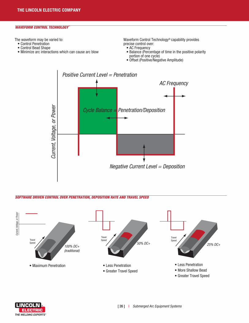
Positive Current Level = Penetration
Cycle Balance = Penetration/Deposition
Negative Current Level = Deposition
AC Frequency
WAVEFORM CONTROL TECHNOLOGY ®
Travel Speed
Curr
ent,
Volta
ge, o
r Pow
er
100% DC+ (traditional)
TravelSpeed
SOFTWARE DRIVEN CONTROL OVER PENETRATION, DEPOSITION RATE AND TRAVEL SPEED
50% DC+ Greater Travel Speed
TravelSpeed
25% DC+
TravelSpeed
• Maximum Penetration • Less Penetration• Greater Travel Speed
• Less Penetration• More Shallow Bead• Greater Travel Speed
The waveform may be varied to: • Control Penetration • Control Bead Shape • Minimize arc interactions which can cause arc blow
Waveform Control Technology® capability providesprecise control over:
• AC Frequency • Balance (Percentage of time in the positive polarity portion of one cycle) • Offset (Positive/Negative Amplitude)

Submerged Arc Equipment Systems | [ 27 ]
0
50
100
150
200
3 Arcs
2 Arcs
Pro
duct
ivity
Impr
ovem
ent
PE
RC
EN
TAG
E %
DC+ Lead ArcBalanced AC Trail Arcs
Balanced AC Lead ArcBalanced AC Trail Arcs
DC+ Lead ArcBalanced AC Trail Arcs
75% DC-, Square Wave AC Lead Arc75% DC-, Square Wave AC Trail Arcs
30% DC- Amplitude Offset
75% DC-, Square Wave AC Lead Arc75% DC-, Square Wave AC Trail Arcs
30% DC- Amplitude Offset
Greater Productivity through Enhanced Control - The Submerged Arc Advantage
SINGLE ARC AND TWINARC® SUBMERGED ARC WELDING
0
50
100
150
200
Twinarc®1 Arc
Pro
duc
tivity
Imp
rove
men
t
PE
RC
EN
TAG
E %
Single Wire DC+ Single WireBalanced AC
Single Wire75% DC-, Square Wave AC
Single WireAC EESO
(Extended ElectricalStickout)
2-Wire Twinarc®
DC+2-Wire Twinarc®
Balanced AC2-Wire
75% DC-, Square Wave AC
MULTI-ARC SUBMERGED ARC WELDING
Single Twinarc®
2 Arcs 3 Arcs
MECHANIZED SOLUTIONAPPENDIX

E9.181 02/16 © The Lincoln Electric Co. All Rights Reserved. Printed in the U.S.A.
THE LINCOLN ELECTRIC COMPANY22801 St. Clair Avenue • Cleveland, OH • 44117-1199 U.S.A.
Phone: +1.216.481.8100 • www.lincolnelectric.com
C U S T O M E R A S S I S T A N C E P O L I C Y The business of The Lincoln Electric Company is manufacturing and selling high quality welding equipment, consumables, and cutting equipment. Our challenge is to meet the needs of our customers and to exceed their expectations. On occasion, purchasers may ask Lincoln Electric for information or advice about their use of our products. Our employees respond to inquiries to the best of their ability based on information provided to them by the customers and the knowledge they may have concerning the application. Our employees, however, are not in a position to verify the information provided or to evaluate the engineering requirements for the particular weldment. Accordingly, Lincoln Electric does not warrant or guarantee or assume any liability with respect to such information or advice. Moreover, the provision of such information or advice does not create, expand, or alter any warranty on our products. Any express or implied warranty that might arise from the information or advice, including any implied warranty of merchantability or any warranty of fitness for any customers’ particular purpose is specifically disclaimed.
Lincoln Electric is a responsive manufacturer, but the selection and use of specific products sold by Lincoln Electric is solely within the control of, and remains the sole responsibility of the customer. Many variables beyond the control of Lincoln Electric affect the results obtained in applying these types of fabrication methods and service requirements.
Subject to Change – This information is accurate to the best of our knowledge at the time of printing. Please refer to www.lincolnelectric.com for any updated information.
Visit www .lincolnelectric .com


