
Article
Design and Programming of a Micro-controller-BasedSolar Tracking System
Saman Jaafar 1,†,‡ and Farhad Mahmood 2,*1 Physics department, College of science, University of Halabja ; [email protected] Physics department, College of science, University of Halabja; [email protected]* Correspondence: [email protected]
Abstract: This paper is regarding design and program an Micro-controller Arduino Uno board by1
using Arduino software to work as a photo-sensor(Active) single axial solar tracker system(SASTS).2
A solar panel, two photo-resistors (LDR) in two sides (north/south) of the photo-voltaic(PV) and3
a servo motor are connected to the Uno board, which is running a code that prepared by Arduino4
software IDE in advanced then it works as a tracking system. Here, the LDRs send the signal of5
presence or absence of the light to the board and based on that sent signal the Uno reflects a new6
signal to the servo motor to rotate and finds the light source. Lastly, the photo-sensor single axis7
tracker is made while Continuously, the system tries to face the panel to the sun and whilst changing8
the irradiance intensity it starts searching to find the angle of highest irradiance. Based on results9
that are extracted from the data, the tracker system significantly boosts the output efficiency of the10
solar panel. By using the Micro-controller Uno board, LDRs, servo motor and special designed11
mechanical base, the tracking system is constructed, based on acquired data the influence of the STS12
on the increasing the solar panel efficiency is more obvious. Significantly, the tracker system rises the13
efficiency of the PV .14
Keywords: Solar cell energy; Single Axial Solar Tracking System; Solar cell efficiency; Arduino Uno15
Board16
1. Introduction17
The high consumption of energy and the industrial revolution lead to some concerns about the18
environment and energy sources. Particularly, raising the temperature of the earth and limitation19
with the fossil sources. As a result, the researchers so far tried to highly utilize renewable energies to20
minimize those issues. The solar cell energy is one of the renewable energy that highly recommended21
as a green energy source for that situation. As Edmond Becquerel discovered the principle of PV22
system in 1839 , and due to the fact that PV is not introduce any pollution to the environment, therefore23
it can be called as a renewable energy [7]. Nowadays, the solar panel is mainly used as a major source24
to produce electrical energy in most of the countries throughout the world, due to the above mentioned25
facts. Because, it doesn’t have a bad impact on the environment such as air pollution (carbon dioxide)26
and global warming, also, the source of support is the sun while it is an infinite source of energy [1,2].27
While the produced energy is directly change with the intensity of the radiation. The intensity of the28
sun radiation changes due to deflection angle of irradiance. Thus,The output efficiency of the PV29
depends on the irradiance angle and irradiance intensity. The best and most effective angle is a normal30
angle, that means the sun light are normally radiate on the PV. Due to continuously change of the31
position of sun, the radiation energy will not be high during the day time. Since, the Solar Tracker32
System (STS) is needed to solve that problem[1]. The STS is expensive because it requires a mechanical33
base and installation. also, it requires electrical energy to work. Mainly, STS has some types:[1]:34
Preprints (www.preprints.org) | NOT PEER-REVIEWED | Posted: 30 August 2020 doi:10.20944/preprints202008.0674.v1
© 2020 by the author(s). Distributed under a Creative Commons CC BY license.

2 of 12
• Tracking based on optical sensors and microprocessor (Active)35
• Tracking based on date and time (Active)36
• Fixed or manually change tracker37
Mainly, the Active STS can be divided into Single axial and dual axial tracker. When the single axial38
STS only tracks solar in azimuth path but can’t track solar in altitude path[3]. Strongly, the cost of the39
tracker’s structure (Mechanical base, installation) depends on the amount and type of material that40
want to be used. Also, the geometry of the structure is important in order to be expensive [4]. Here,41
the paper seeks to investigate the effect of the STS on the output efficiency of the solar panel.Based on42
the measured data the efficiency has raised by 20%.43
2. Methodology44
2.1. Solar Radiation45
Solar radiation is the main key to achieve output efficiency from the PV. The irradiance hastwo-part, the first is the direct beam, that reached to the PV surface and the second is reflectedirradiance which is reflected from the PV surface, in addition to that; it does not provide energy toPV in order to produce electricity[5]. The direct irradiance received on the PV surface is given by theequation
ID = IDN cos θ (1)
whereID is direct irradiance, θ is irradiance angle, and IDN is normal direct irradiance.46
Figure 1. Sun Radiation Angle
Sun position can be determined by two angles: Altitude angle and Azimuth angle. this angle isgiven by
α = sin−1 (cos φ× cos δ× cosω + sinφ× sinδ) (2)
While the second angle is given by
cos γ =sinα× sinφ− sinδ
cosα× sinφ(3)
Both angles of altitude and azimuth can be calculated by using the information on local attitude,(φ)47
Solar declination angle,(δ) and hour angle,(ω) [6].48
2.2. Design and Equipment49
The mechanical structure of the tracker system is made of Aluminum and it has lightweight with50
servo motor together about 200g. the overall volume which may be taken by the structure is about51
30cmx25cmx25cm. it consists of A structure holder, gear shaft, panel holder and servo motor holder.52
Preprints (www.preprints.org) | NOT PEER-REVIEWED | Posted: 30 August 2020 doi:10.20944/preprints202008.0674.v1

3 of 12
It could be move in altitude path (West to East) and easily can work as a Single Axial Solar Tracking53
System(SASTS). the motion of the gear shaft is controlled by the servo motor and it rotates with low54
torque which can be handle by the servo motor (MG-996R). the main point is that the Uno board55
can supply the servo motor for rotation with specifying speed and angle. The rigidness and low air56
resistance are the good points of the mechanical structure of the SASTS.57
Figure 2. Mechanical Structure of SASTS
2.3. Uno Board58
The Arduino Uno board is an open-source micro-controller[12]. It has sets of digital and analog59
Input/Output(I/O) pins, here,as shown in the Figure 3, the digital pins of 2,3,4,5 which working as60
output pins are sending the signals to switching on/off the MOSFETs one by one and in pair and61
triple and all together. also, the analog pins such as A0,A1 get the signal from the LDR’s and A3, A4,62
A5, and A6 get the output voltages from the switching circuit and these pins work as input pins. the63
micro-controller also has USB type B which can connect to the computer and can load with Arduino64
IDE (Integrated Development Environment). It can be powered by a voltage between 9-20V and all65
digital and analog pins support 5V voltage [13].66
Figure 3. Micro-controller Uno Board
Preprints (www.preprints.org) | NOT PEER-REVIEWED | Posted: 30 August 2020 doi:10.20944/preprints202008.0674.v1
4 of 12
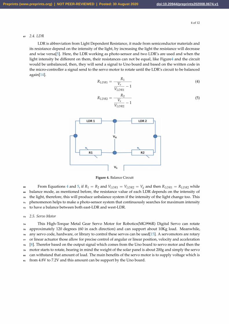
2.4. LDR67
LDR is abbreviation from Light Dependent Resistance, it made from semiconductor materials andits resistance depend on the intensity of the light, by increasing the light the resistance will decreaseand wise versa[5]. Here, the LDR working as photo-sensor and two LDR’s are used and when thelight intensity be different on them, their resistances can not be equal, like Figure4 and the circuitwould be unbalanced, then, they will send a signal to Uno board and based on the written code inthe micro-controller a signal send to the servo motor to rotate until the LDR’s circuit to be balancedagain[14].
RLDR1 =R1
Vs
VLDR1− 1
(4)
RLDR2 =R2
Vs
VLDR2− 1
(5)
Figure 4. Balance Circuit
From Equations 4 and 5, if R1 = R2 and VLDR1 = VLDR2 = Vg and then RLDR1 = RLDR2 while68
balance mode, as mentioned before, the resistance value of each LDR depends on the intensity of69
the light, therefore, this will produce unbalance system if the intensity of the light change too. This70
phenomenon helps to make a photo-sensor system that continuously searches for maximum intensity71
to have a balance between both east-LDR and west-LDR.72
2.5. Servo Motor73
This High-Torque Metal Gear Servo Motor for Robotics(MG996R) Digital Servo can rotate74
approximately 120 degrees (60 in each direction) and can support about 10Kg load. Meanwhile,75
any servo code, hardware, or library to control these servos can be used[15]. A servomotors are rotary76
or linear actuator those allow for precise control of angular or linear position, velocity and acceleration77
[8]. Therefor based on the output signal which comes from the Uno board to servo motor and then the78
motor starts to rotate, bearing in mind the weight of the solar panel is about 200g and simply the servo79
can withstand that amount of load. The main benefits of the servo motor is to supply voltage which is80
from 4.8V to 7.2V and this amount can be support by the Uno board.81
Preprints (www.preprints.org) | NOT PEER-REVIEWED | Posted: 30 August 2020 doi:10.20944/preprints202008.0674.v1

5 of 12
Figure 5. PWM Period,Duty cycle and Power
2.6. Switching Interface Circuit (Voltage regulator circuit)82
The switching interface circuit used for some purposes, the input voltage from the solar panel isaround 12V and this amount of voltage is high for microcomputer to read, as it has been mentionedbefore those pins can support maximum 5V in both digital and analog. Accordingly, the voltagedivider board is designed by R5 to R10 and the regulated voltage would be directed toward Unoboard through the outgoing signal from the digital pins. The aim of using of R1, R2, R3, R4 are just forprotection of MOSFET’s. The MOSFET’s work based on the digital pins of the Uno board, while themicro-controller would respond based on the signal from the written code on the board. Additionalpurpose of designed circuit is to have several different voltages. Each of the MOSFETs can be turnedON by the digital pins of the micro-controller and each time Uno receive one voltage data, once,thefirst switching mode has been finished then the new as a switching modes will emerge such as doubletransistors, triple and quadruple based on the aforementioned modes the Uno board can receive about14 different voltage measurements. Based on Kirchhoff’s Voltage Law (KVL), the input voltage (V-pv)and the voltage on R5 and R10 is
Vpv = VR5 + VR10 (6)
Both resistors (R5 and R10) are connected in series, thus, based on Kirchhoff’s Current Low (KCL) theamount of current which passes through each resistors are same so, equation 6 can be rearrange asshown in equation 7:
Vpv = IR5 + IR10 (7)
The output voltage which is a part of the total resistance and can be determined as equation 8.
Vo =R10
R5 + R10xVpv (8)
The output voltage of solar panel is 11.25V and R5=147KΩ and R10=100KΩ, while, the output voltageof the Uno board can be determined by substituting the values in to equation 8 as depicted in equation9.
Vo =100
100 + 147x11 = 4.45V (9)
The acquired output voltage (4.45V)is a satisfactory value for the input to the micro-controller. That83
process of determination of output voltage of switching interface board will be repeated for all other84
resistors.85
Preprints (www.preprints.org) | NOT PEER-REVIEWED | Posted: 30 August 2020 doi:10.20944/preprints202008.0674.v1
6 of 12
Figure 6. Switching Interface Circuit
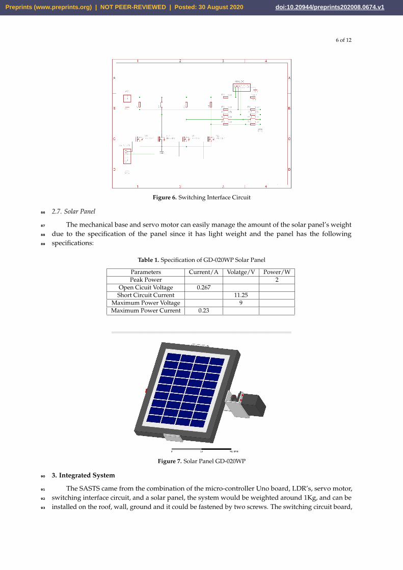
2.7. Solar Panel86
The mechanical base and servo motor can easily manage the amount of the solar panel’s weight87
due to the specification of the panel since it has light weight and the panel has the following88
specifications:89
Table 1. Specification of GD-020WP Solar Panel
Parameters Current/A Volatge/V Power/WPeak Power 2
Open Cicuit Voltage 0.267Short Circuit Current 11.25
Maximum Power Voltage 9Maximum Power Current 0.23
Figure 7. Solar Panel GD-020WP
3. Integrated System90
The SASTS came from the combination of the micro-controller Uno board, LDR’s, servo motor,91
switching interface circuit, and a solar panel, the system would be weighted around 1Kg, and can be92
installed on the roof, wall, ground and it could be fastened by two screws. The switching circuit board,93
Preprints (www.preprints.org) | NOT PEER-REVIEWED | Posted: 30 August 2020 doi:10.20944/preprints202008.0674.v1

7 of 12
the Uno board and portable battery are attached to the body of the mechanical base as shown in Figure94
8.95
Figure 8. The Tracker System in Different Angle of View
4. Flow chart96
The process of the written code in the Arduino Uno board can represented as below flow chart.97
As it is shown, the tracker system mainly depend on the LDR’s signals and the amount of error can be98
calculated by subtracting the value of westLDR from westLDR. while the intensity of light in one side99
of solar panel is greater than the other side, then an amount of error will be produced and it would be100
sensed by Uno board, therefore the Uno board sends a signal to the servo to rotate in the direction of101
higher intensity LDR and the panel should be adjusted accordingly,then the Uno board recheck the102
LDR intensities if still the Uno board sensed an amount of the error which is be greater than absolute103
value of 5 Lux then the panel will rotate accordingly, but, if the error is smaller than absolute value of 5104
Lux the system would received the voltages data as explained in the section of Switching Interface105
Preprints (www.preprints.org) | NOT PEER-REVIEWED | Posted: 30 August 2020 doi:10.20944/preprints202008.0674.v1

8 of 12
Circuit.106
Start;
error >+5
Rotate the Servotoward eastLDR
error>-5
Rotate the Servotoward westLDR
|error|<5
Get the I-V data
107
5. Operation of SASTS108
LDR’s are the eyes of the system. They try to find the sun in the sky and prepare the solar panel109
to be fixed while incoming normal radiation as proved in equation 4, 5, because the most effective110
irradiance is that rays which normally incident on the PV based on equation 1. The LDR’s lie in both111
sides of the PV as shown in Figure 2. the incoming a notification or a signal from LDR’s to the Uno112
board makes a change in the decision of the board and it will decide based on the new happened event113
and send a signal to the servo motor to rotate in the angle toward the highlighted LDR, while doing114
this process and rotating the servo as a result the new signal will come to the Uno board again from the115
LDR’s and the Uno board specify the value of error, if the error value is smaller than the value which116
has been assumed, the Uno sends a new signal to the servo motor again and stop the rotation. If the117
error is larger than the specified value the new signal is going to continue the rotation. The Uno board118
will get the voltage measures from the switching interface circuit while the error is small. Therefore,119
only voltage data will be measured, but, based on the code the uploaded to the Uno bard, the current120
and power for each data will be derived by the known resistors which have been used in the circuit.121
6. Experimental detail122
After finishing the Single Axial Solar Tracker System (SASTS) it can be used for determine the123
Maximum Power Point Tracking based on the data measurements. The system is used at the end of124
April 2020 for two days from 8:00am to 16:00 in Halabja city in Kurdistan region/Iraq. The first day125
the SASTS is working and the data have been collected while using photo-sensor tracker. The data are126
taken for each one hour its why there are some samples of the data that the prevalent has taken. In the127
second day the system used but without tracker system, it is like fixed solar panel. The aim of this two128
different situation is for proof and determine the influence of the tracker on boosting of the efficiency129
of the solar panel.130
Preprints (www.preprints.org) | NOT PEER-REVIEWED | Posted: 30 August 2020 doi:10.20944/preprints202008.0674.v1
9 of 12
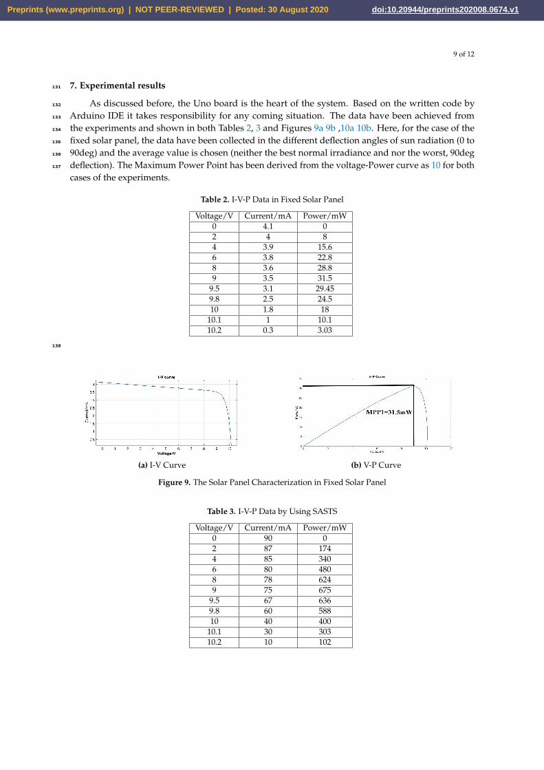
7. Experimental results131
As discussed before, the Uno board is the heart of the system. Based on the written code by132
Arduino IDE it takes responsibility for any coming situation. The data have been achieved from133
the experiments and shown in both Tables 2, 3 and Figures 9a 9b ,10a 10b. Here, for the case of the134
fixed solar panel, the data have been collected in the different deflection angles of sun radiation (0 to135
90deg) and the average value is chosen (neither the best normal irradiance and nor the worst, 90deg136
deflection). The Maximum Power Point has been derived from the voltage-Power curve as 10 for both137
cases of the experiments.
Table 2. I-V-P Data in Fixed Solar Panel
Voltage/V Current/mA Power/mW0 4.1 02 4 84 3.9 15.66 3.8 22.88 3.6 28.89 3.5 31.5
9.5 3.1 29.459.8 2.5 24.510 1.8 18
10.1 1 10.110.2 0.3 3.03
138
(a) I-V Curve (b) V-P Curve
Figure 9. The Solar Panel Characterization in Fixed Solar Panel
Table 3. I-V-P Data by Using SASTS
Voltage/V Current/mA Power/mW0 90 02 87 1744 85 3406 80 4808 78 6249 75 675
9.5 67 6369.8 60 58810 40 400
10.1 30 30310.2 10 102
Preprints (www.preprints.org) | NOT PEER-REVIEWED | Posted: 30 August 2020 doi:10.20944/preprints202008.0674.v1

10 of 12
(a) I-V Curve (b) V-P Curve
Figure 10. The Solar Panel Characterization by Using SASTS
8. Efficiency139
In this section the effective of the SASTS can find and understand on the improving the efficiencyof the PV. So, the boost of efficiency is determined by the ratio of the achieved MPP point by usingSASTS to the MPP point is obtained from a fixed solar panel. The MPP2 is obtained from using STSand MPP1 from the fixed case, the efficiency can be determining as below:
η =MPP2MPP1
× 100% (10)
where η is efficiency MPP2= 675 mW with STS achieved from the graphs, for a fixed case as shown140
in the 9b, there are fourteen MPP points but any of them are related to the specific deflection angle.141
Therefore, the Maximum and the Minimum of the MPP can be focused, that means the biggest and142
smallest angle of deflection. MPP1 = 31.5mW Now, just we will substitute the values in equation 10.143
η =MPP2MPP1
× 100% =67531.5× 100% = 21.42%144
145
9. Comparison146
The comparison section will make fine clarification for all the performed tasks. From the plotted147
data in figure 9b for the fixed case of solar panel, the MPP is low due to a high deflection angle. Based148
on equation 1 the highest intensity is obtained form the 0 angles of deflection of the sun’s rays. Its the149
main reason for low achieved MPP in that case. Meanwhile, by using SASTS, the plotted data in the150
Figure 10b were shown that the high amount of the solar radiation has been converted to the electrical151
energy, because, the MPP point is higher than the previous case. Definitely, it can be said that the main152
reason for that is the minimization of the deflection angle of radiation by the solar tracker system. The153
MPP is about 21 times greater than the MPP of the fixed case, thus the solar tracker (photo-sensor154
tracker) is so effective on boosting the output energy for the PV system.155
10. Conclusion156
Significantly, using SASTS caused to achieve more power from the solar panel and provide to157
boost efficiency. It is a good idea to use the tracker for larger projects because based on the determined158
efficiency due to using the SASTS about 21.4% rising of the efficiency has achieved. The advantages of159
the solar tracker can be mention as below points.160
? The SASTS is a system that needs low energy to work and is supported by the Uno board. But, for161
two-axial STS would need more electrical energy to handle.162
? Here, the system can be handled by the output energy of the solar panel. Therefor, the working of163
the STS can be done by the self-support of the solar panel164
? Advancements in technology and reliability in electronics and mechanics are gradually declining the165
long-term maintenance concerns about STS [11].166
? It is highly recommend for those geographical locations which don’t have more time of Sun167
Preprints (www.preprints.org) | NOT PEER-REVIEWED | Posted: 30 August 2020 doi:10.20944/preprints202008.0674.v1

11 of 12
irradiance or the intensity of the radiation is poor, means the sun radiate by the high deflected angle168
(usually north part of the earth and far locations from equator line).169
? STS caused to speed up the charging of the battery, the battery charging almost depends on the170
power and efficiency of the PV. So, when the efficiency of the PV increased the charging of the battery171
will be faster. Thus, the battery will not going to die sooner than its lifetime.172
There are some drawbacks of the SASTS as discussed below:173
? The SASTS may not be able to track all sun motion paths thus, some of the radiation time will be174
wasted and it will not be used and the output efficiency will be less than the peak value.175
? It needs energy to work, for a large project, a large amount of energy needs to handle the process176
? For its utilization, the wide and flat ground is needed. That Means, a suitable place is required to put177
the system on it. Meanwhile, the place must be wide and sufficiently far from the trees and the agent178
of shadow .179
? The construction of the mechanical base of the tracker needs cost, tools, and time. The tracker also180
needs observation and maintenance.181
182
11. Future work183
Some points about the future of this project:184
? Do the project and the experiments in the northern area of the earth because there the deflection185
angle of the incident ray is more and the influence of the using solar tracker system can be more186
understandable.187
? Use higher power solar panel since, MPP points are more sensible during finding.188
? Do the same procedure with two axial solar tracker system, it maybe the effective of the tracker will189
be highly observe.190
? Using MATLAB Simulink for doing this kind of procedures.191
192
Abbreviations193
The following abbreviations are used in this manuscript:194
195
SASTS Single Axial Solar Tracker SystemMPP Maximum Power PointPV Photo-VoltaicLDR Light Depending ResistorIDE Integrated Development Environment
196
References197
1. F. M. Hoffmann, R. F. Molz, J. V. Kothe, E. O. B. Nara, and L. P. C. Tedesco, “Monthly profile analysis based198
on a two-axis solar tracker proposal for photovoltaic panels,” Renew. Energy, vol. 115, pp. 750–759, 2018.199
2. T. Hong et al., “A preliminary study on the 2-axis hybrid solar tracking method for the smart photovoltaic200
blind,” Energy Procedia, vol. 88, pp. 484–490, 2016.201
3. J. Song, Y. Zhu, D. Xia, and Y. Yang, “A photovoltaic solar tracking system with bidirectional sliding axle for202
building integration,” Energy Procedia, vol. 61, pp. 1638–1641, 2014.203
4. H. Zlatanov and G. Weinrebe, “CSP and PV solar tracker optimization tool,” Energy Procedia, vol. 49, pp.204
1603–1611, 2013.205
5. D. F. Da Silva and D. Acosta-Avalos, “Light dependent resistance as a sensor in spectroscopy setups using206
pulsed light and compared with electret microphones,” Sensors, vol. 6, no. 5, pp. 514–525, 2006.207
6. S. Ahmad, S. Shafie, and M. Z. A. Ab Kadir, “Power Feasibility of a Low Power Consumption Solar Tracker,”208
Procedia Environ. Sci., vol. 17, pp. 494–502, 2013.209
7. A. Goetzberger and A. Goetzberger, “Workshop on " Physics for Renewable Energy " Crystalline Silicon210
Solar Cells Crystalline Silicon Solar Cells,” 2005.211
Preprints (www.preprints.org) | NOT PEER-REVIEWED | Posted: 30 August 2020 doi:10.20944/preprints202008.0674.v1

12 of 12
8. L. Szabó and A. Szaniszló, “Monthly profile analysis based on a two-axis solar tracker proposal for212
photovoltaic panels,” Int. Rev. Appl. Sci. Eng., vol. 8, no. 1, pp. 37–43, 2017.213
9. S. Sugiyama, “Multi-Stage PWM DC Servo Motor Control,” IFAC Proc. Vol., vol. 22, no. 18, pp. 341–345,214
2017.215
10. L. Louis, “SOLAR POWER PLANT STATION IN FISHLAND,” Int. J. Control. Autom. Commun. Syst., vol.216
1, no. 2, pp. 21–29, 2016.217
11. “Solar power world.pdf.” , Advantages and disadvantages of Solar Tracker system,218
https://www.solarpowerworldonline.com/2016/05/advantages-disadvantages-solar-tracker-system/219
12. "What is Arduino?". learn.sparkfun.com. Retrieved 4 February 2018220
13. "Arduino". store.arduino.cc. Retrieved 10 March 2020.221
14. "Photoresistor" https : //www.electronics − notes.com/articles/electroniccomponents/resistors/light −222
dependent− resistor− ldr.php.223
15. "MG996R High Torque Metal Gear Dual Ball Bearing Servo" https :224
//www.electronicoscaldas.com/datasheet/MG996RTower− Pro.pd f .225
Preprints (www.preprints.org) | NOT PEER-REVIEWED | Posted: 30 August 2020 doi:10.20944/preprints202008.0674.v1


