Innovative Systems Design and Engineering www.iiste.org
ISSN 2222-1727 (Paper) ISSN 2222-2871 (Online)
Vol.5, No.4, 2014
20
Design and Performance of Adaptive Antenna
System in LTE 3GPP Transceivers Based Fourier
Signals in ITU Channels
Dr. Mohammed Aboud Kadhim 1*
Dr. Adnan Hussein Ali 2 Mohannad J Mnati
3
Foundation of Technical Education, Institute of Technology Baghdad
*Email: [email protected]
Abstract
3G LTE is next generation step in mobile communications with the promise of peak download rates of at least
100 Mbit/s and upload rates 50 Mbit/s. The evolved version of Long Term Evolution is LTE-Advanced which is
being developed by the Third Generation Partnership Project (3GPP). LTE-Advanced will meet or go beyond the
requirements of the International Telecommunication Union (ITU) for the fourth generation (4G) radio
communication standard. In this paper, we investigate the performance of Adaptive Antenna System in the LTE
3GPP Transceivers. Adaptive Antenna System (AAS) has been developed to adaptively correct antenna
impedance mismatch for the LTE 3GPP Transceivers. (AAS) has been deployed at the receiver module to
reduce the fading effects caused by proposed channels model. (AAS) uses various beamforming techniques to
focus the wireless beam between the base station and the subscriber station. In this work, the transmitter (SS)
and receiver (BS) are fixed and AAS installed at the receiver is used to direct the main beam towards the desired
LOS signal and nulls to the multipath signals. Least Mean Square (LMS) algorithm is used. It has been proved
through MATLAB simulations that the performance of the system significantly improves by AAS in
International Telecommunication Union (ITU) channels , where beamforming is implemented in the direction
of desired user. The performance of the system more increases by increasing the number of antennas at receiver.
Keywords: OFDM, LTE 3GPP, LMS, ITU, AAS.
1. Introduction
Long Term Evolution (LTE) is the next step forward in cellular 3G services. LTE will bring many technical
benefits to cellular networks. Bandwidth will be scalable from 1.25 MHz to 20MHz. This will suit the needs of
different network operators that have different bandwidth allocations, and also allow operators to provide
different services based on spectrum. LTE is also expected to improve spectral efficiency in 3G networks,
allowing carriers to provide more data and voice services over a given bandwidth (3GPP TS36.300, 2011). This
paper provides an overview of the LTE physical layer (PHY), including technologies that are new to cellular
such as LTE 3GPP transceivers based Fourier signals in ITU channels with adaptive antenna system. The 3GPP
Long Term Evolution (LTE) represents a major advance in cellular technology. LTE is designed to meet carrier
needs for high-speed data and media transport as well as high-capacity voice support well into the next decade. It
encompasses high-speed data, multimedia unicast and multimedia broadcast services. Although technical
specifications are not yet finalized, significant details are emerging (Ericsson, 2009). This paper focuses on the
LTE physical layer (PHY) with adaptive antenna system. The LTE PHY is a highly efficient means of conveying
both data and control information between an enhanced base station and mobile user equipment. The LTE PHY
employs some advanced technologies that are new to cellular applications. These include Orthogonal Frequency
Division Multiplexing (OFDM) LTE employs OFDM for downlink data transmission. OFDM is a well-known
modulation technique, but is rather novel in cellular applications. A brief discussion of the basic properties and
advantages of this method is therefore warranted. When information is transmitted over a wireless channel, the
signal can be distorted due to multipath. Typically there is a line-of-sight path between the transmitter and
receiver. The Wireless MAN-OFDM interface can be exceedingly limited by the presence of fading caused by
multipath propagation and as result the reflected signals arriving at the receiver are multiplied with different
delays, which cause Inter-symbol interference (ISI) (D. Sirkova, 2006). OFDM basically is designed to
overcome this issue and for situations where high data rate is to be transmitted over a channel with a relatively
large maximum delay. If the linger of the received signals is larger than the guard interval, ISI may cause severe
degradations in system performance. To solve this issue multiple antenna array can be used at the receiver,
which provides spectral efficiency and interference suppression (Clercks, 2007). Adaptive Antenna System
(AAS) is an optional feature in LTE 3GPP standard but to enhance the coverage, capacity and spectral
efficiency, it should be essential for an OFDM air interface. It has an advantage of having single antenna system
at the subscriber station and all the burden is on base station. An array of antenna is installed at the base station
to reduce inter-cell interference and fading effects by providing either beamforming or diversity gains. When

Innovative Systems Design and Engineering www.iiste.org
ISSN 2222-1727 (Paper) ISSN 2222-2871 (Online)
Vol.5, No.4, 2014
21
small spacing is adopted, the fading is highly correlated and Beamforming techniques can be employed for
interference rejection as compared to Diversity-oriented schemes. As a result receiver can separate the desired
LOS signal from the multipath signals and nulls are formed at the interfering signals (KARAKAYA, 2009,
Daniele Borio, 2006). The objective of this paper is to develop the physical layer of LTE 3GPP Transceivers
standard by uses adaptive antenna array at the receiver to combat multi-path channel. The increase in use of
Wireless Broadband Systems (WBS) has put promoters of WBS in a competitive race with their counter parts.
It’s a well known fact that wireless systems are way ahead with their counter parts when it comes to deployment
and ease of installation thus reaching places where one cannot even think of deploying a wired solution for
broadband communication. However wireless systems have been unable to tackle bandwidth issues for the past
many years and therefore remained unable to address QoS parameters until now. In past recent years
considerable amount of research work has been conducted to improve the performance of the system in terms of
increasing the capacity and range. One such technology that is proving to be very useful to cater these issues is
“Smart Antenna Systems” (SAS)(K.Sheikh, 1999, Lal Chand Godara, 2004). Smart Antenna System uses
advanced signal processing techniques to construct the model of the channel. Using the knowledge of the
channel, SAS uses beamforming techniques in order to steer or direct a radio beam towards desired users and
null steering towards the interferers (C.Godara, 1997). It works by adjusting the angles and width of the antenna
radiation pattern. SAS consist of set or radiating elements capable of sending and receiving signals in such a way
that radiated signals combine together to form a switch able and movable beam towards the user. However it
may be noted that the hardware of the smart antenna does not make them “smart”, in fact it is the signal
processing technique that is used to focus the beam of the radiated signals in the desired direction. This process
of combining the signal and then focusing the signal in particular direction is called beamforming (C.Godara,
1997). On the other hand Adaptive Array System acts in a different manner as compared to switched beam
Antenna system. It works by keep a constant track of the mobile user by focusing a main beam towards the user
and at the same time jamming the interfering signals by forming nulls in direction towards them. A brief
comparison of these two approaches can be best observed from (C.Godara, 1997) which show beamforming
lobes and nulls. It can be seen that for the Adaptive Array the main beam is towards users and nulls to interferer
(C.Godara, 1997). A BS can serve multiple subscriber stations with higher throughput by using AAS. For that
space Division multiplex is used to separate (in space) multiple SSs that are transmitting and receiving at the
same time over the same sub-channel. By using AAS, Interference can be severely reduced that is originated
from the other Subscriber Stations or the multipath signals from the same SS by steering the nulls towards the
desired interference(C.Godara, 1997). An adaptive antenna system performs the following functions. First it
calculates the direction of arrival of all incoming signals including the multipath signal and the interferers using
the Direction of Arrival (DOA) algorithms with for example MUSIC and ESPIRIT(C.Godara, 1997). This is just
two of many used algorithms. DOA information is then fed into the weight upgrade algorithm to calculate the
corresponding complex weights.
2. The Simulation Block Diagram
The new proposed structures for the LTE 3GPP transceivers with adaptive antenna system will be studied in this
paper. The Block diagram in Figure 1 represents the whole system model for proposed LTE transceiver design
with adaptive antenna system.
Figure 1. Simulation Block Diagram
The block diagram structure is divided into four main sections: transmitter, receiver, adaptive antenna array
algorithm and channel. In this section the system models that have been used in the LTE simulator will be
presented. The used system model is outlined in Figure 1 In transmitter side the digital random data set is

Innovative Systems Design and Engineering www.iiste.org
ISSN 2222-1727 (Paper) ISSN 2222-2871 (Online)
Vol.5, No.4, 2014
22
generated uniformly. CRC Insertion: A 24-bits CRC is calculated and appended at the end of every transport
block. CRC allows receiver to detect residual errors from the decoded transport block. The block diagram for
CRC insertion is shown in Figure 1. The current 3G systems use turbo coding scheme, but due to the high peak
data rates supported by LTE (C. Berrou, 1993) , it becomes imperative to know if this same turbo coding scheme
can scale to high data rates while maintaining reasonable decoding complexity. It is currently debated that turbo
coding has a particular drawback that it is not amenable to parallel implementations which limit the achievable
decoding speeds. The underlying reason behind this issue is the contention for memory resources among parallel
processors which occurs as a result of the turbo code internal interleaver. On the other hand, it is argued that
turbo codes can also employ parallel implementations if turbo internal interleavers can be made contention-free.
These blocks of digital data set have been paralleled and mapped into complex data blocks using 16-QAM
modulation technique. Every complex data block referred to a symbol of data is attached to an individual sub-
carrier. The Inverse Fast Fourier Transform (IFFT) is used in order to generate the time version of transmitted
signal. The time domain signals corresponding to all subcarriers are orthogonal to each other. However, the
frequency spectrum overlaps. After this, the data converted from the parallel to the serial form are fed to the ITU
channels more information about ITU channels in (International Telecommunication Union, 2000). In This
section will introduce the system model of an N subcarrier OFDM system with transmit antenna and MR receive
antennas in the presence of transmit antenna and path correlations. The worst performance of the ITU channel is
due to multipath effect, delay spread and Doppler effects. Although the impact of the delay spread and the
Doppler effect is low so the major degradation in the performance is due to the multipath effects. There are
various methods to reduce the multipath effect. However in this model it is done by implementing AAS. For that
adaptive beamforming algorithm such as Least Mean Square (LMS), be used (KUN, 2009, ZHAO, 2009). The
calculated weight is then multiplied by the signal from the antenna array and required radiation pattern is formed.
The block diagram of an antenna array system. So a beam is steered in the direction of the desired signal and the
user is tracked as it moves while placing nulls at interfering signal directions by constantly updating the complex
weights by using any of the beamforming algorithms.AAS has the feature that requires only multiple antennas at
the BS and thus putting whole burden on the BS. As AAS is known to reduce inter-cell interference and
multipath fading by providing beamforming. So multiple antennas are installed at the receiver and performance
is investigated in the presence of receiver antennas. The receiver performs the same operations as the transmitter,
but in a reverse order. In addition, OFDM includes operations for compensation for the destructive ITU channels.
3. Simulation and Results
The reference model specifies a number of parameters that can be found in Table (1).
Table (1) System parameters
Transmission Bandwidth 2.5 MHz
Sub-frame duration 0.5ms
Sub-carrier spacing 15KHz
Sampling Frequency 3.84MHz
FFT Size 256
OFDM symbol per slot (short/long CP 7/6
CP length (μsec/samples)
SHORT (4.69/18) x 6
(5.21/20) x 1
LONG (16.67/64)
Modulation type 16QAM
Channel coding Turbo
Channel type ITU Channel
Receiver decoder type Soft sphere detection (SSD)
Number of iterations 1000
In this section the simulation of the proposed channel estimation algorithms for the existing in LTE 3GPP
Baseband Transceiver and comparing between when using AAS and without using AAS is executed, beside the
BER performance of the system regarded in ITU channel models.
3.1AWGN Channel Performance
In this scenario, the results obtained were encouraging, the system when using AAS and without using AAS can
be seen that for BER=10-3
the SNR required when without using AAS is about 16.2 dB while when using AAS is
about 14.3 dB, from Figure 2 it is found that the channel estimation (MMSE) outperforms significantly other
system for this channel model.

Innovative Systems Design and Engineering www.iiste.org
ISSN 2222-1727 (Paper) ISSN 2222-2871 (Online)
Vol.5, No.4, 2014
23
0 2 4 6 8 10 12 14 16 18 2010
-4
10-3
10-2
10-1
100
SNR dB
BE
R
without AAS
with AAS
Figure 2. BER performance of LTE 3GPP Baseband Transceiver in AWGN channel
3.2 AWGN plus Multipath Channel Performance
In this general channel scenario, in the next sections the relevant results are discussed 3.2.1 Indoor Channel A
In this simulation profile some influential results were obtained, the system when using AAS and without using
AAS it can be seen that for BER=10-3
the SNR required when without using AAS is about 21 dB while when
using AAS the SNR is about 18 dB from, Figure 3 it is found that when using AAS outperforms significantly
other system for this channel model.

Innovative Systems Design and Engineering www.iiste.org
ISSN 2222-1727 (Paper) ISSN 2222-2871 (Online)
Vol.5, No.4, 2014
24
0 5 10 15 20 2510
-4
10-3
10-2
10-1
100
SNR dB
BE
R
without AAS
with AAS
Figure.3. BER performance of LTE 3GPP Baseband Transceiver in AWGN plus Multipath Indoor A
3.2.2 Indoor Channel B
In this channel, the results are depicted in Figure 4 it can be seen that for BER=10-3
the SNR required for the
system when without using AAS is about 27 dB, while when using AAS the SNR is about 24 dB, from Figure 4
it is found that when using AAS outperforms significantly than others systems for this channel model.

Innovative Systems Design and Engineering www.iiste.org
ISSN 2222-1727 (Paper) ISSN 2222-2871 (Online)
Vol.5, No.4, 2014
25
0 5 10 15 20 25 3010
-4
10-3
10-2
10-1
100
SNR dB
BE
R
without AAS
with AAS
Figure 4. BER performance of LTE 3GPP Baseband Transceiver in AWGN & Multipath Indoor B
3.2.3 Pedestrian Channel A
In the pedestrian profile, two different situations were regarded: a stationary and a moving person
3.2.3.1 Pedestrian Channel A (a stationary person):
Using similar methodology as in the previous section, simulations for this channel the result depicted in Figure 5
it can be seen that for BER=10-3
the SNR required for the system when without using AAS is about 24 dB while
when using AAS the SNR is about 21 dB. Also from Figure 5 it is found that when using AAS outperforms
significantly than others systems for this channel model.

Innovative Systems Design and Engineering www.iiste.org
ISSN 2222-1727 (Paper) ISSN 2222-2871 (Online)
Vol.5, No.4, 2014
26
0 5 10 15 20 25 3010
-4
10-3
10-2
10-1
100
SNR dB
BE
R
without AAS
with AAS
Figure 5. BER performance of LTE 3GPP Baseband Transceiver in AWGN & Multipath Stopped Pedestrian A
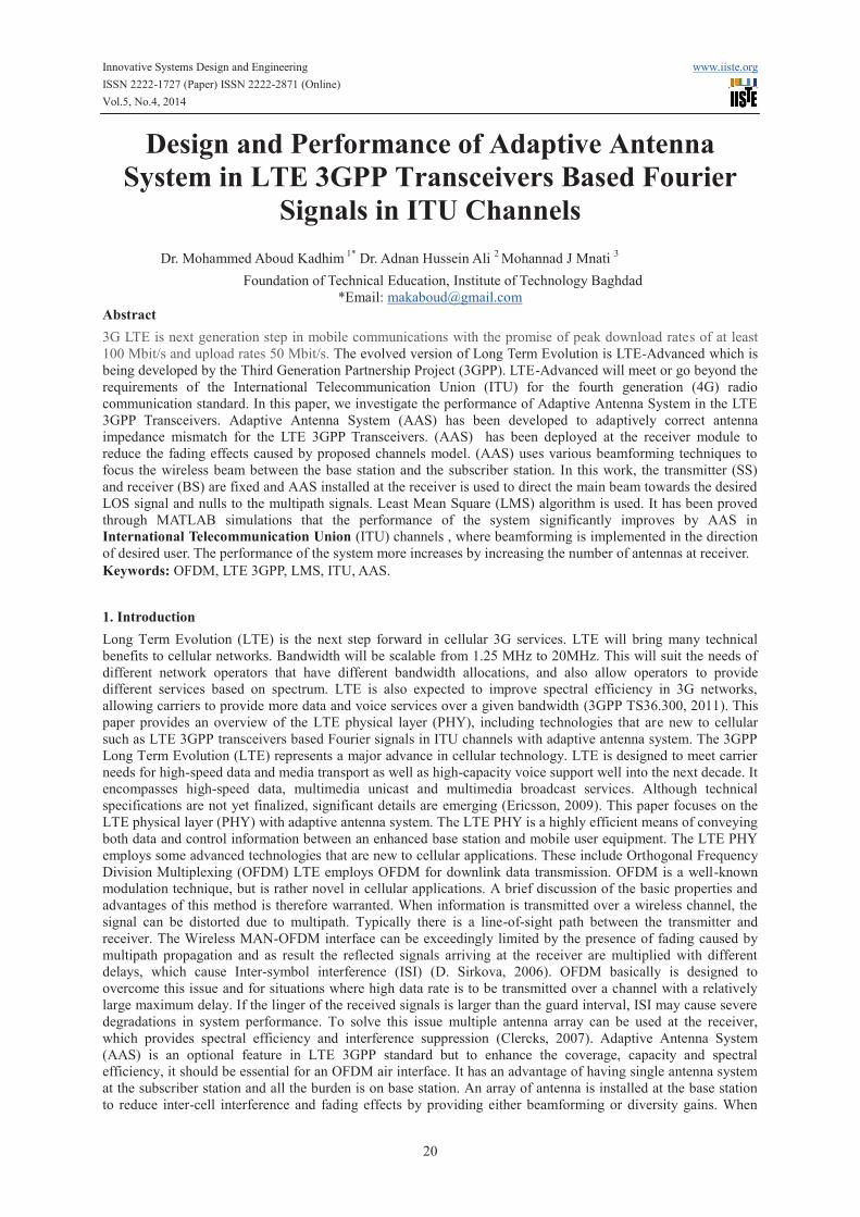
3.2.3.2 Pedestrian Channel A (a moving person):
In this model, the results obtained were encouraging. The system when using AAS and without using AAS it can
be seen that for BER=10-3
the SNR required is about 33.5 dB when without using AAS while when using AAS
the SNR is about 29 dB from Figure 6 it is found that when using AAS the system is best significantly other
system for this channel model.
Innovative Systems Design and Engineering www.iiste.org
ISSN 2222-1727 (Paper) ISSN 2222-2871 (Online)
Vol.5, No.4, 2014
27
0 5 10 15 20 25 30 35 4010
-4
10-3
10-2
10-1
100
SNR dB
BE
R
without AAS
with AAS
Figure 6. BER performance of LTE 3GPP Baseband Transceiver in AWGN & Multipath moving Pedestrian A
3.2.4 Pedestrian Channel B
Using such as methodology as in the previous section, simulations for both a stationary and a moving pedestrians
were carried out:
3.2.4.1 Pedestrian Channel B (a stationary person):
In this state, the results obtained were hopeful. The system when using AAS and without using AAS it can be
seen that for BER=10-3
the SNR required when without using AAS is about 36.5 dB while when using AAS the
SNR is about 31.5 dB from Figure 7 it is found that when using AAS is better significantly other system for this
channel model

Innovative Systems Design and Engineering www.iiste.org
ISSN 2222-1727 (Paper) ISSN 2222-2871 (Online)
Vol.5, No.4, 2014
28
0 5 10 15 20 25 30 35 40 4510
-4
10-3
10-2
10-1
100
SNR dB
BE
R
without AAS
with AAS
Figure 7. BER performance of LTE 3GPP Baseband Transceiver in AWGN & Multipath Stationary Pedestrian B
3.2.4.2 Pedestrian Channel B (a moving person):
In this scenario, the results obtained were encouraging. it can be seen that for BER=10-3
the SNR required when
without using AAS is about 42.5 dB, while when using AAS the system showed a performance 36.25 dB better
than when without using AAS. These results are presented in Figure 8.

Innovative Systems Design and Engineering www.iiste.org
ISSN 2222-1727 (Paper) ISSN 2222-2871 (Online)
Vol.5, No.4, 2014
29
0 5 10 15 20 25 30 35 40 45 5010
-4
10-3
10-2
10-1
100
SNR dB
BE
R
without AAS
with AAS
Figure 8. BER performance of LTE 3GPP Baseband Transceiver in AWGN & Multipath a moving person
Pedestrian B
3.2.5 Vehicular Channel A
In this channel was proposed for communication links under mobility, i.e., vehicular use. However, simulations
under these conditions were performed to get a sense of the effects and to eventually reflect on solutions to
combat the negative consequences. In this section the performance of the link under the user-channel vehicular A
profile with 60 km h is addressed the results obtained for the user-channel vehicular A. As shown in Figure 9
when without using AAS clearly poor performance and it can be seen that for BER=10-3
the SNR required when
using AAS the system performed is about 40dB.

Innovative Systems Design and Engineering www.iiste.org
ISSN 2222-1727 (Paper) ISSN 2222-2871 (Online)
Vol.5, No.4, 2014
30
0 5 10 15 20 25 30 35 40 4510
-4
10-3
10-2
10-1
100
SNR dB
BE
R
without AAS
with AAS
Figure 9. BER performance of LTE 3GPP Baseband Transceiver in AWGN & Multipath a Vehicular Channel A
3.2.5 Vehicular Channel B
In this section, we present the results obtained under the user-channel vehicular B profile with speed 120km h. It
is clear that all systems performed poorly since none of them can combat the multipath and Doppler spread
combined effect of this kind of channel these results are presented in Figure 10. Important results can be taken
from Table (2); in this simulation, in most scenarios, by using AAS system was better than when without using
AAS. By using AAS proved its effectiveness in combating the multipath effect on the channels.

Innovative Systems Design and Engineering www.iiste.org
ISSN 2222-1727 (Paper) ISSN 2222-2871 (Online)
Vol.5, No.4, 2014
31
0 5 10 15 20 25 30 35 40 4510
-3
10-2
10-1
100
SNR dB
BE
R
without AAS
with AAS
Figure 10. BER performance of LTE 3GPP Baseband Transceiver in AWGN & Multipath a Vehicular Channel B
Table (2) Performance Comparison and Analysis
A number of important results can be taken from Table (2); In this simulation, in most scenarios, the LTE 3GPP
Baseband Transceiver with AAS was better than the LTE 3GPP Baseband Transceiver without AAS user-channel
characteristics under which wireless communications is tested or used have important impact on the systems
overall performance. It became clear that ITU channels with larger delay spread are a bigger challenge to any
system. The AAS system proved its effectiveness in combating the multipath effect on the ITU fading channels.
4. Conclusion
In this paper, the LTE 3GPP Baseband Transceiver with AAS structure was proposed and tested. These tests were
carried out to confirm its successful operation and its possibility of implementation. It can be concluded that this
structure accomplishes much lower bit error rates. In AWGN, and other channels the LTE 3GPP Baseband
Transceiver with AAS outperform than without using AAS therefore, this structure can be considered as an
alternative to the conventional LTE 3GPP Baseband Transceiver structure. It can be concluded from the results
obtained, that S/N measure can be successfully increased using the proposed AAS designed method. The key
contribution of this paper was the execution of the LTE 3GPP Baseband Transceiver PHY layer based the AAS
structure. Simulations provided proved that proposed design accomplishes much lower and it can be used at high
transmission rates.
References

Innovative Systems Design and Engineering www.iiste.org
ISSN 2222-1727 (Paper) ISSN 2222-2871 (Online)
Vol.5, No.4, 2014
32
3GPP TS36.300 2011. ''Evolved Universal Terrestrial Radio Access (E-UTRA) and Evolved Universal Terrestrial
Radio Access Network (E-UTRAN); Overall description.
C. BERROU, A. G. A. P. T. 1993. Near Shannon Limit Error-Correcting Coding and Decoding: Turbo Codes.
Proceedings ICC 93, Geneva Switzerland, 1064-1070.
C.GODARA 1997. Application of Antenna Array to Mobile communications, Part II: Beam-forming and DOA
considerations. Proceedings of the IEEE, 85.
CLERCKS, C. O. A. B. 2007. MIMO Wireless Communications: From Real- World Propagation to Space-Time
Code Design. Elsevier.
D. SIRKOVA 2006. Overview of COST 273 Part I: propagation modelling and channel characterization. Sofia,
Bulgaria
DANIELE BORIO, L. C., LETIZIA LO PRESTI AND MARINA MONDIN, 2006. Beamforming and
Synchronization Algorithms Integration for OFDM HAP-Based Communications International Journal
of Wireless Information Networks, 13.
ERICSSON 2009. LTE-an introduction. White Paper.
INTERNATIONAL TELECOMMUNICATION UNION 2000. Recommendation ITU-R M.1225, Guidelines
for Evaluation of Radio Transmission Technologies for IMT-2000.
K.SHEIKH, D. G., D.GORE, A.PAULRAJ 1999. Smart Antennas for Broadband Wireless Access Networks.
IEEE Communication Magazine.
KARAKAYA, B., ARSLAN, H., CURPAN, H. A, 2009. An adaptive channel interpolator based on Kalman filter
for LTE uplink in high Doppler spread environments. EURASIP Journal on Wireless Commun. and
Networking, Article ID 893751.
KUN, Z., XIUBING, Z, 2009. A new modified robust variable step size LMS algorithm. In Proc. Industrial
Electronics and Applications, 2699 – 2703.
LAL CHAND GODARA 2004. Smart Antennas,Book
ZHAO, S., MAN, Z., KHOO, S., WU, H. R, 2009. Variable step size LMS algorithm with a quotient form.
Signal Processing.

Innovative Systems Design and Engineering www.iiste.org
ISSN 2222-1727 (Paper) ISSN 2222-2871 (Online)
Vol.5, No.4, 2014
33
AUTHORS’ BIOGRAPHIES
Dr. Mohammed Aboud Kadhim
Received his B.Sc., and M.Sc. in Electrical and Electronic Engineering from the Faculty of Electrical and
Electronic Engineering, Communication Engineering, University of Technology in 1996 and 2002, and he
received his PhD in Electrical and Electronics Engineering , Wireless and Mobile Systems from the School of
Electrical and Electronics Engineering, USM University, Malaysia in 2011. He is currently a Lecturer ,
researcher and training supervisor at the Foundation of Technical Education, Baghdad, Iraq. His current research
interests include Microstrip Antennas, Implantable Antennas for Medical Applications, Silicon-based Millimeter-
Wave/THz on-Chip Antennas, Low-Temperature Co-fired Ceramic-based System-on-Package Technology,
Microwave Circuits, Radio-over-Fiber Techniques, WiMAX Transceivers Design, Electronic Circuit Design,
OFDM System Design , RF Systems, Wireless Systems , Wired &Wireless Network Administration.
Dr. Adnan Hussein Ali
The Author is a Lecturer in the Computer Engineering Department at Institute of Technology, Baghdad, IRAQ.
He has been awarded a Doctor of Philosophy in Laser and Opto-Electronics Engineering from University of
Technology, Baghdad, in 2007. He has studied Master of Science in Electronics Engineering, Cupper Vapor
Laser's Power supply at University of Technology, Baghdad in 2000. He has gained Bachelor in Electrical and
Electronic Engineering from University of Technology, Baghdad, in 1987. Currently he is the Deputy Dean of
Institute of Technology, Baghdad, IRAQ. His research interests are Radio over Fiber, Wireless Network, Laser's
Power supply and OPNET.
Assist Lecturer Eng. Mohannad J Mnati
Received his B.Sc. in Electrical and Electronics from the Faculty of Electrical Engineering, University of
Technology Baghdad, Iraq in 2000, and received the M.Sc. degree in Electronic engineering from Faculty of
Electrical Engineering, University of Technology Baghdad, Iraq in 2005. Currently he is Assist Lecturer,
Researcher and training supervisor, Dep. of Electronic in Institute of Technology Baghdad. His research interests
include, Electronic circuit design, Wired& Wireless Network Administration.

The IISTE is a pioneer in the Open-Access hosting service and academic event
management. The aim of the firm is Accelerating Global Knowledge Sharing.
More information about the firm can be found on the homepage:
http://www.iiste.org
CALL FOR JOURNAL PAPERS
There are more than 30 peer-reviewed academic journals hosted under the hosting
platform.
Prospective authors of journals can find the submission instruction on the
following page: http://www.iiste.org/journals/ All the journals articles are available
online to the readers all over the world without financial, legal, or technical barriers
other than those inseparable from gaining access to the internet itself. Paper version
of the journals is also available upon request of readers and authors.
MORE RESOURCES
Book publication information: http://www.iiste.org/book/
Recent conferences: http://www.iiste.org/conference/
IISTE Knowledge Sharing Partners
EBSCO, Index Copernicus, Ulrich's Periodicals Directory, JournalTOCS, PKP Open
Archives Harvester, Bielefeld Academic Search Engine, Elektronische
Zeitschriftenbibliothek EZB, Open J-Gate, OCLC WorldCat, Universe Digtial
Library , NewJour, Google Scholar


