
MANUAL
CAR-TRUCK
FORD DIVISION FORD MOTOR COMPANY

Copyright © 2010, Forel Publishing Company, LLC, Woodbridge, Virginia
All Rights Reserved. No part of this book may be used or reproduced in any manner whatsoeverwithout written permission of Forel Publishing Company, LLC. For information write to Forel
Publishing Company, LLC, 3999 Peregrine Ridge Ct., Woodbridge, VA 22192
1955 Fordomatic Shop ManualEAN: 978-1-60371-005-3
ISBN: 1-60371-005-1
Forel Publishing Company, LLC3999 Peregrine Ridge Ct.Woodbridge, VA 22192
Email address: [email protected]: http://www.ForelPublishing.com
This publication contains material that is reproduced and distributed under a license from FordMotor Company. No further reproduction or distribution of the Ford Motor Company material is
allowed without the express written permission of Ford Motor Company.
NNoottee ffrroomm tthhee EEddiittoorr
This product was created from the original Ford Motor Company’s publication. Every effort hasbeen made to use the original scanned images, however, due to the condition of the material;some pages have been modified to remove imperfections.
Disclaimer
Although every effort was made to ensure the accuracy of this book, no representations orwarranties of any kind are made concerning the accuracy, completeness or suitability of theinformation, either expressed or implied. As a result, the information contained within this bookshould be used as general information only. The author and Forel Publishing Company, LLCshall have neither liability nor responsibility to any person or entity with respect to any loss ordamage caused, or alleged to be caused, directly or indirectly by the information contained inthis book. Further, the publisher and author are not engaged in rendering legal or otherprofessional services. If legal, mechanical, electrical, or other expert assistance is required, theservices of a competent professional should be sought.

FOREWORD
Complete service information for the 1955 Fordomatic transmission is presented in
this manual. All the procedures needed to check, adjust, replace, or repair the various
units of the transmission and torque converter are included.
The manual is arranged in seven chapters as listed in the Table of Contents on the
next page. The section headings under each chapter title indicate the subjects covered
in the chapter.
Chapter ONE describes the construction and operation of the 1955 Fordomatic trans
mission and torque converter. Diagrams showing the positions of the gears, clutches, bands,
and servos in the various ranges are given in this chapter.
Chapter TWO covers the operations necessary to maintain and adjust the transmission.
Service specifications required for each operation are presented here and should be
closely adhered to.
Chapter THREE gives all the steps that should be followed in diagnosing Fordomatic
troubles. The procedures for correcting the troubles are also included in this chapter.
Chapter FOUR contains the procedures needed to replace the subassemblies in the
transmission, and to replace the transmission either with or without the torque converter.
These are removal and installation procedures only.
Chapter FIVE gives complete overhaul procedures for all transmission parts except
the torque converter. It is important that all operations be performed correctly and
completely.
Chapter SIX covers the overhaul procedures for the torque converter.
Chapter SEVEN contains diagrams showing the fluid flow through the hydraulic system
in the Fordomatic transmission. The torque specifications and the special tools needed
to service the 1955 Fordomatic transmission are given here.
SERVICE DEPARTMENT
FORD DIVISIONFORD MOTOR COMPANY


Chapter ONE
Section
Construction and OperationPa*e
1 Torque Converter 3
2 Planetary Gear Train 5
3 Clutches, Bands, and Servos 7
4 Control System 9
A new Fordomatic transmission is available, as op
tional equipment, for all 1955 Ford cars, including the
Police Interceptor Unit, Station Wagons, Courier, and
Thunderbird, and F-100, F-250, F-350, and P-350 trucks.
The unit is basically the same as previous transmission
models, but has certain improvements.
The Fordomatic transmission combines a hydraulic
torque converter with a fully-automatic gear system (fig.
2), and provides a wide range of transmission ratios.
The construction details and the principles of opera
tion of the major assemblies in the transmission are
described in this chapter. Any Fordomatic design or
operational differences that may exist among the various
car and truck models are also fully explained here.
The hydraulic torque converters used with all 1955
Fordomatic models differ only in the diameter of the
impellers (pumps). A 12-inch impeller is used on the
8-cylinder car, Police Interceptor, and Thunderbird
Fordomatic transmissions. An 11%-inch impeller is used
on the 6-cylinder car and all Fordomatic-equipped trucks.
a. Construction.
The torque converter consists of three main parts: the
impeller (pump), the turbine, and the stator (fig. 1 ). The
impeller is driven by the engine crankshaft through
spring-steel drive plates mounted on the engine flywheel.
The turbine, which is mounted on a shaft, is driven by
the impeller. The stator is mounted on a one-way clutch.
All of these parts are enclosed in a fluid-filled housing
which is part of the impeller.
The impeller, or driving member, consists of curved
blades mounted around the inside of a housing which is
driven by the engine. An inner ring locks the blades in
place and forms a fluid passage. As the impeller rotates,
fluid is thrown through the curved fluid passage into the
turbine.
The turbine, or driven member, is similar in design to
the impeller except that it has blades curved in the oppo
site direction to the impeller blades. Fluid from the im
peller strikes the turbine blades and causes the turbine
and turbine shaft to rotate.
The fluid leaving the turbine returns to the impeller
by a third set of blades known as the stator. The stator is
attached to the stator support on the transmission case
by a one-way clutch which permits the stator to rotate
only in the same direction as the impeller. The clutch
locks the stator to the support on the case to prevent
backward rotation.
The power from the turbine is transmitted to the
transmission through the turbine shaft.
1. TORQUE CONVERTER
b. Operation.
The torque converter is designed so that the fluid flows
from the impeller to the turbine and back to the im
peller through the stator. This flow produces a maximum
torque increase of slightly over 2 : 1 when the turbine is
stalled. When enough torque is developed by the engine
and converter, the turbine begins to rotate, turning the
turbine shaft.
The converter torque multiplication gradually tapers
off as turbine speed approaches impelled speed and be
comes 1:1 when the turbine is being driven at %0 im~
peller speed. This is known as the "couplingpoint."
While the turbine is operating at less than %0 impeller
speed and the converter is multiplying torque, the fluid
leaving the turbine blades strikes the front face of the
stator blades. These blades are held stationary by the
action of the one-way clutch as long as the fluid is directed
against the front face of the blades.
When the turbine rotates faster than %0 impeller
HOUSING
FLUID
ONE-WAY
CLUTCH
ENGINE
CRANKSHAFT
TURBINE SHAFT
5565
Fig. I Torque Converter Paris

Chapter IConstruction and Operation
3Ea/>
o
Eo
CI
OuJU

Section 1Torque Converter
speed and the converter no longer multiplies torque, the
fluid is directed against the back face of the stator blades.
As the one-way clutch permits the stator to rotate only
in the direction of impeller rotation, the stator begins to
turn with the impeller and turbine. The converter now
acts as an efficient fluid coupling as long as the turbine
speed remains greater than %0 impeller speed.
The torque converter is air cooled. On cars, the air
enters the converter housing through a removable duct
on the left side of the housing (fig. 3). On trucks, the air
inlet duct is on top of the converter housing and is cast
as part of the housing (fig. 4). A screen in the inlet duct
filters out gravel and road dirt, and can be removed for
cleaning and inspection.
Fins on the outside of the impeller housing draw air
into the converter housing. A baffle directs the air over
Fig. 4 Converter Cooling Diagram Truck
the entire converted surface. The air is exhausted through
an outlet on the side of the converter housing.
On truck Fordomatic transmissions, additional cooling
is provided by an oil-to-water-type cooler (fig. 5). The
cooler is mounted on the outside of the transmission.
Inlet and outlet tubes connect the cooler with the trans
mission, and hoses connect the cooler with the engine
cooling system.
COOLANT
SUPPLY HOSE
OIL OUTLET
5564
OIL COOLER
5344
Fig. 3 Converter Cooling Diagram Car Fig. 5 Oi7-To-Wafer-Type Cooler Truck
2. PLANETARY GEAR TRAIN
The compound planetary gear system used in the
Fordomatic transmission provides neutral, intermediate,
high, low, and reverse gear ranges when certain combina
tions of gears are held or driven.
The planetary gear train provides the forward and
reverse drive ratios needed for smooth performance and
efficient operation of the car or truck.
a. Construction.
The gear train consists of a primary sun gear, sec
ondary sun gear, primary and secondary pinions held in a
common carrier, and an internal gear to which the trans
mission output shaft is attached.
The 1955 planetary gear train parts cannot be inter
changed with similar parts on previous Fordomatic mod
els because of differences in design.

Chapter IConstruction and Operation
FRONT CLUTCH LUBRICATION REAR CLUTCH
yf/M/A" " " " "
LUBRICATION LUBRICATION REAR CLUTCH
^^n^atsQ
LUBRICATION
Fig. 6 Primary Sun Gear Assembly
FRONT CLUTCH
5537
PRIMARY
PINION
SECONDARY
PINION
5582
Fig. 7 Pinion Carrier Assembly
(1) PRIMARY SUN GEAR ASSEMBLY. The new
primary sun gear has 30 teeth instead of the 27 provided
on previous primary sun gears. A ball check valve is
installed in the forward end of the primary sun gear shaft
for improved front clutch lubrication (fig. 6).
(2) DRUM AND SECONDARY SUN GEAR. The
1955 drum and secondary sun gear assembly has 36
gear teeth instead of the 33 teeth used on earlier model
assemblies. The wide drum surface is used on the new
[%2i3*4
'FINISHED BORE 5583
Fjg. 8 Output Shaft and Pinion Carrier
assembly to provide contact surface for the wide
front band.
(3) INTERNAL GEAR. The increase in the number
of teeth on the primary and secondary sun gears required
an increase in the number of teeth on the internal gear
from 66 to 72 teeth.
(4) PINION CARRIER AND PLANETARY PIN
IONS. Pinion carrier assemblies previously used con
tained primary pinions with 16 teeth and secondary pin
ions with 17 teeth. The new primary and secondary
pinions each have 18 teeth. A bronze bushing is pressed
on the pinion carrier pilot (fig. 7). The inside diameter
of the selective thrust washer, located between the pinion
carrier and the forward end of the output shaft, has been
increased to fit around the bronze bushing on the new
pinion carrier pilot.
(5 ) OUTPUT SHAFT. The bushing formerly used in
the forward end of the output shaft has been eliminated.
The mashine-finished surface of the shaft bore supports
the bronze-bushed pinion carrier pilot (fig. 8).
b. Operation.
The operation of the gear train members, held or
driven to provide the various ranges, is described on the
following page.
FRONT
CLUTCH
FRONT BAND REAR BAND
X INTERNALOUTPUT
SHAFT
PRIMARY SUN
GEAR SHAFT
PRIMARY PRIMARY
SECONDARY SUN SECONDARY PIN'ONS (3) SUN GEAR
GEAR SHAFT PINIONS 13) 5301
Fig. 9 Planetary Gear Train Neutral Position
Section 2Planetary Gear Train
FRONT CLUTCH APPLIEDFRONT BAND APPLIED
(DRIVTNG: PR.MARY SUN GEAR),HOLD'NG SECONDARY SUN GEAR)
FRQNT Q]JKH AppuED
REAR BAND APPLIED
(HOLDING PINION CARRIER)
REAR CLUTCH RELEASED REAR BAND RELEASED
(PINION CAGE FREE) 5309
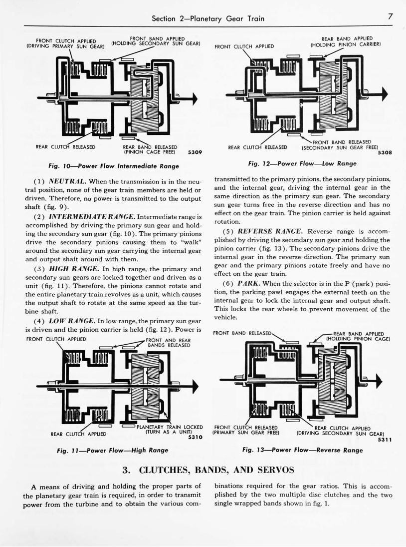
Fig. 10 Power Flow Intermediate Range
( 1 ) NEUTRAL. When the transmission is in the neu
tral position, none of the gear train members are held or
driven. Therefore, no power is transmitted to the output
shaft (fig. 9).
( 2 ) INTERMEDIATE RANGE. Intermediate range is
accomplished by driving the primary sun gear and hold
ing the secondary sun gear (fig. 10). The primary pinions
drive the secondary pinions causing them to"walk"
around the secondary sun gear carrying the internal gear
and output shaft around with them.
(3) HIGH RANGE. In high range, the primary and
secondary sun gears are locked together and driven as a
unit (fig. 11). Therefore, the pinions cannot rotate and
the entire planetary train revolves as a unit, which causes
the output shaft to rotate at the same speed as the tur
bine shaft.
(4) LOW RANGE. In low range, the primary sun gear
is driven and the pinion carrier is held (fig. 12). Power is
FRONT CLUTCH APPLIED FRONT AND REAR
BANDS RELEASED
REAR CLUTCH APPLIED
'PLANETARY TRAIN LOCKED
(TURN AS A UNIT)
5310
FRONT BAND RELEASED
REAR CLUTCH RELEASED (SECONDARY SUN GEAR FREE)
Fig. 72 Power Flow tow Range
5308
transmitted to the primary pinions, the secondary pinions,
and the internal gear, driving the internal gear in the
same direction as the primary sun gear. The secondary
sun gear turns free in the reverse direction and has no
effect on the gear train. The pinion carrier is held against
rotation.
(5) REVERSE RANGE. Reverse range is accom
plished by driving the secondary sun gear and holding the
pinion carrier (fig. 13). The secondary pinions drive the
internal gear in the reverse direction. The primary sun
gear and the primary pinions rotate freely and have no
effect on the gear train.
(6) PARK. When the selector is in the P (park) posi
tion, the parking pawl engages the external teeth on the
internal gear to lock the internal gear and output shaft.
This locks the rear wheels to prevent movement of the
vehicle.
FRONT BAND RELEASED REAR BAND APPLIED
(HOLDING PINION CAGE)
FRONT CLUTCH RELEASED
(PRIMARY SUN GEAR FREE)
REAR CLUTCH APPLIED
(DRIVING SECONDARY SUN GEAR)5311
Fig. 1 1 Power Flow High Range Fig. 73 Power Flow Reverse Range
3. CLUTCHES, BANDS, AND SERVOS
A means of driving and holding the proper parts of
the planetary gear train is required, in order to transmit
power from the turbine and to obtain the various com
binations required for the gear ratios. This is accom
plished by the two multiple disc clutches and the two
single wrapped bands shown in fig. 1.

8 Chapter IConstruction and Operation
FRONT CLUTCH
FRONT CLUTCH PISTON
TURBINE
SHAFT
FLUID PRESSURE
Fig. 14 Fronf Clutch
5589
a. Construction.
Construction of the clutches, bands, and servos is
given below.
(1) FRONT CLUTCH. The front clutch assembly
consists of the front clutch cylinder, front clutch piston,
release spring, three steel drive plates and four clutch
driven plates with composition facings (fig. 14). Three
drive and four driven clutch plates are used in all models.
The drive plates are connected to the turbine shaft. The
driven plates are connected to the primary sun gear shaft.
(2) REAR CLUTCH. The rear clutch consists of a
rear clutch drum, rear clutch piston, release spring, four
steel clutch driven plates, and four clutch drive plates
with composition facings (fig. 15). The rear clutch drive
plates are connected to the front clutch drum and the
ACCUMULATOR PISTON
\D
SPRING
5591
Fig. 16 Disassembled Rear Servo
four driven plates are connected to the secondary sun
gear. A heavy release spring is used in the rear clutch
assembly.
(3) BANDS. The front and rear bands are made of
steel and have composition linings bonded to the inside
surfaces. The front band encircles the drum of the sec
ondary sun gear assembly. One end of the band is an
chored in the transmission case and the other end is
connected to the front servo.
The rear band fits around the planetary gear assembly
drum. One end of the band contacts the end of the band
adjusting screw and the opposite end is connected to the
rear servo.
(4) FRONT SERVO. The front servo assembly con
sists of an aluminum servo body, front servo piston,
piston guide, release spring, and an actuating lever. The
inner end of the lever contacts the front servo piston stem
and the outer end contacts the front band strut.
(5 ) REAR SERVO. The rear servo assembly consists
of a cast aluminum servo body, rear servo piston, accumu
lator piston spring, accumulator piston, rear servo release
spring, and an actuating lever. The inner end of the
actuating lever contacts the accumulator piston and the
outer end engages one end of the rear band strut (fig. 16).
FRONT
CLUTCH
PISTON
FRONT
CLUTCH
FLUID PRESSURE
SECONDARY
SUN GEAR
- FLUID
PRESSURE5590
Fig. 75 Rear Clutch
h. Operation.
Operation of the clutches, bands, and servos is covered
below.
( 1 ) FRONT CLUTCH. The front clutch is operated
by fluid pressure against the front clutch piston. The pis
ton is moved against a spring washer which increases the
"apply"
force through lever action to lock the multiple
disc clutch. When the clutch is applied the primary sun
gear is locked to the turbine shaft to drive the primary
sun gear. The primary sun gear is driven in all forward
speeds. The piston is returned to the released position by
the spring washer when the fluid pressure is removed
(fig. 14).
(2) REAR CLUTCH. The rear clutch is operated byfluid pressure against the rear clutch piston. Movement
of the piston compresses the release spring and locks the
multiple disc clutch. The rear clutch drive plates are

Section 3Clutches, Bands, and Servos
splined to the front clutch drum and the driven plates
are connected to the secondary sun gear. When the rear
clutch is applied, the secondary sun gear is driven in
reverse and in the drive range high ratio. The piston is
returned to the released position by the rear clutch re
lease spring (fig. 15).
(3 ) BANDS. The front band encircles the drum of the
secondary sun gear assembly. One end of the band is
anchored against a boss in the transmission case. The
opposite end of the band engages a strut between the
band and front servo actuating lever. When fluid pres
sure is introduced into the front servo, the piston is
forced inward against the release spring to tighten the
front band around the drum. When the band is held
tightly around the drum, it prevents the secondary sun
gear from turning. The front band is applied in the inter
mediate ratio.
The rear band ?s placed around a drum attached to the
pinion carrier. One end of the rear band contacts a strut
on the inner end of the rear band adjusting screw. The
other end of the band engages the strut between the band
and the rear servo actuating lever. Fluid pressure directed
to the rear servo piston tightens the band around the
drum and prevents the pinion carrier from rotating. The
rear band is applied in the low and reverse ratios. When
the fluid pressure is removed, the rear band is released
by the rear servo return spring pressure.
(4) FRONT SERVO. The front servo piston is moved
FRONT BAND
FRONT SERVO
by fluid pressure which exerts force against the inner end
of the front servo actuating lever. Force is transmitted
through a strut between the outer end of the lever and
the end of the band to tighten the front band around the
drum. Under certain conditions, the servo is released by
directing fluid pressure to the opposite side of the piston,
assisted by release spring force. Under some conditions,
the front servo is released by spring pressure only
(fig.17).
(5) REAR SERVO. The rear servo assembly uses an
accumulator piston and spring to cushion application of
the rear band. Fluid pressure is directed to the rear servo
piston to force it inward. When the band contacts the
drum, cushioning is provided as the accumulator piston
spring is compressed. As the accumulator piston bottoms
in the rear servo piston bore, the rear band is fully ap
plied (fig. 18).
The clutches and bands are applied by pressure from
the hydraulic control system in the following combina
tions to obtain the desired gear ranges:
Ratio
Neutral
Intermediate ( 1.467 : 1 )
High (1:1)
Low (2.40:1)
Reverse (2:1)
Apply
No Clutches or Bands
Front Clutch Front Band
Front Clutch Rear Clutch
Front Clutch Rear Band
Rear Clutch Rear Band
REAR BAND
APPLY-
Fig. 17 Fronf Servo Operation
APPLY
5580
Fig. 78 Rear Servo Operation
4. CONTROL SYSTEM
A control system is provided which makes the trans
mission respond to the desires of the driver as well as to
road and speed conditions. The construction and opera
tion of this system is fully described in this section.
a. Construction.
The control system consists of a manual selector lever
for the driver, and a hydraulic control system which is
sensitive to throttle position and road speed.

10 Chapter IConstruction and Operation
CONVERTER PRESSURE VALVE CONVERTER PRESSURE VALVE SPRING
SPACER
1Wg_\ I IfJ IBM|W| U
REGULATOR IBS
\ \CONTROL PRESSURE VALVE
SLEEVE AND RETAINERCONTROL PRESSURE RETAINER
VALVE SPRING
FRONT PUMP
CHECK VALVE
SPRINGSEPARATOR PLATE
FRONT PUMP CHECK VALVE
1 1 I 1 5542
Fig. 19 O// Pressure Regulator Assembly
The manual selector lever permits the driver to select
the particular range of transmission operation desired.
Five range positions are provided: P (parking), R (re
verse), N (neutral), Dr. (drive), and Lo (low). The
selector lever, connected to the valve system by a link
age, permits remote control of the valves.
The hydraulic control system consists ofhydraulically-
operated valves, two pumps, and the connecting lines.
The valves are mounted in the control valve body, the
pressure regulator body, and the governor body. When
the pumps are operating, fluid in a sump at the bottom
of the transmission case passes, under pressure, to the
control system.
( 1 ) FRONT OIL PUMP. The front oil pump is a cres
cent-type, high-volume pump mounted on the front face
of the transmission case. A tube connects the sump to the
intake side of the pump. Impeller hub drive lugs contact
bosses on the front pump drive gear to drive the pump at
engine speeds. Fluid from the pump is directed to the
oil pressure regulator valve assembly.
(2) OIL PRESSURE REGULATOR VALVE AS
SEMBLY. The oil pressure regulator valve assembly con
sists of a cast aluminum body, control pressure regulator
valve and spring, converter pressure regulator valve and
spring, and a spring retainer (fig. 19).
A stamped-steel spring seat and stem assembly is used
at the end of the control pressure regulator valve, and a
steel sleeve is used as a guide and stop inside the con
verter pressure regulator spring. A boss, cast on the top
of the pressure regulator valve body, and a slot in the
base of the body casting are used to lock the spring re
tainer in position on the body. The control pressure regu
lator valve springs are the same for all models except the
6-cylinder car. On the 6-cylinder car, the control pressure
regulator valve spring is painted blue. The converter
regulator valve springs are painted green on all models.
(3) MANUAL CONTROL VALVE. Linkage connects
the selector arm at the steering column to the outer
manual lever on the transmission. This permits the driver
to manually move the valve to the desired driving range.
(4) SHIFT VALVES. Two shift valves are located in
the control valve assembly. The 2-3 shift valve is posi
tioned in the bore with two springs. A governor plug is
positioned against the end of the shift valve opposite the
springs. The 2-3 shift valve provides automatic shifts
from the intermediate to the high ratio.
The 2-1 shift valve fits in a bore in the control valve
assembly. A spring positions the valve in the bore. The
valve blocks the fluid passage from the manual valve to
the rear servo in the intermediate and high ratios, and
is moved to open this passage in the low and reverse
ratios with control pressure from the downshift valve.
(5) GOVERNOR VALVE. A governor assembly is
attached to the output shaft to produce governor pres
sure. Control pressure from the control valve assembly
is directed through a case passage and a tube between
the case and distributor sleeve to the governor valve.

Section 4Control System 11
The governor valve is operated by centrifugal force work
ing against control pressure on a face of the valve. Gov
ernor pressure is provided by regulating control pressure
in direct proportion to governor rotation or vehicle speed.
A tube between the distributor sleeve and the transmis
sion case is used to direct governor pressure to the con
trol valve assembly.
(6) THROTTLE VALVE. The throttle valve is posi
tioned in a bore in the control valve assembly by a spring.
Control pressure is directed to a land of the valve. The
valve is actuated by movement of the throttle lever and
downshift valve when the accelerator pedal is depressed.
As the valve is moved, control pressure is regulated to
provide throttle pressure. Throttle pressure is directed to
the shift valve plug at the spring end of the shift valve
to assist the shift valve springs to oppose governor pres
sure. Throttle pressure is also directed to the orifice
control valve and the modulator valve.
(7) ORIFICE CONTROL VALVE. The orifice con
trol valve is positioned in a bore in the control valve
assembly by a spring. During a normal high to inter
mediate ^hift with closed throttle, smooth front band
application is provided by exhausting the front servo
release fluid through a small orifice. When the same shift
occurs at open throttle, the orifice control valve, posi
tioned by throttle pressure, permits an unrestricted ex
haust of front servo release pressure, providing a rapid
front band application.
On a manual shift from intermediate to low at closed
throttle, the orifice control valve momentarily restricts
the fluid flow applying the rear servo and releasing the
front servo. This action provides a smooth rear band
engagement.
(8) DOWNSHIFT VALVE. The downshift valve is
positioned in the control valve body bore with the
throttle valve. The inner throttle lever contacts one end
of the downshift valve and the inner end contacts the
downshift valve spring. Control pressure is directed to a
land of the valve. Linkage is connected between the
accelerator pedal and throttle lever. The downshift valve
is moved to open a passage to direct fluid pressure to the
back face of the 2-3 shift valve and the 2-1 shift valve
when the accelerator pedal is depressed completely.
(9) TRANSITION VALVE. The transition valve is
positioned in a bore in the control valve body by a spring.
The function of this valve is to time the operation of the
front servo in relation to the rear servo.
Fluid flow to apply the rear band is blocked by the
transition valve until the flow to release the front band
has built up enough pressure to open the transition valve
against its spring.
When the rear band is released, the fluid is exhausted
slowly by the action of the rear servo check valve orifice
until front servo release pressure is exhausted. With front
servo release pressure gone, the transition valve is moved
by its spring and provides an unrestricted exhaust for the
rear servo fluid.
(10) LOW INHIBITOR VALVE. The low inhibitor
valve is a part of the control valve assembly. This valve
prevents a shift into low above approximately 25 m.p.h.
A spring at one end of the valve holds it in a closed
position. Passages are provided at both ends of the valve.
Governor pressure is directed to the end of the valve
opposite the spring, and fluid pressure from the manual
valve is directed to one of the lands. The valve is moved
against the spring when the vehicle speed increases to
produce enough governor pressure to overcome the spring
force, and causes the shift from low to intermediate.
(11) MODULATOR VALVE. Themodulator valve is
spring loaded and fits in a bore in the control valve assem
bly. Fluid passages are provided to direct fluid pressure
to the large end of the valve and throttle pressure is di
rected to one of the lands. Two passages from the modu
lator valve direct throttle pressure or modulated throttle
pressure to the compensator valve, depending on the posi
tion of the manual valve.
(12) COMPENSATOR VALVE. The compensator
valve is located in one of the bores of the control valve
assembly. A compensator valve spring is used between
one end of the valve and the compensator sleeve. Control
pressure is directed to a land on the valve and governor
pressure is directed to both ends of the compensator
valve. Control pressure, regulated by the compensator
valve, produces a reduced pressure called compensator
pressure which is directed to the control pressure regula
tor valve.
(13) CONVERTER PRESSURE REGULATOR
VALVE. The spring-loaded converter pressure regulator
valve is located in a bore in the pressure regulator body.
Fluid pressure exhausted from the control pressure regu
lator valve is directed to a valley of the converter regula
tor valve and to the converter. Fluid returned from the
converter is directed to a land of the valve to provide fluid
pressure in the converter regulated to a pressure below
that used in the transmission hydraulic system. Trans
mission lubrication is provided from another land of the
converter pressure regulator valve.
( 14) REAR OIL PUMP. The rear oil pump is a cres
cent-type pump driven by the transmission output shaft.
An intake tube is connected between the sump and the
intake side of the pump. A tube from the discharge side
of the rear pump is used to direct fluid pressure to the
pressure regulator assembly and control valve assembly.
A lubrication tube, connected between the pressure regu
lator body and the rear pump, provides lubrication for
the transmission.

12 Chapter IConstruction and Operation
FROM PUMP5623
Fig. 20 Control Pressure Regulator Valve Operation
b. Operation.
The automatic operation of the transmission is pro
vided by controlling the flow of fluid pressure to the com
ponents. Fluid flow needed to operate the components
and to provide the different ratios is explained here. Con
trol diagrams for all the ratios are given in Chapter Seven.
( 1 ) NEUTRAL RANGE. The front oil pump is driven
when the engine is started with the selector lever in the
N (neutral) position. Fluid pressure from the front pump
-is directed to the control pressure regulator valve. Regu
lated fluid pressure (control pressure) is directed from
the pressure regulator valve to the manual valve. In the
neutral position, control pressure is directed to the down
shift valve, throttle valve, converter, and converter pres
sure regulator valve. No fluid pressure is directed to the
CONTROL PRESSURE
GOVERNOR
PRESSURE
OUTPUT SHAFT
5573
Fig. 21 Governor Assembly
clutches or servos. Therefore, no power is delivered to
the output shaft, and the transmission is in the neutral
ratio.
Variations in pump speed from an engine idle speed
to wide open throttle would provide a wide range of
transmission operating pressures. The control pressure
regulator valve (fig. 20) regulates variable pump pres
sures to provide constant pressure for operation of the
transmission. Fluid from the pump at"A"
is directed to
the valve at "C", "D", and "E". When the pump builds
up enough hydraulic pressure at"C"
to overcome the
force of the spring, the valve moves to the position shown,
opens the port at "D", and exhausts a portion of the pump
pressure. As the pump volume varies, the valve auto
matically positions itself so that enough fluid exhauses at
port"D"
to maintain constant pressure at "B".
(2) DRIVE RANGE INTERMEDIATE RATIO.
When the selector lever is moved from the N (neutral)
position to Dr (drive), the manual valve moves to open
passages from the manual valve to the front clutch and
governor, the apply side of the front servo, and to the 2-1
and 2-3 shift valves. Control pressure to the front clutch
locks the primary sun gear to the turbine shaft. Control
pressure to the apply side of the front servo applies the
front band to hold the secondary sun gear. The 2-1 and
2-3 shift valves are held in the closed position by the
shift valve springs, and control pressure is blocked at the
shift valve lands. With the primary sun gear driven and
the secondary sun gear held, the transmission operates
in the intermediate ratio of 1.467 to 1.
(3 ) DRIVE RANGE HIGH RATIO. The shift from
the intermediate to the high ratio is accomplished when
the front servo is released and the rear clutch is applied.
This is accomplished by directing regulated control pres
sure (governor pressure) to the end of the 2-3 shift
valve. As the shift valve moves inward, passages are
uncovered to direct control pressure to the release side
of the front servo and to the rear clutch. When both
clutches are applied, the primary and secondary sun gears
are locked to the turbine shaft to provide the high ratio
of 1 to 1.
A centrifugally-operated governor is used to provide
automatic shifts from the intermediate to the high ratio
(fig. 21). Control pressure from the manual valve is
directed against a face of the governor valve. The gov
ernor valve is forced outward by centrifugal force as the
output shaft begins to rotate. Control pressure is reduced
and is regulated in direct proportion to the vehicle speed.
When enough governor pressure is provided against the
shift valve to overcome the springs, the shift valve moves
inward to uncover the passages to the release side of the
front servo and to the rear clutch.
(4) DRIVE RANGE LOW RATIO. Forced down
shifts from the high ratio to the low ratio at vehicle speeds

Section 4Control System 13
below approximately 16 m.p.h. or from the intermediate
ratio to the low ratio at speeds below 17-23 m.p.h. can be
obtained by depressing the accelerator pedal to the floor.
When the accelerator pedal is completely depressed, the
downshift valve is moved inward to open a passage to
direct control pressure to the shift valves. Control pres
sure directed to the back face of the 2-3 shift valve forces
it closed against governor pressure. Movement of the 2-3
shift valve cuts off control pressure to the rear clutch
and to the release side of the front servo.
At the same time downshift pressure is directed to the
end of the 2-1 shift valve and moves it against spring
pressure. Control pressure from the 2-1 shift valve is di
rected through a valley of the low inhibitor valve, the
closed 2-3 shift valve, and the orifice control valve to the
release side of the front servo to release the front band.
Control pressure from the closed 2-3 shift valve is also
directed through a check valve to the rear servo to apply
the rear band. When the front clutch is applied to drive
the primary sun gear and the rear band is applied to hold
the pinion carrier, the transmission operates in the low
ratio of 2.40 to 1.
Upshifts from the drive range-low ratio are accom
plished automatically. Governor pressure against the end
of the low inhibitor valve increases with vehicle speed.
At 28-34 m.p.h., governor pressure is high enough to move
the low inhibitor valve inward to cut off rear servo apply
and front servo release pressure. The front band is then
applied by front servo apply pressure, and the transmis
sion shifts from the low to the intermediate ratio. A fur
ther increase in governor pressure moves the 2-3 shift
valve inward to release the front band and apply the rear
clutch and the transmission shifts to the high ratio.
(5) LOW RANGE. The low range is provided by
moving the selector lever to the Lo (low) position.
The transmission cannot upshift when the manual valve
is in this position. In the low position, control pres
sure is directed to the front clutch and governor, through
the downshift valve to the ends of the shift valves and to
the apply side of the front servo and tothe 2-1 shift valve.
Control pressure through the downshift valve is directed
to the end of the 2-1 shift valve to move it against spring
pressure. A passage is opened from the 2-1 shift valve,
through the closed 2-3 shift valve, and orifice control
valve to the release side of the front servo. At the same
time, control pressure is directed to the rear servo to apply
the band.
Upshifts from the low range are prevented by control
pressure, from the manual valve, directed to the spring
end of the low inhibitor valve. Governor pressure on the
end of the valve, is insufficient to move the valve against
opposing control pressure. As long as front band release
and rear clutch apply pressures are present, upshifts are
prevented.
(6) REVERSE RANGE. The reverse ratio is obtained
when the manual valve is moved to the reverse position.
Control pressure to the front clutch is cut off at the
manual valve. Control pressure from the manual valve
is directed to the apply side of the front servo, and
through the 2-1 shift valve, 2-3 shift valve and orifice
control valve to the release side of the front servo and to
apply the rear servo. Control pressure from the manual
valve is also directed to the rear clutch. With the rear
band and rear clutch applied, the transmission operates in
the reverse ratio of 2 to 1.
(7) PARK. The P (park) position is provided to lock
the transmission to prevent movement of the vehicle. A
mechanical pawl is engaged with external gear teeth on
the internal gear. Control pressure from the manual valve
is directed through the downshift valve to the ends of
the 2-3 and 1-2 shift valves. Control pressure is also
directed to the apply side of the front servo and through
the 2-1 and 2-3 shift valves to the release side of the
front servo and to apply the rear servo.
SERVICE LETTER REFERENCE
Letter No. Date SubjectChanges Information
on Page No.

Chapter TWO
Maintenance and AdjustmentsSection Page
1 Transmission Fluid 14
2 Adjustments 15
The procedures needed to properly maintain and
adjust the Fordomatic transmission are given in this
chapter. These operations should be performed complete
ly and correctly for best Fordomatic performance.
1. TRANSMISSION FLUID
The transmission was filled at the factory with Auto
matic Transmission Fluid Type A. Always use this type
when adding or changing fluid as the use of improper or
inferior fluid may affect the operation of the transmission.
a. Checking Fluid Level.
Check the transmission fluid level at 1000-mile inter
vals using the following procedures:
Apply the parking brake, then place the transmission
selector lever in the N (neutral) position. Run the engine
at idle speed for about four minutes, then move the selec
tor lever to P (park). When the engine and transmission
have reached their normal operating temperatures, move
the selector lever through all the positions to make sure
that the fluid is distributed throughout the transmission.
Return the selector lever to P (park).
Raise the hood, then clean all dirt from the transmis
sion fluid level indicator cap before removing the indica
tor (fig. 1). Pull the indicator out of the tube, wipe it
clean, then insert it back in the tube. Be sure that the
indicator is pushed down all the way. Remove the indi
cator and check the fluid level. If necessary, add enough
Fig. 7 Checking Fluid Level
fluid to raise the fluid level to the full (F) mark on the
indicator.
b. Leakage Check Points.
Inspect the bottom of the floor pan at the rear of the
transmission for fluid leaks. If fluid is found here, the
extension housing rear seal is leaking and should be
replaced.
Check the speedometer cable connection at the trans
mission. Replace the rubber seal if necessary.
Inspect the governor inspection plate for leakage. In
stall a new gasket if needed.
Leakage at the oil pan gasket often can be stopped by
tightening the attaching bolts to the proper torque ( 10-13
foot-pounds). If necessary, install a new gasket.
Check the fluid filler tube connection at the trans
mission oil pan. If leakage is found here, tighten the
connection.
Check all the oil cooler fluid connections, and tighten
them if necessary.
If leakage is found at either the throttle lever shaft or
the manual lever shaft, replace either or both seals.
Inspect the two hexhead pipe plugs on each side of the
transmission case at the front. If either plug shows leak
age, tighten the plug to 7-15 foot-pounds torque. If tight
ening does not stop the leaks, replace the leaking plug.
Inspect the inside of the discharge air duct. Leakage
here may be caused by loose converter cover bolts or by
loose converter drain plugs. Check the converter cover
nuts for proper tightness (15-28 foot-pounds torque). Do
not tighten the converter cover nuts when they are hot,
as leakage may result.
Remove the two converter drain plugs with a six-point
wrench. Coat the threads with No. 3 Permatex and install
the plugs. Tighten the drain plugs to 7-10 foot-pounds
torque.
CAUTION: Fluid in the discharge air duct may be
caused by engine oil leaking past the rear main bear
ing. Be sure to determine the exact cause of the leak.
14

Section 1Transmission Fluid 15
c. Changing Transmission Fluid.
The transmission fluid should be changed and the
bands should be adjusted at 15,000-mile intervals. When
changing the fluid, use the following procedures:
Remove the converter housing lower plate, then re
move one of the converter drain plugs. Rotate the con
verter180
and remove the other drain plug. Disconnect
the fluid filler tube at the transmission oil pan. Drain the
fluid from the transmission, then remove the oil pan.
Clean the pan thoroughly, then install it on the trans
mission.
NOTE: When the same fluid is to be used again in the
transmission after repairs or band adjustments, be
sure to properly filter the fluid through a 100-mesh
screen, or its equivalent, as it drains from the transmis
sion. Filter the fluid again as it is poured back into
the transmission.
Connect the fluid filler tube to the transmission oil pan,
and tighten the connection securely. Install the drain
plugs in the converter cover, and tighten them to 7-10
foot-pounds torque. Install the converter housing lower
plate.
Add five quarts of Automatic Transmission Fluid
Type A to the transmission through the filler tube. Run
the engine at idle speed for about two minutes, then add
four more quarts of fluid. Let the engine idle until it
reaches its normal operating temperature. Do not race
the engine.
Move the selector lever through all the positions, then
place it in the P (park) position. Check the fluid level and
add enough fluid to bring the level up to the full (F)
mark on the indicator. The approximate Fordomatic re
fill capacity is 9 quarts (6-cylinder car and all trucks),
9V2 quarts (8-cylinder car), and IOV2 quarts (Thunder
bird and Police Interceptor).
2. ADJUSTMENTS
The Fordomatic transmission adjustments given in this
section should be performed in the order in which they
appear. Be sure that all specifications given here are
closely adhered to.
a. Engine Idle Speed Adjustment.
Place the selector lever in the N (neutral) position,
then start the engine. Run the engine at idle speed until
its normal operating temperature is reached.
Check the engine idle speed with a tachometer. The
correct idle speed should be 475-500 r.p.m. for the Thun
derbird and Police Interceptor engines, and 450-475
r.p.m. for all other car and truck engines. If the idle speed
is not within these limits, turn the carburetor idle adjust
ing screw until the correct idle speed is reached (fig. 2).
NOTE: // the anti-stall dashpot adjusting screw holds
the throttle open and prevents the correct idle speed
adjustment, loosen the locknut and turn the dashpot
adjusting scretv in (clockwise) until the correct idle
speed is reached.
b. Anti-Stall Dashpot Adjustment.
After the engine idle speed has been properly adjusted,
turn the ignition switch off and adjust the anti-stall dash-
pot.
Loosen the dashpot adjusting screw locknut. Hold the
throttle in the closed position, and turn the dashpot ad
justing screw out (counterclockwise) until the head of
the screw pushes the dashpot rod up to the end of its
travel (fig. 3).
Turn the dashpot adjusting screw in (clockwise) 1 V2-2
turns to obtain a clearance of 0.045-0.064 inches between
the rod and the screw head. After the adjustment has been
made, tighten the adjusting screw locknut.
c. Manual Linkage Adjustment.
With the engine turned off, disconnect the upper end
of the manual shift rod from the selector lever (fig. 4).
Position the selector lever so that the indicator is down
against the stop in the Dr (drive) position. Place the
transmission manual lever in the Dr (drive) detent (sec
ond from the bottom).
Rotate the manual shift rod clevis to obtain the short
est rod length that will permit the clevis pin to enter the
Screwdriver 5616
Fig. 2 Engine Idle Speed Adjustment 8-Cylinder

16 Chapter IIMaintenance and Adjustments
Fig. 3 Anti-Stall Dashpot Adjustment
grommet in the selector lever. Turn the clevis two addi
tional turns counterclockwise, then install the clevis pin.
Lock the clevis in place with the locknut. Check the
pointer alignment for all positions of the selector lever.
The Thunderbird selector lever is located on the tunnel
dome in front of the seat. The lever may be moved by
depressing a button on the end of the lever. The lever
positions from front to rear are P (park), R (reverse),
N (neutral), Dr (drive), and Lo (low) (fig. 5).
The manual shift rod is connected from the selector
lever to the transmission manual lever. Disconnect the
manual shift rod from the selector lever.
Position the selector so that the indicator at the quad
rant is against the stop in the Dr (drive ) position. Position
6410
Fig. 5 Selector Lever Thunderbird
the transmission manual lever in the Dr (drive) detent
(second from the front).
Adjust the length of the manual shift rod by turning
the clevis locknuts until the clevis pin enters the selector
lever. Turn the lock nuts one turn counterclockwise, then
install the clevis. Lock the clevis in place with the lock-
nuts. Check the pointer alignment for all positions of the
selector lever.
d. Starter Neutral Switch Adjustment.
Check the starter circuit in all selector lever positions.
The circuit must be open in all positions except N (neu
tral). To adjust, loosen the neutral switch to steering
column attaching screws. Position the switch so that the
starter circuit is closed when the selector lever is at N
(neutral).
e. Throttle Linkage Adjustment.
The throttle linkage used with the 6-cylinder cars (fig.
6) differs from the linkage on the 8-cylinder cars (fig. 7),
MANUAL SHIFT ROD CLEVIS MANUAL SHIFT ROD
ACCELERATOR
PEDAL
SELECTOR ARM STARTER NEUTRAL SWITCH
Fig. 4 Manual Linkage
55145628
Fig. 6 Throttle Linkage 6-Cy/inder


