
Delivering theGigafactory in Tesla Time
Using HD BIMGregory P. Luth, Ph.D., SE, SECB
Gregory P Luth & Associates, Inc.,
Santa Clara, CA

#BIMForumED© 2017 Gregory P Luth & Associates, Inc All rights reserved
o Provide motivation and rational for design practice change
o Define “High Definition BIM” (HD BIM) as opposed to “Conventional BIM”
o Provide an overview of vision for 21st century design-construct-own process
o Provide an overview of 9 case studies of illustrating the development and
evolution of structural HD BIM over the past 11 years
� Design strategies and work practice
� Shop drawing strategies and work practice
� Constructibility strategies and work practice
o Lessons Learned
o Final Thoughts
2Objectives and Outline of Presentation

#BIMForumED© 2017 Gregory P Luth & Associates, Inc All rights reserved
We believe that the best design is one in which all the important decisions
regarding, materials, means, methods, sequences, and schedules are made
during the design when all the impacts and costs project wide can be
considered and when the design itself can be altered to optimize schedule,
quality, cost and supply chain issues
In light of the potential offered by the digital revolution, the traditional
design process is an anachronism that we can no longer afford because too
many of the critical decisions are left for the construction team to sort out
after the design has been “finalized”
3Motivation and Rationale for Change

#BIMForumED© 2017 Gregory P Luth & Associates, Inc All rights reserved
High Definition Building Information Modeling (HD BIM)
HD BIM is a process utilizing a Building Information Model containing the
high level of detail and precision necessary to visualize, design, detail,
fabricate, and install all elements of a building with sufficient reliability
that the interaction of elements, the sequence of construction, and the
labor activities can be defined and planned to a level of granularity similar
to manufacturing.
This is currently achievable for the structural subsystems in a building,
but requires a change in the current standards of practice.
4HD BIM Definition

#BIMForumED© 2017 Gregory P Luth & Associates, Inc All rights reserved
HD BIM Principles
• One federated BIM model, live on the cloud, with all
disciplines visible to each other during authoring,
• Incorporates final construction knowledge and details
• Handed off to Facility Management
• Used as repository of data and knowledge for the life cycle
5HD BIM Principles

#BIMForumED© 2017 Gregory P Luth & Associates, Inc All rights reserved
20th Century Design and Construction
• Specialization produces silos of knowledge
• Litigation produces silos of responsibility
• Process produces paperwork
6

#BIMForumED© 2017 Gregory P Luth & Associates, Inc All rights reserved
21st Century Design and Construction – Virtuous Cycle
• Knowledge creates master builder renaissance
• Integrated teams and processes lead to hyper-efficiency
• Big Data provides transparent life cycle processes
7

8Conventional BIM VS HD BIM

#BIMForumED© 2017 Gregory P Luth & Associates, Inc All rights reserved
Case Study 1 – USC School of Cinematic Arts, 2006 -2010
USC School of Cinematic Arts – Phase I
9

#BIMForumED© 2017 Gregory P Luth & Associates, Inc All rights reserved
Case Study 1 – USC School of Cinematic Arts, 2006 -2010
USC seismic damage control system
Rocking concrete walls:
• Concrete substrate for facade
• Ductile linked shear walls
• Pivoting shear panels
• Replaceable steel fuse
10

#BIMForumED© 2017 Gregory P Luth & Associates, Inc All rights reserved
Case Study 1 – USC School of Cinematic Arts, 2006 -2010
Anchor Bolts
� 5 – 1” Anchor Bolts Embedded 40”
� Transfer Overturning Tension to Foundation Walls
� Steel and concrete in the same model for coordination
USC LOD
With design HD BIM vs construction HD BIM,
you get all the pieces in the same model for
coordination during design
11

#BIMForumED© 2017 Gregory P Luth & Associates, Inc All rights reserved
Case Study 1 – USC School of Cinematic Arts, 2006 -2010
MEP Coordination
USC Phase II Federated Model
Note that the architectural and MEP models are
overlaid on the structural model during authoring
These are screen shots of the structural design model
which is being used for steel shop drawings, rebar shop
drawings (by EOR), and light gage stud framing shop
drawings
Architectural Coordination
12

#BIMForumED© 2017 Gregory P Luth & Associates, Inc All rights reserved
Case Study 1 – USC School of Cinematic Arts, 2006 -2010 13

Case Study 2 – California Veterans Home 2010 - 2011
2 story steel administration
building
1 story steel maintenance
building
20 one story wood residential
“neighborhoods” comprising 1
million sq ft of managed elderly
care
Prefabrication intent thwarted
by industry inertia
14

Lateral System –
Diaphragms & Collectors
Real Construction &
Virtual ConstructionGarden Entry Truss
15Case Study 3 – Casino Hollywood, Toledo, Ohio, 2010 – 2011

#BIMForumED© 2017 Gregory P Luth & Associates, Inc All rights reserved
Case Study 3 – Casino Hollywood, Toledo, Ohio 2010 - 2011
400,000 sq ft of casino, 3100 car, 5 level, PT
parking garage. Construction document phase
started July 2010, pile driving started
September, 2010. GPLA produced all rebar shop
drawings and turned Tekla model over to steel
detailer
Design start: July 2010
Foundation start: September, 2010
Casino open: May, 2012
18 months design start to construction finish
16

Case Study 3 – Casino Hollywood, Toledo, Ohio 2010 - 2011 17

#BIMForumED© 2017 Gregory P Luth & Associates, Inc All rights reserved
“This project has elevated our BIM experience to a new level. Our
superintendent was referring to the latest model on a daily basis. He was able to
use an IPAD to bring the web accessed model out to the field and share it with the
crew. When the field crew starts asking to view the model, it gets the attention of
everyone. Even subcontractors that have never used it before were on board.”
– Ryan Bannister, Rudolph-Libbe, BIM Manager
“Ordinarily, the rebar shop drawings are detailed from documents that are a
month old and frequently changing. Keeping the field updated with information is
a challenge. On this project, the web model updates were available immediately,
so we looked at it every morning before we started work. The shop drawings,
coming directly from the EOR, were even better than the model – the best
information on the job.”
– Mike Keane, Rudolph-Libbe, General Superintendent
18Case Study 3 – Casino Hollywood, Toledo, Ohio, 2010 – 2011

Case Study 4 – Isle of Capri Casino, Cape Girardeau, Missouri 2011 - 2012 19
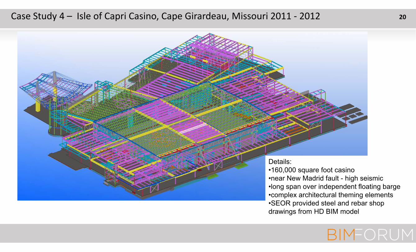
Case Study 4 – Isle of Capri Casino, Cape Girardeau, Missouri 2011 - 2012
Details:
•160,000 square foot casino
•near New Madrid fault - high seismic
•long span over independent floating barge
•complex architectural theming elements
•SEOR provided steel and rebar shop
drawings from HD BIM model
20

Case Study 4 – Isle of Capri Casino, Cape Girardeau, Missouri 2011 - 2012
Self-centering post tensioned rocking frames with fused moment trusses HiDef BIM level of detail
Slit Shear
Plate Fuse
Rocker
PT Rods
Uplift
Base
Rebar
Bond
Breaker
PT
Anchor
21

Rebar modeling and Shop Drawings by EOR accelerates the schedule and
results in higher quality end product. 2000 yd pour with 250 tons of rebar
starting at 7 pm 2 weeks after award of concrete contract. Photo at noon.
Case Study 4 – Isle of Capri Casino, Cape Girardeau, Missouri 2011 - 2012 22

#BIMForumED© 2017 Gregory P Luth & Associates, Inc All rights reserved
- 1 million square feet of light gage walls and associated roofs
- Free-standing concession and restrooms on 5 decks, design-build by GC
- GPLA design for hurricane, customized details for prefab, and prepared shop drawings
- Design, fab, install completed in 10 months avoiding $10 million LD’s
Case Study 5 – Daytona Rising, Daytona, Beach, Florida 2013 - 2014 23

#BIMForumED© 2017 Gregory P Luth & Associates, Inc All rights reserved
Case Study 5 – Daytona Rising, Daytona, Beach, Florida 2013 - 2014
Objectives:
- Prefabrication
- Reduce cost
- Aggressive schedule
Constraints:
- Layout had to be developed based on Tekla model of
field measured existing steel locations and slab
elevations
- Prefabricated panels had to accommodate all MEP
openings and hardwarePrefabricated Panelized Plumbing Walls
24
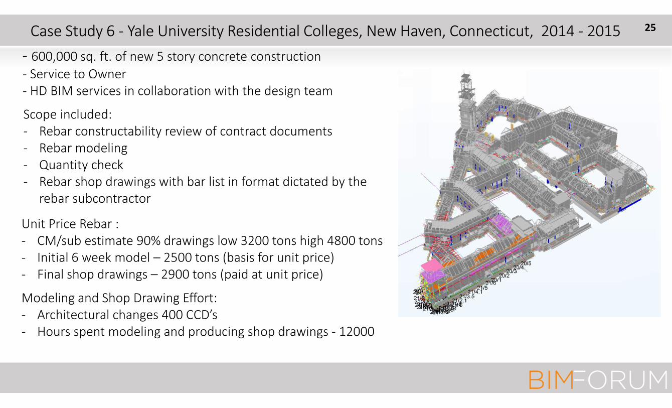
Case Study 6 - Yale University Residential Colleges, New Haven, Connecticut, 2014 - 2015
- 600,000 sq. ft. of new 5 story concrete construction
- Service to Owner
- HD BIM services in collaboration with the design team
Scope included:
- Rebar constructability review of contract documents
- Rebar modeling
- Quantity check
- Rebar shop drawings with bar list in format dictated by the
rebar subcontractor
Unit Price Rebar :
- CM/sub estimate 90% drawings low 3200 tons high 4800 tons
- Initial 6 week model – 2500 tons (basis for unit price)
- Final shop drawings – 2900 tons (paid at unit price)
Modeling and Shop Drawing Effort:
- Architectural changes 400 CCD’s
- Hours spent modeling and producing shop drawings - 12000
25

Case Study 6 - Yale University Residential Colleges, New Haven, Connecticut, 2014 - 2015 26

Case Study 6 - Yale University Residential Colleges, New Haven, Connecticut, 2014 - 2015
Example Issue:
- 15,000 lineal feet of 10x24 beams
- 2#10 top continuous and 2#9 bottom
continuous beams through 10x24 columns
- #3 @ 3” closed stirrups
The use of industry standard details resulted
in:
- Lap splices increased tonnage 50%
- Rebar cages had to be assembled in place
- Heavy hooked bars from both directions
were impossible to place in the corners
All of these problems were
eliminated by changing 1 typical
detail to improve constructability
while preserving structural
integrity
ORIGINAL DETAIL
GPLA DETAIL
27

#BIMForumED© 2017 Gregory P Luth & Associates, Inc All rights reserved
July 29, 2016 Casino Complete
Case Study 7 – Hollywood Casino Jamul, San Diego, California 2014 - 2016 28

#BIMForumED© 2017 Gregory P Luth & Associates, Inc All rights reserved
- 3-story casino above 8-story parking garage
- Partially embedded in hillside
- Rebar, stair & structural steel shop drawings
from same model by SEOR
Case Study 7 – Hollywood Casino Jamul, San Diego, California 2014 - 2016
Enabling concept: build upper 3 floors on 90
ft tall stilts first and finish casino interior
while building parking to reduce schedule by
7 months
29

#BIMForumED© 2017 Gregory P Luth & Associates, Inc All rights reserved
Case Study 7 – Hollywood Casino Jamul, San Diego, California 2014 - 2016
January 1, 2015 Excavation complete
April 3, 2015 Early walls steel erection
HD BIM Model Early Walls & Stilts
July 10, 2015 steel erection complete July 10, 2015 PT slab level 2 in progress
30

#BIMForumED© 2017 Gregory P Luth & Associates, Inc All rights reserved
Case Study 8 – Tesla Gigafactory, Sparks, Nevada, 2016 - 2017
5 Buildings, 3.8 million sq ft, 2 floors and roof, all composite steel & concrete on deck.
Gravity and lateral framing uncoupled to accelerate mill order and fabrication for 90% of steel.
First use of innovative fused strongback BRB seismic system
Schedule: start design April 15, 2016, order steel May 5, start steel fab June 6, start steel erection July 6,
complete steel erection November 15, release to process March 2017
31

Example: (for 3.4M sf!!)
• Model 3 Launch – Day 1…pre-orders climb to 400,00
• Steel Mill order: Day 48 (enough design was done to start…)
• Break Ground: Day 86
• First Pick (Steel Erection): Day 116
• MEP Initial Design: Day 155
• Room Turnover: Day 310 (10 months)
From John Vardaman,
Senior Construction Manager
September, 2016
Case Study 8 – Tesla Gigafactory, Sparks, Nevada, 2016 - 2017 32

How?
Integrated delivery – Electrical, Plumbing, Mechanical, and
Construction Administration all in house (Tesla). Where we don’t
have enough horsepower or expertise, we bring in great partners
like GPLA and have full transparency inside Tesla Motors, Inc
From John Vardaman,
September, 2016
Case Study 8 – Tesla Gigafactory, Sparks, Nevada, 2016 - 2017 33

#BIMForumED© 2017 Gregory P Luth & Associates, Inc All rights reserved
Keys to Success
• Use design strategy with interleaved activities to complement construction schedule
• Focus on design critical path – order steel ASAP, complete design & shop drawings by time
steel arrives plant, use bolted field connections, develop prefab exterior wall to weather
proof fast
‾ Develop robust lateral system to accommodate changes
‾ Develop simple but robust gravity system that can be extended and modified easily (lots
of shear studs)
‾ Uncouple lateral and gravity for design and erection
• Use integrated design, detailing, and fabrication team using same cloud-based Tekla model
with detailers under the control of the structural engineer (change management)
Case Study 8 – Tesla Gigafactory, Sparks, Nevada, 2016 - 2017 34

Key Structural Engineering Objectives & Pre-requisites
1. Get steel into the fabrication shops
a) Complete steel design, complete 3D modeling of gravity system, and
extract mill order from model
2. Supply fabrication shops with shop drawings
a) Extract shop drawings from design model
3. Submit drawings and calculations for permit
a) Complete building design, including foundations, assemble
comprehensive calculation package including documentation of global
analysis for gravity and seismic forces and design calculations for each
element of the building
Case Study 8 – Tesla Gigafactory, Sparks, Nevada, 2016 - 2017 35

Key Structural Milestones (first 50 days)
� Day 1 Phone call
� Day 7 issue Building F structural model and bid set (“Frankenset” is a
combination of new and old drawings) to fulfill corporate policy of
competitive bid
� Day 21 Issue mill order for Bldg F steel to procure (from Belgium) and get in
the shop ASAP
� Day 23 Start design buildings D’ and E’ (redirection)
� Day 30 issue mill order for Bldg D’ & E’ steel
� Day 43 issue “structure only” permit set D’ & E’ with comprehensive design
calculation package
� Day 50 Issue D’ & E ‘ foundation rebar shops
Case Study 8 – Tesla Gigafactory, Sparks, Nevada, 2016 - 2017 36
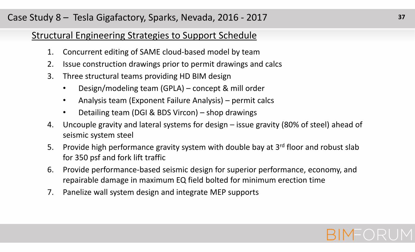
Structural Engineering Strategies to Support Schedule
1. Concurrent editing of SAME cloud-based model by team
2. Issue construction drawings prior to permit drawings and calcs
3. Three structural teams providing HD BIM design
• Design/modeling team (GPLA) – concept & mill order
• Analysis team (Exponent Failure Analysis) – permit calcs
• Detailing team (DGI & BDS Vircon) – shop drawings
4. Uncouple gravity and lateral systems for design – issue gravity (80% of steel) ahead of
seismic system steel
5. Provide high performance gravity system with double bay at 3rd floor and robust slab
for 350 psf and fork lift traffic
6. Provide performance-based seismic design for superior performance, economy, and
repairable damage in maximum EQ field bolted for minimum erection time
7. Panelize wall system design and integrate MEP supports
Case Study 8 – Tesla Gigafactory, Sparks, Nevada, 2016 - 2017 37

#BIMForumED© 2017 Gregory P Luth & Associates, Inc All rights reserved
Case Study 8 – Tesla Gigafactory, Sparks, Nevada, 2016 - 2017 38

Seismic Frames BRB-SB-KF on Exterior of Building F
Case Study 8 – Tesla Gigafactory, Sparks, Nevada, 2016 - 2017 39

Rocking Fused
Strongback Frame Field Bolted FrameRocking
Strongback Frame
Krawinkler Fuse
Case Study 8 – Tesla Gigafactory, Sparks, Nevada, 2016 - 2017 40

Details For Uncoupling Design with Robust Connections
Case Study 8 – Tesla Gigafactory, Sparks, Nevada, 2016 - 2017 41

Level of Detail in Design Model & Gravity Enabling Details
Case Study 8 – Tesla Gigafactory, Sparks, Nevada, 2016 - 2017 42

Federated Tekla Model - All
MEP Pipe Hangers Spot Cooler Support Structure
Federated Tekla model – MEP & S
Case Study 8 – Tesla Gigafactory, Sparks, Nevada, 2016 - 2017 43

Modular
Catwalk
Case Study 8 – Tesla Gigafactory, Sparks, Nevada, 2016 - 2017 44

#BIMForumED© 2017 Gregory P Luth & Associates, Inc All rights reserved
September 15, 2016 Building D’ Steel Complete
Case Study 8 – Tesla Gigafactory, Sparks, Nevada, 2016 - 2017 45

#BIMForumED© 2017 Gregory P Luth & Associates, Inc All rights reserved
Gigafactory Top Out November 7, 2016
5 Buildings
3.5 million Square Feet
32,000 tons of structural steel
2500 tons of rebar
All steel and rebar shop drawings from GPLA HD BIM model
7 months from first phone call
Case Study 8 – Tesla Gigafactory, Sparks, Nevada, 2016 - 2017 46

#BIMForumED© 2017 Gregory P Luth & Associates, Inc All rights reserved
Building G Stamping Presses and Injection Molding
Kick-off January 26, 2017
Case Study 8 – Tesla Gigafactory, Sparks, Nevada, 2016 - 2017 47

#BIMForumED© 2017 Gregory P Luth & Associates, Inc All rights reserved
48
Tesla Gigafactory Area G – Progress 5/31/2017
Case Study 8 – Tesla Gigafactory, Sparks, Nevada, 2016 - 2017

#BIMForumED© 2017 Gregory P Luth & Associates, Inc All rights reserved
49Case Study 8 – Tesla Gigafactory, Sparks, Nevada, 2016 - 2017
Tesla Gigafactory Area G – Progress
6/17/2017 – 9/5/2017 Stamping Press Pit

#BIMForumED© 2017 Gregory P Luth & Associates, Inc All rights reserved
50Case Study 8 – Tesla Gigafactory, Sparks, Nevada, 2016 - 2017
Tesla Gigafactory Area G – Progress 9/29/2017 – 11/2/2-17

#BIMForumED© 2017 Gregory P Luth & Associates, Inc All rights reserved
51Case Study 9 – Water Wind Sky, Seattle, Washington, 2017 – 2018
4 over 2 residential podium construction. All wood
members modeled. We need an interface with panel
software like Mitek to be able to automatically generate
panel drawings from Tekla model

#BIMForumED© 2017 Gregory P Luth & Associates, Inc All rights reserved
o Working in a live model with reference models for coordination is a HUGE
advantage, because it is so hard to coordinate by looking at the federated model
and then going back to your stand alone model to make revisions
o Copying a model is infeasible – its significantly faster to author a model from
scratch, which is why subcontractors can never “match” a design model
o Seeing something in a federated model is not the same as having the final
dimensions and location
o Working in the same cloud based model with detailers preparing shop drawings
contemporaneously in the same model is no only possible, its 10x more efficient
than servicing 2 models – redundant data is ALWAYS a problem
o Constructibility knowledge is gleaned from all levels of the construction team – the
knowledge you get from a PM, a superintendent, a foreman, and a laborer differs
significantly
52Lessons Learned

#BIMForumED© 2017 Gregory P Luth & Associates, Inc All rights reserved
o We REALLY REALLY need a FACILITY DATABASE that is authored jointly by all. Our
authoring software should be a two way interface with the database that permits
interdisciplinary viewing and referencing of the data.
o THE MODEL IS NOT THE DATA. The model is one way to the view the data, is extremely
useful if it is dimensionally accurate, and is of limited use if it is not dimensionally
accurate
o There are overlaps in the data that should be automatically modeled using constraints.
When a duct or pipe penetrates a slab or a beam, the duct or pipe size is not the
information the structural engineer and contractor need. The information the
contractor and engineer need is the required shape, size, and location of the hole.
“Look in the model” is not an adequate response to a request for that information.
These holes should be modeled as part of the mechanical effort. The presence of a
duct shouldn’t trigger a clash, it should trigger a hole.
o We need to move beyond clash detection
53Lessons Learned
#BIMForumED© 2017 Gregory P Luth & Associates, Inc All rights reserved
Incomplete design is the source of many of
the problems in our industry.
In light of the potential offered by the digital
revolution, the traditional design process is an
anachronism that we can no longer afford
54Conclusion
#BIMForumED© 2017 Gregory P Luth & Associates, Inc All rights reserved
Albert Einstein,
German born American Physicist
1879-1955
”Insanity is doing the same thing over and
over again and expecting different results”
Corollary 1: If you want the same results, do the
same thing.
Corollary 2: If you want something better, do
something different.
Corollary 3: Find out the best its been done before
you invent a better way – improve on the best.
55Final Thoughts

#BIMForumED© 2017 Gregory P Luth & Associates, Inc All rights reserved
56
Thank you!
Gregory P Luth & Associates, IncSanta Clara, California


