
Andrew’s Nex t Genera t ion o f
Dua l Band Antennas are Now
Des igned wi th Te le t i l t ® Compat ib i l i t y
Decibel®
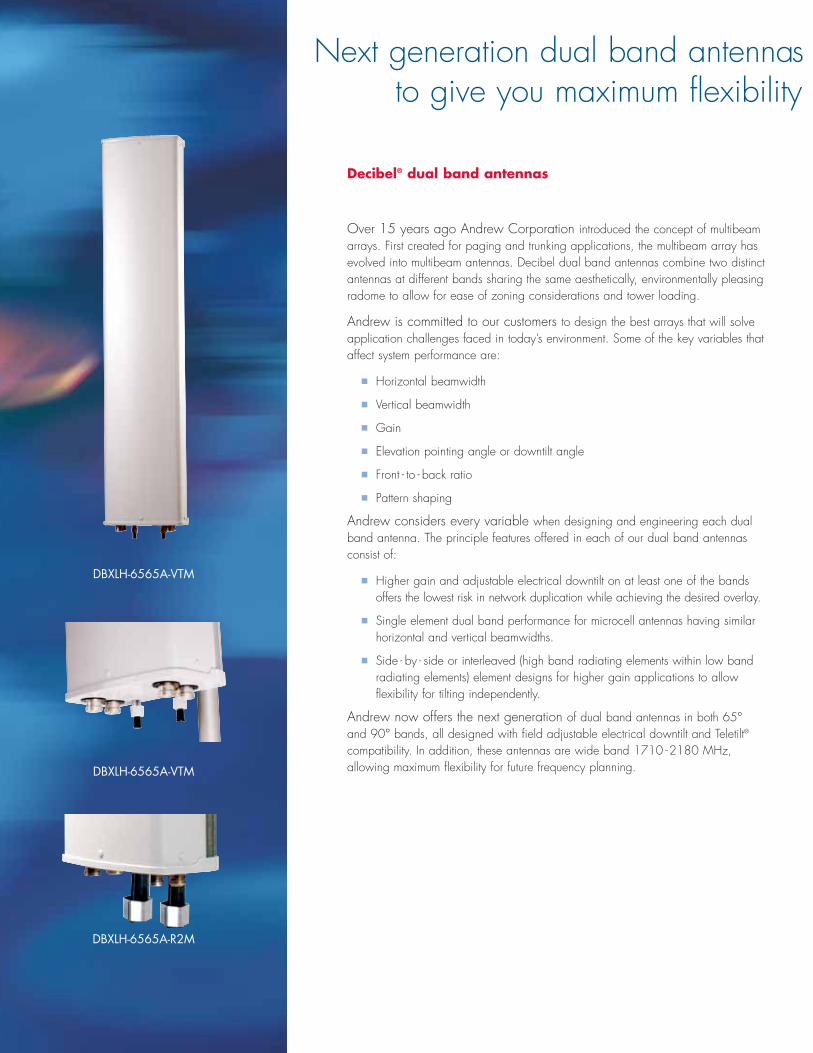
Decibel® dual band antennas
Over 15 years ago Andrew Corporation introduced the concept of multibeamarrays. First created for paging and trunking applications, the multibeam array hasevolved into multibeam antennas. Decibel dual band antennas combine two distinctantennas at different bands sharing the same aesthetically, environmentally pleasingradome to allow for ease of zoning considerations and tower loading.
Andrew is committed to our customers to design the best arrays that will solveapplication challenges faced in today’s environment. Some of the key variables thataffect system performance are:
� Horizontal beamwidth
� Vertical beamwidth
� Gain
� Elevation pointing angle or downtilt angle
� Front - to - back ratio
� Pattern shaping
Andrew considers every variable when designing and engineering each dualband antenna. The principle features offered in each of our dual band antennasconsist of:
� Higher gain and adjustable electrical downtilt on at least one of the bandsoffers the lowest risk in network duplication while achieving the desired overlay.
� Single element dual band performance for microcell antennas having similarhorizontal and vertical beamwidths.
� Side - by - side or interleaved (high band radiating elements within low bandradiating elements) element designs for higher gain applications to allow flexibility for tilting independently.
Andrew now offers the next generation of dual band antennas in both 65°and 90° bands, all designed with field adjustable electrical downtilt and Teletilt®
compatibility. In addition, these antennas are wide band 1710 -2180 MHz, allowing maximum flexibility for future frequency planning.
Next generation dual band antennasto give you maximum flexibility
DBXLH-6565A-VTM
DBXLH-6565A-VTM
DBXLH-6565A-R2M

The following model numbers represent the next generation of dual band antennas:
* Dual Band Antenna Dual Band Antenna Model Number with Factory Installed ATM200 Actuator
DBXLH - 6565A-VTM DBXLH - 6565A - R2M
DBXLH - 6565B-VTM DBXLH - 6565B - R2M
DBXLH - 6565C-VTM DBXLH - 6565C- R2M
DBXLH - 9090A-VTM DBXLH - 9090A - R2M
DBXLH - 9090B-VTM DBXLH - 9090B - R2M
DBXLH - 9090C- VTM DBXLH - 9090C-R2M
*See model specifications on the following pages.
Andrew’s Decibel® dual band model numbers are designed to tell a very specificstory, revealing specific attributes of the antenna contained within the model number.The dual band model number guide will allow for easy interpretation of the modelnumber schematic.
New Model Number Guide – Dual Band
DB X LH (A) - 90 90 A - VT M
TECHNOLOGY GROUPDB = Dual bandTB = Tri band
POLARIZATIONX = Xpol (±45˚)V = Vpol (vertical)
FREQUENCY BANDSL = 824–960 (824–896, 870–960)H = 1710–2180 (1710–1880,
1850–990, 1920–2180)
ARRAYS/OTHERA = StackedB = Side-By-SideC = With built-In diplexer
ANTENNA LENGTHA = 1.3 m (51.2 in)B = 2.0 m (78.7 in)C = 2.6 m (102.4 in)
TILT T# = Degree of fixed tiltVT = Variable electrical tiltR1 = ATC100 Teletilt®
remote control systemR2 = ATC200 Teletilt®
remote control system
MOUNTING HARDWAREM = Standard downtillt mount
Mounting Hardware
Tilt Option
Antenna Length
H Horizontal Beam Width
L Horizontal Beam Width
Arrays/Other
Frequency Bands
Polarization
Technology Group
– designed with Teletilt® compatibilityfor future frequency planning
DBXLH-9090A-VTM
DBXLH-9090A-VTM
DBXLH-9090A-R2M

Andrew Teletilt® remote control variable electrical downtilt antenna system
The Andrew Teletilt Remote Control System allows network optimization that improves coverage, lowers costs, increases revenue, and increases customersatisfaction with better call quality. Service providers can make antenna adjustmentsremotely in just minutes—without site downtime or costly tower crews.
Andrew now introduces the ATC200 Teletilt Remote Control VariableElectrical Downtilt Antenna System. The ATC200 system includes:
� Actuators (field retrofittable or factory installed to the antenna)
� Local control unit
� Portable control unit
� Control cables
� Jumpers
� Junction boxes
� Lightning protection unit
� Splitters
� Additional products
Andrew’s next generationare fully Teletilt®
ATM200-001 Actuator
ATCB-BO1 Cable
ATJB200-AO1-004
dcPower
Antenna Control UnitATC200-1000-00XXor ATC200-LITE-00XX
(Local Control Interface)
Cable AssemblyATCB-B01-006
Antenna With Factory Installed ActuatorATM200-001
Cable AssemblyATCB-B01-060
Ethernet(10 Base T)
EquipmentCabin
Hangers (68MCLICK)or Cable Ties (40417)
Cable Ground602299
Example Cable Lengths Shown
RS232(Not Supplied)
Cable AssemblyATCB-B01-002
Lightning Protection UnitATLP200-001
Cable Ground602299
Junction BoxATJB200-A01-007(Up to 32 antennas
can be daisy-chained by using multiple junction boxes.)
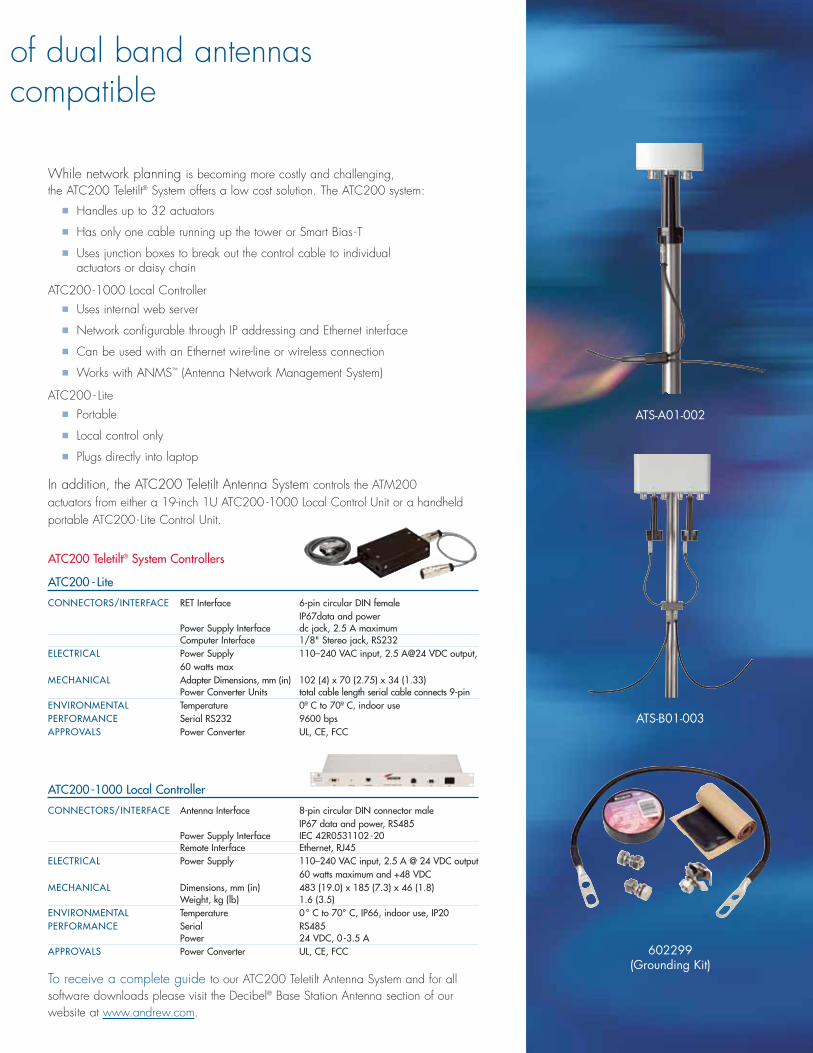
Additional Products:ATS-A01-002 Two-Way SplitterATS-B01-003 Three-Way Splitter
ATLP200-001
ATC200 Teletilt® Antenna System
To receive a complete guide to our ATC200 Teletilt Antenna System and for allsoftware downloads please visit the Decibel® Base Station Antenna section of ourwebsite at www.andrew.com.
While network planning is becoming more costly and challenging, the ATC200 Teletilt® System offers a low cost solution. The ATC200 system:
� Handles up to 32 actuators
� Has only one cable running up the tower or Smart Bias -T
� Uses junction boxes to break out the control cable to individual actuators or daisy chain
ATC200 -1000 Local Controller� Uses internal web server
� Network configurable through IP addressing and Ethernet interface
� Can be used with an Ethernet wire-line or wireless connection
� Works with ANMS™ (Antenna Network Management System)
ATC200 - Lite� Portable
� Local control only
� Plugs directly into laptop
In addition, the ATC200 Teletilt Antenna System controls the ATM200 actuators from either a 19-inch 1U ATC200 -1000 Local Control Unit or a handheldportable ATC200- Lite Control Unit.
of dual band antennas compatible
ATS-B01-003
602299(Grounding Kit)
ATC200 Teletilt® System Controllers
ATC200 -Lite
CONNECTORS/INTERFACE RET Interface 6-pin circular DIN female IP67data and power
Power Supply Interface dc jack, 2.5 A maximumComputer Interface 1/8" Stereo jack, RS232
ELECTRICAL Power Supply 110–240 VAC input, 2.5 A@24 VDC output,60 watts max
MECHANICAL Adapter Dimensions, mm (in) 102 (4) x 70 (2.75) x 34 (1.33) Power Converter Units total cable length serial cable connects 9-pin
ENVIRONMENTAL Temperature 0º C to 70º C, indoor use PERFORMANCE Serial RS232 9600 bps APPROVALS Power Converter UL, CE, FCC
ATC200-1000 Local Controller
CONNECTORS/INTERFACE Antenna Interface 8-pin circular DIN connector male IP67 data and power, RS485
Power Supply Interface IEC 42R0531102-20Remote Interface Ethernet, RJ45
ELECTRICAL Power Supply 110–240 VAC input, 2.5 A @ 24 VDC output60 watts maximum and +48 VDC
MECHANICAL Dimensions, mm (in) 483 (19.0) x 185 (7.3) x 46 (1.8) Weight, kg (lb) 1.6 (3.5)
ENVIRONMENTAL Temperature 0° C to 70° C, IP66, indoor use, IP20PERFORMANCE Serial RS485
Power 24 VDC, 0-3.5 A APPROVALS Power Converter UL, CE, FCC
ATS-A01-002

Azim
uth
Patt
ern
Elev
atio
n Pa
tter
n
Scale: 10˚ radials, 5 dB per division
DBXLH-6565A-VTMSpecifications
HORIZONTAL BEAMWIDTH
FREQUENCY RANGE
MODEL1
TYPE
RET ORDERING INFORMATION
FACTORY INSTALLED, ATM200
ELECTRICAL SPECIFICATIONS
Frequency Range (MHz)
Gain (dBi/dBd)2
Horizontal Beamwidth (Deg)
Elevation Beamwidth (Deg)
USLS (dB)3
Beam Tilt (Deg)
VSWR
PIM3 @ 2 x 20w (dbc)
Front-To-Back Ratio (dB)3
Isolation (dB)
Max. Input Power (watts)
Polarization
Connector Type
Connector Location/Qty
Impedance (ohms)
MECHANICAL SPECIFICATIONS
Length (mm/in)
Width (mm/in)
Depth (mm/in)
Net Weight (kg/lbs)
Max. Flat Plate Area (m3/ft3)
Max. Wind Load at 100 mph (N/lbf)
Max. Wind Speed (kmh/mph)
Color
Hardware Material
Std. Mounting Hardware
Std. Downtilt Hardware
65°
824–960 MHz/1710–2180 MHz
14 & 16.8 dBi/0–15° & 0–8° Tilt
DBXLH-6565A-VTM
±45° Dual Band Panel
DBXLH-6565A-R2M
824–896 870–960 1710–1880 1850–1990 1920–2180
14/11.9 14/11.9 16.5/14.4 16.8/14.7 17/14.9
68 65 65 64 63
16 15 7 6.5 6
>15 >15 >15 >15 >15
0–15 0–15 0–8 0–8 0–8
<1.5:1 <1.5:1 <1.5:1 <1.5:1 <1.5:1
-150 -150 -150 -150 -150
25 25 25 25 25
>30 >30 >30 >30 >30
250 250 200 200 200
±45° ±45° ±45° ±45° ±45°
7-16 DIN Female 7-16 DIN Female 7-16 DIN Female 7-16 DIN Female 7-16 DIN Female
Bottom (4) Bottom (4) Bottom (4) Bottom (4) Bottom (4)
50 50 50 50 50
1,295/51 1,295/51 1,295/51 1,295/51 1,295/51
266/10.5 266/10.5 266/10.5 266/10.5 266/10.5
132/5.2 132/5.2 132/5.2 132/5.2 132/5.2
12.7/28 12.7/28 12.7/28 12.7/28 12.7/28
0.16/1.7 0.16/1.7 0.16/1.7 0.16/1.7 0.16/1.7
425.2/95.6 425.2/95.6 425.2/95.6 425.2/95.6 425.2/95.6
201/125 201/125 201/125 201/125 201/125
Off White Off White Off White Off White Off White
Galvanized Steel Galvanized Steel Galvanized Steel Galvanized Steel Galvanized Steel
600899A-2 600899A-2 600899A-2 600899A-2 600899A-2
600899A-2 600899A-2 600899A-2 600899A-2 600899A-21 Same as ADFD0920-6565A-XDM2 At maximum tilt angles, gain may be slightly reduced for DBXLH-6565 series models3 Typical values
DBXLH - 6565A-VTM 824 –896 MHz
DBXLH - 6565A-VTM 1920 –2180 MHz
DBXLH-6565A-VTM 870 –960 MHz
DBXLH - 6565A-VTM 1710 –1880 MHz
DBXLH - 6565A-VTM 1850 –1990 MHz

Azim
uth
Patt
ern
Elev
atio
n Pa
tter
n
Scale: 10˚ radials, 5 dB per division
DBXLH-6565B-VTMSpecifications
HORIZONTAL BEAMWIDTH
FREQUENCY RANGE
MODEL1
TYPE
RET ORDERING INFORMATION
FACTORY INSTALLED, ATM200
ELECTRICAL SPECIFICATIONS
Frequency Range (MHz)
Gain (dBi/dBd)2
Horizontal Beamwidth (Deg)
Elevation Beamwidth (Deg)
USLS (dB)3
Beam Tilt (Deg)
VSWR
PIM3 @ 2 x 20w (dbc)
Front-To-Back Ratio (dB)3
Isolation (dB)
Max. Input Power (watts)
Polarization
Connector Type
Connector Location/qty
Impedance (ohms)
MECHANICAL SPECIFICATIONS
Length (mm/in)
Width (mm/in)
Depth (mm/in)
Net Weight (kg/lbs)
Max. Flat Plate Area (m3/ft3)
Max. Wind Load at 100 mph (N/lbf)
Max. Wind Speed (kmh/mph)
Color
Hardware Material
Std. Mounting Hardware
Std. Downtilt Hardware
65°
824–960 MHz/1710–2180 MHz
15.5 & 18.2 dBi/0–10° & 0–6° Tilt
DBXLH-6565B-VTM
±45° Dual Band Panel
DBXLH-6565B-R2M
824–896 870–960 1710–1880 1850–1990 1920–2180
15.5/13.4 16/13.9 17.8/15.7 18.2/16.1 18.3/16.2
68 65 65 64 63
10.5 10 5 4.8 4.6
>15 >15 >15 >15 >15
0–10 0–10 0–6 0–6 0–6
<1.5:1 <1.5:1 <1.5:1 <1.5:1 <1.5:1
-150 -150 -150 -150 -150
25 25 25 25 25
>30 >30 >30 >30 >30
250 250 200 200 200
±45° ±45° ±45° ±45° ±45°
7-16 DIN Female 7-16 DIN Female 7-16 DIN Female 7-16 DIN Female 7-16 DIN Female
Bottom (4) Bottom (4) Bottom (4) Bottom (4) Bottom (4)
50 50 50 50 50
1,935/76.2 1,935/76.2 1,935/76.2 1,935/76.2 1,935/76.2
266/10.5 266/10.5 266/10.5 266/10.5 266/10.5
132/5.2 132/5.2 132/5.2 132/5.2 132/5.2
19/42 19/42 19/42 19/42 19/42
0.33/3.6 0.33/3.6 0.33/3.6 0.33/3.6 0.33/3.6
782.8/176 782.8/176 782.8/176 782.8/176 782.8/176
201/125 201/125 201/125 201/125 201/125
Off White Off White Off White Off White Off White
Galvanized Steel Galvanized Steel Galvanized Steel Galvanized Steel Galvanized Steel
600899A-2 600899A-2 600899A-2 600899A-2 600899A-2
600899A-2 600899A-2 600899A-2 600899A-2 600899A-21 Same as ADFD0920-6565B-XDM2 At maximum tilt angles, gain may be slightly reduced for DBXLH series models3 Typical values
DBXLH - 6565B-VTM 824–896 MHz
DBXLH- 6565B-VTM 1920 –2180 MHz
DBXLH - 6565B-VTM 870–960 MHz
DBXLH - 6565B-VTM 1710 –1880 MHz
DBXLH - 6565B-VTM 1850 –1990 MHz
Azim
uth
Patt
ern
Elev
atio
n Pa
tter
n
Scale: 10˚ radials, 5 dB per division
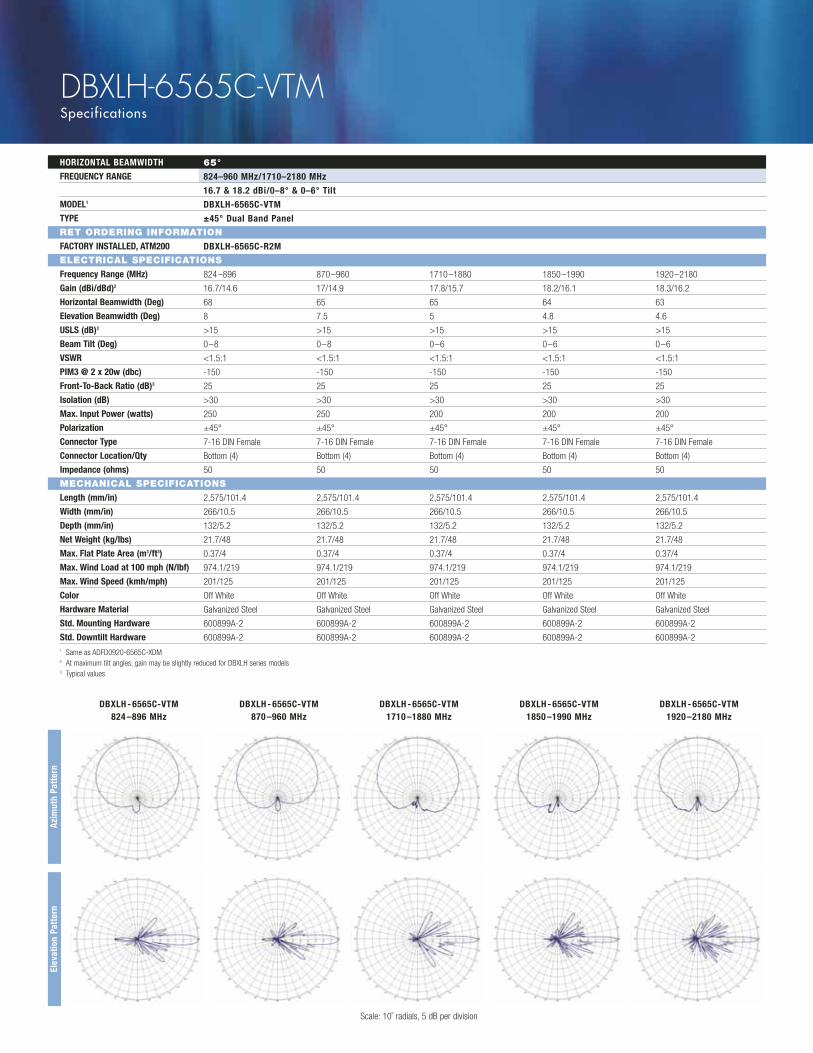
DBXLH-6565C-VTMSpecifications
1 Same as ADFD0920-6565C-XDM2 At maximum tilt angles, gain may be slightly reduced for DBXLH series models3 Typical values
DBXLH - 6565C-VTM 824 –896 MHz
DBXLH - 6565C-VTM 1920 –2180 MHz
DBXLH - 6565C-VTM 870 –960 MHz
DBXLH - 6565C-VTM 1710 –1880 MHz
DBXLH - 6565C-VTM 1850 –1990 MHz
HORIZONTAL BEAMWIDTH
FREQUENCY RANGE
MODEL1
TYPE
RET ORDERING INFORMATION
FACTORY INSTALLED, ATM200
ELECTRICAL SPECIFICATIONS
Frequency Range (MHz)
Gain (dBi/dBd)2
Horizontal Beamwidth (Deg)
Elevation Beamwidth (Deg)
USLS (dB)3
Beam Tilt (Deg)
VSWR
PIM3 @ 2 x 20w (dbc)
Front-To-Back Ratio (dB)3
Isolation (dB)
Max. Input Power (watts)
Polarization
Connector Type
Connector Location/Qty
Impedance (ohms)
MECHANICAL SPECIFICATIONS
Length (mm/in)
Width (mm/in)
Depth (mm/in)
Net Weight (kg/lbs)
Max. Flat Plate Area (m3/ft3)
Max. Wind Load at 100 mph (N/lbf)
Max. Wind Speed (kmh/mph)
Color
Hardware Material
Std. Mounting Hardware
Std. Downtilt Hardware
65°
824–960 MHz/1710–2180 MHz
16.7 & 18.2 dBi/0–8° & 0–6° Tilt
DBXLH-6565C-VTM
±45° Dual Band Panel
DBXLH-6565C-R2M
824–896 870–960 1710–1880 1850–1990 1920–2180
16.7/14.6 17/14.9 17.8/15.7 18.2/16.1 18.3/16.2
68 65 65 64 63
8 7.5 5 4.8 4.6
>15 >15 >15 >15 >15
0–8 0–8 0–6 0–6 0–6
<1.5:1 <1.5:1 <1.5:1 <1.5:1 <1.5:1
-150 -150 -150 -150 -150
25 25 25 25 25
>30 >30 >30 >30 >30
250 250 200 200 200
±45° ±45° ±45° ±45° ±45°
7-16 DIN Female 7-16 DIN Female 7-16 DIN Female 7-16 DIN Female 7-16 DIN Female
Bottom (4) Bottom (4) Bottom (4) Bottom (4) Bottom (4)
50 50 50 50 50
2,575/101.4 2,575/101.4 2,575/101.4 2,575/101.4 2,575/101.4
266/10.5 266/10.5 266/10.5 266/10.5 266/10.5
132/5.2 132/5.2 132/5.2 132/5.2 132/5.2
21.7/48 21.7/48 21.7/48 21.7/48 21.7/48
0.37/4 0.37/4 0.37/4 0.37/4 0.37/4
974.1/219 974.1/219 974.1/219 974.1/219 974.1/219
201/125 201/125 201/125 201/125 201/125
Off White Off White Off White Off White Off White
Galvanized Steel Galvanized Steel Galvanized Steel Galvanized Steel Galvanized Steel
600899A-2 600899A-2 600899A-2 600899A-2 600899A-2
600899A-2 600899A-2 600899A-2 600899A-2 600899A-2
Azim
uth
Patt
ern
Elev
atio
n Pa
tter
n
Scale: 10˚ radials, 5 dB per division
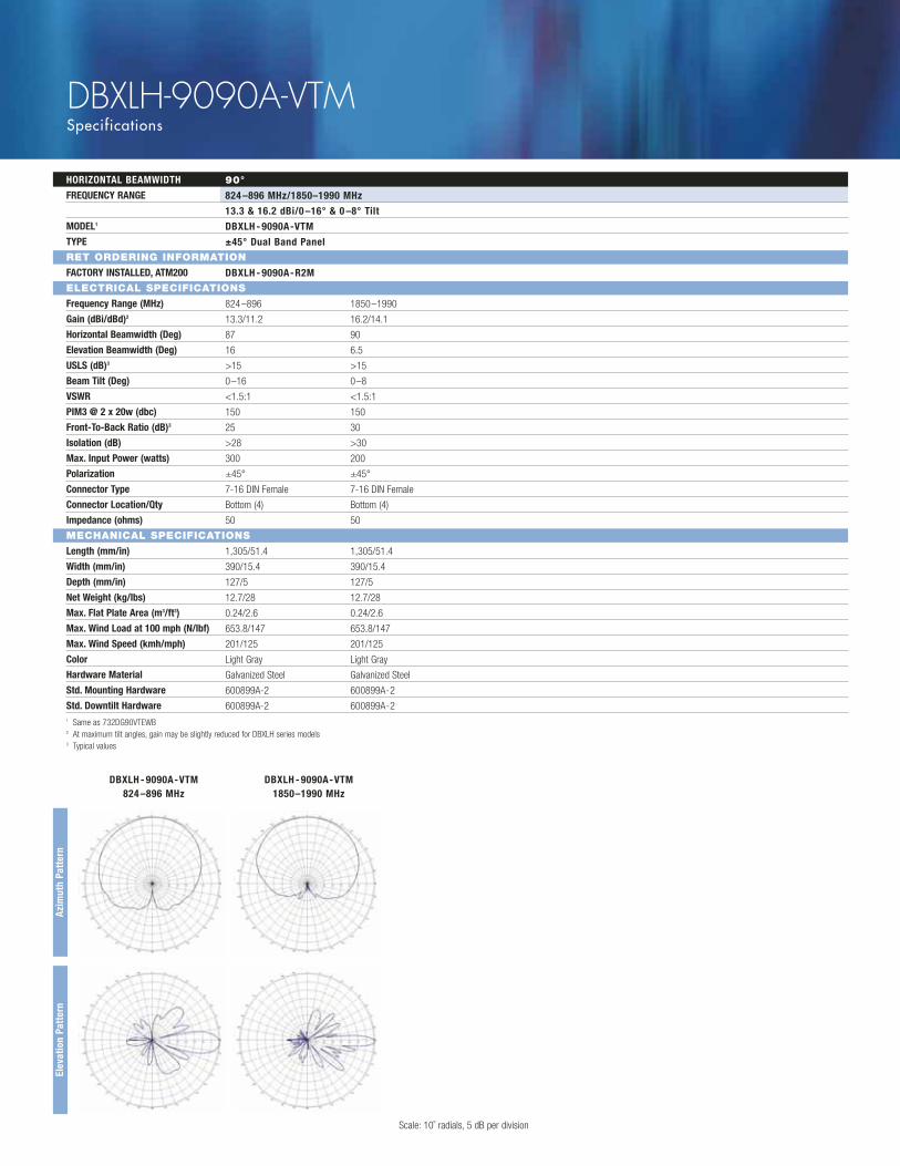
DBXLH-9090A-VTMSpecifications
HORIZONTAL BEAMWIDTH
FREQUENCY RANGE
MODEL1
TYPE
RET ORDERING INFORMATION
FACTORY INSTALLED, ATM200
ELECTRICAL SPECIFICATIONS
Frequency Range (MHz)
Gain (dBi/dBd)2
Horizontal Beamwidth (Deg)
Elevation Beamwidth (Deg)
USLS (dB)3
Beam Tilt (Deg)
VSWR
PIM3 @ 2 x 20w (dbc)
Front-To-Back Ratio (dB)3
Isolation (dB)
Max. Input Power (watts)
Polarization
Connector Type
Connector Location/Qty
Impedance (ohms)
MECHANICAL SPECIFICATIONS
Length (mm/in)
Width (mm/in)
Depth (mm/in)
Net Weight (kg/lbs)
Max. Flat Plate Area (m3/ft3)
Max. Wind Load at 100 mph (N/lbf)
Max. Wind Speed (kmh/mph)
Color
Hardware Material
Std. Mounting Hardware
Std. Downtilt Hardware
90°
824 –896 MHz/1850–1990 MHz
13.3 & 16.2 dBi/0 –16° & 0 –8° Tilt
DBXLH - 9090A-VTM
±45° Dual Band Panel
DBXLH - 9090A-R2M
824–896 1850–1990
13.3/11.2 16.2/14.1
87 90
16 6.5
>15 >15
0–16 0–8
<1.5:1 <1.5:1
150 150
25 30
>28 >30
300 200
±45° ±45°
7-16 DIN Female 7-16 DIN Female
Bottom (4) Bottom (4)
50 50
1,305/51.4 1,305/51.4
390/15.4 390/15.4
127/5 127/5
12.7/28 12.7/28
0.24/2.6 0.24/2.6
653.8/147 653.8/147
201/125 201/125
Light Gray Light Gray
Galvanized Steel Galvanized Steel
600899A-2 600899A-2
600899A-2 600899A-21 Same as 732DG90VTEWB2 At maximum tilt angles, gain may be slightly reduced for DBXLH series models3 Typical values
DBXLH - 9090A-VTM 824 –896 MHz
DBXLH - 9090A-VTM 1850–1990 MHz
Azim
uth
Patt
ern
Elev
atio
n Pa
tter
n
Scale: 10˚ radials, 5 dB per division
DBXLH-9090B-VTMSpecifications
HORIZONTAL BEAMWIDTH
FREQUENCY RANGE
MODEL1
TYPE
RET ORDERING INFORMATION
FACTORY INSTALLED, ATM200
ELECTRICAL SPECIFICATIONS
Frequency Range (MHz)
Gain (dBi/dBd)2
Horizontal Beamwidth (Deg)
Elevation Beamwidth (Deg)
USLS (dB)3
Beam Tilt (Deg)
VSWR
PIM3 @ 2 x 20w (dbc)
Front-To-Back Ratio (dB)3
Isolation (dB)
Max. Input Power (watts)
Polarization
Connector Type
Connector Location/Qty
Impedance (ohms)
MECHANICAL SPECIFICATIONS
Length (mm/in)
Width (mm/in)
Depth (mm/in)
Net Weight (kg/lbs)
Max. Flat Plate Area (m3/ft3)
Max. Wind Load at 100 mph (N/lbf)
Max. Wind Speed (kmh/mph)
Color
Hardware Material
Std. Mounting Hardware
Std. Downtilt Hardware
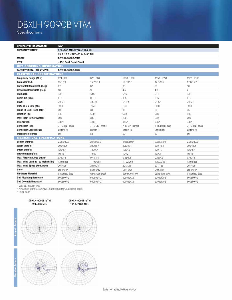
90°
824 –960 MHz/1710 –2180 MHz
15 & 17.8 dBi/0–8° & 0–5° Tilt
DBXLH-9090B-VTM
±45° Dual Band Panel
DBXLH-9090B-R2M
824–896 870–960 1710–1880 1850–1990 1920–2180
15/12.9 15.2/13.1 17.6/15.5 17.8/15.7 17.8/15.7
87 87 90 90 90
10 9 4.5 4.3 4
>15 >15 >15 >15 >15
0–8 0–8 0–5 0–5 0–5
<1.5:1 <1.5:1 <1.5:1 <1.5:1 <1.5:1
-150 -150 -150 -150 -150
30 30 35 35 35
>30 >30 >30 >30 >30
300 300 200 200 200
±45° ±45° ±45° ±45° ±45°
7-16 DIN Female 7-16 DIN Female 7-16 DIN Female 7-16 DIN Female 7-16 DIN Female
Bottom (4) Bottom (4) Bottom (4) Bottom (4) Bottom (4)
50 50 50 50 50
2,055/80.9 2,055/80.9 2,055/80.9 2,055/80.9 2,055/80.9
390/15.4 390/15.4 390/15.4 390/15.4 390/15.4
120/4.7 120/4.7 120/4.7 120/4.7 120/4.7
19/42 19/42 19/42 19/42 19/42
0.45/4.8 0.45/4.8 0.45/4.8 0.45/4.8 0.45/4.8
1,192/268 1,192/268 1,192/268 1,192/268 1,192/268
201/125 201/125 201/125 201/125 201/125
Light Gray Light Gray Light Gray Light Gray Light Gray
Galvanized Steel Galvanized Steel Galvanized Steel Galvanized Steel Galvanized Steel
600899A-2 600899A-2 600899A-2 600899A-2 600899A-2
600899A-2 600899A-2 600899A-2 600899A-2 600899A-21 Same as 736DG90VTEWB2 At maximum tilt angles, gain may be slightly reduced for DBXLH series models3 Typical values
DBXLH-9090B-VTM 824–896 MHz
DBXLH-9090B-VTM 1710–2180 MHz
Azim
uth
Patt
ern
Elev
atio
n Pa
tter
n
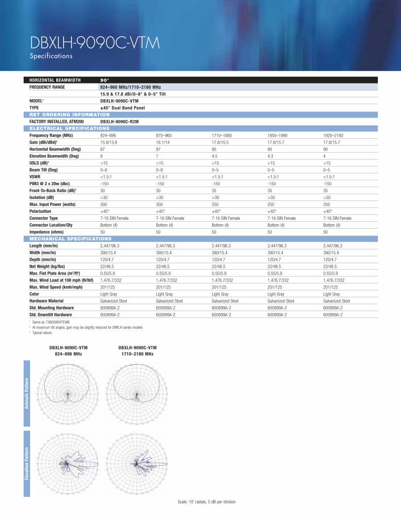
Scale: 10˚ radials, 5 dB per division
DBXLH-9090C-VTMSpecifications
HORIZONTAL BEAMWIDTH
FREQUENCY RANGE
MODEL1
TYPE
RET ORDERING INFORMATION
FACTORY INSTALLED, ATM200
ELECTRICAL SPECIFICATIONS
Frequency Range (MHz)
Gain (dBi/dBd)2
Horizontal Beamwidth (Deg)
Elevation Beamwidth (Deg)
USLS (dB)3
Beam Tilt (Deg)
VSWR
PIM3 @ 2 x 20w (dbc)
Front-To-Back Ratio (dB)3
Isolation (dB)
Max. Input Power (watts)
Polarization
Connector Type
Connector Location/Qty
Impedance (ohms)
MECHANICAL SPECIFICATIONS
Length (mm/in)
Width (mm/in)
Depth (mm/in)
Net Weight (kg/lbs)
Max. Flat Plate Area (m3/ft3)
Max. Wind Load at 100 mph (N/lbf)
Max. Wind Speed (kmh/mph)
Color
Hardware Material
Std. Mounting Hardware
Std. Downtilt Hardware
90°
824–960 MHz/1710–2180 MHz
15.9 & 17.8 dBi/0–8° & 0–5° Tilt
DBXLH-9090C-VTM
±45° Dual Band Panel
DBXLH-9090C-R2M
824–896 870–960 1710–1880 1850–1990 1920–2180
15.9/13.8 16.1/14 17.6/15.5 17.8/15.7 17.8/15.7
87 87 90 90 90
8 7 4.5 4.3 4
>15 >15 >15 >15 >15
0–8 0–8 0–5 0–5 0–5
<1.5:1 <1.5:1 <1.5:1 <1.5:1 <1.5:1
-150 -150 -150 -150 -150
30 30 35 35 35
>30 >30 >30 >30 >30
300 300 250 250 250
±45° ±45° ±45° ±45° ±45°
7-16 DIN Female 7-16 DIN Female 7-16 DIN Female 7-16 DIN Female 7-16 DIN Female
Bottom (4) Bottom (4) Bottom (4) Bottom (4) Bottom (4)
50 50 50 50 50
2,447/96.3 2,447/96.3 2,447/96.3 2,447/96.3 2,447/96.3
390/15.4 390/15.4 390/15.4 390/15.4 390/15.4
120/4.7 120/4.7 120/4.7 120/4.7 120/4.7
22/48.5 22/48.5 22/48.5 22/48.5 22/48.5
0.55/5.9 0.55/5.9 0.55/5.9 0.55/5.9 0.55/5.9
1,476.7/332 1,476.7/332 1,476.7/332 1,476.7/332 1,476.7/332
201/125 201/125 201/125 201/125 201/125
Light Gray Light Gray Light Gray Light Gray Light Gray
Galvanized Steel Galvanized Steel Galvanized Steel Galvanized Steel Galvanized Steel
600899A-2 600899A-2 600899A-2 600899A-2 600899A-2
600899A-2 600899A-2 600899A-2 600899A-2 600899A-21 Same as 738DG90VTEWB2 At maximum tilt angles, gain may be slightly reduced for DBKLH series models3 Typical values
DBXLH-9090C-VTM 824–896 MHz
DBXLH-9090C-VTM 1710–2180 MHz
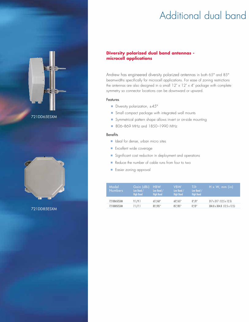
Diversity polarized dual band antennas - microcell applications
Andrew has engineered diversity polarized antennas in both 65° and 85°beamwidths specifically for microcell applications. For ease of zoning restrictionsthe antennas are also designed in a small 12" x 12" x 4" package with completesymmetry so connector locations can be downward or upward.
Features
� Diversity polarization, ±45°
� Small compact package with integrated wall mounts
� Symmetrical pattern shape allows invert or on-side mounting
� 806–869 MHz and 1850–1990 MHz
Benefits
� Ideal for dense, urban micro sites
� Excellent wide coverage
� Significant cost reduction in deployment and operations
� Reduce the number of cable runs from four to two
� Easier zoning approval
Additional dual band
721DD65ESXM
721DD85ESXM
Model Gain (dBi) HBW VBW Tilt H x W, mm (in) Numbers Low Band / Low Band / Low Band / Low Band /
High Band High Band High Band High Band
721DD65ESXM 9.1/9.1 65°/60° 60°/65° 0°/0° 317 x 317 (12.5 x 12.5)
721DD85ESXM 7.1/7.1 85°/85° 85°/85° 0°/0° 304.8 x 304.8 (12.5 x 12.5)

Vertically polarized dual band antennas
Andrew has engineered vertically polarized antennas in 60°, 65°, and 90°beamwidths. For ease of zoning restrictions not only do these antennas meet thedual band specifications, with arrays of 806–896 MHz for the low band frequencyand 1850 –1990 MHz for the high band frequency, they are also designed in aslender package.
Features
� Dual band Cellular/PCS
� Vertically polarized, both bands
� Field adjustable electrical downtilt on cellular band (V – model numbers)
� PCS array features superior USLS and NullFill
Benefits
� Minimizes risks when overlaying PCS band by allowing operators to matchexisting cellular coverage
� Allows simple integration of TMA systems to improve coverage
� Significant cost reduction in deployment and operations
antenna solutions
774G90V1ESXM
778X105M85V1
Model Gain (dBi) HBW VBW Tilt H x W, mm (in)Numbers Low Band / Low Band / Low Band / Low Band /
High Band High Band High Band High Band
744G65V1ASXM 15.1/16.8 65°/65° 16°/8° Var. 0 –16°/1° 1219 x 330 (48 x 13)
DB772G65ESXM 12.6/14.6 65°/65° 30°/15° 0°/0° 610 x 305 (24 x 12)
DB774G60ESXM 15.6/17.8 60°/60° 15°/7° 0°/0° 1219 x 318 (48 x 12.5)
774G80V1ESXM 14.1/16.3 80°/80° 15°/8° Var. 0 –10°/2° 1219 x 330 (48 x 13)
DB774G90ESXM 14/17 90°/90° 15°/7° 0°/0° 1219 x 254 (48 x 10)
774G90V1ESXM 13.8/16.1 90°/90° 14.5°/8° Var. 0 –10°/2° 1219 x 330 (48 x 13)
775G90V1ESXM 14.1/17.1 90°/90° 15°/6° Var. 0–10°/2° 1524 x 330 (60 x 13)
778G90VTAXM 16.1/19.1 90°/90° 8°/5° Var. 0–10°/Var.0–10° 2438 x 356 (96 x 14)
DB778G90ASXM 16.7/17.7 90°/85° 7°/6° 0°/0° 2438 x 356 (96 x 14)
778X105M85V1 16.2/16.8 105°/85° 7.5°/7° 0°/Var.0°–7° 2438 x 280 (96 x 11)

Indoor/Outdoor diplexer for dual-band combining of 806–960 MHz and 1710–2170 MHz
The Andrew Crossband Coupler combines signals from wireless systemsoperating in the 806 –960 MHz bands with signals from systems operating in the 1710–2170 MHz bands onto a common feeder cable.
These couplers use unique suspended stripline printed circuit board technology to provide extremely low insertion loss and high power handling capability in a compact, rugged, weatherproof housing. Sealing gaskets provide protection frommoisture ingress at all interfaces.
The Andrew Crossband Coupler 641280 product family features extremely lowinsertion loss (0.10 dB @ 806 –960 MHz and 0.15 dB @ 1710 –2170 MHz). A minimum 47 dB isolation is provided between output ports.
These couplers feature precision 7-16 DIN female connectors and an externalgrounding stud for lightning protection purposes. A mounting bracket and two band clamps are provided for quick deployment and installation. These units arestackable and do not require additional spacer hardware.
The Andrew Crossband Coupler product family is also available in different dcblock and dc bypass versions. This feature allows full compatibility with systems requiring tower mount amplifiers. The internal dc block versions utilize a distributed element dc block design, which provides lower insertion loss and better reliabilitythan dc block designs that contain ceramic dc blocking capacitors.
Features
� Novel stripline printed circuit board
� Extremely low insertion loss
� Moisture protection
� Stackable
� Mounting bracket and external grounding stud provided
� Integrated dc block/bypass versions available
Extremely low insertion loss and highpower handling capability.
dc Characteristics dc Characteristicsbetween Port 3 between Port 3 & Port 2 & Port 1
Part Number Application (806-960MHz) (1710-2170MHz)
641280-DF Indoor/Outdoor Bypass (5 amps) Bypass (5 amps) 641280-DF-9-DCB Indoor/Outdoor Blocked Bypass (5 amps)
641280
ELECTRICAL Insertion Loss, (port #2–port #3) 0.15 dB maximum, 0.10 dB typical (806–960 MHz)
(port #1–port #3) 0.20 dB maximum, 0.15 dB typical (1710–2160 MHz) (port #1–port #3) 0.30 dB maximum, 0.15 dB typical (2160–2170 MHz)
Return Loss, (port #2–port #3) 20 dB minimum, 23 dB typical (806–960 MHz) (port #1–port #3) 20 dB minimum, 23 dB typical (1710–2160 MHz) (port #1–port #3) 16 dB minimum, 19 dB typical (2160–2170 MHz)
Isolation, (port #1–port #3) 47 dB minimum, 50 dB typical (806–960 MHz) (port #2–port #3) 47 dB minimum, 50 dB typical (1710–2170 MHz)
Maximum Power Simultaneous operation of 500W CW (806–960) & 275 W CW (1710–2170)
Peak Power (PEP) Rating 12 kW (806–960 MHz), 6 kW (1710–2170 MHz) dc Breakdown 4000 volts (center conductor to ground) Lightning Protection 15 kA 8x20 center conductor, 50 kA 8x20 outer conductor Passive IMD, (2 x 43 dBm carriers) -153 dBc typical
ENVIRONMENTAL Operating Temperature -40° C to +65° C Moisture Resistance IP68 (housing includes weatherproof
watertight gaskets) Vibration IEC 68-2-6 (10-2000 Hz sinusoidal
amplitude 3 planes) Mechanical Shock IEC 68-2-27, 50 g Salt Fog IEC 68-2-11, (336 hrs) Solar Radiation IEC 68-2-5 Thermal Shock IEC 68-2-14 Humidity IEC 68-2-30 Weight kg (lbs) 1.95 (4.3)
with bracket 2.54 (5.6)
Specifications for Andrew Crossband Coupler Model 641280 Product Family
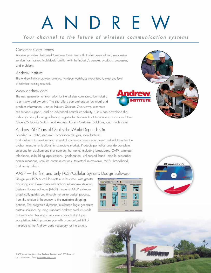
Customer Care TeamsAndrew provides dedicated Customer Care Teams that offer personalized, responsive
service from trained individuals familiar with the industry’s people, products, processes,
and problems.
Andrew InstituteThe Andrew Institute provides detailed, hands-on workshops customized to meet any level
of technical training required.
www.andrew.comThe next generation of information for the wireless communication industry
is at www.andrew.com. The site offers comprehensive technical and
product information, unique Industry Solution Overviews, extensive
self-service support, and an advanced search capability. Users can download the
industry’s best planning software, register for Andrew Institute courses, access real time
Orders/Shipping Status, read Andrew Access Customer Solutions, and much more.
Andrew: 60 Years of Quality the World Depends OnFounded in 1937, Andrew Corporation designs, manufactures,
and delivers innovative and essential communications equipment and solutions for the
global telecommunications infrastructure market. Products portfolios provide complete
solutions for applications that connect the world, including broadband CATV, wireless
telephone, in-building applications, geolocation, unlicensed band, mobile subscriber
communications, satellite communications, terrestrial microwave, WiFi, broadband,
and many others.
AASP — the first and only PCS/Cellular Systems Design SoftwareDesign your PCS or cellular system in less time, with greater
accuracy, and lower costs with advanced Andrew Antenna
Systems Planner software (AASP). Powerful AASP software
graphically guides you through the entire design process,
from the choice of frequency to the available shipping
options. The program’s dynamic, rule-based logic generates
custom solutions by using standard Andrew products while
automatically checking component compatibility. Upon
completion, AASP provides you with a customized bill of
materials of the Andrew parts necessary for the system.
AASP is available on the Andrew Powertools™ CD-Rom or as a download from www.andrew.com
A N D R E WYo u r c h a n n e l t o t h e f u t u r e o f w i r e l e s s c o m m u n i c a t i o n s y s t e m s

All designs, specifications, and availabilities of products and services presented in this bulletin are subject to change without notice.
BR-100354.1-EN (4/05)©2005 Andrew Corporation, Orland Park, IL 60462 USAPrinted in the USA
ANDREW CORPORATION
2601 Telecom Parkway Richardson, TX 75082-3521
Orders: 800.676.5342 or 214.631.0310
Fax: 800.229.4706 or 214.631.4706
www.andrew.com
800.676.5342


