
DESCRIPTIONFIREYE® Series D40-41 Burner Management Controls provide ignition and flame failure protec-tion for manually started oil or gas burners. Plug-in Amplifier Modules permit the selection of ultra-violet, repetitive self-check ultra-violet, AUTOCHECK infrared, or rectification methods of flamedetection. The control system includes a safe start check, effective on each start. If flame signal(real or simulated) is detected, the unit cannot be started. For increased safety and reliability, Fireye72D1R3 AUTOCHECK infrared amplifier (using the pulsing flame signal) and 72DUVS ultravioletamplifier (using a scanner shutter) check the function of the flame detecting system for componentfailure during each burner firing cycle. Meter test jacks on each amplifier module provide flame signalreadout with a DC voltmeter. Flame failure response time is four seconds (max.). When amplifier moduleswith T suffix are used, the flame failure response time is reduced to one second (max.).
The control provides three SPDT and one SPNO load switches for external loads and starting cir-cuits. Fireye D40-41 Burner Management controls may be adapted to a simple control system or asa building block with auxiliary devices to provide additional functions.
SPECIFICATIONSSupply Voltage:
D40-120V (Min. 102V: Max. 132V) 50/60 Hz.D41-230V (Min. 196V: Max. 253V) 50/60 Hz.
Power Consumption (Operating): 20 VA.Maximum Simultaneous Connected Load: 2000 VA.Ambient limits: Max. Min.
Control-Amplifier 140º F (60º C) - 40º F (-40º C)UV1A-UV2-UV8A-UV90 Scanner 200º F (93º C) - 40º F (-40º C)45UV5 Scanner 200º F (93º C) - 40º F (-40º C)48PT2 Scanner 140º F (60º C) - 40º F (-40º C)69ND1 Flame Rod (Tip 2460º F) 1500º F (816º C) - 40º F (-40º C)
D-4041JULY 8, 2013
SOLID STATEBurner Management
ControlsSERIES D40-41
70D41 ONLY 70D40 ONLY
2
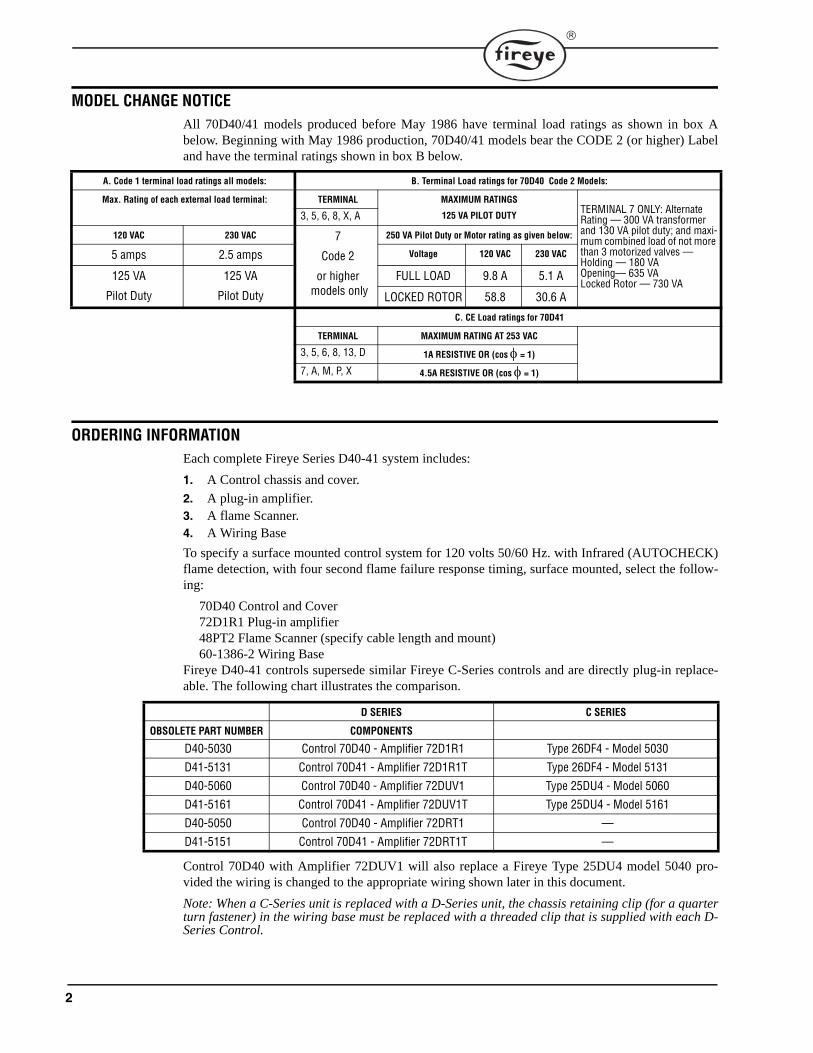
MODEL CHANGE NOTICEAll 70D40/41 models produced before May 1986 have terminal load ratings as shown in box Abelow. Beginning with May 1986 production, 70D40/41 models bear the CODE 2 (or higher) Labeland have the terminal ratings shown in box B below.
ORDERING INFORMATIONEach complete Fireye Series D40-41 system includes:
1. A Control chassis and cover.
2. A plug-in amplifier.3. A flame Scanner.4. A Wiring Base
To specify a surface mounted control system for 120 volts 50/60 Hz. with Infrared (AUTOCHECK)flame detection, with four second flame failure response timing, surface mounted, select the follow-ing:
70D40 Control and Cover72D1R1 Plug-in amplifier48PT2 Flame Scanner (specify cable length and mount)60-1386-2 Wiring Base
Fireye D40-41 controls supersede similar Fireye C-Series controls and are directly plug-in replace-able. The following chart illustrates the comparison.
Control 70D40 with Amplifier 72DUV1 will also replace a Fireye Type 25DU4 model 5040 pro-vided the wiring is changed to the appropriate wiring shown later in this document.
Note: When a C-Series unit is replaced with a D-Series unit, the chassis retaining clip (for a quarterturn fastener) in the wiring base must be replaced with a threaded clip that is supplied with each D-Series Control.
A. Code 1 terminal load ratings all models: B. Terminal Load ratings for 70D40 Code 2 Models:
Max. Rating of each external load terminal: TERMINAL MAXIMUM RATINGS
125 VA PILOT DUTYTERMINAL 7 ONLY: Alternate Rating — 300 VA transformer and 130 VA pilot duty; and maxi-mum combined load of not more than 3 motorized valves —Holding — 180 VAOpening— 635 VALocked Rotor — 730 VA
3, 5, 6, 8, X, A
120 VAC 230 VAC 7
Code 2
or higher models only
250 VA Pilot Duty or Motor rating as given below:
5 amps 2.5 amps Voltage 120 VAC 230 VAC
125 VA
Pilot Duty
125 VA
Pilot Duty
FULL LOAD 9.8 A 5.1 A
LOCKED ROTOR 58.8 30.6 A
C. CE Load ratings for 70D41
TERMINAL MAXIMUM RATING AT 253 VAC
3, 5, 6, 8, 13, D 1A RESISTIVE OR (cos = 1)
7, A, M, P, X 4.5A RESISTIVE OR (cos = 1)
D SERIES C SERIES
OBSOLETE PART NUMBER COMPONENTS
D40-5030 Control 70D40 - Amplifier 72D1R1 Type 26DF4 - Model 5030
D41-5131 Control 70D41 - Amplifier 72D1R1T Type 26DF4 - Model 5131
D40-5060 Control 70D40 - Amplifier 72DUV1 Type 25DU4 - Model 5060
D41-5161 Control 70D41 - Amplifier 72DUV1T Type 25DU4 - Model 5161
D40-5050 Control 70D40 - Amplifier 72DRT1 —
D41-5151 Control 70D41 - Amplifier 72DRT1T —

3
DESCRIPTION OF FIREYE SERIES D40-41 COMPONENTS
Control Chassis and Cover Amplifier Flame Scanner
Use with70D40 (120VAC) 50-60 Hzor70D41 (230VAC) 50/60 Hz
Rectification72DRT1 2-4 sec. FFRT72DRT1T 1 sec. FFRT
69ND1-1000K4 69ND1-1000K6 69ND1-1000K8
1/2" mount 12" (300mm) flame rod.1/2" mount 18" (450mm) flame rod.1/2" mount 24" (600mm) flame rod.
Infrared (IR) “Autocheck”72D1R1 2-4 sec. FFRT72D1R1T 1 sec. FFRT
*72D1R3 2-4 Sec. FFRT*72D1R3T 1 Sec. FFRT* For specific applications see note below.
48PT2-1003 48PT2-9003 48PT2-1007
48PT2-9007
1/2 straight mount 96" (2400mm) cable.1/2 angle mount 96" (2400mm) cable.1/2" straight mount 48" (1200mm) cable.1/2" angle mount 48" (1200mm) cable.
Ultraviolet (UV)72DUV1 2-4 sec. FFRT72DUV1T 1 sec. FFRT
UV8A UV1A3 UV1A6 UV2 UV90-3, -6, -9
45UV3-1050
1/2" angle mount 72" (1800mm) wire (no cable).1/2" straight mount 36" (900mm) cable.1/2" straight mount 72" (1800mm) cable.3/8" straight mount 36" (900mm) cable.90º side opening, 36" (900mm), 72" (1800mm),or 108" (2700mm) cable.3/4" straight mount cast aluminum housing,72" (1800mm) wire (no cable).
70D40 Only 72DUVS4 Repetitive Self-Check 2-4 sec. FFRT
72DUVS1T Repetitive Self-Check 1 sec. FFRT
45UV5-1009
or
45UV5-1008
1" NPT mount 72" (1800mm) wire (no cable), 120VAC shutter.or1" BSP mount 72" (1800mm) wire (no cable),120VAC shutter.
70D41 Only 72DUVS1T or 72DUVS4 45UV5-1007 1" BSP mount 72" (1800mm) wire, no cable. 230VAC shutter
Wiring Base 60-1386-2 Standard base for surface mounting60-1466-2 Open base for cabinet mounting
NOTE: Infrared “AUTOCHECK” amplifier modules 72D1R3, 72D1R3T, and 72D1R3T may be used for burner applications firing special fuel such as sawdust, sander dust, low BTU gas. The 72D1R3 type amplifiers are not to be used on any liquid fuel fired burner as it may result in malfunction causing damage to property and/or injury to personnel.
ACCESSORIES / SPARE PARTS
Part No. Description Used with Part No. Description Used with
4-263-1 Firetron Cell 48PT2 60-801 1/2" Coupling w/Pyrex Window 48PT2
4-314-1 UV Tube 45UV5, 45UV3 60-1199-1 1" NPT Coupling w/Quartz Window 45UV5-1009
10-88 Set of 3 orifice plugs 48PT2 60-1199-2 1" BSP Coupling w/Quartz Window 45UV5-1009
35-69 1/2" NPT Heat Insulator 48PT2-UV1 60-1257 1/2" Coupling w/Quartz Window UV1A
35-127-1 1" NPT Heat Insulator 45UV5-1009 60-1290 1/2" Coupling w/Quartz Lens UV1A
35-127-3 1" BSP Heat Insulator 45UV5-1007/8 60-1664-3 1" NPT Swivel Mounting Flange 45UV5-1009
46-38 Quartz Lens 45UV5 60-1664-4 1" BSP Swivel Mounting Flange 45UV5-1007/8
60-302 Swivel Mounting Flange 48PT2, UV1A 61-436 Lens Cap 48PT2

4
INSTALLATION
CAUTION: Installer must be a trained safety control technician. Verify that Electrical Power is disconnected before starting installation.
Follow the burner manufacturer’s instructions, if supplied. Otherwise proceed as follows.
Wiring Base
Mount the control wiring base on the burner or on a panel. The location should be free from exces-sive vibration and within the specified ambient temperature rating. The base may be mounted in anyangular position.
All wiring should comply with applicable electrical codes and be suitable for 75 C min. The terminalsin the wiring base are designed to permit a variety of connection methods - wire loop, eyelet, lug or quickconnect. A green grounding terminal is provided for equipment bonding. Circuit recommendations are pro-vided further on in this document. Consult with factory for assistance with non-standard applications.
APPROVALS70D41 only: TUV (Germany)70D40 only:Underwriters Laboratories Inc. Recognized: Guide MCCZ2, File MP 1537Factory Mutual System ApprovedNew York Board of Standards and Appeals 743-68-SA
ELECTRICAL RATINGSVA ratings (not specified as pilot duty) permit the connection of transformers and similar deviceswhose inrush current is approximately the same as their running current.
VA pilot duty ratings permit the connection of relays, solenoid valves, lamps, etc. whose total oper-ating load does not exceed the published rating and whose total inrush current does not exceed 10times the rating.
Running and locked rotor ratings are intended for motors. VA and VA (pilot duty) loads may beadded to a motor load provided the total load does not exceed the published rating.
Plug-in Module Retainer
Test Jack Black (-)
Cover Retainer
Plug-in Flame Amplifier
Test Jack Red (+)
APPROVALS 70D41ONLY TUV (GERMANY)
Chassis Retaining Screw
Load Relay
Test Points for Line and Load Voltages(70D40-150V AC Scale)(70D41-300V AC Scale)
Transformer

5
INSTALLING THE AMPLIFIER MODULETo assemble or disassemble a control and its plug-in amplifier module, place the unit on a workbench, remove the two module retainer hold down screws and lift off the module retainer. The mod-ule retainer cannot be removed if the control is secured onto a wiring base. Insert the appropriateamplifier module in the slots at the left side of the unit and gently push the module into position.
INSTALLING THE CONTROL
CAUTION: Be sure that the electrical power is shut off. When the wiring is completed and the plug-in module is installed, install the type D40, D41 unit on the wiring base.
Insert the slots at the bottom of the chassis in the tabs on the base. Push the chassis into position.Insert the screwdriver through the hole at the top of the chassis and tighten the chassis retainer screw.
INSTALLATION - UV SCANNERSCAUTION: The UV1A, UV2, UV8A, UV90 and 45UV3 ultra-violet flame scanners and asso-ciated amplifier modules are non-self-checking UV systems and should be applied only toburners that cycle often (e.g. a minimum of once per 12 hours) in order for the safety check-ing circuit to be exercised. (see Operation). If component checking is required during burneroperation for constantly fired burners, utilize the self-checking ultra-violet flame scanners(45UV5) and associated amplifier module (72DUVS4).
Where possible, obtain the burner manufacturer’s instructions for mounting the scanner. This infor-mation is available for most standard burners. The scanner mounting should comply with the follow-ing general instructions:
1. Position the UV1A, UV2, UV8A or UV90 scanner within 36 inches (900mm) of the flame to bemonitored; the 45UV5 within 72 inches (1800mm), closer if possible.
2. Select a scanner location that will remain within the ambient temperature limits of the UV Scan-ner (UV1A, UV2, UV8A, UV90, 45UV5; 200F, (93C). If cooling is required, use an insulat-ing coupling (Fireye #35-69 for UV1A, UV2 Scanners, #35-127-1 for 45UV5) to reduceconducted heat.
3. The UV1A, UV2, 45UV5 scanners are designed to seal off the sight pipe up to 1 PSI pressure.Higher furnace pressures should be sealed off. (To seal off positive furnace pressure up to 100PSI for UV1A, UV2 scanners, install a quartz window coupling (#60-1257) For 45UV5 scan-ners, use #60-1199 coupling. Add cooling air to reduce the scanner sight pipe temperature.
4. Install the scanner on a standard NPT pipe (UV1A, UV8A: 1/2 , UV2: 3/8, 45UV5: 1") whoseposition is rigidly fixed. If the scanner mounting pipe sights through the refractory, do not extend it
Replace the module retainer and tighten the two hold down screws. The unit cannot be installed on a wiring base if the module retainer is not in place.

6
more than halfway through. Swivel flanges are available (#60-302 for UV1A, UV2 scanners, #60-1664-3, -4 for 45UV5). The sight pipe must permit an unobstructed view of the pilot and/or mainflame, and both pilot and main flames must completely cover the scanner field of view.
Note: Since oil and gas flames radiate more ultraviolet energy from the base of the flame than fromfurther out in the flame this fact should be evaluated when installing the scanner sight pipe.
5. CAUTION: The scanner must not sight the ignition spark directly, or any part of theburner that can reflect the spark back to the scanner. The scanner must not see a pilotflame that is too small to reliably ignite the main flame.
6. Smoke or unburned combustion gases absorb ultraviolet energy. On installations with negativepressure combustion chambers, a small hole drilled in the UV1A, UV2 sight pipe will help tokeep the pipe clean and free from smoke. The 45UV5 has a 3/8 plug in the mounting flange thatcan be removed. For positive pressure furnaces, provide clean air to pressurize the sight pipe, if neces-sary.
7. Two UV1A, UV2, UV8A, UV90 or 45UV3 scanners may be installed on the burner if it is nec-essary to view two areas to obtain reliable detection of the flame. They should be wired in paral-lel. Only one repetitive self-checking 45UV5 scanner may be installed on a burner.
8. To increase scanner sensitivity with UV1A, UV2, UV8A scanners, a quartz lens permits locationof the scanner at twice the normal distance. Use 1/2 x 11/2 pipe nipple between UV1A Scannerand the coupling. Use 3/8 x closepipe nipple and a 1/2x
3/8bushing on UV2 installations.9. Request the assistance of any Fireye field office for recommendations of a proper scanner instal-
lation on a non-standard application.
Wiring — UV Scanners
To connect the scanner to the control, the UV1A Scanner is supplied with 36(900mm) or72mm) of flexible cable. The UV2 is supplied with 36" (900mm) of flexible cable.
45UV5 120 VAC and 230 VAC Models
CAUTION: Be sure to check that proper line voltage is matched to L1 and L2. Applying 230VAC to models 45UV5-1008 and 45UV5-1009 will damage scanner. 120 VAC applied to model45UV5-1007 will not operate scanner.
The 45UV5 is supplied with four 72" (1800mm) lead wires. Install them in a suitable length of flexi-ble armor cable and connect it to the control. A conduit connector is supplied with the scanner. Con-nect black wires (shutter) to terminals L1, L2; red wires (UV tube) to terminals S1, S2.
If it is necessary to extend the scanner wiring, the following instructions apply:
Scanner wires should be installed in a separate conduit. The wires from several scanners may beinstalled in a common conduit.
1. Selection of Wire
a. Use #14, 16 or 18 wire with 75C, 600 volt insulation for up to 100 (30.5M) foot distances(signal loss approximately 20% at 100 feet [30.5M]).
b. Extended Scanner Wiring: For extended scanner wiring up to 500 (152M) feet, and forshorter lengths to reduce signal loss, use a shielded wire (Belden 8254-RG-62/U coaxial cable,or equal) for each scanner wire of UV1A, UV2 and each red wire of the 45UV5. The endsof the shielding must be taped and not grounded.
c. Asbestos insulated wire should be avoided.
d. Multiconductor cable is not recommended without prior factory approval.
SCANNER MUST HAVE UNOBSTRUCTEDVIEW OF FLAME
NOT THIS NOT THIS BUT THIS
FLAME MUST COMPLETELY COVERSIGHT OPENING
NOT THIS NOT THIS BUT THIS

7
2. High voltage ignition wiring should not be installed in the same conduit with flame detector wires.
Typical Scanner Installations
INSTALLATION - INFRARED SCANNER TYPE 48PT2Where possible, obtain the burner manufacturer’s instructions for mounting the scanner, otherwiseproceed as follows:
A single scanner is used to detect both pilot and main flames. The sight pipe on which the scannermounts must be aimed so that the scanner sights a point at the intersection of main and pilot flames.
Proper scanner positioning must assure the following:
1. Reliable pilot flame signal.
2. Reliable main flame signal.3. A pilot flame too short or in the wrong position to ignite the main flame reliably, must not be
detected.4. Scanner must have an unobstructed view of flame being monitored.5. Flame being monitored must completely cover the scanner field of view.6. To avoid nuisance shutdowns, it is important to avoid sighting hot refractory and to keep scanner
temperature low (below 140 F, 60C).7. When the proper position has been established, drill a hole through the furnace wall and install a
4 to 8 length of threaded 1/2black iron pipe on which to mount the 48PT2 scanner.8. When satisfactory sighting position has been confirmed by operating tests, the sight tube should
be firmly welded in place.
SCANNER
The maximum UV signal from a flame is found in the first one-third of the visible flame taken from the point where the flame begins. The scanner sight pipe should be aimed at this area.
DO NOT EXTENDMORE THANHALF-WAY INTOREFRACTORY
FORCEDCLEAN AIR(FROM DISCHARGEOF FAN OR COMPRESSOR)
INSULATINGTUBING SEALING
UNION FORCEDAIR
EXTEND SIGHTING TUBE6”(1524) OR 8”(2032)
DO NOT EXTEND MORE THANHALF-WAY INTO REFRACTORY
METHODSOFCOOLINGSCANNER
CENTER LINEOF MAIN FLAME
SCANNERLINE-OF-SIGHT
SCANNER TARGETABOVE REFRACTORY
COMBUSTIONCHAMBER
PILOTBURNER
SCANNER
SCANNER
MAINBURNER
SCANNER MUST NOTSIGHT REFRACTORY
SCANNERLINE-OF-SIGHT

8
Wiring
Attach the cable supplied with the scanner to a junction box. Splice the cable wires to a pair of wiresnot smaller than #18. Install the complete run in a separate conduit to the control.
CAUTION: Continuous conduit bonding between scanner and the control is mandatory!Scanner may be located up to 100 feet (30.5M) from control. Do not pass scanner wiringthrough any junction box containing other wires. Do not run other wires through scannerconduit. Asbestos insulated wire should be avoided.
Keeping the Scanner Cool
The Infrared Scanner (Temperature Limit 140 F, 60 C) should never get too hot to grasp comfortably inthe hand. Keep the scanner cool by one or more of the following methods.
1. Use 6 to 8 (152mm - 203mm) length of pipe between scanner and hot furnace front plate.
2. Use insulating tube (Part No. 35-69) on the end of the iron pipe.3. Force air into sighting tube. Use Fireye Sealing Union (Part No. 60-801).4. Make sure sighting tube does not extend more than halfway into refractory wall.
INSTALLATION - 69ND1 FLAME RODThe 69ND1 flame rod proves a gas pilot flame and/or main gas flame. It is a spark plug type unit con-sisting of 1/2 NPT mount, a KANTHAL flame rod, a glazed porcelain insulating rod holder and a sparkplug connector for making electrical connections. The 69ND1 is available in 12mm 18 mmor 24 mm lengths.
The flame rod may be located to monitor only the gas pilot flame or both the gas pilot and main gasflames. It is mounted on a 1/2NPT coupling.
The following instructions should be observed:
1. Keep flame rod as short as possible.
2. Keep flame rod at least 1/2from any refractory.3. Flame rod should enter the pilot flame from the side so as to safely prove an adequate pilot flame
under all draft conditions.4. If the flame is nonluminous (air and gas mixed before burning), the electrode tip should extend
at least 1/2.7mm) into the flame, but not more than half-way through.
5. If the flame is partly luminous, the electrode tip should extend only to the edge of the flame. It isnot necessary to maintain absolutely uninterrupted contact with the flame.
6. It is preferable to angle the rod downward to minimize the effect of sagging and to prevent itfrom coming in contact with any object.
7. An adequate grounding surface for the flame must be provided. The grounding surface in actualcontact with the flame must be at least four times greater than the area of the portion of the flamerod in contact with the flame. It is essential to adjust the flame rod and ground area ratio to pro-vide a maximum signal reading.
WRONG POSITIONOF ROD
INADEQUATE FLAME
PILOT BURNER
CORRECT POSITIONOF PILOT FLAME
CORRECTPOSITIONOF ROD

9
Note: Interference from the ignition spark can alter the true signal reading by adding to, or subtracting fromit. This trend sometimes may be reversed by interchanging the primary wires (line voltage) to the ignitiontransformer and may be made ineffective by the addition of grounded shielding between the flame rod andignition spark. This interference can also be reduced by the addition of grounded shielding between the flamerod and ignition spark.8. Proven types of flame grounding adapters, as shown below, may be used to provide adequate
grounding surface. High temperature stainless steel should be used to minimize the effect ofmetal oxidation. This assembly may be welded directly over the pilot or main burner nozzle.
TYPICAL WIRING ARRANGEMENTSFireye D40-41 controls may be used on a variety of types of fuel burners and provide a variety offunctions. The typical schematic diagrams shown on the following pages illustrate a simple, and amore complex method of applying the controls to conventional burner installations. (They are forinformation only, and not intended to represent a complete system. Applicable safety codes mayrequire additional circuits and interlocks.) Additionally, they may be used as flame switches, cas-caded on multiple burner installations, in redundant arrangements, etc. Contact any Fireye SalesOffice for assistance in designing burner control circuits with additional functions.
FIGURE 1. SCHEMATIC DIAGRAM OF TYPE D40, D41 CONTROLS
BOMB FINGROUNDING ASSEMBLY
THREADED ROD ASSEMBLY
10 11 L1 L2 3 M D P X
RL RELAY
PLUG-INFLAMESIGNAL AMPLIFIER
RF RELAY
H
POWERINPUT
N
12 13 5 6 7 8 A S1 S2
FLAMESCANNER
BONDINGCONNECTION(GROUND)
S2S1L1 L2RED
BLACK
* SCANNERTYPE 45UV5-1007 (D41) (230VAC) 50/60 HZTYPE 45UV5-1008 (D40) (120VAC) 50/60 HZTYPE 45UV5-1009 (D40) (120VAC) 50/60 HZ
TESTJACKS
RL-2
RF-2 RL-3
RF-3 RF-4
RF-1
TO FLAMESIGNALAMPLIFIER
RL-1
INTERNAL WIRING DIAGRAM
*
INTERNAL
EXTERNAL

10
FIGURE 2. TYPICAL SCHEMATIC DIAGRAM FOR SEMI-AUTOMATIC PILOT IGNITED GAS BURNER WITH PROVED INTERMITTENT PILOT
FIGURE 3. TYPICAL SCHEMATIC DIAGRAM FOR SEMI-AUTOMATIC PILOT IGNITED GAS OR OIL BURNER WITH PREPURGE, PILOT TFI, MAIN FLAME TFI AND INTERRUPTED PILOT
NOTE: When a flame rod is used, jumper S2 to the terminal board screw directly above S2 terminal on mount-ing base.
The self-checking circuitry in the 72DUVSIT and 72DUVS4 amplifiers is designed to be used with only one45UV5 type scanner connected. When two 45UV5 scanners are used, wire the two black L1 and L2 leads in par-allel and switch the two red S1 and S2 leads with a relay or selector switch.
CAUTION: Only one scanner can be in the S1 and S2 circuit at one time.
10 11 L1 D P X
RL RELAY
PLUG-INFLAMESIGNAL AMPLIFIER
RF RELAY
H
N
12 13 5 A
FLAMESCANNER
BONDINGCONNECTION(GROUND)
TEST JACKS
* SCANNERTYPE 45UV5-1007 (D41) (230VAC) 50/60 HZTYPE 45UV5-1008 (D40) (120VAC) 50/60 HZTYPE 45UV5-1009 (D40) (120VAC) 50/60 HZ
BURNER SWITCH
DISCONNECTMEANS AND OVERLOADPROTECTIONREQUIRED
TO FLAMESIGNALAMPLIFIER
7
FLAMEON
PILOTVALVE
ALARM
MAINFUELVALVE
RL-2
RF-1
RL-1
RF-4RF-3
RL-3RF-2
IGNITION TRANSFORMER
ALLLIMITS
RUNNINGINTERLOCKS
SUPPLY
L2
MOMENTARYCONTACTSTART SWITCH
S2S1L1 L2RED
BLACK
S1 S2
*
INTERNAL
EXTERNALM3 86
10 11 L1 M P X
RL RELAY
PLUG-INFLAMESIGNAL AMPLIFIER
RF RELAY
H
N
12 13 8 A S1 S2
FLAMESCANNER
BONDINGCONNECTION(GROUND)
*SCANNERTYPE 45UV5-1007 (D41) (230VAC) 50/60 HZTYPE 45UV5-1008 (D40) (120VAC) 50/60 HZTYPE 45UV5-1009 (D40) (120VAC) 50/60 HZ
BURNER SWITCH
DISCONNECTMEANS AND OVERLOADPROTECTIONREQUIRED
TO FLAMESIGNALAMPLIFIER
7
ALARM
MAINFUELVALVE
RL-2
RF-1
RL-1
RF-4RF-3
RL-3RF-2
IGNITION TRANS-
ALLLIMITS
RUNNINGINTERLOCKS
SUPPLY
L2
MOMENTARYCONTACTSTART SWITCH
STARTINGINTERLOCKS
FORMER
TB TC
TB-1I.C.T.O.
TA
TC-1(TO)
TA-2(TO)
PURG-ING
FLAME
OFF ON
ALARMSILENCING SWITCH
S2S1L1 L2RED
BLACK
TA - Purge Timer, D.P.S.T. contact, delay after energize (D.A.E.) adjustable for required air changes.TC - Pilot trial-for-ignition timer S.P.S.T. contacts, delay after energize (D.A.E.) set for 10 seconds maximum.TB - Main flame trial-for-ignition timer. Two sets N.O. contacts. I.C. time open. delay after de-energize (D.A.D.E.).
IC - Instant closed.TO - Timed open.TC - Timed closed
TA-1(TC)
INTERNAL
EXTERNAL
*
TB-2I.C -T.O.
PILOTVALVE
5 63 D
TEST JACKS

11
DESCRIPTION OF OPERATION OF TYPICAL SINGLE BURNER SYSTEM (refer to Figure 3)NOTE: With 72D1R1 Amplifier, Terminals L1 and L2 must be powered for 15 seconds before theflame signal amplifier will operate.1. With power applied, burner switch closed, limit switches closed, air flow and fuel interlock
closed, the “Flame Off” light, the purge timer TA and “Purging” light are energized. The “AlarmSilencing” switch should be switched to the “Silent” position.
2. When the prepurge period expires, contacts TA2 open and de-energize the “Purging” light. Con-tacts TA1 close. The operator depresses and holds the momentary contact “Start” switch.
3. The circuit to Terminals P-3-11 is completed through the starting interlocks and contacts TA,and the RL relay is energized. Terminal 7 is energized. The “Alarm Silencing” switch should beswitched to the “Alarm” position.
4. The ignition transformer, timers TB and TC, and the pilot gas valve are energized. Pilot flame isestablished and detected. Relay RF is energized.
5. The operator releases the “Start” switch. The ignition transformer and timers TB and TC are de-energized. The main fuel valve is energized.
6. When the main flame trial for ignition expires, contacts TB1 open and de-energize the pilotvalve, TB2 open and reset the purge timer.
7. The burner will continue to fire until power is shut off, or the limit and operating control circuitopens, or a flame failure occurs.
INSTALLATION TESTINGTesting Fireye D40-41 controls is accomplished with the use of an AC-DC test meter with 1,000ohm/volt input impedance, or a digital meter with 500K input impedance or greater. Test points arelocated on the chassis board to assist with measuring line and load voltages. For this test the metershould be set on the 150 volt AC scale (D40), 300 volt AC scale (D41). Test jacks are located on theamplifier for measuring flame signal strength. For this test the meter should be set on a scale to reada normal 20-25 volts DC. The DC test voltage may vary plus or minus 5 volts, but should not fluctu-ate with an acceptable flame signal.
Note: The Fireye 45UV5 is a repetitive self-check scanner that contains a highly reliable shutter thatcloses every 4 seconds to initiate a system check. When the shutter closes, the test jack voltageshould go down to approximately zero, and then back to the normal reading.
Normal Pilot Test1. Manually shut off the main fuel supply.
2. Initiate a normal start.3. When the pilot flame is present, observe the test meter. If the meter reading is low, or fluctuates,
increase the size of the pilot flame, improve the alignment of the sight pipe, move the flamescanner closer to the pilot flame, or verify that the flame scanner is clean.
Minimum Pilot Test
This test insures that the flame scanner will not detect a pilot flame too small to reliably light themain flame. It should be made by a qualified person on every new installation and following anyrepositioning of the flame scanner.
1. Manually shut off the main fuel supply.
2. Initiate a normal start up.3. When the pilot flame is detected, observe the test meter and reduce the size of the pilot flame
until the flame relay just remains energized.4. Manually, slowly turn on the main fuel which must light immediately from the reduced pilot
flame.
CAUTION: If main flame light off is delayed, shut off the fuel immediately. Realign the flamescanner so that pilot flame detection requires a larger pilot flame. Repeat this test until themain flame lights reliably with a minimum pilot flame.
5. After the minimum pilot test is completed satisfactorily, increase the pilot flame to normal size.

12
This test should be made on every new installation and following change-out of the controland/or flame detector, any repositioning of the flame detector, air/fuel ratio adjustment orany other changes that may interfere with reliable light-off of the main fuel.
Test for Spark Pickup (Only required on UV Controls)1. Shut off all fuel.
2. Initiate a start-up with only the spark ignition energized.3. Observe the test meter. It should read no more than one volt. If a test meter reading reveals that
UV from the spark is being detected, realign the sight pipe to eliminate it. Relocate the spark orinstall a shield to obscure the spark signal from the flame scanner.
4. If a flame scanner sighting change has been made, recheck for normal pilot flame detection.
EXTERNAL METER CONNECTIONS
The test jacks are located on the amplifier card, if external access is desired for a panel meter theshown below will assist you in locating the position to drill through on the front cover. The hole sizesshould be large enough to accommodate the body of the meter probes. The test jacks accept meterprobes up to .080” or 2mm diameter.
MAINFLAME
REFRACTORY
MAINBURNER
PILOTFLAME
SCANNERPILOT
BURNER
INSUFFICIENT PILOT
MAINFLAME
REFRACTORY
MAINBURNER
PILOTFLAME
SCANNERPILOT
BURNER
MINIMUM PILOT
MAINFLAME
REFRACTORY
MAINBURNER
PILOTFLAME
SCANNERPILOT
BURNER
NORMAL PILOT
RECOMMED5/16” TO 3/8” HOLES
TO ACCOMODATE METER PROBES
1.625
4.73125
.625
ADDING HOLES IN COVER TO ACCESS TEST JACKS
+
+
13
MAINTENANCE
Humidity Effects
It is good practice to minimize any possible adverse effects of high humidity by keeping controlequipment continuously powered, even during periods when it is not in use.
Scanner
The viewing window must be kept clean. Even a small amount of contamination will reduce theflame signal reaching the flame scanner. A routine schedule should be set up. Wipe the scanner witha clean soft cloth. If necessary, dampen the cloth with concentrated detergent.
Type 48PT2 scanners include a replaceable #4-263-1 Firetron cell.
Type 45UV5 and 45UV3 scanners include a replaceable #4-314-1 UV tube.
RECOMMENDATION — Periodic Safety Checks
It is recommended that a procedure be established to test at least once a month, the complete flamesafeguard system. The test should verify flame failure safety shutdown, limit switch and interlockfunction and positive fuel cutoff when the valves are de-energized.
Rotation
It is recommended that control and scanner units purchased as spares be installed periodically.
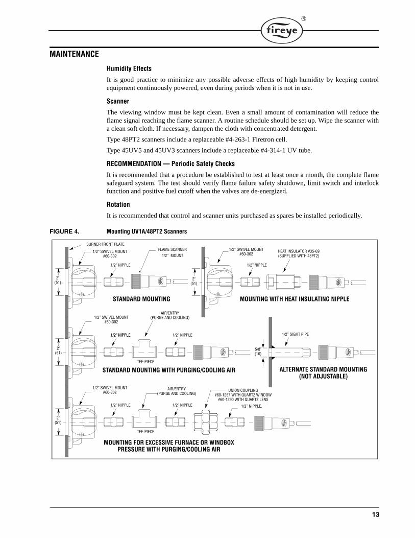
FIGURE 4. Mounting UV1A/48PT2 Scanners
AIR/ENTRY(PURGE AND COOLING)
UNION COUPLING#60-1257 WITH QUARTZ WINDOW
#60-1290 WITH QUARTZ LENS
1/2” NIPPLE
HEAT INSULATOR #35-69(SUPPLIED WITH 48PT2)
1/2” SWIVEL MOUNT#60-302
MOUNTING WITH HEAT INSULATING NIPPLE
1/2” NIPPLE
1/2” SWIVEL MOUNT#60-302
STANDARD MOUNTING
BURNER FRONT PLATEFLAME SCANNER
1/2” MOUNT
1/2” NIPPLE
1/2” SWIVEL MOUNT#60-302
STANDARD MOUNTING WITH PURGING/COOLING AIR
1/2” NIPPLE 1/2” NIPPLE
TEE-PIECE
1/2” NIPPLE
1/2” SWIVEL MOUNT#60-302
MOUNTING FOR EXCESSIVE FURNACE OR WINDBOXPRESSURE WITH PURGING/COOLING AIR
1/2” NIPPLE
TEE-PIECE
1/2” NIPPLE,
AIR/ENTRY(PURGE AND COOLING)
1/2” SIGHT PIPE
ALTERNATE STANDARD MOUNTING(NOT ADJUSTABLE)
5/8"(16)
2"(51)
2"(51)
2"(51)
2"(51)

14
FIGURE 5. WIRING BASE TERMINAL LAYOUT
RIGHT SIDELEFT SIDE
BONDING
CONNECTION
S2
S1
A
8
7
6
5
13
12
X
P
D
M
3
L2
L1
11
10

15
Component Dimensions
6(152)
5 3/4(146)
CONTROL WITH COVERAND WIRING BASE
WIRING BASEMOUNTING HOLES
7 9/32(185)
KNOCKOUTS FOR1/2" CONDUIT (7)
4 7/8(123.8)
5 11/16(144.5)
2 7/16(61.9)
5 1/4(133)
7(177.8)
11/16(17.4)
1 3/4(44.4) 25/32
(19.8)
1/4TYP
(6.35)25/64TYP(9.9)
KNOCKOUTS FOR1/2” CONDUIT (7)
1 1/16(27)
1 3/16(30.2)
13/64(5.1)
HOLE FOR3/4”
SIGHTINGPIPE
SCREW,1/4-20 THD
2” (51) CLEARANCE REQUIRED TO REMOVE
2”(51)
1/2-1STRAIGHT PIPE THD
8 1/4”(210)
45O
3/8-18 NPT FORPURGE AIR CONNECTION
4” (102)1 11/16”
HEX(43)
1-11 1/2 NPTFOR SIGHT
TUBE
36” (1m APPROX.)TC-ER CABLE
3/8” PIPE THREAD
1.06” DIA.(27.0)
UV2 UV SCANNER
UV SELF-CHECKSCANNER
TYPE 45UV5MODEL 1009
2.53”(64.3)
1/2-14 STRAIGHTFEMALE PIPE THREAD
1.06” DIA(27.0)
UV1A UV SCANNER
36” TC-ER CABLE (UV-1A-3)72” TC-ER CABLE (UV-1A-6)
72” LEAD
2 7/8”(73)
2”(50.8)
1 5/8”(41)
3 1/4”(82)
UV SCANNERType: 45UV3Model: 1050
2 3/8”(60.3)
2 3/8”(60.3)
1/2”(12.7)
”L”
1/2”-14 NPT
13/16” HEX(20.6)
15/16” HEX(23.8)
”L” LENGTH AS SPECIFIED: 12”, 18”, 24” (304.8, 457.2, 609.6)
69ND1 FLAME ROD
2.504”(63.6)
2 1/2”(63.5)
WHEN ASSEMBLED
1 1/4” DIA.(31.8)
1.063” DIA.
HEAT INSULATOR.345” (8.7)TC-ER CABLE
1/2-14TAPEREDPIPE THD
1/2-14STRAIGHT PIPE THD
48PT2-1000 SERIES INFRARED SCANNER
2 1/2”(63.5)
WHEN ASSEMBLED
1 1/4” DIA.
1.02”DIA(26.0)
HEAT INSULATOR1/2-14
TAPEREDPIPE THD
2.13”(54.0)
1.46”(37.1) 13/32” (10)
48PT2-9000 SERIES INFRARED SCANNER
All di i i i h ( illi i h )
0.880"(22.3MM)
1.90(48.2MM)
1.406"(35.7MM)
1.48"(37.6MM)
0.875"(37.6MM)
3.75"(95.7MM)
0.5"(12.7MM)
UV90 MOUNTING BLOCK(Included with Scanner)
UV90 SCANNER
.345” DIA. (8.7) TC-ER CABLE
3.96”:(100.6)
2.58”(50.8)

16
NOTICEWhen Fireye products are combined with equipment manufactured by others and/or integrated intosystems designed or manufactured by others, the Fireye warranty, as stated in its General Terms andConditions of Sale, pertains only to the Fireye products and not to any other equipment or to thecombined system or its overall performance.
WARRANTIESFIREYE guarantees for one year from the date of installation or 18 months from date of manufactureof its products to replace, or, at its option, to repair any product or part thereof (except lamps andphotocells) which is found defective in material or workmanship or which otherwise fails to conformto the description of the product on the face of its sales order. THE FOREGOING IS IN LIEU OFALL OTHER WARRANTIES AND FIREYE MAKES NO WARRANTY OF MERCHANT-ABILITY OR ANY OTHER WARRANTY, EXPRESS OR IMPLIED. Except as specificallystated in these general terms and conditions of sale, remedies with respect to any product or partnumber manufactured or sold by Fireye shall be limited exclusively to the right to replacement orrepair as above provided. In no event shall Fireye be liable for consequential or special damages ofany nature that may arise in connection with such product or part.
FIREYE D-40413 Manchester Road JULY 8, 2013Derry, New Hampshire 03038 USA Supersedes April 4, 2013www.fireye.com


