Control Systems for Multi-rotorsPrinciples, Modeling and Software Design
Corrado Santoro
ARSLAB - Autonomous and Robotic Systems LaboratoryDipartimento di Matematica e Informatica - Universita di Catania, Italy
Corrado Santoro Control Systems for Multi-rotors
Multirotor Structure and Dynamics
Multirotor Structure and Dynamics
Corrado Santoro Control Systems for Multi-rotors
Multirotors: definition
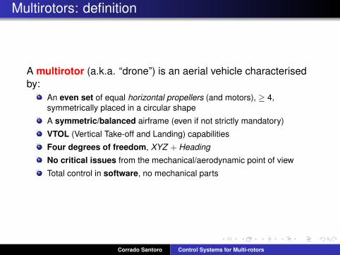
A multirotor (a.k.a. “drone”) is an aerial vehicle characterisedby:
An even set of equal horizontal propellers (and motors), ≥ 4,symmetrically placed in a circular shape
A symmetric/balanced airframe (even if not strictly mandatory)
VTOL (Vertical Take-off and Landing) capabilities
Four degrees of freedom, XYZ + Heading
No critical issues from the mechanical/aerodynamic point of view
Total control in software, no mechanical parts
Corrado Santoro Control Systems for Multi-rotors

Reference System
The body reference system usually employed is the one in figure
The system also define the Euler angles that represents the attitude:roll, φpitch, θyaw, ψ
The pose of the multirotor is represented by:{X ,Y ,Z , φ, θ, ψ}, in the Earth frame
Corrado Santoro Control Systems for Multi-rotors

Airframes and Constraints
Motors/propellers must be the sameMotors/propellers must be even ≥ 4Motors/propellers must be placed in a circular shapePropellers must rotate in opposite directions in-pair (third Newton’sLaw compensation)Propellers must have opposite pitches in-pairThe number and position of propellers define the airframe model
Corrado Santoro Control Systems for Multi-rotors
Motion
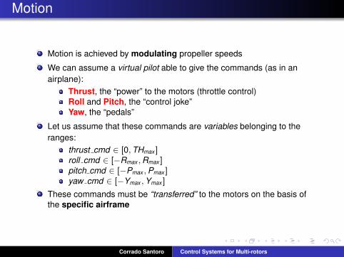
Motion is achieved by modulating propeller speeds
We can assume a virtual pilot able to give the commands (as in anairplane):
Thrust, the “power” to the motors (throttle control)Roll and Pitch, the “control joke”Yaw, the “pedals”
Let us assume that these commands are variables belonging to theranges:
thrust cmd ∈ [0,THmax ]roll cmd ∈ [−Rmax ,Rmax ]pitch cmd ∈ [−Pmax ,Pmax ]yaw cmd ∈ [−Ymax ,Ymax ]
These commands must be “transferred” to the motors on the basis ofthe specific airframe
Corrado Santoro Control Systems for Multi-rotors

Motion: Hovering and Z-translation
Vertical motion is achieved by keeping all propeller speeds the same andproportional to a thrust command (we assume 1-proportionality):
ω1 = thrust cmd
ω2 = thrust cmd
ω3 = thrust cmd
ω4 = thrust cmd
Corrado Santoro Control Systems for Multi-rotors
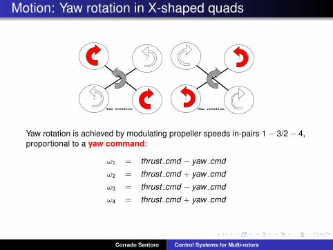
Motion: Yaw rotation in X-shaped quads
Yaw rotation is achieved by modulating propeller speeds in-pairs 1− 3/2− 4,proportional to a yaw command:
ω1 = thrust cmd − yaw cmd
ω2 = thrust cmd + yaw cmd
ω3 = thrust cmd − yaw cmd
ω4 = thrust cmd + yaw cmd
Corrado Santoro Control Systems for Multi-rotors

Motion: Roll rotation in X-shaped quads
Roll rotation is achieved by modulating propeller speeds in-pairs 1− 4/2− 3,proportional to a roll command:
ω1 = thrust cmd − yaw cmd + roll cmd
ω2 = thrust cmd + yaw cmd − roll cmd
ω3 = thrust cmd − yaw cmd − roll cmd
ω4 = thrust cmd + yaw cmd + roll cmd
Roll rotation implies a decomposition of the thrust force: a drag forceappears that drives the frame in a translated flight along Y axis
Corrado Santoro Control Systems for Multi-rotors
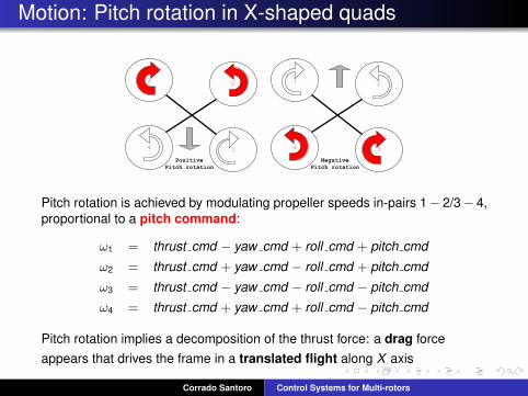
Motion: Pitch rotation in X-shaped quads
Pitch rotation is achieved by modulating propeller speeds in-pairs 1− 2/3− 4,proportional to a pitch command:
ω1 = thrust cmd − yaw cmd + roll cmd + pitch cmd
ω2 = thrust cmd + yaw cmd − roll cmd + pitch cmd
ω3 = thrust cmd − yaw cmd − roll cmd − pitch cmd
ω4 = thrust cmd + yaw cmd + roll cmd − pitch cmd
Pitch rotation implies a decomposition of the thrust force: a drag forceappears that drives the frame in a translated flight along X axis
Corrado Santoro Control Systems for Multi-rotors

Motion in Plus-shaped quads
ω1 = thrust cmd − yaw cmd + pitch cmdω2 = thrust cmd + yaw cmd − roll cmdω3 = thrust cmd − yaw cmd − pitch cmdω4 = thrust cmd + yaw cmd + roll cmd
Corrado Santoro Control Systems for Multi-rotors

Motion: the Mixer
The mixer is the software component that translates attitudecommands to motor commandsIt depends airframe model and basically implements a matrix M suchthat ω1
ω2
· · ·ωn
= M
roll cmdpitch cmdyaw cmd
thrust cmd
Corrado Santoro Control Systems for Multi-rotors

The Mixer: practical aspects
Practically, the outputs of the mixer are not the wn but the duty cyclevalues of the motor PWM drivers PWM1
PWM2
· · ·PWMn
= M
roll cmdpitch cmdyaw cmd
thrust cmd
PWM values are then saturated using a technique that avoids certainside-effects
Corrado Santoro Control Systems for Multi-rotors

The Control System
The Control System of a Multirotor
Corrado Santoro Control Systems for Multi-rotors

Rate and Attitude Control
The mixer outputs PWM values and does not have control on the realforces of the propellers
In order to ensure stability, proper sensors must be employed thatdetects the attitude of the multirotor
The control of stability is achieved by means of two control loops:Rate Control, controls angular speeds φ, θ, ψ, by means of a3-axis gyroAttitude Control, controls Euler angles φ, θ, ψ, by means of a6-DOF or 9-DOF IMU
Corrado Santoro Control Systems for Multi-rotors

Rate Control: the “Acro” Mode
The Rate Control module performs a PID control on angular ratesφ, θ, ψ on the basis of:
Target Rates, given as inputCurrent Rates, given by the gyro
When the target rates are given by the RC command, the mode iscalled acrobatic
Corrado Santoro Control Systems for Multi-rotors
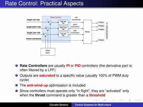
Rate Control: Practical Aspects
Rate Controllers are usually PI or PID controllers (the derivative part isoften filtered by a LPF)
Outputs are saturated to a specific value (usually 100% of PWM dutycycle)
The anti-wind-up optimisation is included
Since controllers must operate only “in flight”, they are “activated” onlywhen the thrust command is greater than a threshold
Corrado Santoro Control Systems for Multi-rotors

Rate Control: Implementation
Rate Control module is implemented as a periodic task triggered by:A Timer, with a specific periodThe gyro sampling frequency
Periods are in the order of 200− 500Hz
The code implements the classical PID algorithm with anti-wind-up
Corrado Santoro Control Systems for Multi-rotors

Rate Control: Implementation
Pseudo-code
while True doOn each ∆T ;{φT , θT , ψT , thrust cmd} ← read remote control();{φ, θ, ψ} ← read gyro();// Control
roll cmd ← PID roll rate controller(φT − φ);pitch cmd ← PID pitch rate controller(θT − θ);yaw cmd ← PID yaw rate controller(ψT − ψ);// MixerPWM1 ← thrust cmd − yaw cmd + roll cmd + pitch cmd ;PWM2 ← thrust cmd + yaw cmd − roll cmd + pitch cmd ;PWM3 ← thrust cmd − yaw cmd − roll cmd − pitch cmd ;PWM4 ← thrust cmd + yaw cmd + roll cmd − pitch cmd ;// Drivingdrive motor(PWM1,PWM2,PWM3,PWM4);
end
Corrado Santoro Control Systems for Multi-rotors
Rate and Attitude Control
Rate control ensures that real angular rates are the one desired but donot provide guarantees on the attitude, i.e. that the pose of the airframeis a specific one {φ, θ, ψ}
Moreover, starting from an horizontal pose φ = 0, θ = 0, if a “glitch”moves suddenly the pitch angle to θ = 10◦, the system is stable fromthe rate control point of view (there are no rotations), but (probably) theattitude is not the desired one
An Attitude Controller is required, which drives the Rate Controllersand ensures the respect of a certain pose, from the Euler angles pointof view
To this aim, the current attitude is estimated by integrating data fromgyros, accelerometers and magnetometers.
Corrado Santoro Control Systems for Multi-rotors

Attitude Control: Basic Schema
Attitude Controllers are (usually) simple P controllersOutputs are saturated to a maximum angular speed, determinedexperimentallyAttitude Control module is implemented as a periodic task (like theRate Control), with a period same as to (or greater than) that of RateControl
Corrado Santoro Control Systems for Multi-rotors
Attitude/Rate Control: Implementation
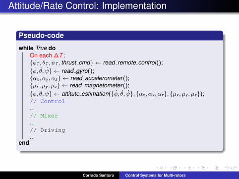
Pseudo-code
while True doOn each ∆T ;{φT , θT , ψT , thrust cmd} ← read remote control();{φ, θ, ψ} ← read gyro();{αx , αy , αz} ← read accelerometer();{µx , µy , µz} ← read magnetometer();{φ, θ, ψ} ← attitute estimation({φ, θ, ψ}, {αx , αy , αz}, {µx , µy , µz});// Control...// Mixer...// Driving...
end
Corrado Santoro Control Systems for Multi-rotors

Attitude/Rate Control: Implementation
Pseudo-code
while True doOn each ∆T ;...{φ, θ, ψ} ← attitute estimation({φ, θ, ψ}, {αx , αy , αz}, {µx , µy , µz});// Control
φT ← PD roll controller(φT − φ);θT ← PD pitch controller(θT − θ);ψT ← PD yaw controller(ψT − ψ);
roll cmd ← PID roll rate controller(φT − φ);pitch cmd ← PID pitch rate controller(θT − θ);yaw cmd ← PID yaw rate controller(ψT − ψ);// Mixer...// Driving...
end
Corrado Santoro Control Systems for Multi-rotors
Attitude/Rate Control: Implementation
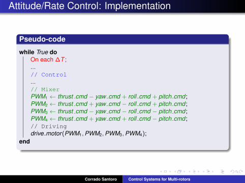
Pseudo-code
while True doOn each ∆T ;...// Control...// MixerPWM1 ← thrust cmd − yaw cmd + roll cmd + pitch cmd ;PWM2 ← thrust cmd + yaw cmd − roll cmd + pitch cmd ;PWM3 ← thrust cmd − yaw cmd − roll cmd − pitch cmd ;PWM4 ← thrust cmd + yaw cmd + roll cmd − pitch cmd ;// Drivingdrive motor(PWM1,PWM2,PWM3,PWM4);
end
Corrado Santoro Control Systems for Multi-rotors
Attitude Estimation
Attitude Estimation
Corrado Santoro Control Systems for Multi-rotors

Attitude Estimator
The most critical part of Attitude Control is the Sensor Fusionalgorithm that implements the Attitude Estimator
The literature reports a plethora of solutions:Kalman FiltersComplementary FiltersDirection Cosine Matrix AlgorithmGradient Descend...
(Some) quality factors of the estimator:Resilience to vibrationsDifference w.r.t. the real attitudeRate of convergence
Corrado Santoro Control Systems for Multi-rotors

Attitude Estimator: Basics
The basic working scheme of the estimator is the following:
1 Wait sampling period2 Update Euler angles using data from gyroscopes by performing
discrete integration3 Adjust Pitch and Roll on the basis of data from accelerometers (−→g
vector)4 Adjust Yaw on the basis of data from magnetometers (
−→N vector)
The various algorithms differ in the way in whichadjustments (steps 2 and 3) are performed
Corrado Santoro Control Systems for Multi-rotors
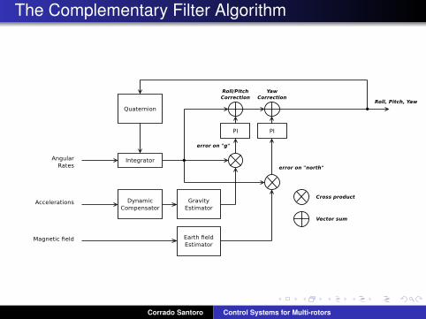
The Complementary Filter Algorithm
Corrado Santoro Control Systems for Multi-rotors

The Direction Cosine Matrix Algorithm
The DCM is the rotation matrix from “Earth reference” and “Bodyreference” of a rigid body whose attitude is expressed by means ofEuler angles θ, φ, ψ
Direction Cosine Matrix
DCM =
cθcψ sφsθcψ − cφsψ cφsθcψ + sφsψcθsψ sφsθsψ + cφcψ cφsθsψ − sφcψ−sθ sφcθ cφcθ
s = sin, c = cos
A vector v ′ = (x ′, y ′, z′) in local (body) frame is translated into global(Earth) frame by multiplying it by the DCM: v = DCM · v ′
Corrado Santoro Control Systems for Multi-rotors

Direction Cosine Matrix
The DCM has some properties
It is orthogonal, its transpose is equal to its inverse:
DCM−1 = DCMT
DCM · DCMT = I
Orthogonality implies that the columns (rows)are orthogonal vectors in-pair→ their cross product is zeroare vector with module equal to 1
Such properties must be always respected
Corrado Santoro Control Systems for Multi-rotors

The DCM Algorithm
Corrado Santoro Control Systems for Multi-rotors

Attitude Estimators: Improving the Quality
Sensor CalibrationGyros: get (and store) offsets bw and remove them frommeasures: ω = ω − bw
Accelerometers: get (and store) offsets ba and rotation matrixRA remove them from measures: a = RA · (a− ba)Magnetometers: get (and store) offsets bm and rotation matrixRM remove them from measures: m = RM · (m − bm)
Sensor Filtering, low-pass filters (with order ≥ 2) are often used toreduce the effect of motor/propeller vibrations
Mechanical Dampers, to decouple the flight control board from theairframe to reduce the effect of motor/propeller vibrations
Dynamic g compensation, the contribution of accelerometers isweighted according to the error |g − ‖a‖| in order to reduce the effect,on a, of body translations
Corrado Santoro Control Systems for Multi-rotors
Summary of Basic Software Modules
Summary of basic Software Modules
Corrado Santoro Control Systems for Multi-rotors

In Summary... the Basic Software Modules
Corrado Santoro Control Systems for Multi-rotors

Other Kind of Controls
Other Kind of Controls
Corrado Santoro Control Systems for Multi-rotors

Altitude Control
Altitude ControlAltitude Z is estimated by means of proper sensors (barometer, insome case integrated with measures from accelerometers, ultrasonicsensors, etc.)
The Vertical Speed Vz is determined by a derivative of the altitude
Control is performed by means of two control loops that drive the thrustcommand
An inner PI(D) speed controller driving the thurstAn outer P-(FF) position controller driving the speed controller
Corrado Santoro Control Systems for Multi-rotors
Position Control
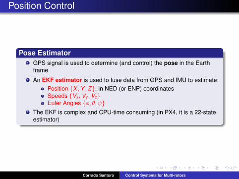
Pose EstimatorGPS signal is used to determine (and control) the pose in the Earthframe
An EKF estimator is used to fuse data from GPS and IMU to estimate:Position {X ,Y ,Z}, in NED (or ENP) coordinatesSpeeds {Vx ,Vy ,Vz}Euler Angles {φ, θ, ψ}
The EKF is complex and CPU-time consuming (in PX4, it is a 22-stateestimator)
Corrado Santoro Control Systems for Multi-rotors

Position Control
Position ControlPosition Control is performed by means of two pair of control loops(North and East) that drive the target roll and pitch of the attitudecontroller
An inner PI(D) speed controller driving the target attitude (roll andpitch)An outer P-(FF) position controller driving the speed controller
Corrado Santoro Control Systems for Multi-rotors
The Ground Control Station
Ground Control Station
Corrado Santoro Control Systems for Multi-rotors

The Ground Control Station
GCSMost of the UAV flight stacks have the possibility of connecting a setup,telemetry and maintenance GUI called Ground Control Station
It can be used forConfiguring the UAV and calibrating the sensorMonitoring telemetry dataPlanning the missionsModifying all the parameters (gains of controllers or of the sensorfusion algorithms, sensor configuration, RC commands, etc.)
Corrado Santoro Control Systems for Multi-rotors

The Ground Control Station
MAVLinkCommunication between GCS and the Flight Stack is performedthrough a standard protocol called MAVLinkIt is designed to be used in serial links (wired or radio) or TCP/UDPchannels
It can be used not only for GCS-like activities but also to control the UAVthrough an external on-board computer in order to do flight tasks:
Arming/DisarmingTriggering take-off and landSending specific set-points (NED positions, or Vx ,Vy ,Vz speeds)Sending and triggering a mission
Corrado Santoro Control Systems for Multi-rotors

Overall Software Modules
Corrado Santoro Control Systems for Multi-rotors
The PX4 Autopilot
The PX4 Autopilot
Corrado Santoro Control Systems for Multi-rotors

The PX4 Autopilot
The PX4 Autopilot is a flight control software designed to drive a largeset of autonomous vehicles, including ground and aerial platforms
It is entirely written in C++ and includes two basic parts:PX4 Flight Stack: modules that implement control algorithms,estimators, etc. for manual and autonomous flightPX4 Middleware: infrastructure for communication among allsoftware modules of the Flight Stack
PX4 runs on top of NuttX, a Unix-like real-time operating system(developed by Gregory Nutt) that provides a support for:
pre-emptive thread schedulingdevice driversvirtual file systema minimal shell
Corrado Santoro Control Systems for Multi-rotors

PX4 Middleware
Since software modules need to interact to each other, acommunication middleware is provided called uORB
It is based on a publisher/subscriber mechanism
Data is identified by a topic, so publishing, subscribing and data copy ishandled “by topic”
Structures of messages used in PX4 are defined in some text files inthe directory msg
Corrado Santoro Control Systems for Multi-rotors

PX4 uORB MessagesThe msg directory�...output_pwm.msgparameter_update.msgposition_setpoint.msgpwm_input.msgsensor_accel.msgsensor_baro.msgsensor_gyro.msgsensor_mag.msg...� �The sensor mag.msg file�uint64 timestampuint64 error_countfloat32 xfloat32 yfloat32 zfloat32 range_gafloat32 scalingfloat32 temperature
int16 x_rawint16 y_rawint16 z_raw
uint32 device_id� �Corrado Santoro Control Systems for Multi-rotors
PX4 Flight Stack
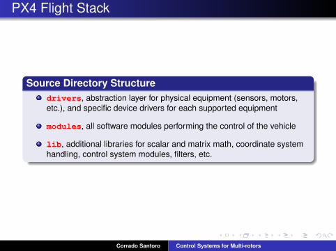
Source Directory Structuredrivers, abstraction layer for physical equipment (sensors, motors,etc.), and specific device drivers for each supported equipment
modules, all software modules performing the control of the vehicle
lib, additional libraries for scalar and matrix math, coordinate systemhandling, control system modules, filters, etc.
Corrado Santoro Control Systems for Multi-rotors
PX4 Driver Layer
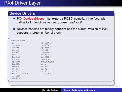
Device DriversPX4 Device drivers must export a POSIX-compliant interface, withcallbacks for functions as open, close, read, ioctl
Devices handled are mainly sensors and the current version of PX4supports a large number of them:�
./src/drivers:gps mpu6050__hc_sr04 mpu6500hmc5883 mpu9250irlock ms5611l3gd20 oreoledled pca8574lis3mdl pca9685ll40ls pwm_inputlps22hb pwm_out_simlsm303d sf0xlsm6ds33 sf10amb12xx srf02md25 srf02_i2cmeas_airspeed uart_escmpu6000mpu6050� �
Corrado Santoro Control Systems for Multi-rotors
PX4 Device Driver and Sensors
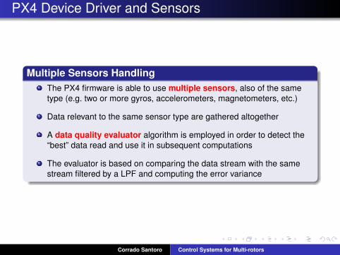
Multiple Sensors HandlingThe PX4 firmware is able to use multiple sensors, also of the sametype (e.g. two or more gyros, accelerometers, magnetometers, etc.)
Data relevant to the same sensor type are gathered altogether
A data quality evaluator algorithm is employed in order to detect the“best” data read and use it in subsequent computations
The evaluator is based on comparing the data stream with the samestream filtered by a LPF and computing the error variance
Corrado Santoro Control Systems for Multi-rotors

PX4 Modules
The modules directoryPX4 modules are the main control blocks of the autopilot
Each module is a NuttX task that is started at system startup andimplements an infinite loop performing the activities:
1 waiting for the sampling period2 retrieving subscribed data from uORB3 executing the specific computation4 publishing the result to uORB
Corrado Santoro Control Systems for Multi-rotors

PX4 Modules
The modules directoryModules include:
attitude estimator ekf, EKF for attitude estimationattitude estimator q, complementary filter for attitude estimationcommander, sensor calibration routines and GCS command handling(through MAVLink)ekf att pos estimator, EKF for position and attitude estimationfw att control, attitude (and rate) controllers for fixed-wing UAVsfw pos control l1, position controllers for fixed-wing UAVsmavlink, MAVLink protocol routinesmc att control, attitude (and rate) controllers for multirotor UAVsmc pos control, position controllers for multirotor UAVsnavigator, controller for handling autonomous missionssdlog2, the loggersegway, attitude controllers for a segwaysystemlib, system modules, including the mixer
Corrado Santoro Control Systems for Multi-rotors
The CDrone Flight Stack
The CDrone Flight Stack
Corrado Santoro Control Systems for Multi-rotors

CDrone Flight Stack
CDrone BasicsIt is a flight stack developed at the DMI@UNICT for educationalpurposes
Initially designed in C for Microchip dsPIC33F family MCUs
Then rewritten in C++ and ported to the STM32 architecture(STM32F401RE)
It runs in bare metal, with a very light HAL layer written in C++
It includes only the basic modules of a UAV control system (those infigure + the MAVLink interface)
Corrado Santoro Control Systems for Multi-rotors

CDrone HAL
Peripheral and Task LayersCDrone is strongly object-based, so everything is defined as a classThe Peripheral layer includes some (abstract and concrete) classeseach representing a specific peripheral
The Task layer includes the abstract class PeriodicTask (the basefor the implementation of any periodic task) and the (non preemptive)scheduler
Scheduling is triggered by a timer running at 400 Hz
Corrado Santoro Control Systems for Multi-rotors

CDrone HAL
Sensor DriversIMU Sensors are represented by a generic IMU abstract class that mustbe extended into the class that implements the code to handle specificsensors
A IMU X NUCLEO class that drives (via I2C) a X-NUCLEO-IKS01A1add-on board
Corrado Santoro Control Systems for Multi-rotors

CDrone HAL
Control System LayerSome (abstract and concrete) classes implementing
the PID algorithm (with derivative low-pass filter, anti-wind-up andfeedforward)some filters, a 2nd order LowPass filter, and a 4nd orderChebysev low-pass filter
Corrado Santoro Control Systems for Multi-rotors

CDrone Flight Control Classes
RemoteControl, interface with the RC
RateControl, angular rate control algorithms
AttitudeControl, control algorithms on Euler angles
AirFrame, abstract class representing an airframe
AirFrameQuadX, class representing an X-shaped quadcopter
AHRS, abstract class representing a generic sensor fusion algorithm
ComplementaryFilter, the complementary filter sensor fusion algorithm
DCM, the DCM sensor fusion algorithm
MAVLinkReceiver, MAVLink command handler
Corrado Santoro Control Systems for Multi-rotors

CDrone: Statistics
Loop-time: 2.5ms
I2C Sensor Polling: 930µs
DCM Sensor Fusion, Rate and Attitude Control: 410µs without FPU
DCM Sensor Fusion, Rate and Attitude Control: 290µs with FPU
Total processing time: 1.34ms without FPU
Total processing time: 1.22ms with FPU
Corrado Santoro Control Systems for Multi-rotors

CDrone TO-DO List
Re-designing/modifying the current airframe, it seems vibratingtoo much
Porting the software to the STM32F7 flight control board
Including altitude control, with barometric and ultrasonic sensors
Including other form of navigation/stabilisationGPSCamera...
Corrado Santoro Control Systems for Multi-rotors

Control Systems for Multi-rotorsPrinciples, Modeling and Software Design
Corrado Santoro
ARSLAB - Autonomous and Robotic Systems LaboratoryDipartimento di Matematica e Informatica - Universita di Catania, Italy
Corrado Santoro Control Systems for Multi-rotors


