Composite Repair Methods for Steel Pipes
by
Dr. Ozden O. Ochoa, Professor Department of Mechanical Engineering
Texas A&M University
Chris Alexander Stress Engineering Services, Inc.
Final Project Report Prepared for the Minerals Management Service
Under the MMS/OTRC Cooperative Research Agreement 1435-01-04-CA-35515
Task Order 39300 MMS Project Number 558
June, 2007

OTRC Library Number: 12/07A184
“The views and conclusions contained in this document are those of the authors and should not be interpreted as representing the opinions or policies of the U.S. Government. Mention of trade names or commercial products does not constitute their endorsement by the U. S. Government”.
For more information contact:
Offshore Technology Research Center Texas A&M University
1200 Mariner Drive College Station, Texas 77845-3400
(979) 845-6000
or
Offshore Technology Research Center The University of Texas at Austin
1 University Station C3700 Austin, Texas 78712-0318
(512) 471-6989
A National Science Foundation Graduated Engineering Research Center
TABLE OF CONTENTS EXECUTIVE SUMMARY ................................................................................................ 1
BACKGROUND ................................................................................................................ 2
INTRODUCTION .............................................................................................................. 4
DESIGN AND DEVELOPMENT...................................................................................... 6
INSTALLATION AND IMPLEMENTATION................................................................. 9
OPERATIONS AND MAINTENANCE.......................................................................... 11
CONCLUSIONS............................................................................................................... 12
REFERENCES ................................................................................................................. 14
Appendix A - Recommended Tests ................................................................................ A-1
Appendix B – Workshop Proceedings............................................................................ B-1
Appendix C – Workshop Presentations .......................................................................... C-1

DEVELOPMENT OF GUIDELINES FOR THE REPAIR OF RISERS USING COMPOSITE MATERIALS
EXECUTIVE SUMMARY
For the past decade the use of composite materials in repairing offshore systems has been
of interest to operators and regulators. Risers are one of the most important elements in
an offshore system and are often susceptible to damage and degradation including outside
impact and corrosion. While risers have been repaired using composite materials, to date
there has not been a program to specifically assess the use of this technology relative to
mechanical integrity requirements. For this reason MMS sponsored a research program
starting in 2006 with the Offshore Technology Research Center (OTRC) to assess
existing composite repair technology. One primary aim of this work was to develop
guidelines to assist regulators, operators, and manufacturers in using composite
technology to repair risers.
The development of this guideline is based on findings of the funded research that also
involved co-sponsored research activities from four manufacturers in the form of a joint
industry project (JIP). The aim of this document is to provide guidance to industry in
terms of the following areas: (1) design and development, (2) installation and
implementation, and (3) operations and maintenance. The sections that follow provide
details on each of these areas, with each serving a critical role in the deployment of
effective repairs for long-term service.
Also included is information presented and gathered at a workshop hosted by the OTRC
at Stress Engineering Services, Inc. in Houston, Texas on March 29, 2007. The workshop
was attended by representatives from MMS and other regulatory bodies, academia and
research organizations, oil and gas companies, service/consulting firms, and composite
repair manufacturers. A beneficial exchange of information and ideas took place as
participants learned about the background of composite repairs as well as the critical
aspects of integrating this technology for the repair of offshore risers.
- 1 -
BACKGROUND
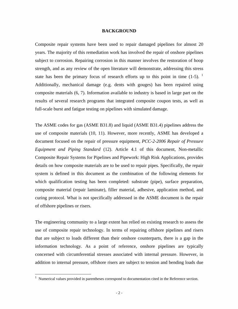
Composite repair systems have been used to repair damaged pipelines for almost 20
years. The majority of this remediation work has involved the repair of onshore pipelines
subject to corrosion. Repairing corrosion in this manner involves the restoration of hoop
strength, and as any review of the open literature will demonstrate, addressing this stress
state has been the primary focus of research efforts up to this point in time (1-5). 1
Additionally, mechanical damage (e.g. dents with gouges) has been repaired using
composite materials (6, 7). Information available to industry is based in large part on the
results of several research programs that integrated composite coupon tests, as well as
full-scale burst and fatigue testing on pipelines with simulated damage.
The ASME codes for gas (ASME B31.8) and liquid (ASME B31.4) pipelines address the
use of composite materials (10, 11). However, more recently, ASME has developed a
document focused on the repair of pressure equipment, PCC-2-2006 Repair of Pressure
Equipment and Piping Standard (12). Article 4.1 of this document, Non-metallic
Composite Repair Systems for Pipelines and Pipework: High Risk Applications, provides
details on how composite materials are to be used to repair pipes. Specifically, the repair
system is defined in this document as the combination of the following elements for
which qualification testing has been completed: substrate (pipe), surface preparation,
composite material (repair laminate), filler material, adhesive, application method, and
curing protocol. What is not specifically addressed in the ASME document is the repair
of offshore pipelines or risers.
The engineering community to a large extent has relied on existing research to assess the
use of composite repair technology. In terms of repairing offshore pipelines and risers
that are subject to loads different than their onshore counterparts, there is a gap in the
information technology. As a point of reference, onshore pipelines are typically
concerned with circumferential stresses associated with internal pressure. However, in
addition to internal pressure, offshore risers are subject to tension and bending loads due
1 Numerical values provided in parentheses correspond to documentation cited in the Reference section.
- 2 -

to their suspended nature in the water. For this reason, any composite system used to
repair offshore risers should address these loading conditions to ensure that the system
performs as intended. Several operators have used composite materials to repair offshore
risers (13). In spite of the use of this repair technique, many in the industry recognize the
need for additional research to address the use of composite materials in repairing
offshore riser systems. Through additional investigations, industry will gain insights
regarding the capabilities and limitations that exist with current composite technology.
- 3 -

INTRODUCTION
As stated previously, this guideline is intended to be a resource for regulators, operators,
and manufacturers. To effectively assess composite technology, and in particular any
specific repair system, it is important to divide the assessment process into several
specific subject areas. The first involves design and development. This subject area
involves ensuring that the composite technology has been designed with the appropriate
service conditions in mind, and most importantly, that the manufacturer has properly
addressed and accounted for factors that can lead to inadequate performance and long-
term degradation. It is the responsibility of the manufacturer to ensure that the design of
their particular system meets minimum design and service requirements. It is recognized
that enforcement and performance requirements will likely come from operators and
regulators. The second subject area concerns installation and implementation. History has
shown that even with the best designs, when technology is not properly used the potential
for sub-standard performance exists, sometimes with catastrophic results. For this reason,
guidelines are provided herein to ensure that the repair of risers is done correctly, with an
emphasis on quality assurance and consistent methodology. The third subject area
concerns operations and maintenance. Once the composite materials have been installed,
it is important for operators to conduct periodic inspections and perform maintenance as
appropriate. Long-term performance is directly related to how well the composite
materials are protected and maintained. Failure to properly maintain these repair systems
will result in sub-standard performance.
The sections that follow provide specific discussions on the three above-mentioned
subject area topics. While not overly-prescriptive, the intent is to provide general
guidelines to be used by industry to assess existing technology and develop new
composite repair systems as required to address the ever-increasing demands of offshore
conditions (such as deep water applications). In large part, these guidelines are a direct
result of insights gained in performing tests associated with the MMS-sponsored JIP
program.
- 4 -
Several appendices are provided that provide specific information. Appendix A provides
a list of recommended material testing that should be performed to assess the
performance of any repair system used to repair offshore risers. In Appendix B one finds
the proceedings of the workshop on repair of risers using composite materials, Repair of
Risers Using Composite Materials Workshop, held at Stress Engineering Services, Inc. on
March 29, 2007. The final appendix, Appendix C, contains copies of the presentations
made at the workshop.
- 5 -
DESIGN AND DEVELOPMENT
From a recommendation standpoint, this guideline does not favor any one particular
composite repair technology over another. It is recognized that whether a manufacturer
elects to use carbon or E-glass, epoxy resin or urethane, or pre-cured or in situ cured, the
reason for doing so will largely be determined by technology requirements and economic
viability. However, it is possible to provide guidelines that specifically address
technology requirements when composite materials are used to repair offshore risers.
The sections that follow provide a list of design requirements, as well as
recommendations for manufacturers to consider in documenting that their particular
system satisfies the appropriate design requirements.
Design Requirements
The list below captures design elements that should be specifically addressed by
manufacturers in the development of their system. The primary means of verifying that a
particular system meets the design requirements should involve full-scale testing,
preferably efforts that involve testing to failure in order to determine the limit capacity
for a particular repair system.
1. Loading assessment – the composite repair system should be designed to provide
adequate reinforcement to the steel riser pipe considering all possible loads. As a
minimum, these loads should include internal pressure, tension, and bending. Other
possible load requirements include impact from external forces, and fatigue loading.
2. Allowable stress and strain states – the composite system must evaluate the
performance of two components: the repaired steel and the composite reinforcing
material. Using available design codes such as API RP 1111 and ASME B31.8, the
system must ensure that stresses and strains within each respective component are
less than a specified maximum value. As a point of reference, consider the following:
- 6 -

a. Steel riser material – once the repair is installed, the stress (or strain) in the
steel should be reduced when subjected to increased loading to the point
where plasticity initiates in the steel due to increased compliance. To increase
the level of reinforcement, conventional methods employ a composite with
greater stiffness by either increasing the composite thickness or selecting a
material having a greater elastic modulus.
b. Composite material – unlike steel whose mechanical properties do not
degrade over time due to sustained loading, the properties of composite
systems can degrade over time (often due to degradation of the resin). For this
reason, any repair using composite materials must consider the degraded long-
term strength as part of the design. By designing so that the stress in the
composite material is less than a specified threshold, long-term performance is
enhanced.
3. Material qualification – composite materials are identified based on their particular
constituent components including fiber and matrix selection. Material qualification is
a critical aspect of the design process. Appendix A provides a list of the
recommended tests based on ASTM procedures.
4. Repair life – the design of the repair system should adequately address long-term
performance requirements. This includes accounting for all load types, environmental
effects, and material degradation.
5. Geometry of repair – the geometry of the repair should be based on sound
engineering principles. The governing factors for the design include the extent of
damage to the riser (e.g. corrosion depth and length) and material properties of the
composite including stiffness, tensile strength, elongation to failure, and adhesive lap
shear strength. These factors will be used to determine the thickness and length of the
repair.
- 7 -
6. Type of repair – it is important as part of these guidelines to establish what
constitutes an acceptable repair. External corrosion associated with general material
loss and dents and scratches are covered as part of this guideline. It should be noted
that whatever defect is repaired, applicable design and fitness for service codes
should be referenced to ensure that the repair of inappropriate defects does not occur.
This guideline does not encourage or endorse the repair of leaking defects.
7. Environmental and operating factors – the design of the composite repair should
properly address all potential environmental and operating factors. Examples include
UV exposure, wet/dry conditions, elevated temperatures and temperature extremes,
long-term exposure to sea water, and potential for exposure to aggressive chemicals.
It is noted that the composite repair systems maybe exposed to fire and open flames.
This can be mitigated by additives in the resin and external fire retardant coatings for
fire. In areas where exposure to fire is possible, it is important that this be done. Even
if the composite repair system does not catch fire, exposure to elevated temperatures
will result in loss of strength which could result in failure of the repair, possibly
leading to catastrophic failure of the repaired piping.
8. Susceptibility to damage – although perhaps more related to discussions on
operations and maintenance, the design process should consider the effects of external
damage and how a particular system not only withstands damage, but also how the
system can be repaired if necessary. Part of this process involves assessing damage
tolerance before issues arise in the field.
- 8 -

INSTALLATION AND IMPLEMENTATION
The successes and failures in using composite materials to repair pipelines in the field
have largely been related to issues associated with installation and implementation. When
the repair systems are installed correctly according to the manufacturer’s
recommendations, they typically perform as designed. However, when improper
installation techniques are used, the likelihood for inadequate performance is
significantly increased. This section of the guideline is intended to help manufacturers
develop appropriate installation techniques, as well as providing for operators and
regulators key points of interest to monitor during the installation of repairs.
Provided below is a list of important topics associated with the installation of composite
repair systems offshore.
1. Documentation – it is important that manufacturers have documentation available for
operators and regulators that covers the following subject matters:
a. Material performance data including MSDS sheets
b. Details on design basis and testing program
c. Quality control procedures including material traceability and tracking
d. Installation procedures with details as appropriate including minimum cure
times
e. Forms for detailing specific elements of the repair procedure and how the
repair conforms to manufacturer’s recommendations.
2. Installation procedures – to ensure quality installation, it is important that
installation procedures be developed so that each repair is performed consistently and
in a manner that meets certain workmanship standards. Additionally, the procedures
should provide details on what to do when untoward conditions occur during
installation. An example includes what to do when a resin does not cure in the
appropriate time period.
- 9 -
3. Assessing quality of installation – this has historically been the primary problem
with field installation of composites. When failures have occurred, they most often
involve the improper allocation of resin and also using resins that fail to cure. When
either of these conditions exists, the performance of the repair will not meet minimum
requirements. Operators and regulators should ensure that the resins have been
properly installed and that curing has occurred as specified by the manufacturer.
- 10 -
OPERATIONS AND MAINTENANCE
Unlike buried pipelines where repairs are largely unseen, offshore repairs are exposed to
the elements including weather, sea conditions, and the possibility for impact with
outside forces. For this reason, it is recommended that periodic inspection of the repairs
be made when possible. Provided below are examples of some facets of the repairs that
should be inspected:
1. Inspecting for external damage associated with impact.
2. Looking at the ends of the repair to assess the possibility for moisture ingression.
3. Evaluating if any loads have been applied to the repair that exceed the original design
values (this is especially important in hurricane conditions).
4. On a periodic basis, selected regions of the repair should be inspected for possible
delamination.
5. If the repair has been painted to protect against exposure from UV light, inspection
should ensure that no exposed surfaces exist.
6. Operators should document inspection efforts as part of a formal fitness for purpose
inspection program.
7. If sub-standard conditions are found to exist, the composite system should be repaired
(if possible), or replaced if remediation options do not exist.
- 11 -

CONCLUSIONS
Due to the complex loads associated with repairing risers, the offshore industry has been
cautious and methodical in accepting the use of composite materials as a means for
reinforcing corroded and damaged risers. It is possible, under the right conditions, that
composite materials can be used to repair offshore risers in the area of splash zone. In
order for this to take place, the user must have a clear understanding of the loads
imparted to the riser and be technically confident that the selected composite materials
can provide an adequate level of reinforcement.
The fundamental objective of this effort has been demonstrated in the four-team JIP
program conducted by Stress Engineering Services, Inc. This full scale test program
evaluated four different composite repair systems. The program incorporated 8.625-inch
x 0.406-inch, Grade X46 pipe test samples that were fitted with simulated corrosion by
machining. The program involved destructively testing three samples repaired by each
respective composite repair system. The three tests included a burst test (increasing
pressure to failure), a tension to failure test (pressure with increasing axial tension loads
to failure), and a four-point bend test (pressure and tension held constant with increasing
bending loads to achieve significant yielding in steel).
It should be recognized that the primary purpose of the JIP study was to identify and
confirm the critical elements required for an effective composite repair. Having
practically unlimited access to manufacturers with the ability to understand the overall
mechanics of each repair, the author was provided with insights useful for developing an
optimized repair system. Other benefits were also derived in the execution of the
program, including the development of guidelines for industry and regulators and
providing the manufacturers with the opportunity to assess their repair systems relative to
loading conditions associated with offshore risers. In using composite materials to
reinforce damaged and corroded risers, it is critical to integrate a design methodology that
assesses the strain in the reinforced steel. This is especially important in offshore design
as risers in the splash zone are subjected to combined loads including internal pressure,
- 12 -

axial tension, and bending loads, as compared to onshore repairs that primarily involve
restoration of hoop strength. As has been demonstrated in this presentation, use of strain
based design methods is the ideal approach for assessing the interaction of load transfer
between the reinforced steel and the reinforcing composite material. Industry should be
cautious of any design methodology that does not capture the mechanics associated with
the load transfer between the steel and composite materials during the process of loading.
The two keys are to first determine strain limits based on acceptable design margins, and
then assess strain levels in both the steel and composite reinforcement using either
analysis methods, or the preferred approach involving full-scale testing with strain gages
- 13 -
REFERENCES
1. Pipeline Safety: Gas and Hazardous Liquid pipeline Repair, Federal Register, Vol.
64, No. 66, Wednesday, April 7, 1999, Proposed Rules, Department of Transportation, Research and Special Programs Administration, Docket No. RSPA-98-4733, Notice 1.
2. Fawley, N. C., Development of Fiberglass Composite Systems for Natural Gas Pipeline Service, Final Report prepared for the Gas Research Institute, GRI-95/0072, March 1994.
3. Stephens, D. R. and Kilinski, T. J., Field Validation of Composite Repair of Gas Transmission Pipelines, Final Report to the Gas Research Institute, Chicago, Illinois, GRI-98/0032, April 1998.
4. Kuhlman, C. J., Lindholm, U. S., Stephens, D. R., Kilinski, T. J., and Francini, R. B., Long-Term Reliability of Gas Pipeline Repairs by Reinforced Composites, Final Report to the Gas Research Institute, Chicago, Illinois, GRI-95/0071, December 1995.
5. Block, N., and Kishel, J., Clock Spring® Reinforcement of Elbow Fittings, Topical Report prepared for the Gas Research Institute, GRI-93/0346, December 1995.
6. Alexander, C. R., Pitts, D. A., Evaluation of the AquawrapTM System in Repairing Mechanically-damaged Pipes, report prepared for Air Logistics Corporation, Azusa, California, September 2005.
7. Alexander, C.R., Wilson, F.D., Recent Test Results and Field Experience with Armor Plate® Pipe Wrap Repairing Corroded and Mechanically-Damaged Pipes, 2000 Pigging Conference, Houston, Texas, February 2000.
8. Pipeline Safety: Gas and Hazardous Liquid pipeline Repair, Federal Register, Vol. 64, No. 239, Tuesday, December 14, 1999, Rules and Regulations, Department of Transportation, Research and Special Programs Administration, Docket No. RSPA-98-4733; Amdt. 192-88; 195-68 (Effective date: January 13, 2000).
9. American Society of Mechanical Engineers, Manual for Determining the Remaining Strength of Corroded Pipelines, ASME B31G-1991, New York, New York, 1991 edition.
10. American Society of Mechanical Engineers, Gas Transmission and Distribution Piping Systems, ASME B31.8, New York, New York, 2003 edition.
11. American Society of Mechanical Engineers, Liquid Transportation System for Hydrocarbons, Liquid Petroleum Gas, Anhydrous Ammonia and Alcohols, ASME B31.4, New York, New York, 2003 edition.
12. PCC-2-2006 Repair of Pressure Equipment and Piping Standard, ASME, New York, New York, 2006 edition.
13. Personal communication with Mr. Paul Moise of Armor Plate, Inc., September 2006.
- 14 -

Appendix A - Recommended Tests
Page A-1
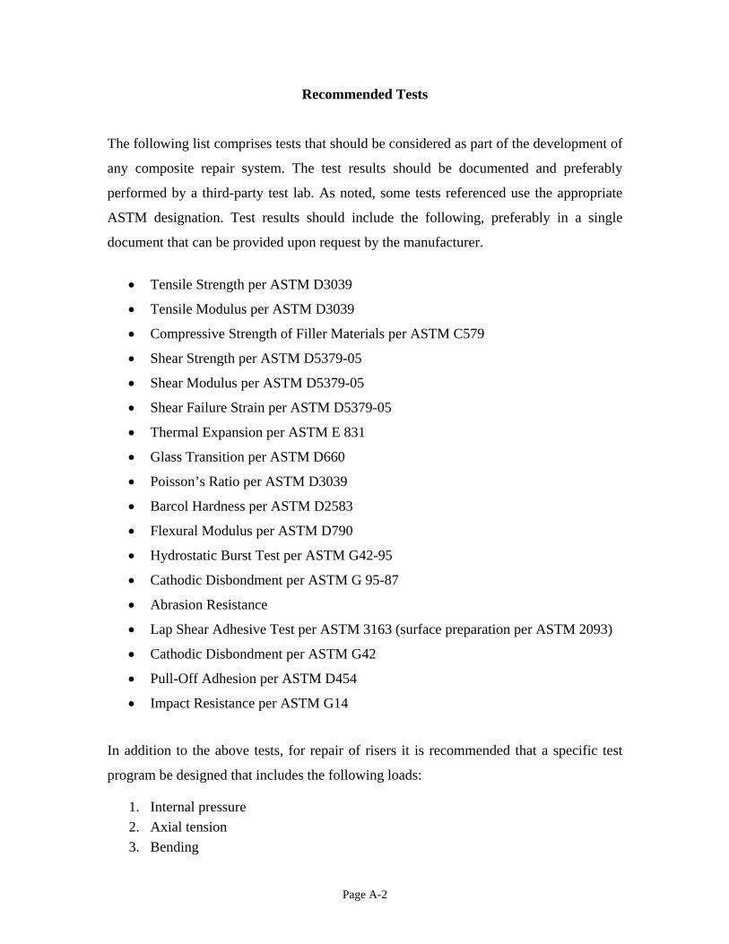
Recommended Tests
The following list comprises tests that should be considered as part of the development of
any composite repair system. The test results should be documented and preferably
performed by a third-party test lab. As noted, some tests referenced use the appropriate
ASTM designation. Test results should include the following, preferably in a single
document that can be provided upon request by the manufacturer.
• Tensile Strength per ASTM D3039
• Tensile Modulus per ASTM D3039
• Compressive Strength of Filler Materials per ASTM C579
• Shear Strength per ASTM D5379-05
• Shear Modulus per ASTM D5379-05
• Shear Failure Strain per ASTM D5379-05
• Thermal Expansion per ASTM E 831
• Glass Transition per ASTM D660
• Poisson’s Ratio per ASTM D3039
• Barcol Hardness per ASTM D2583
• Flexural Modulus per ASTM D790
• Hydrostatic Burst Test per ASTM G42-95
• Cathodic Disbondment per ASTM G 95-87
• Abrasion Resistance
• Lap Shear Adhesive Test per ASTM 3163 (surface preparation per ASTM 2093)
• Cathodic Disbondment per ASTM G42
• Pull-Off Adhesion per ASTM D454
• Impact Resistance per ASTM G14
In addition to the above tests, for repair of risers it is recommended that a specific test
program be designed that includes the following loads:
1. Internal pressure 2. Axial tension 3. Bending
Page A-2

The test program should ensure that the composite repair system reduces strains in the
repaired section of the steel test pipe to below a specified level.
Additionally, it is critical that the composite repair system demonstrate adequate long-
term performance for the intended design life.
Page A-3
Appendix B – Workshop Proceedings
Page B-1

Repair of Risers Using Composite Materials Workshop
by
Dr. Ozden O. Ochoa, Professor Department of Mechanical Engineering
Texas A&M University
Chris Alexander Stress Engineering Services, Inc.
Workshop Proceedings Prepared for the Minerals Management Service
Under the MMS/OTRC Cooperative Research Agreement 1435-01-04-CA-35515
Task Order 39300 MMS Project Number 558
March 29, 2007
OTRC Library Number: 4/07CPWS
“The views and conclusions contained in this document are those of the authors and should not be interpreted as representing the opinions or policies of the U.S. Government. Mention of trade names or commercial products does not constitute their endorsement by the U. S. Government”.
For more information contact:
Offshore Technology Research Center Texas A&M University
1200 Mariner Drive College Station, Texas 77845-3400
(979) 845-6000
or
Offshore Technology Research Center The University of Texas at Austin
1 University Station C3700 Austin, Texas 78712-0318
(512) 471-6989
A National Science Foundation Graduated Engineering Research Center

Table of Contents Table of Contents................................................................................................................. i
Executive Summary ............................................................................................................ 1
Background and Objectives ............................................................................................ 1 Workshop Organization .................................................................................................. 1
Recommendations............................................................................................................... 2
Acknowledgements............................................................................................................. 3
Appendix A......................................................................................................................... 5
Workshop Agenda .......................................................................................................... 5 Workshop Participants .................................................................................................... 5
i
Repair of Risers Using Composite Materials Workshop
O. O. Ochoa, Texas A&M University C. Alexander, Stress Engineering Services, Inc.
Executive Summary
Background and Objectives
This one day workshop shared the results of an MMS sponsored research project at OTRC focused on developing guidelines to assist regulators, operators, and manufacturers in using composite technology to repair steel risers and tubulars.
Glass reinforced polymer systems have been routinely used to repair corrosion damaged onshore pipelines in the last two decades. These repair systems restore hoop strength. However in addition to internal pressure, offshore risers and pipelines are subject to tension and bending loads, and thus require an extension of repair performance to address combined loading.
The objective of the workshop was to introduce and discuss a recommended repair approach and metrics that addressed:
i. Design and development ii. Installation and implementation
iii. Operation and maintenance
The workshop presentations and discussions highlighted the assessment of existing technology as well as development of new composite repair systems for future deep water considerations.
Workshop Organization The workshop was initiated and sponsored by OTRC/MMS as a required task outlined in MMS Project 558 “Composite Repair Methods for Steel Pipes”. The workshop was hosted by Stress Engineering Services, Inc., 13800 Westfair East Drive, Houston, TX 77041 and carried out by Chris Alexander, Principal, Stress Engineering, and Dr. Ozden Ochoa, Texas A&M University. The one-day workshop was held March 29, 2007 and was well attended. The 34 participants represented a wide range of perspectives and experience. The workshop agenda and list of workshop participants are shown in Appendix A. The morning session included the following presentations:
1

• Dr. E. G. Ward, OTRC – Dr. Ward’s presentation covered OTRC background
with extended emphasis on advanced materials research as shown in Appendix B. • Lori Medley, MMS – Ms. Medley spoke briefly concerning the Gulf of Mexico’s
anticipation of the workshop and project results • Dr. Ozden Ochoa, TAMU – Dr. Ochoa’s presentation covered the possibilities of
using composites in offshore applications as shown in Appendix C. • Chris Alexander, Stress Engineering Services, Inc. – Mr. Alexander’s
presentation covered the fundamentals of composite repair and outlined recent test results. Chris’ presentation also included discussions of the four team joint industry project conducted at Stress Engineering. Brent Vyvial, Stress Engineering, assisted Mr. Alexander with the discussion of the JIP test procedures and results. The full presentation is shown in Appendix D.
The afternoon session included a tour of the Mohr Engineering test facility and provided an opportunity for workshop participants to view the test samples of the JIP participants as well as interact with representatives from the four companies which participated in the JIP. Following the tour, Chris Alexander passed out a survey to workshop participants asking for feedback from the participants concerning their status and desire for the use of composites for pipeline/riser repair within their companies. An open discussion followed where technology/information gaps were identified so that a path forward for future work could be developed.
Recommendations Based on a review of current industry practices and recognizing the potential role that composite materials will serve in the future of repairing offshore risers and pipelines, the following recommendations are provided. It should be noted that before industry-wide acceptance of this repair technology occurs, additional investigations are required. Addressing issues such as long-term performance is necessary to ensure that this technology functions as intended in restoring the serviceability to damaged offshore risers and pipelines.
1. It is necessary to develop definitive design guidelines in terms of allowable strains for both the reinforced steel and composite materials. The design document must take into account all modes of loading typical for offshore risers including internal pressure, tension, and bending. A limit state design methodology is recommended. Satisfying only the requirements for hoop strength is not sufficient. Additionally, design requirements should take into account reductions in strength and stiffness as functions of time and other environmental factors such as environmental exposure.
2. Performance testing is required to prove the viability of composite repair
technology. While analysis can serve as the basis for the design, each composite
2
system used to repair risers and pipelines must be tested to establish performance capabilities.
3. Quality control of installation methods and materials is required. Personnel who
are actually installing the repair materials must be trained and certified by the manufacturer or a representative party. Documentation must exist to ensure that minimum quality standards are maintained.
4. The composite repair system must be evaluated as part of an overall
comprehensive testing program. Testing must be in accordance with industry norms and third party verification is encouraged.
5. To ensure long-term performance, a major focus of the overall testing program
should involve assessing potential degradation mechanisms. This is especially important in offshore service where the test program should assess changes in strength as a function of time under loaded conditions. Demonstration of short-term strength is necessary, but not sufficient to establish long-term performance.
Acknowledgements
This workshop was an element of an Offshore Technology Research Center Project funded by the Minerals Management Service. Their sponsorship is gratefully acknowledged. Special thanks to Stress Engineering Services, Inc. for hosting the workshop and for coordinating the tour at neighboring Mohr Engineering. Thank you to the four Joint Industry Project participants for allowing workshop participants to view samples of their test results: Air Logistics Corporation Mr. Franz Worth 925 North Todd Avenue Azusa, CA 91702 Phone: 626-633-0294 E-mail: [email protected] Armor Plate, Inc. Mr. Tony Wilson, President P.O. Box 5625 Pasadena, Texas 77508-5625 Phone: (281) 487-2023 E-mail: [email protected]
3

Comptek Structural Composites Mr. Jim Lockwood, CEO 1966 13th Street, Suite 280 Boulder, Colorado 80302 Phone: 720-304-6882 Email: [email protected] Pipe Wrap LLC Ms. Gen Withers, CEO P.O. Box 270190 Houston TX 77277-0190 Phone: 713-365-0881 Fax: 713-463-4459 Email: [email protected]
4

Appendix A
Workshop Agenda
8:30 – 8:45 Check-in and breakfast
8:45 – 9:00 Welcome and introductions (SES and OTRC)
9:00 – 9:15 Regulation perspectives and need for guidelines (MMS)
9:15 – 9:45 Use of composite materials in offshore applications (TAMU)
9:45 – 10:30 Fundamentals of composite repairs (SES)
10:30 – 10:45 Break
10:45 – 11:30 Discussions on Four Team Joint Industry Project (JIP) and introduction of composite repair companies (SES)
11:30 – 12:15 Lunch break
12:15 – 1:30 Tour of Mohr Engineering test facility and viewing of composite repair test samples from JIP program
1:30 – 2:15 Open group discussion on guideline development (OTRC/SES)
2:15 – 2:30 Closing remarks
Workshop Participants Name Affiliation Chris Alexander Stress Engineering Services, Inc. Lawrence Borski Williams Gas Pipe Jaime Buitrago ExxonMobil Upstream Research Co. Robert Campbell ExxonMobil Upstream Research Co. Zai Chang Chevron Gautam Chaudhury BP Ronald Douglas Williams Gas Pipe Ronald Joseph Williams Gas Pipe King Lo Shell International Exploration and Production Inc. James Lockwood Comptek Structural Composites Xiaohua Lu Technip USA Theron C. McLaren US DOT PHMSA Fraser McMaster Chevron ETC Darryl McVeay ExxonMobil Lori Medley Minerals Management Service
5

Paul Moise Armor Plate Inc. Aravind Nair MCS Debbie Oakes Offshore Technology Research Center Ozden Ochoa Texas A&M University Philippe Remacle Total E&P USA, Inc. George Ross Stress Engineering Services, Inc. Ron Scrivner Stress Engineering Services, Inc. Jim Souza Pipe Wrap Brent Vyvial Stress Engineering Services, Inc. Tom Walsh Shell E. G. Ward Offshore Technology Research Center David Weaver Topcoar Offshore Tony Wilson Armor Plate Inc. Gen Withers Pipe Wrap Franz Worth Air Logistics Corp. Jack Wu KBR Qing Yu American Bureau of Shipping Lee Zickefoose Pipe Wrap
6

Appendix C – Workshop Presentations
Page C-1

Offshore Technology Research Center
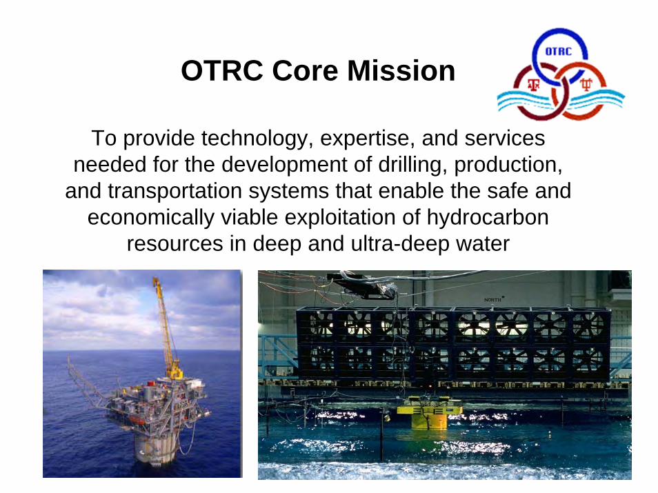
OTRC Core Mission
To provide technology, expertise, and services needed for the development of drilling, production,
and transportation systems that enable the safe and economically viable exploitation of hydrocarbon
resources in deep and ultra-deep water

Offshore Technology Research Center
Partnership:Texas A&M UniversityThe University of Texas at Austin
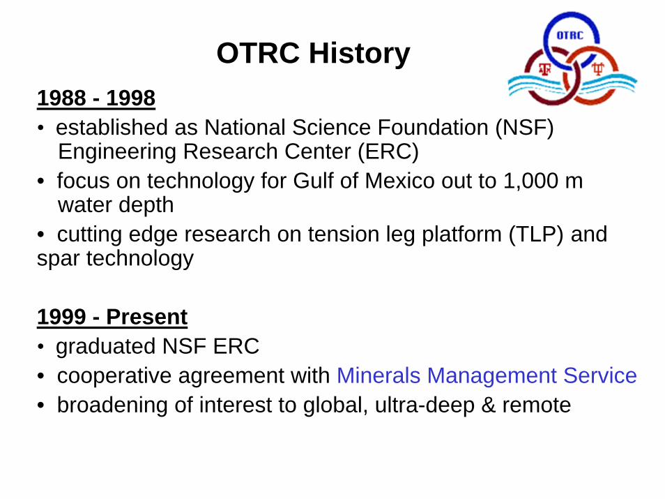
OTRC History1988 - 1998• established as National Science Foundation (NSF)
Engineering Research Center (ERC)• focus on technology for Gulf of Mexico out to 1,000 m
water depth• cutting edge research on tension leg platform (TLP) and spar technology
1999 - Present• graduated NSF ERC • cooperative agreement with Minerals Management Service• broadening of interest to global, ultra-deep & remote

OTRC Mission

Floating Structures
Risers & Moorings
Advanced Materials
Seafloor Engineering
Other Research
OTRC Research Program
FY 2005-2006

Floating Structures
Risers & Moorings
Composite Drilling Riser (NIST)
Coiled Tubing
Qualifying New Technologies for DW Development Workshop
NDE Evaluation Methods for Offshore Composites Workshop
Polyester Mooring Line Damage Model
Polyester Rope Large Scale Experiments JIP
CRA for Composite & Steel Prod. Risers
Composite Riser Experience & Design Guidance
Use of Composite Materials to Repair Pipelines
Advanced Materials
Seafloor Engineering
Other Research
OTRC Research Program
FY 2005-2006

Strength of Damaged Polyester Rope
Strength Loss in Damaged RopesLoss at L/D = 40 vs L/D = 290
40
290
40290
40
290
40
290
-45
-40
-35
-30
-25
-20
-15
-10
-5
0
Rope
Stre
ngth
Los
s as
% U
ndam
aged
St
reng
th
Rope 110%
Rope 410%
Rope 210%
Rope 315%
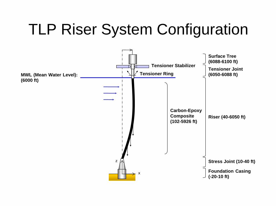
TLP Riser System ConfigurationSurface Tree (6088-6100 ft)Tensioner Joint (6050-6088 ft)
Riser (40-6050 ft)
Stress Joint (10-40 ft)
Foundation Casing (-20-10 ft)
Carbon-Epoxy Composite (102-5926 ft)
MWL (Mean Water Level): (6000 ft)
x
z
Tensioner Stabilizer
Tensioner Ring
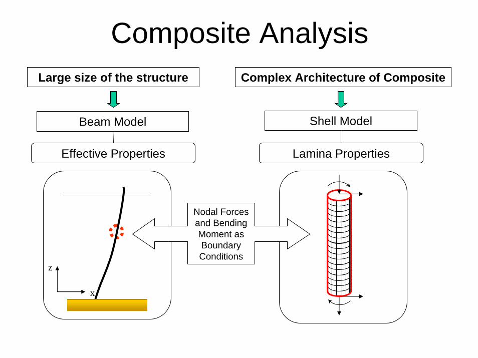
Composite AnalysisLarge size of the structure Complex Architecture of Composite
Beam Model Shell Model
Effective Properties Lamina Properties
x
z
Nodal Forces and Bending Moment asBoundary Conditions

Composite Repairs of Steel Pipes
• Assess currently available composite repair systems for steel pipes
• Test a number of existing repair systems
• Provide practical and useful information to – (1) improve existing systems – (2) expand applicability these
systems to more demanding repair scenarios
Steel Pipeline or Flowline Riser
Clamped to Platform LegPlatform
Leg
Clamp
Waterline
Clamp
Deck
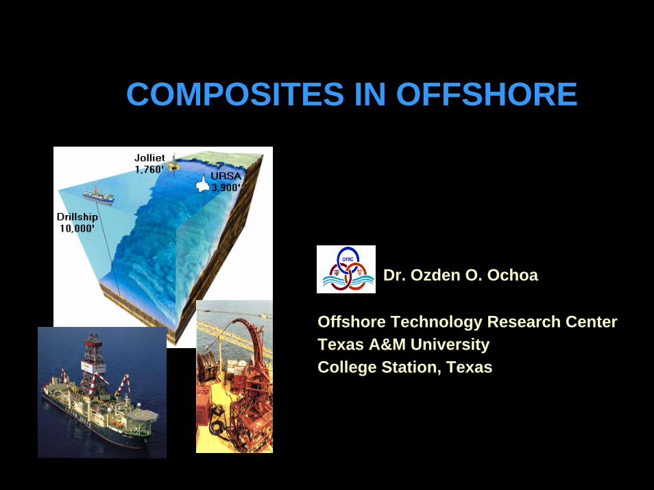
COMPOSITES IN OFFSHORE
Dr. Ozden O. Ochoa
Offshore Technology Research CenterTexas A&M UniversityCollege Station, Texas
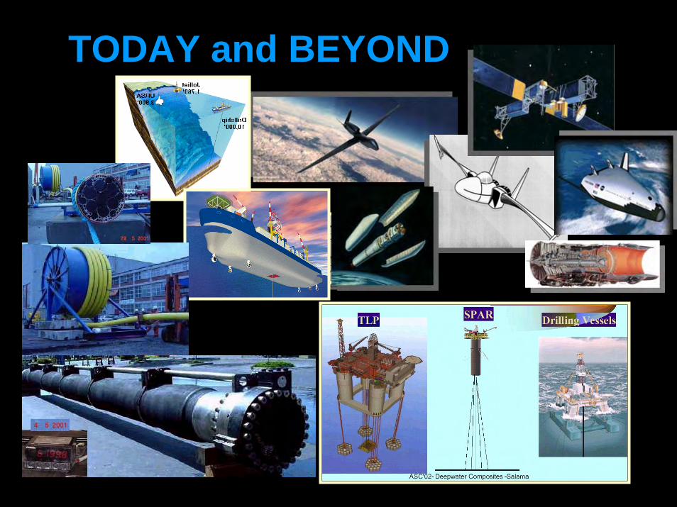
TODAY and BEYOND

RATIONALEDEVELOP
Long Term Durability Philosophyto incorporate physical and chemical material response into service life prediction
COUPONS
RIGID TUBES FLEXIBLE SYSTEMS

SYSTEM BENEFITS
• Providedurabilitydimensional stabilitydamage tolerance
• Accelerate innovative design • Reduce development time and cost• Enable flexible systems
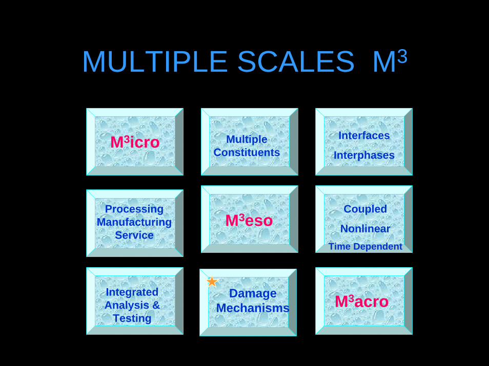
MULTIPLE SCALES M3
Multi-Axial Loads
M3icro
M3acro
Multiple Constituents
Interfaces
Interphases
Coupled
NonlinearTime Dependent
ProcessingManufacturing
Service
Integrated Analysis &
Testing
Damage Mechanisms
M3eso
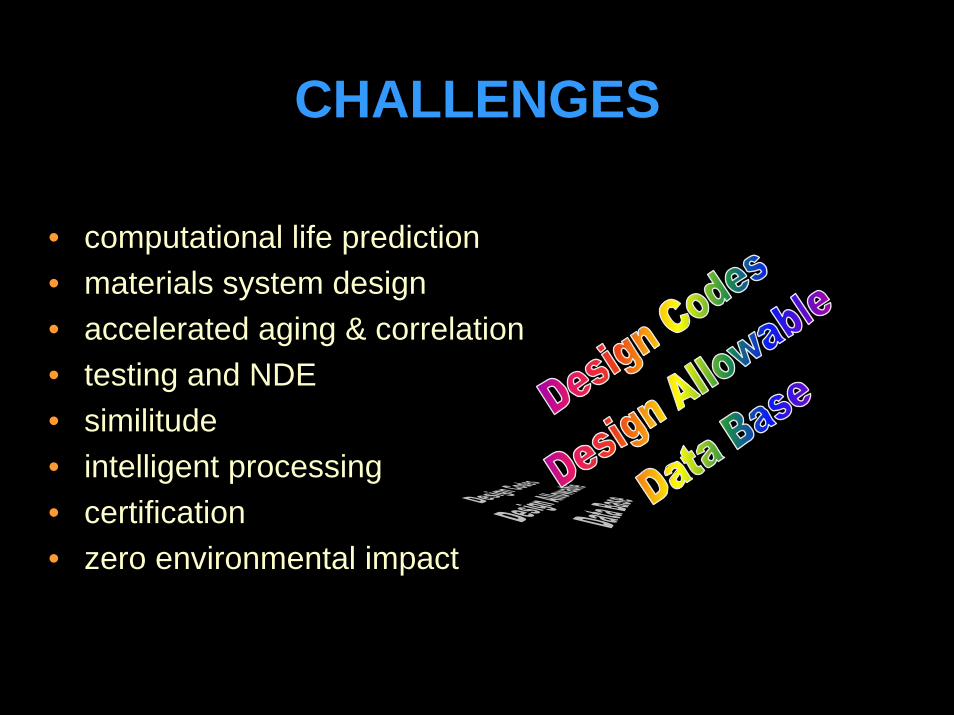
• computational life prediction• materials system design • accelerated aging & correlation• testing and NDE• similitude• intelligent processing• certification• zero environmental impact
CHALLENGES

REQUIREMENTS
• multidisciplinary optimization processingmanufacturingcostperformance
• environmentally acceptable materials
• low cost - high performance trade-off
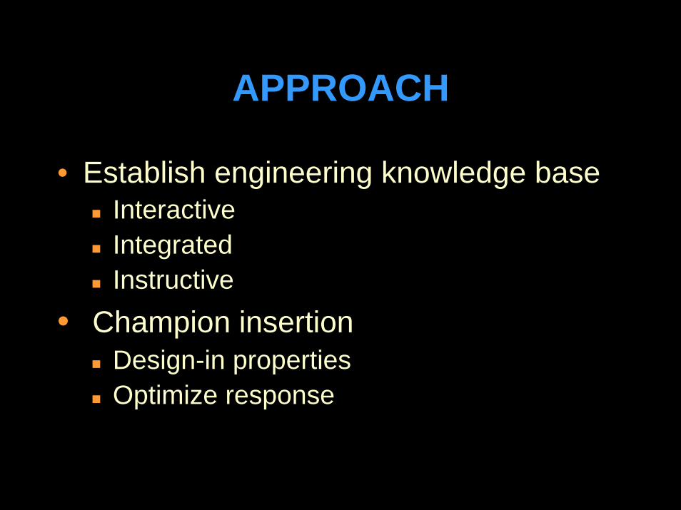
APPROACH
• Establish engineering knowledge baseInteractive IntegratedInstructive
• Champion insertionDesign-in propertiesOptimize response
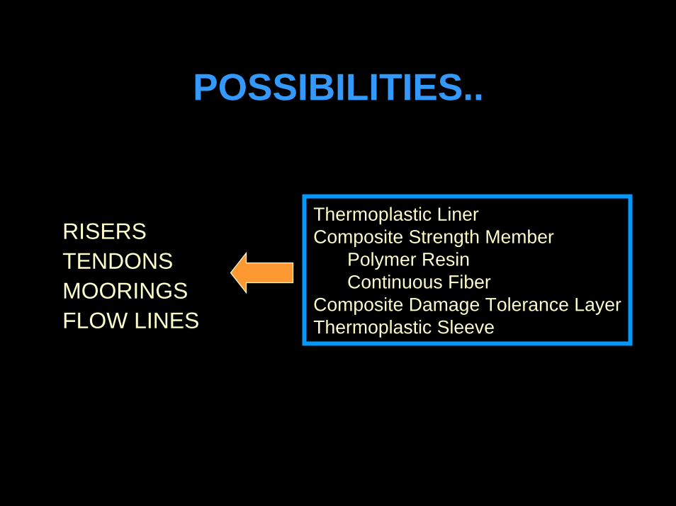
POSSIBILITIES..
RISERSTENDONSMOORINGSFLOW LINES
Thermoplastic LinerComposite Strength Member
Polymer ResinContinuous Fiber
Composite Damage Tolerance LayerThermoplastic Sleeve
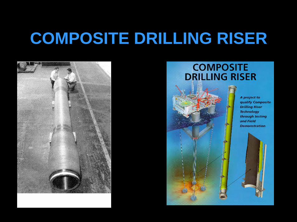
COMPOSITE DRILLING RISER
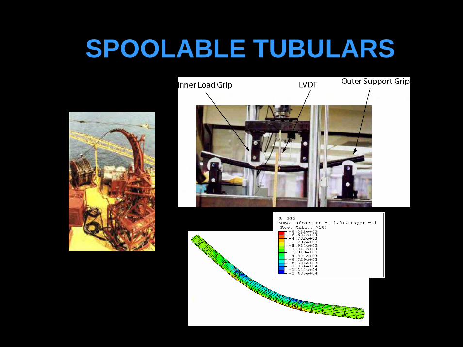
SPOOLABLE TUBULARS
y
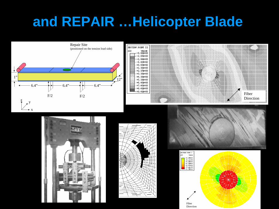
Repair Site(positioned on the tension load side)
x
yzF/2F/2
6.4”
1” 12”6.4” 6.4”
FiberDirection
FiberDirection
and REPAIR …Helicopter Blade

OTRC Reports OchoaComposite Repair Methods For Steel Pipes US DOI Minerals Management Service, 2007
Composite Riser Experience & Design GuidanceUS DOI Minerals Management Service, 2006
Comparative Risk Analysis of Composite RisersUS DOI – Mineral Management Service, 2005
Composite Spoolable TubularsUS DOI Minerals Management Service, 2001
Composite Drilling RisersNIST-ATP, 2000
Response and Reliability of Composite RisersNSF Offshore Technology Research Center 1997-2002

Recent Publications• Kim, W. K., Ochoa, O. O. & Miller, C. A., "Axial and Burst Analysis of Offshore
Composite Risers," 20th Annual Technical Conference of the American Society for Composites, Philadelphia, PA, September 7-9, 2005.
• Kim, W. K. & Ochoa, O. O., "Damage Progression in Composite Production Riser under Combined Loads," 15th International Conference on Composite Materials, Durban, South Africa, June 27 - July 1, 2005.
• Ochoa, O. O. and Salama M. M., “Offshore Composites: Transition Barriers to an Enabling Technology”, J. of Composite Science and Technology, 20th Anniversary Issue, 2005
www.asc-composites.org

OTRC-MMS Workshop on Reinforcing Offshore Risers Using Composite Materials
Thursday, March 29, 2007
Hosted byStress Engineering Services, Inc.
Houston, Texas
2
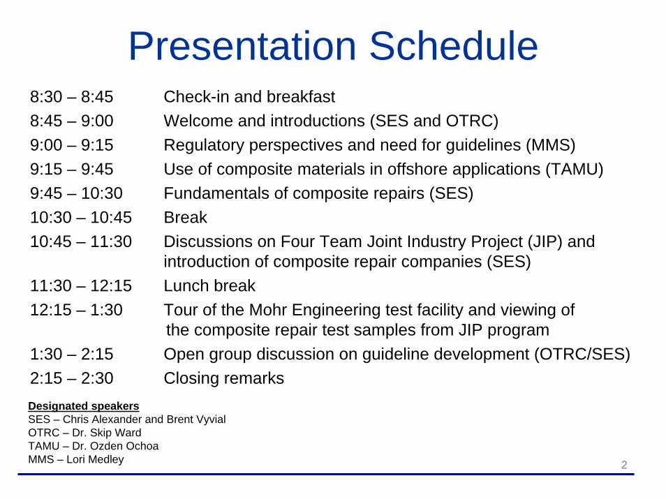
Presentation Schedule8:30 – 8:45 Check-in and breakfast8:45 – 9:00 Welcome and introductions (SES and OTRC)9:00 – 9:15 Regulatory perspectives and need for guidelines (MMS)9:15 – 9:45 Use of composite materials in offshore applications (TAMU)9:45 – 10:30 Fundamentals of composite repairs (SES)10:30 – 10:45 Break10:45 – 11:30 Discussions on Four Team Joint Industry Project (JIP) and
introduction of composite repair companies (SES)11:30 – 12:15 Lunch break12:15 – 1:30 Tour of the Mohr Engineering test facility and viewing of
the composite repair test samples from JIP program1:30 – 2:15 Open group discussion on guideline development (OTRC/SES)2:15 – 2:30 Closing remarksDesignated speakersSES – Chris Alexander and Brent VyvialOTRC – Dr. Skip WardTAMU – Dr. Ozden OchoaMMS – Lori Medley

3
Welcome and Introduction
• Introduction of guests• Facility information and layout• Today’s objectives
Fundamentals ofComposite Repairs
Presented byStress Engineering Services, Inc.
Chris [email protected]
5
Today’s Presentation• Background in pipeline evaluation and repairs• Examples of when composites can be used to
repair pipelines• Background on the major pipeline repair systems
using composite materials• U.S. government regulations• Guidelines for repair using composites and test
program elements• Repair of dents and gouges (mechanical
damage)• Question & Answer Session

6
Stress Engineering Services, Inc.• Emphasis on both testing and analysis of
pipeline systems• Have been involved in testing and analysis of
pipeline systems and products for 30 plus years• Significant work in pipeline testing and analysis
Full-scale testing of pipeline including burst pressure and cyclic pressure (fatigue) of dented pipesStudies associated with repair of mechanical damage via grinding relative to static and cyclic pressure loadsSES has evaluated/tested most of the major composite pipeline repair systems

7
Typical Aims of PipelineRepair Methods
• Restore strength to damaged pipes• Reduce strain in damaged areas of pipe• Seal corroded area of pipe from further development
of corrosion

8
Uses of Composite Materials(repair and structural reinforcement)
• Metal wall loss (due to corrosion)• Plain dents• Mechanical damage (dents with a gouge)• Re-rating pipeline system to achieve higher
operating pressures• Corrosion repair and replacement
Under insulation coating (UIC)Wear-resistant coatings (e.g. saddles)Underwater coatings
9
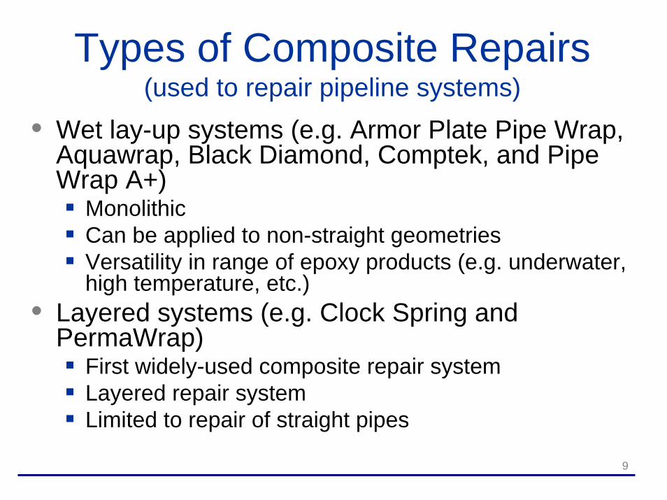
Types of Composite Repairs(used to repair pipeline systems)
• Wet lay-up systems (e.g. Armor Plate Pipe Wrap, Aquawrap, Black Diamond, Comptek, and Pipe Wrap A+)
MonolithicCan be applied to non-straight geometries Versatility in range of epoxy products (e.g. underwater, high temperature, etc.)
• Layered systems (e.g. Clock Spring and PermaWrap)
First widely-used composite repair systemLayered repair systemLimited to repair of straight pipes
10
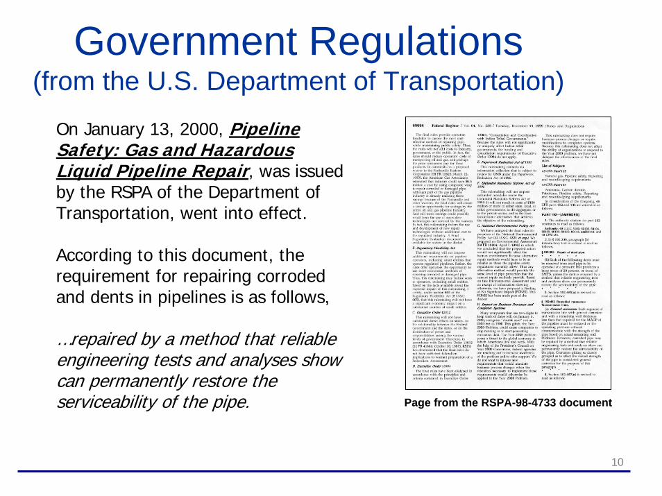
Government Regulations(from the U.S. Department of Transportation)
Page from the RSPA-98-4733 document
On January 13, 2000, Pipeline Safety: Gas and Hazardous Liquid Pipeline Repair, was issued by the RSPA of the Department of Transportation, went into effect.
According to this document, the requirement for repairing corroded and dents in pipelines is as follows,
…repaired by a method that reliable engineering tests and analyses show can permanently restore the serviceability of the pipe.

11
Guidelines for Evaluation of Composite Repair Methods
• Strength of the composite material• Environmental effects (e.g. cathodic
disbondment, temperature, acids and alkalines)• Effects of pressure (both static and cyclic)• Mechanics of load transfer from pipe to wrap• Long-term performance issues• Consistency in application and quality control in
manufacturing
The basic fundamental issues for evaluating composite repair methods are as follows:
12
Elements of a Typical Testing & Analysis Program
• Corrosion repair (burst testing)• Cyclic pressure effects on burst strength• Repair of mechanical damage (static and cyclic)• Load transfer analysis using strain gages and
Finite Element Analysis (FEA)• Tensile testing of composite materials• Adhesive lap shear testing• Effects of pressure at time of installation• Long-term testing

13
Specific Technical Items(discussed in today’s presentation)
• Corrosion Repair and load transfer• Repair of Pipe Fittings• Repair of Mechanical Damage (dents with
gouges)• Discussion on Installation Concepts
CORROSION REPAIR

15
Load Sequence of Composite Repairs during Pressurization
• Pipe and wrap stressed as internal pressure increased (load distribution dependant upon relative stiffness of two components)
• Once yielding in corroded region occurs, local stiffness of pipe reduced and load transferred to wrap
• Final burst pressure governed by ultimate strengths of pipe and composite materials
16
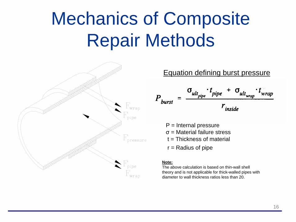
Mechanics of CompositeRepair Methods
Equation defining burst pressure
P = Internal pressureσ = Material failure stress t = Thickness of materialr = Radius of pipe
Note:The above calculation is based on thin-wall shell theory and is not applicable for thick-walled pipes with diameter to wall thickness ratios less than 20.
17
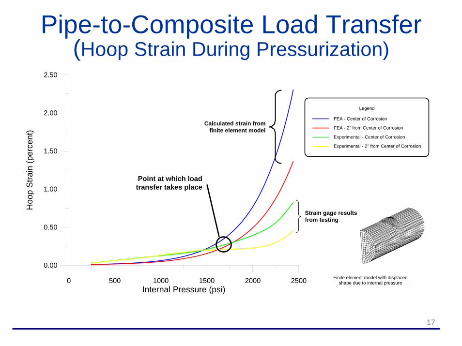
Pipe-to-Composite Load Transfer (Hoop Strain During Pressurization)
0 500 1000 1500 2000 2500Internal Pressure (psi)
0.00
0.50
1.00
1.50
2.00
2.50
Hoo
p St
rain
(per
cent
)
Legend
FEA - Center of Corrosion
FEA - 2" from Center of Corrosion
Experimental - Center of Corrosion
Experimental - 2" from Center of Corrosion
Note:1. Experimental strain values obtained using strain gages located beneath the APPW 360 wrap (2 bi-axial gages used)2. Two strain gages placed beneath the APPW 360 wrap - one positioned longitudinally in the center and the other 2" from the center of the corrosion along the axis of the pipe.3. Finite element analysis (FEA) results obtained using shell elements to model pipe, end caps, and 50% corrosion patch. Material model for FEA based upon non-linear elastic-plastic values using the yield and ultimate strength for the actual pipe.
Finite elementstrain results
(corrosionNOT repaired)
Experimental APPW 360strain results
Finite element model with displacedshape due to internal pressure
Point at which load transfer takes place
Strain gage resultsfrom testing
Calculated strain fromfinite element model
REPAIR OFPIPE FITTINGS
19
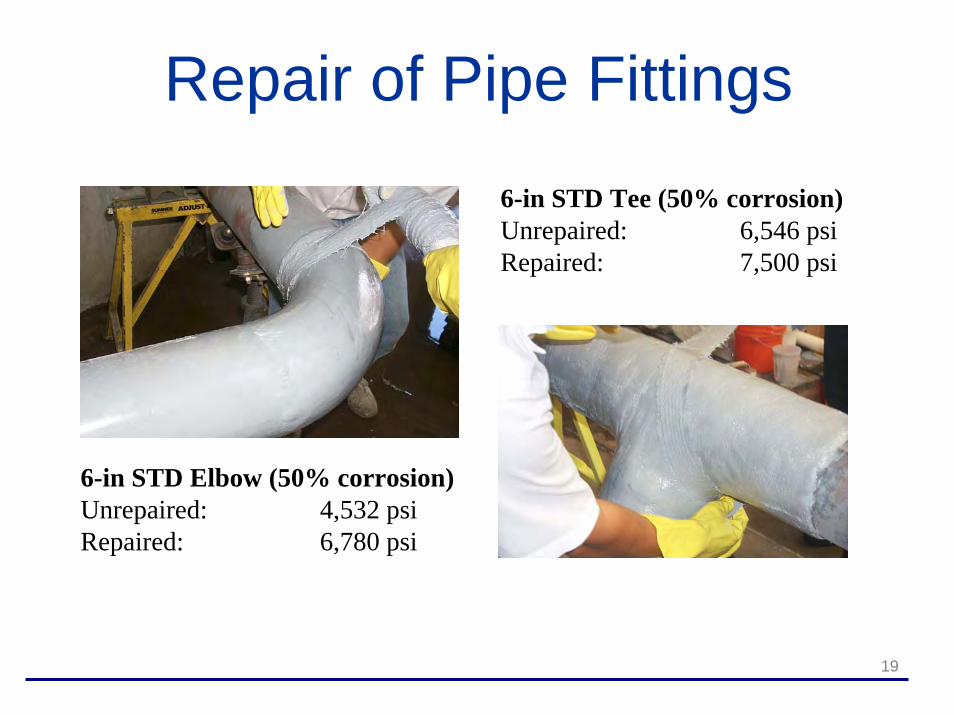
Repair of Pipe Fittings
6-in STD Elbow (50% corrosion)Unrepaired: 4,532 psiRepaired: 6,780 psi
6-in STD Tee (50% corrosion)Unrepaired: 6,546 psiRepaired: 7,500 psi

MECHANICAL DAMAGE

21
Defect Classification(and associated failure modes)
• Plain dents• Gouges (no denting present)• Mechanical damage (dents with
gouges)• Rock dents (constrained)• Failure modes/methods
Rupture versus leak before break (KIC, σ, a)Static burst versus fatigue failure (S-N relation)
22
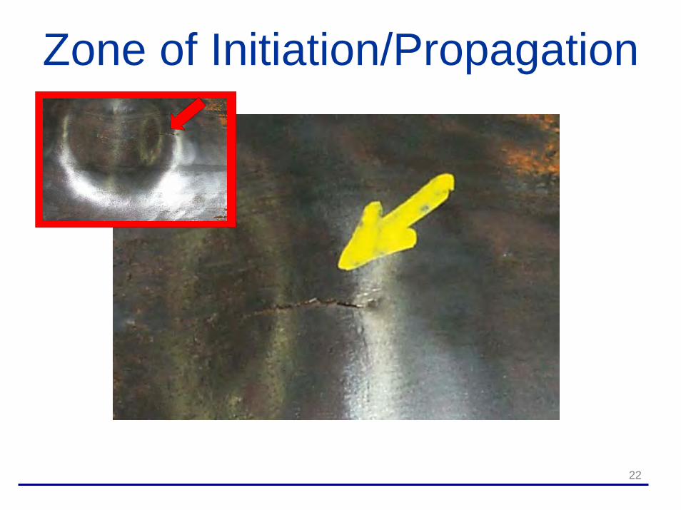
Zone of Initiation/Propagation
23
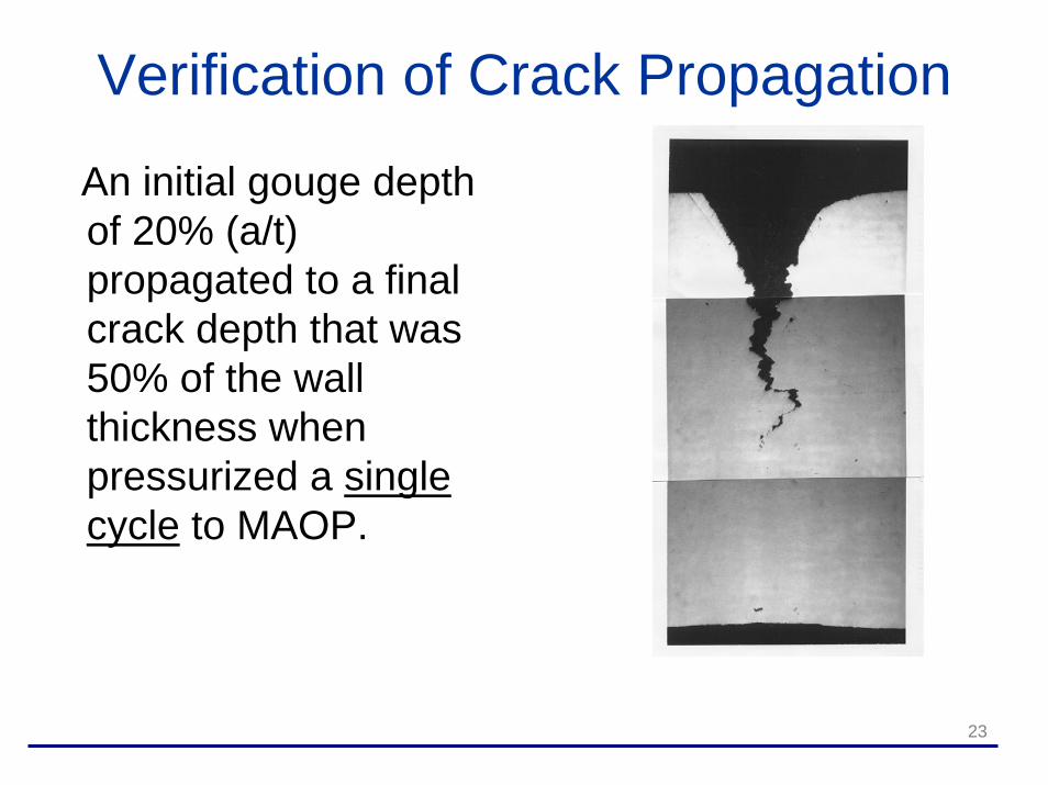
Verification of Crack Propagation
An initial gouge depth of 20% (a/t) propagated to a final crack depth that was 50% of the wall thickness when pressurized a single cycle to MAOP.
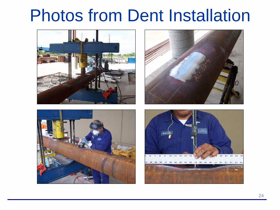
24
Photos from Dent Installation

25
Verification of Crack Propagation
The gouge in Sample P3C(from PRCI Research project) developed a crack that propagated from an initial gouge depth of 20% (a/t) to a final crack depth that was 50% of the wall thickness
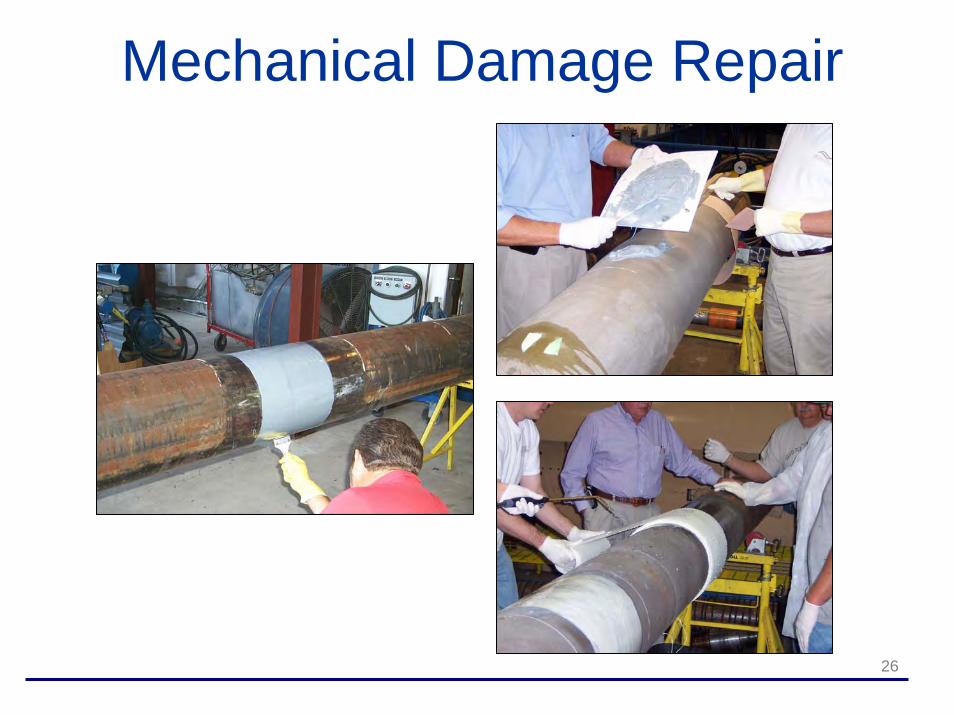
26
Mechanical Damage Repair
27
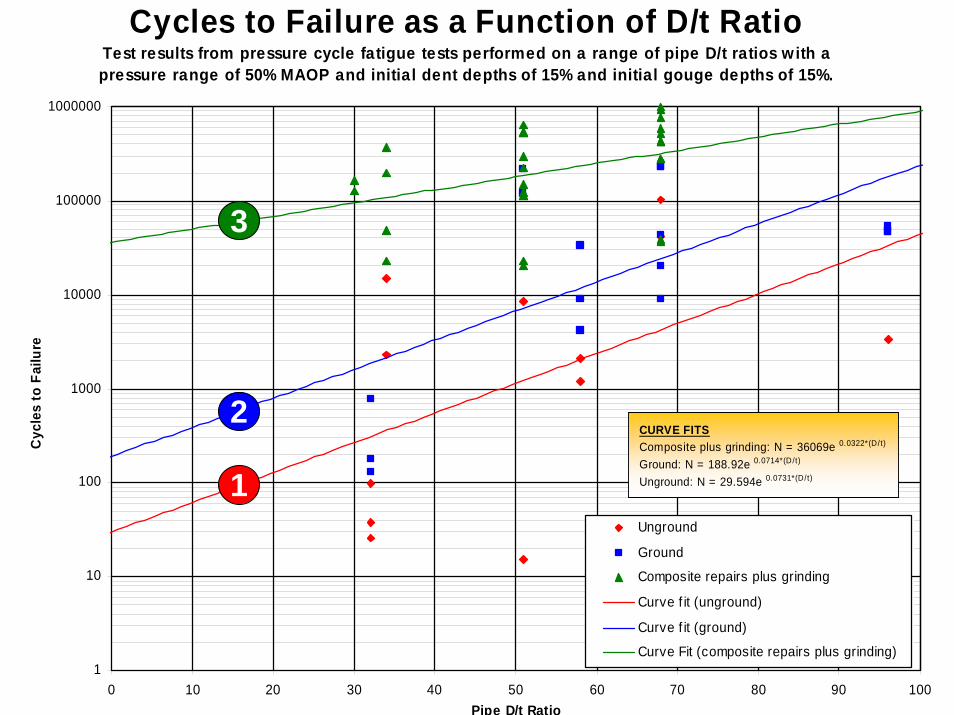
Mechanical Damage Fatigue Testing(Results for Armor Plate Pipe Wrap, Aquawrap, and Clock Spring similar)
Cycles to Failure as a Function of D/t RatioTest results from pressure cycle fatigue tests performed on a range of pipe D/t ratios with a pressure range of 50% MAOP and initial dent depths of 15% and initial gouge depths of 15%.
1
10
100
1000
10000
100000
1000000
0 10 20 30 40 50 60 70 80 90 100Pipe D/t Ratio
Cyc
les
to F
ailu
re
Unground
Ground
Composite repairs plus grinding
Curve f it (unground)
Curve f it (ground)
Curve Fit (composite repairs plus grinding)
CURVE FITSComposite plus grinding: N = 36069e 0.0322*(D/t)
Ground: N = 188.92e 0.0714*(D/t)
Unground: N = 29.594e 0.0731*(D/t)1
2
3
28
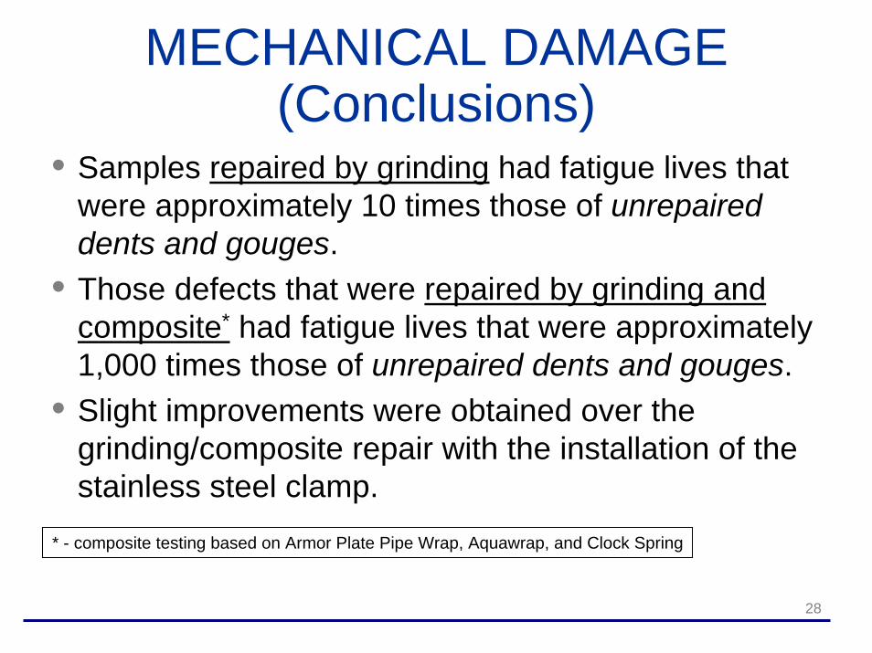
MECHANICAL DAMAGE (Conclusions)
• Samples repaired by grinding had fatigue lives that were approximately 10 times those of unrepaired dents and gouges.
• Those defects that were repaired by grinding and composite* had fatigue lives that were approximately 1,000 times those of unrepaired dents and gouges.
• Slight improvements were obtained over the grinding/composite repair with the installation of the stainless steel clamp.
* - composite testing based on Armor Plate Pipe Wrap, Aquawrap, and Clock Spring

INSTALLATIONAND
APPLICATION TECHNIQUES
30
Steps in Pipeline Repair• Locate damaged section(s)• Assess severity of damage (e.g. corrosion, mechanical
damage, etc.) and determine if repair is possible• Calculate required number of wraps (if appropriate for
respective repair type)• Clean and prepare pipe (surface preparation critical)• Install composite repair• Allow repair to cure per manufacturer’s
recommendations• Restore pipeline environment (e.g. backfill and re-
pressurize)

31
Observations on Current Composite Repair Methods
• For more than 10 years, the pipeline industry has been making repairs using composite materials
• A significant body of research exists addressing a variety of repair types
• It is the presenter’s observation that the missing link with the composite repair systems is long-term test data (especially in terms of the adhesive/resin systems)
• New standards such as ASME’s PCC-2 will set minimum design criteria, although the focus up to this point has been repair of onshore pipelines

Four TeamJoint Industry Project
Presented byStress Engineering Services, Inc.
Brent [email protected]
Chris [email protected]
33
Overview of Presentation• Current design needs for offshore riser
repairs• Joint Industry Project (JIP) test program
Elements of test programPresentation of resultsGeneral observations
• Future developmentsAdditional analysis and testing workCompleting the guideline development for MMSAddressing long-term performance issues

34
Current Design Needs (Repair System Development)
• Integrating riser loads• Expected results for the different load
requirementsInternal pressureAxial tensionBending
• Essential elements relative to design repair requirements
• Consider riser loads subject to appropriate design stress (or strain) limits
• Addressing and qualifying potential upset conditions
35
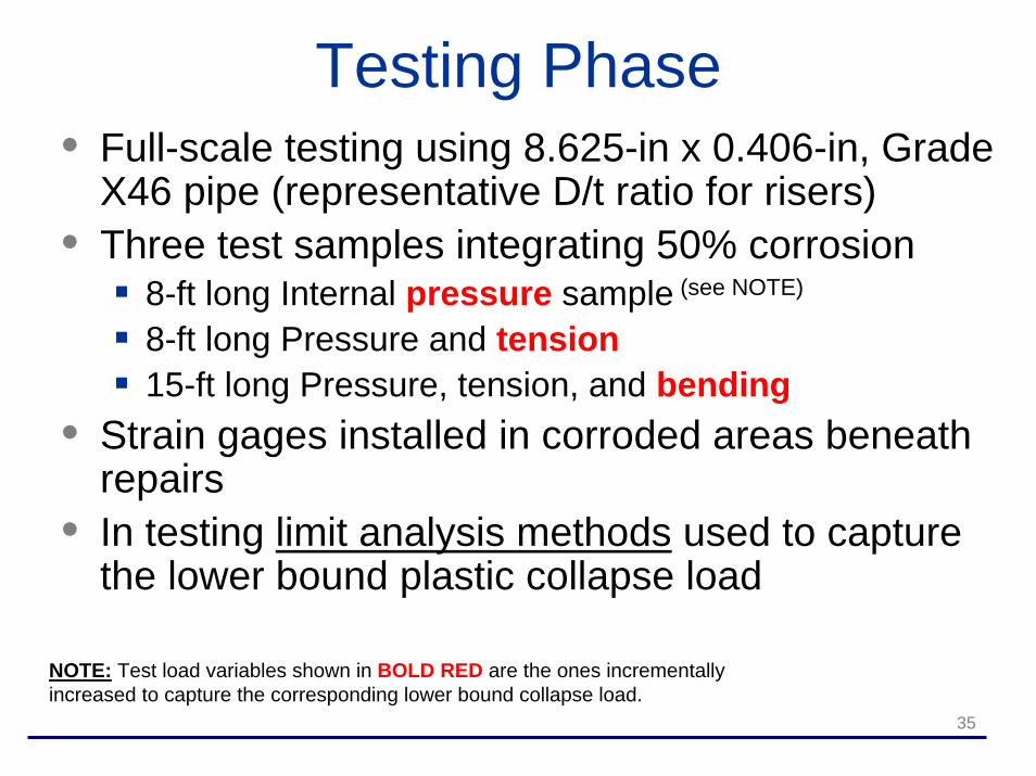
Testing Phase• Full-scale testing using 8.625-in x 0.406-in, Grade
X46 pipe (representative D/t ratio for risers)• Three test samples integrating 50% corrosion
8-ft long Internal pressure sample (see NOTE)
8-ft long Pressure and tension15-ft long Pressure, tension, and bending
• Strain gages installed in corroded areas beneath repairs
• In testing limit analysis methods used to capture the lower bound plastic collapse load
NOTE: Test load variables shown in BOLD RED are the ones incrementally increased to capture the corresponding lower bound collapse load.

36
Testing Details(Sample loading and defect configuration)
Tensile Force(both ends)
d1 d2 d3 d4 d5
110 inches
55 inches
180 inches (15 feet)
(Four-point bending force locations)
Selected displacement measurement locations
0.200 inches deep24-inches
30° taperBreak corners
Simulated corrosion on outside surface of pipe (circumferential groove)
37
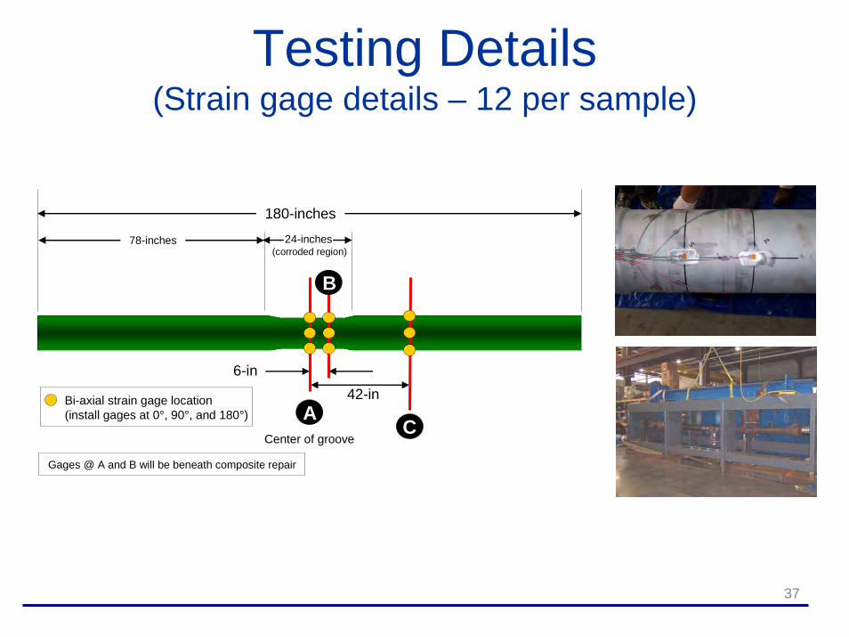
Testing Details(Strain gage details – 12 per sample)
180-inches
78-inches
6-in42-inBi-axial strain gage location
(install gages at 0°, 90°, and 180°) A
B
C
Gages @ A and B will be beneath composite repair
Center of groove
24-inches(corroded region)

38
Four Repair Systems• Product A
E-glass with water-activated urethane matrix• Product B (test data not included)
E-glass with water activated urethane matrix• Product C
Carbon with epoxy matrix• Product D
E-glass with epoxy matrix

39
Test Results(Burst pressure sample)
Hoop Strain versus Applied Internal PressureStrain gage readings on pipe beneath repair
0
1000
2000
3000
4000
5000
6000
7000
8000
9000
10000
0 2000 4000 6000 8000 10000 12000M iscrostrain (10,000 ms = 1 percent strain)
Inte
rnal
Pre
ssur
e (p
si)
Unrepaired Sample New Pipe (no corrosion) Product A
Product B Product C Product D
40
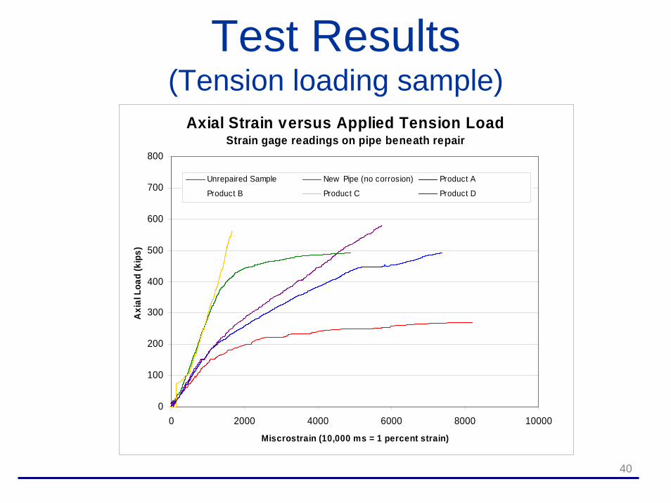
Test Results(Tension loading sample)
Axial Strain versus Applied Tension LoadStrain gage readings on pipe beneath repair
0
100
200
300
400
500
600
700
800
0 2000 4000 6000 8000 10000
Miscrostrain (10,000 ms = 1 percent strain)
Axi
al L
oad
(kip
s)
Unrepaired Sample New Pipe (no corrosion) Product A
Product B Product C Product D
41
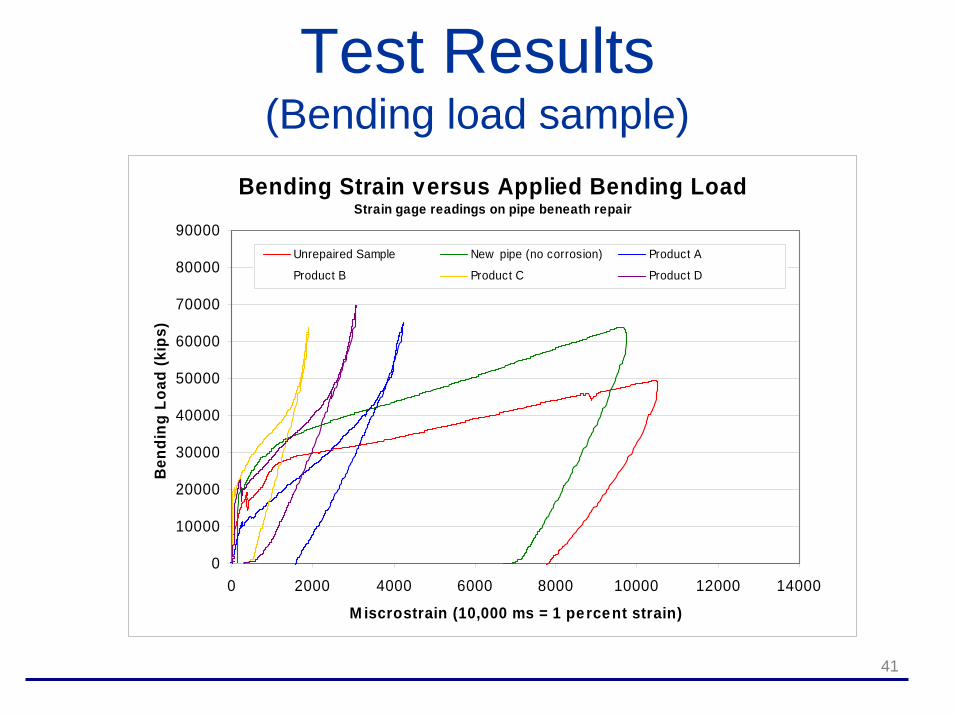
Test Results(Bending load sample)
Bending Strain versus Applied Bending LoadStrain gage readings on pipe beneath repair
0
10000
20000
30000
40000
50000
60000
70000
80000
90000
0 2000 4000 6000 8000 10000 12000 14000
M iscrostrain (10,000 ms = 1 percent strain)
Ben
ding
Loa
d (k
ips)
Unrepaired Sample New pipe (no corrosion) Product A
Product B Product C Product D

42
General Comments on Testing• This program integrated typical riser loads and
was able to capture strain levels in pipe during testing
• Success criteria is rooted in the ability of the repair to reinforce the corroded region (i.e. reduce strain in the reinforced steel)
• Final consideration of success should considerQuality control and consistency in applicationEconomics including efficiency of the repair processLong-term performance

43
Analysis Phase• Simulation of repair considering loads
considered during testing phase• Finite element analysis employing specific
composite properties and elastic-plastic material properties for steel riser pipes
• Limit analysis methods used to capture the lower bound plastic collapse load and corresponding design load condition
44
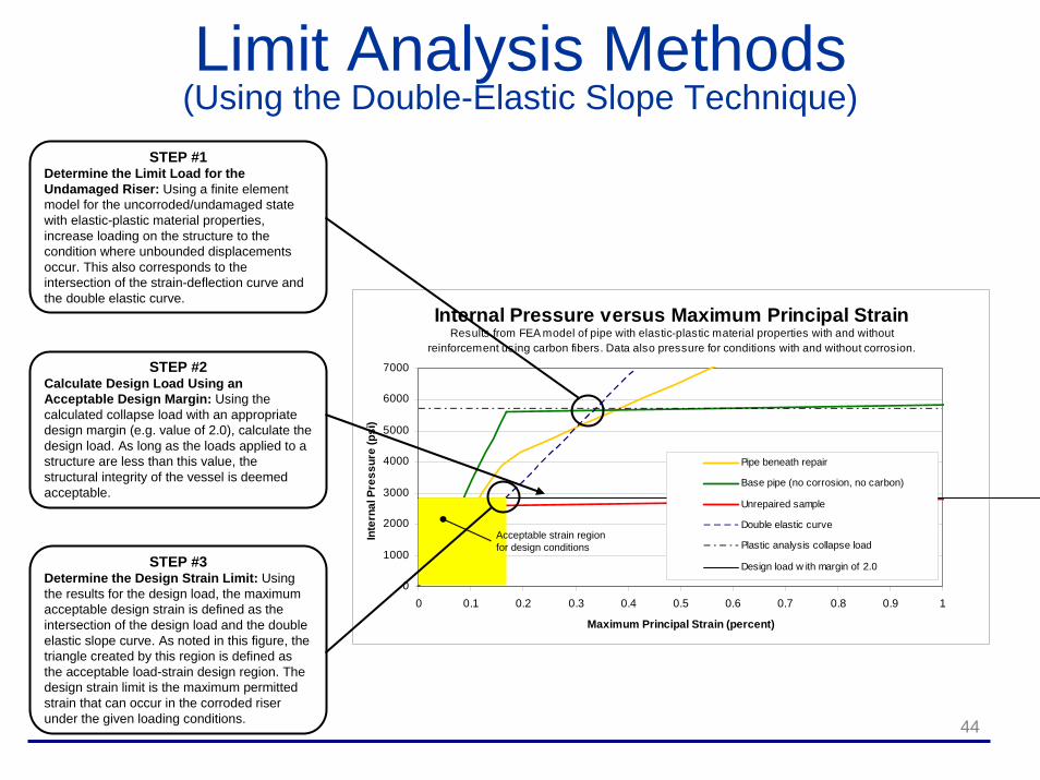
Limit Analysis Methods(Using the Double-Elastic Slope Technique)
STEP #1Determine the Limit Load for the Undamaged Riser: Using a finite element model for the uncorroded/undamaged state with elastic-plastic material properties, increase loading on the structure to the condition where unbounded displacements occur. This also corresponds to the intersection of the strain-deflection curve and the double elastic curve.
Internal Pressure versus Maximum Principal StrainResults from FEA model of pipe with elastic-plastic material properties with and without
reinforcement using carbon fibers. Data also pressure for conditions with and without corrosion.
0
1000
2000
3000
4000
5000
6000
7000
0 0.1 0.2 0.3 0.4 0.5 0.6 0.7 0.8 0.9 1
Maximum Principal Strain (percent)
Inte
rnal
Pre
ssur
e (p
si)
Pipe beneath repair
Base pipe (no corrosion, no carbon)
Unrepaired sample
Double elastic curve
Plastic analysis collapse load
Design load w ith margin of 2.0
Acceptable strain regionfor design conditions
STEP #2Calculate Design Load Using an Acceptable Design Margin: Using the calculated collapse load with an appropriate design margin (e.g. value of 2.0), calculate the design load. As long as the loads applied to a structure are less than this value, the structural integrity of the vessel is deemed acceptable.
STEP #3Determine the Design Strain Limit: Using the results for the design load, the maximum acceptable design strain is defined as the intersection of the design load and the double elastic slope curve. As noted in this figure, the triangle created by this region is defined as the acceptable load-strain design region. The design strain limit is the maximum permitted strain that can occur in the corroded riser under the given loading conditions.
45
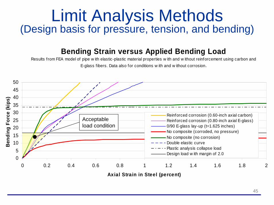
Limit Analysis Methods(Design basis for pressure, tension, and bending)
Bending Strain versus Applied Bending LoadResults f rom FEA model of pipe w ith elastic-plastic material properties w ith and w ithout reinforcement using carbon and
E-glass f ibers. Data also for conditions w ith and w ithout corrosion.
05
101520253035404550
0 0.2 0.4 0.6 0.8 1 1.2 1.4 1.6 1.8 2
Axial Strain in Steel (percent)
Bend
ing
Forc
e (k
ips)
Reinforced corrosion (0.60-inch axial carbon)Reinforced corrosion (0.80-inch axial E-glass)0/90 E-glass lay-up (t=1.625 inches)No composite (corroded, no pressure)No composite (no corrosion)Double elastic curvePlastic analysis collapse loadDesign load w ith margin of 2.0
Acceptableload condition
46
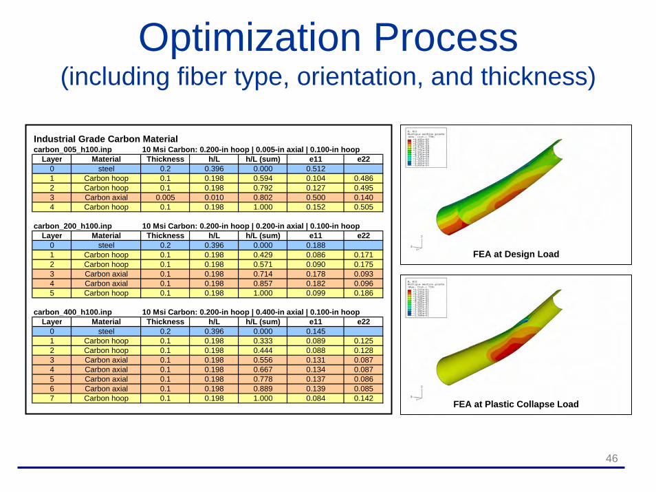
Optimization Process(including fiber type, orientation, and thickness)
Industrial Grade Carbon Materialcarbon_005_h100.inp 10 Msi Carbon: 0.200-in hoop | 0.005-in axial | 0.100-in hoop
Layer Material Thickness h/L h/L (sum) e11 e220 steel 0.2 0.396 0.000 0.5121 Carbon hoop 0.1 0.198 0.594 0.104 0.4862 Carbon hoop 0.1 0.198 0.792 0.127 0.4953 Carbon axial 0.005 0.010 0.802 0.500 0.1404 Carbon hoop 0.1 0.198 1.000 0.152 0.505
carbon_200_h100.inp 10 Msi Carbon: 0.200-in hoop | 0.200-in axial | 0.100-in hoopLayer Material Thickness h/L h/L (sum) e11 e22
0 steel 0.2 0.396 0.000 0.1881 Carbon hoop 0.1 0.198 0.429 0.086 0.1712 Carbon hoop 0.1 0.198 0.571 0.090 0.1753 Carbon axial 0.1 0.198 0.714 0.178 0.0934 Carbon axial 0.1 0.198 0.857 0.182 0.0965 Carbon hoop 0.1 0.198 1.000 0.099 0.186
carbon_400_h100.inp 10 Msi Carbon: 0.200-in hoop | 0.400-in axial | 0.100-in hoopLayer Material Thickness h/L h/L (sum) e11 e22
0 steel 0.2 0.396 0.000 0.1451 Carbon hoop 0.1 0.198 0.333 0.089 0.1252 Carbon hoop 0.1 0.198 0.444 0.088 0.1283 Carbon axial 0.1 0.198 0.556 0.131 0.0874 Carbon axial 0.1 0.198 0.667 0.134 0.0875 Carbon axial 0.1 0.198 0.778 0.137 0.0866 Carbon axial 0.1 0.198 0.889 0.139 0.0857 Carbon hoop 0.1 0.198 1.000 0.084 0.142
FEA at Design Load
FEA at Plastic Collapse Load

47
Future Developments• Developing a summary report that captures the
results of the JIP test program• Preparation of Composite Repair Guidelines for
MMS that includes:Observations from JIP studyDevelopment of strain-based design criteria for steelLimitations on composite design stresses in the absence of long-term stress rupture data (e.g. 40% UTS)
• A follow-on study is needed to establish repair criteria for offshore repair and should include a study of long-term performance
48
Overall Comments(from Stress Engineering Services, Inc .)
• Today’s workshop is the culmination of more than 10 years worth of research on composite materials used to repair pipelines
• Composite materials are currently being used offshore in the Gulf of Mexico and other regions around the world
• To be effective, composite repair systems must be designed to ensure (as a minimum):
Adequate reinforcement for the repaired steelLong-term strength exists in the composite materials


