
COMPARISON OF DIFFERENT GUIDELINES FOR
ACCESSIBILITY OF BUILT ENVIRONMENT IN INDIA
A Brief Analysis and Recommendations
By
Diversity and Equal Opportunity Centre (DEOC)
For
National Centre for Promotion of Employment for Disabled People (NCPEDP)
Supported by
Mphasis Limited
May 2016

2
Table of Contents
1 INTRODUCTION ................................................................................................................................................................................................................................................................... 4
1.1 METHODOLOGY .................................................................................................................................................................................................................................................................................................... 4 1.2 TERMINOLOGY ...................................................................................................................................................................................................................................................................................................... 5
2 ANTHROPOMETRICS .......................................................................................................................................................................................................................................................... 6
2.1 MANUAL WHEELCHAIR....................................................................................................................................................................................................................................................................................... 6 2.2 ELECTRIC WHEELCHAIR ..................................................................................................................................................................................................................................................................................... 7 2.3 REACH .................................................................................................................................................................................................................................................................................................................... 8 2.4 TURNING SPACE ................................................................................................................................................................................................................................................................................................ 10 2.5 VISION ZONE ...................................................................................................................................................................................................................................................................................................... 11 2.6 PROTRUDING OBJECTS/SOLITARY OBSTACLES (WITH RESPECT TO WHITE CANE) ............................................................................................................................................................................... 11 2.7 TACTILE WALKING SURFACE INDICATORS (TWSIS) ................................................................................................................................................................................................................................... 13
3 WALKS AND PATHS ......................................................................................................................................................................................................................................................... 15
4 PARKING.............................................................................................................................................................................................................................................................................. 22
5 RAMPS .................................................................................................................................................................................................................................................................................. 28
6 KERB RAMPS ...................................................................................................................................................................................................................................................................... 35
7 HANDRAILS ........................................................................................................................................................................................................................................................................ 38
8 STAIRCASE .......................................................................................................................................................................................................................................................................... 44
9 DOORS .................................................................................................................................................................................................................................................................................. 53
10 ELEVATORS AND LIFTS .................................................................................................................................................................................................................................................. 64
11 VERTICAL AND INCLINED LIFTING PLATFORMS .................................................................................................................................................................................................. 80
12 UNISEX ACCESSIBLE TOILETS ...................................................................................................................................................................................................................................... 83
13 WASHBASIN ....................................................................................................................................................................................................................................................................... 97

3
14 TAPS .................................................................................................................................................................................................................................................................................... 100
15 URINALS ............................................................................................................................................................................................................................................................................ 102
16 WC COMPARTMENTS FOR AMBULANT DISABLED PEOPLE ............................................................................................................................................................................ 104
17 BATHROOMS AND SHOWERS .................................................................................................................................................................................................................................... 105
18 EMERGENCY EVACUATION NEEDS ........................................................................................................................................................................................................................... 111
19 SIGNAGE ............................................................................................................................................................................................................................................................................ 121
20 CONCLUSION .................................................................................................................................................................................................................................................................... 134
4
1 Introduction There are three documents detailing the norms for the accessibility of built environments (as on March 2016) in India. They
are:
1. Handbook on Barrier Free and Accessibility, Central Public Works Department (CPWD), 2014 (referred to as CPWD in this document).
2. Harmonised Guidelines and Space Standards for Barrier Free Built Environment for Persons with Disability and Elderly Persons, Ministry of Urban Development, 2015 (referred to as HG in this document).
3. Annexure B, Anthropometrics and Specific Requirements for Barrier Free Buildings and Built Environment, Part 3 Development Control Rules and General Building Requirements, Draft National Building Code of India, Bureau of
Indian Standard (BIS), 2015 (referred to as NBC in this document).
There is also an international Standard: ISO 21542:2011, Building construction - Accessibility and Usability of the Built
Environment, International Organization for Standardization (referred to as ISO in this document).
It was felt that an exercise should be undertaken to compare the Guidelines and to highlight the differences so that they could be ironed out and so that there is only one Standard for India with regard to the accessibility of built environments.
Keeping the above in view, NCPEDP, an advocacy organisation working for the rights of persons with disabilities, commissioned this work to DEOC (www.deoc.in), a social enterprise, specialising in the field of policy research and training.
This comparative analysis is intended to aid government/policy makers/experts when finalising the Standards for India.
1.1 Methodology
DEOC studied the various sections of the three Indian Guidelines. There were inconsistencies with regard to the areas covered in each of the Guidelines. For example, the Harmonised Guidelines have included bus stops, railway stations, taxi
and auto rickshaw stands, airports, adapted housing, etc. while the other two Guidelines, CPWD and NBC, have not covered them. It was also seen that certain areas like auditoriums, sports arenas, swimming pools, management and maintenance

5
issues, etc. have not been included in any of the Guidelines. So it was decided that the areas which are covered in at least two out of the three Indian Guidelines should be included in the study, so that comparison is possible.
The Guidelines, including the ISO Standards, were systematically compiled in a table format in order to enable easy comparison. A brief analysis was also undertaken to highlight the differences. At many places, the text had to be edited to
make it more readable, but this was not possible at all places. Observations and recommendations have been listed under each section.
1.2 Terminology
As can be seen from the titles of the three documents, different terms are being used to refer to the set of accessibility
requirements. The CPWD refers to it as a ‘Handbook’ while the Ministry of Urban Development refers to it as ‘Guidelines’; for the BIS, it is a ‘Building Code’, and for the ISO, it is a ‘Standard’. Unfortunately these terms have different meanings. For example ‘Guidelines’ are not considered mandatory but ‘Standards’ are considered mandatory. However please note that,
in this document, the terms Guidelines and Standards are interchangeably used.

6
2 Anthropometrics
2.1 Manual Wheelchair
Dimensions CPWD HG NBC
Length 645 mm- 1100 mm
1000-1200 mm 100 mm - 1200 mm
Width
510 mm - 725
mm
650 – 720 mm
650 - 720 mm
Height 850 mm - 1140 mm
910 - 950 mm 910 - 950 mm
Wheelchair footrest - 350 mm (deep) 350 mm (deep)
Wheelchair castor width - 12 mm 12 mm
Seat height - 480 mm 480 mm
Armrest height - 760 mm 760 mm
Lap height - 675 mm 675 mm
When the wheelchair is
folded -
width : 300 mm height of armrest :
760 mm
width : 300 mm height of armrest :
760 mm
Weight 10.27 kg - -

7
Observations and Recommendations
1. HG and NBC dimensions of manual wheelchair are the same. They are more comprehensive than the CPWD
Guidelines. The source from where the information has been taken has not been given. It is recommended that CPWD should take the dimensions given in HG and NBC, which seem more realistic. It would be useful if HG and NBC mention the source of information i.e. from where the anthropometrics of manual wheelchair have been taken.
2. There is a typographical error in NBC regarding the length of the wheelchair. Instead of 1000 mm it is mentioned as 100 mm as can be seen in the Table above. It should be corrected.
3. The ISO 21542:2011 does not have the dimensions of the wheelchair. It is based on ISO 7176-5 and ISO/TR 13570-21 which details the dimensions and maneuvering space of wheelchairs.
2.2 Electric Wheelchair
Dimensions CPWD
Length 1060 - 1200 mm
Width 520 - 700 mm
Height 1010 - 1400 mm
Weight 36.100 kg
Observations and Recommendations
1. Only CPWD Guidelines have given the dimensions of electric wheelchair. The source from where the information has been taken has not been given. It is recommended that HG and NBC add the information.

8
2.3 Reach
Reach CPWD HG NBC ISO
Forward reach of a wheelchair user (without obstruction)
Maximum reach from
the Floor (upper)
1200 mm 1200 mm 1200 mm 1100 mm
Maximum reach from the floor (Lower)
400 mm 380 mm 400 mm 400 mm
Forward reach (with obstruction)
Maximum reach from the floor (upper)
1100 mm 1000 mm 1000 mm -
Depth 500 mm 500 mm - -
Side reach (without obstruction)
Maximum reach from
the floor (upper)
1300 mm 1300 mm 1300 mm -
Maximum reach from the floor (Lower)
250 mm 250 mm 250 mm 250 mm
Side reach (with
obstruction)
The maximum side reach
over an obstruction 860 mm high by 500 mm deep is 1200 mm from
the floor
The maximum 860 mm high x 500
mm deep is 1200 mm. Side reach over obstruction (upper) – 1200 mm from floor level. Max. Side reach over
obstruction (lower) – 500 mm
The maximum side
reach over an obstruction of size 860 mm high x 500
mm deep is 1200 mm from the floor
-

9
Reach CPWD HG NBC ISO
Comfortable and
maximum reach zone (when seated on a wheelchair)
- Comfortable : 900 mm - 1200 mm;
Maximum 1200 mm - 1400 mm.
Comfortable : 900
mm - 1200 mm. ; Maximum 1200 mm - 1400 mm.
-
Observations and Recommendations
1. Maximum Forward Reach from the Floor (upper) without obstruction: The ISO Standard is 1100 mm while Indian Standards are saying 1200 mm. Indian Standards should adopt the ISO Standard of 1100 mm, which seems more
suitable for larger population. 2. Maximum Forward Reach from the Floor (lower) without obstruction: The HG Standard is different (380 mm) from the
rest (400 mm). HG should change it to 400 mm as per the ISO.
3. Maximum Reach from the Floor (upper) with obstruction: The CPWD Standard is different (1100 mm) from the rest (1000 mm). CPWD should change it to 1000 mm. NBC has not given the ‘depth’ of the obstruction, which should be
added as given in other Standards. 4. Maximum side reach with obstruction (lower): HG says 500 mm. It is not there in other Standards. It should be added
in CPWD and NBC.

10
2.4 Turning Space
Wheelchair CPWD HG NBC ISO
Manual wheelchair
Minimum: 1500 mm
1/4 Turn : 1500 mm X 1500 mm
1/2 Turn: 1500 mm X 1700
mm
Minimum: 1500 mm.
Ideal: 2000 mm
Minimum: 1500 mm Comfortable: 1800 mm
Ideal: 2000 mm
Dimensions are given for different situations, like landings, in front of the door, etc. for 45
degrees, 180 degrees etc. Value ranges from 1500 to 2000 mm.
Powered wheelchairs/
scooters
1800 mm - -
Observations and Recommendations
1. The dimensions given are more or less similar in all the Guidelines. The minimum is based on the dimensions of manual wheelchairs in HG and NBC.
2. The turning space requirement varies depending on the degree of the turning required 45 degrees, 90 degrees, 180
degrees etc. This should be clearly explained in the HG and NBC Guidelines and should comply with the ISO Standards.
3. The terminology used by CPWD should change to degree rather the ¼ turn etc. It should also be made more comprehensive based on the ISO Standards.

11
2.5 Vision Zone
Dimensions CPWD HG NBC ISO
Placement height of information panels along pathways and maps
- Between 900 mm and 1800 mm
Between 900 mm and 1800 mm
Between 1200 mm and 1600 mm
Size of the smallest letter
15 mm 15 mm -
Observations and Recommendations
1. Standards given in HG and NBC are the same. CPWD has not included any specification on vision zone. 2. As per ISO, information, including directional and functional signs should be placed below 1600 mm, where it is easy
to approach, to touch and read the sign. The upper limit given in HG and NBC should be lowered to 1600 mm as per
the ISO Standard, as it would suit larger population.
2.6 Protruding Objects/Solitary Obstacles (with respect to white cane)
Dimensions CPWD HG NBC ISO
Hazard zone
Between 680 mm and 2000
mm (projecting
beyond 90 mm)
Between 300 mm and 2200 mm (projecting beyond 100 mm)
Headroom not mentioned
in text but the diagram says 2200 mm.
Between 300 mm and 2100 mm (projecting beyond 100 mm)
Headroom minimum –
2100 mm
Between 300 mm and 2100 mm (projecting more than 100 mm)
Headroom minimum – 2100
mm

12
Dimensions CPWD HG NBC ISO
Hazard protection
Hazard protection should be provided if objects
project more than 100 mm into an access route
and their lower edge is more than 300 mm above the ground. Hazard
protection associated with such objects should take
the form of a kerb or other solid barrier so that person with visual
impairment can detect the hazard using a cane. The
hazard protection should not extend beyond the front edge of the object,
nor should it be set back more than 100 mm from
its front edge.
Hazard protection shall be provided if objects project
more than 100 mm into an access route and their
lower edge is more than 300 mm above the ground. Hazard
protection associated with such objects shall take
the form of a kerb or other solid barrier so that a blind or partially sighted
person can detect the hazard using a cane. The
hazard protection shall not extend beyond the front edge of the object,
nor shall it be set back more than 100 mm from
its front edge. In case the hazard is at 600 mm above the ground, the
same will not be in the range of detection of the
mobility aid/white cane and should therefore be extended to the ground
When a projecting obstacle exists, a protective guard shall be
provided at ground level, under the projecting object such as a
kerb or fixed element at a height of 100 mm – 300 mm as cane detection. Cane detection shall not
be set back more than 100 mm from the face of the projecting
object. Wing walls, side partitions, alcoves or recesses are solutions for projecting elements where free
space under the object is needed. Winged protection shall extend
continuously between 300 mm and 1 000 mm above the floor and shall contrast visually with the
background.

13
Dimensions CPWD HG NBC ISO
level.
Observations and Recommendations
1. The hazard zone is different in HG, NBC and CPWD, while it’s the same in NBC and ISO. It is recommended that all
Indian Standards follow the guidelines as recommended in NBC.
2. The minimum headroom is specified in NBC and ISO. This needs to be incorporated in CPWD and HG.
3. Hazard protection is not described in CPWD. It is recommended that all Indian Standards be aligned to NBC and NBC
should include the description on winged protection in this section as in ISO.
2.7 Tactile Walking Surface Indicators (TWSIs)
Dimensions CPWD HG NBC ISO
Types of
Tiles
Directional Tile/Block:
Parallel raised bars for guiding the users along an intended
safe path. Hazard Warning
Tile/Block: Raised big dots (35mm in diameter) arranged in
square grid parallel to the sides of the slab
Tactile Guiding
Blocks (Line-type): This block
indicates a correct path/route to
follow for a person with visual impairment
Tactile Warning Blocks (Dot-type):
Tactile Guiding Blocks – Tiles of
size 300 mm x 300 mm that incorporate flat topped bars 5 mm (±0.5mm) high, 20 mm wide and
spaced 50 mm from the centre of one bar to the centre of the next.
They are used externally to guide people with visual impairments along the circulation path.
Tactile Warning Blocks – Tiles of size 300 mm x 300 mm that
Attention indicators and guiding
indicators. Tactile attention indicators may be installed at the vicinity of pedestrian crosswalks,
the platforms of railway stations, and both the top and bottom of
stairs and ramps, and in front of escalators, travelators and elevators, and the like to ensure
safety. Tactile guiding indicators may be

14
Dimensions CPWD HG NBC ISO
for indication of
potential hazards ahead. Positional Tile/Block:
Raised small dots (23 mm in diameter)
placed in staggered positions for indication of possible
change in walking directions.
This block
indicates an approaching potential hazard
or a change in direction of the
Walkway. Figure 5-1 has
dimensions for warning blocks
and figure 5-3 has dimensions for guiding blocks.
incorporate rows of 5 mm
(±0.5mm) high flat topped blister like domes that are easily detectable underfoot by persons
with visual impairments, recognized as a sign of
approaching hazards. Figure 30 gives the diameters etc
of the warning blocks.
used in combination with
attention indicators in order to indicate the walking route where no other tactual information is
available to get from one place to another. Annexure A is very
detailed and includes dimensions of domes and bars, visual contrast, spacings etc. etc.
Observations and Recommendations
1. CPWD mentions three types of tiles whereas HG, NBC and ISO mention two types. CPWD should make it to two types based on ISO.
2. Some specifications like dimensions of bars and cones are only given in the figure and not in text in HG and NBC. All information should also be in text.
3. Terminology to refer the tactile blocks is different in different Guidelines. The term ‘Tactile Walking Surface Indicators (TWSIs)’ is used in ISO whereas the term, ‘Tactile Ground Surface Indicators (TGSI)’ is used in NBC and HG. CPWD uses terms tactile tile or blocks. There should be one terminology that should be used. ISO
terminology can be adopted. The Annexure A, ‘Tactile walking surface indicators (TWSIs)’ of ISO is detailed and could be adopted by the Indian Standards.

15
3 Walks and Paths
Dimensions CPWD HG NBC ISO
Minimum clear
width
For one way
traffic: 1200 mm For two way
traffic : 1650 mm -1800
mm
For two way traffic: 1800
mm. Exceptional cases (such as around trees/poles etc.):
1500 mm.
For two way traffic: 1800 mm.
Exceptional cases (such as around trees/poles etc): 1500 mm.
For constant two way
traffic: 1800 mm For frequent two-way traffic, 1500 mm, provided that
passing places are included at intervals of maximum 25 m;
Infrequent two-way traffic : 1200 mm, a passing and turning space of at least 1800
mm x 2000 mm should be provided for every 25 m;
When it is unlikely that people will have to pass one another: 900 mm, a turning
space of at least 1800 mm x 2000 mm should be provided
for every 25 m.
Free from barriers
Free from protrusion
hazards, steps, kerbs other than
dropped kerbs,
steep ramps, doors or
Avoid gratings and manholes in walks.
Gratings and manholes shall be avoided in walks.
Obstacles, such as objects or signs mounted on walls, bollards, columns or
freestanding supports along the walking
path shall be avoided.
Obstacles, such as objects or signs mounted on walls,
bollards, columns or free-standing supports along the walking path should be
avoided.

16
Dimensions CPWD HG NBC ISO
doorways
which will impede the passage of a
wheelchair.
Solitary obstacles
projecting into an access
route
Obstacles such as lighting columns, bollards, signposts,
seats and trees, should be located at or beyond the
boundaries of walkways. Where unavoidable, protruding objects should not
reduce the clear width of an accessible route or
maneuvering space. Bollards should be avoided
but where necessary be at least 1000 mm high, provide
a wheelchair passage width of at least 900 mm (Figure 5-5), and should not be linked
with chains.
Obstacles, such as objects or signs mounted on walls,
bollards, columns or freestanding supports along
the walking path shall be avoided. Unavoidable free standing posts or columns
within access routes on pathways shall be clearly
marked with visual indicators. Bollards shall be avoided, but
where necessary shall be at least 1 000 mm high and shall
provide a wheelchair passage width of at least 900 mm, and should not be linked with
chains.
Objects with a height lower than 1 000 mm can create a
hazard for blind or partially sighted people. Permanent
equipment that cannot be located outside the boundaries of a path shall be:
a)designed to be easily seen with a minimum difference in
LRVs of 30 points to the background, and b) shielded to protect against
impact, and c)accompanied by a feature
that warns of the presence of a potential hazard and is detectable for a person using
a white cane or stick.
Visual
indicators for unavoidable
free standing
A band of 200 mm, between
heights of 1400 mm and 1600 mm from the walkway
floor finish, and which
Visual indicators at least 75
mm in height with a minimum visual contrast of 30
points difference to the
Visual indicators at least 75
mm in height with a minimum visual contrast of 30 points
difference to the background

17
Dimensions CPWD HG NBC ISO
posts/
columns
contrasts visually with the
remainder of the post or column.
background shall be placed at
a height between 900 mm - 1000 mm and 1500 mm - 1600 mm above floor level.
shall be placed at a height
between 900 mm – 1000 mm and 1500 mm – 1600 mm above floor level.
Surface Firm and non-slippery.
Smooth, hard and have levelled surface suitable for
walking and wheeling. Irregular surfaces as cobble
stones, coarsely exposed aggregate concrete, bricks etc. often cause bumpy rides
and should be avoided.
Smooth, hard and have levelled surface suitable for
walking and wheeling. Irregular surfaces as cobble
stones, coarsely exposed aggregate concrete, bricks etc, often cause bumpy rides and
shall be avoided.
Firm with an even and slip-resistant surface and should
be free from drainage gratings. Care shall be taken
to ensure that adjacent surface materials do not display different slip
resistance characteristics, particularly at the edges of
changes of level or gradients.
Gradient
The walkway should not have a gradient exceeding 1:20. It
also refers to cross slope.
The walkway shall not have a gradient exceeding 1:20. It
also refers to cross slope. If the slope or any part of a path on an accessible route to a
building exceeds 1:20, it shall be designed and constructed
as a ramp. The cross fall gradient across an access route shall not exceed 1:50
(20 mm/m), except when associated with a dropped
The cross fall gradient across an access route should not
exceed 1:50 (20 mm/m), except when associated with a dropped kerb. If the slope
or any part of a path on an accessible route to a building
exceeds 1:20, it shall be designed and constructed as a ramp.

18
Dimensions CPWD HG NBC ISO
kerb.
Rest area
When walks exceed 60 meter
in length it is desirable to provide rest area adjacent to
the walk at convenient intervals of 30 meter form of bench/ resting seats.
For comfort, seat height should be between 450 mm-
500 mm, have a backrest and hand rests at 700 mm height.
When walks exceed 60 m in
length, it is desirable to provide rest area adjacent to
the walk at convenient intervals of 30 meter in the form of benches/resting seats.
For comfort, seat height shall be between 450 mm -500
mm, and the seating shall have a back rest and hand rests at 700 mm height.
Levels, grooves and gratings
Vertical level changes up to 6 mm: May not need edge treatment. Between 6 mm
and 12 mm should be leveled off with a slope no greater
than 1:2. Grating cover: Narrow slots not more than 10mm wide,
perpendicular to the direction of movement.
Grating should be flushed with finished ground level. Treat the grating with a non-
slip finish.
Vertical level changes up to 6 mm: May not need edge treatment. Between 6 mm and
12 mm should be leveled off with a slope no greater than
1:2. Grating cover: Narrow slots not more than 10mm wide,
perpendicular to the direction of movement.
Grating should be flushed with finished ground level. Treat the grating with a non-slip
finish. Drainage of
path/access
A dished channel should not be constructed within the
A dished channel should not be constructed within the

19
Dimensions CPWD HG NBC ISO
routes boundaries of a path or ramp.
Dished channels shall have a maximum width of 150 mm and a maximum drop into
gulley of 5 mm. A drainage grating that is within the
boundaries of a path or a ramp shall be set flush with the surface.
boundaries of a path or ramp.
Dished channels shall have a maximum width of 150 mm and a maximum drop into
gulley of 5 mm. A drainage grating that is within the
boundaries of a path or a ramp shall be set flush with the surface.
Lighting for walkways
Lighting should illuminate the walkway; lighting fixtures not exceeding a height of 4m
from ground level should be provided. Lighting must be
provided every 20 – 30m, focusing light not on the car lanes, but on the walkways.
A whiter light source, for example high-pressure
sodium, is preferable in city and town centers for the aesthetic effect and for better
colour definition, which benefits those with poor
sight. White lighting at average 35-40 lux is recommended to ensure
colour contrast of tactile
Lighting for walkways shall be as given below: Lighting should illuminate the walkway;
lighting fixtures not exceeding a height of 4 m from ground
level should be provided. Lighting shall be provided every 20 m to 30m, focusing
light not on the car lanes, but on the walkways. A whiter
light source, for example high-pressure sodium, is preferable in city and town centres for
the aesthetic effect and for better colour definition, which
benefits those with poor sight. White lighting at average 35 to 40 lux is recommended to
ensure colour contrast of
The routes to and around a building shall have sufficient artificial lighting to facilitate
awareness of changes of level or gradient. The positioning of
lights should not cause glare, reflection or shadows. Ramps, entrances, steps, signage,
etc., should be well lit artificially, with an
illuminance of at least 100 lux.

20
Dimensions CPWD HG NBC ISO
pavers and visible at night to
persons with low vision. Under no circumstances the lighting pole should interfere
with the clearance of the walkway. Light pole may
preferably be located within the tree-planting zone. Lower level light poles are preferred
to avoid shadow where there are high trees.
tactile blocks and to ensure
visibility at night to persons with low vision. Under no circumstances shall the
lighting pole interfere with the clearance of the walkway.
Light pole may preferably be located within the tree-planting zone. Lower level
light poles are preferred to avoid shadow where there are
high trees.
Tactile pathways
Page No.1, 2 and 3 have
diagrams which are not very clear.
Figure 5-2 gives configuration and layout of
tactile pavers: guiding and warning
Tactile pavers/TGSI shall be installed at following places:
In open space to orient persons with vision impairment; In front of an
area where traffic is present; In front of an entrance/exit to
and from a ramp, staircase or multi-level crossing facility; Entrances/exits at public
transport terminals or boarding areas; Sidewalk
section of an approach road to a building; From a public facility to the nearest public
transport station; In rural
Tactile walking surface indicators should be used to
indicate directional orientation information where no other clues indicate the
path of travel. Across large areas, halls and complex
buildings, blind people need a tactile route or guiding pattern to follow (see Annex
A).

21
Dimensions CPWD HG NBC ISO
areas, stones of different sizes
can be used to separate the road from the kerb, and to indicate the approach to public
places. Fig. 31 gives Installation of
TGSI.
Observations and Recommendations
1. Width of the paths: ISO is more comprehensive than other Standards as it provides minimum width for one
way, two way traffic and for frequent and infrequent traffic. It also provides for turning spaces for paths lesser
than 1500 mm in width. CPWD, HG and NBC should make this section comprehensive as per ISO. 2. Surface, Rest Area, Gradient, grooves, gratings: The Standards given in NBC and HG are more detailed
compared to CPWD. NBC is more comprehensive as it includes points in ISO regarding Drainage of Paths in Access Route. CPWD and HG should make the changes as per NBC.
3. Visual indicators for unavoidable free standing posts/ columns: Standards given in HG are different from NBC
and ISO. HG should be updated as per NBC and ISO. CPWD should include this point. 4. The CPWD, HG and NBC have given the specifications for the installation of TWSI/TGSI in the pathway as a
graphic. It should be described in the text as well. 5. Overall, this section in NBC is well drafted. NBC should include turning spaces in the minimum width of pathway
as given in ISO along with diagrams and should detail the laying of TWSI/TGSI in the text.

22
4 Parking
Dimensions CPWD HG NBC ISO
Ratio of
accessible parking spaces
Total No. Car Parking
Space in Lot and Required No. of Accessible Car parking
Spaces: 1- 50: 1 accessible
car park; 51- 150: 2 accessible car parks;
151 - 250: 3 accessible car parks;
251 - 350: 4 accessible car parks; 351 - 450: 5
accessible car parks; Above 450: 6
accessible car parks.
Two accessible parking lot
should be provided for every 25 car parking spaces.
Minimum of one accessible
designated parking space shall be provided in every parking area;
Less than 10 parking spaces : 1 accessible car park
up to 50: 2 accessible car parks; Up to 100: 4 accessible car
parks; Up to 200: 6 accessible car
parks; Over 200: 6 accessible car parks and one for each
additional 100 parking spaces shall be
provided. In specialized facilities such as health care facilities,
shopping areas and recreational
facilities, a greater number of designated accessible
parking spaces should be considered.
Minimum of one accessible
designated parking space shall be provided in every parking area;
Less than 10 parking spaces : 1 accessible car
park; up to 50: 2 accessible car parks;
Up to 100: 4 accessible car parks;
Up to 200: 6 accessible car parks; Over 200: 6 accessible car
parks and one for each additional 100 parking
spaces shall be provided. In specialized facilities
such as health care facilities, shopping areas
and recreational facilities, a greater number
of designated accessible parking spaces should be considered.

23
Dimensions CPWD HG NBC ISO
Additionally, some
designated accessible parking spaces should be provided for motorists
accompanied by a child in a perambulator or
pushchair and shall be designated with a perambulator sign.
Location (Maximum distance to
parking from entrance /lift
lobby)
not mentioned Within 30 meters Within 30 meters Within 50 meters
Minimum dimensions of
car parking space
Length x Width: 5000 x 3600 mm
The common loading/unloading
area shall have at least 1200 mm wide
and be marked with yellow hatched markings.
5000 mm × 3600 mm
Where there are two accessible parking bays adjoining each other, then
the 1200mm side transfer bay may be shared by the
two parking bays. The transfer zones, both on the side and the rear should
have yellow or white cross-hatch road markings.
4800 mm × 3600 mm
Where there are two accessible parking bays adjoining each other, then
the 1200 mm side transfer bay may be shared by the
two parking bays. The transfer zones, both on the side and the rear should
have yellow or white cross-hatch road markings
Width x Length 3900 mm x 5400 mm.
The minimum width includes the transfer area
beside the car with a minimum of 1500 mm.
Two accessible parking spaces with one shared transfer area are widely
used and shall have a minimum width of 6300

24
Dimensions CPWD HG NBC ISO
The accessible route of
1200 mm width is required for wheelchair users to pass behind vehicle that
may be backing out.
The designated accessible
parking spaces shall be located on a gradient not greater than 1:50,
throughout its length and its width.
The accessible route of 1200 mm width is required for wheelchair users to pass
behind vehicle that may be backing out.
mm.
Minimum
dimensions for van parking
space
For road side parking of an
accessible van: 9000 mm x 2400 mm with a
kerb to access the nearest sidewalk.
4800 mm wide and 9000
mm long. As an alternative, a
parking space of 2400 mm wide 9000 mm in length along a sidewalk can be
used, provided the sidewalk is at least 2400
mm wide.
Surface
Have a firm, level surface without aeration slabs; and
Wherever possible, be sheltered.
Have a firm, level surface without aeration slabs; and
Wherever possible, be sheltered.
Firm and level ground with no variation of surface
exceeding 5 mm, between paving, surface features and mix of different
surfaces or finishes. The designated accessible

25
Dimensions CPWD HG NBC ISO
parking spaces shall be
located on a gradient not greater, throughout its length and its width, than
1:50.
Head clearance for
parking
At least 2400 mm. At least 2600 mm. Minimum 2400 mm. National building
regulations can have other dimensions reflecting the
height of local transportation vehicles.
Signage Indication / directional
signage along driveway showing the way leading to the
parking spaces reserved for persons
with a disability should be provided.
International symbol of
accessibility should be displayed at approaches and entrances
to car parks to indicate the provision of accessible
parking lot. Directional signs shall be displayed at points where
there is a change of direction and along the
route leading to the accessible parking lot. Accessible parking lot
should be identifiable by the International Symbol of
International symbol of
accessibility should be displayed at approaches and entrances to
car parks to indicate the provision of accessible
parking lot. Directional signs shall be displayed at points where
there is a change of direction and along the route
leading to the accessible parking lot. Accessible parking lot should
be identifiable by the International Symbol of
It is important that the
locations of the designated parking spaces are clearly signposted at the entrance
to the building site or car park with information
providing direction to designated parking spaces and to other accessible
facilities. Therefore, directional arrows
combined with the international symbol of access shall be used.
Designated accessible parking spaces shall be
26
Dimensions CPWD HG NBC ISO
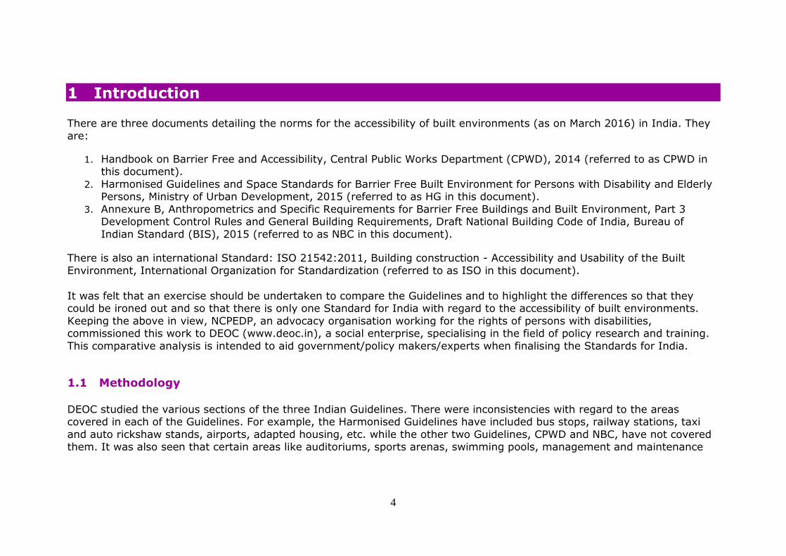
Accessibility. The signs
should not be obscured by a vehicle parked in the designated lot.
Vertical signs shall be provided, to make it easily
visible, the sign should be at a minimum height of 2100 mm.
Accessibility. The signs
should not be obscured by a vehicle parked in the designated lot.
Vertical signs shall be provided, to make it easily
visible, the sign should be at a minimum height of 2100 mm.
marked both on the
pavement with the international symbol of access and with a vertical
sign with the international symbol for accessible
parking space to indicate the location of the designated accessible
parking. The vertical sign should be
located so that it does not create a hazard.
Observations and Recommendations
1. Ratio of accessible parking spaces: The ratio given in CPWD and HG is insufficient and should be made compliant with ISO. This section in NBC has been taken from ISO, which is comprehensive. However, there is an additional point in
ISO which is, “Additionally, some designated accessible parking spaces should be provided for motorists accompanied by a child in a perambulator or pushchair and shall be designated with a perambulator sign.” This could also be added
in the NBC. 2. Location of parking: NBC and HG mention that accessible parking that serves a building should be located nearest to
an accessible entrance and/or lift lobby within 30 m whereas ISO mentions 50 m. Standard given in HG and NBC seem
better. CPWD should add the information.

27
3. Dimensions of car parking space: CPWD has not mentioned the rear space requirement, which should be added. ISO is talking of side transfer of 1500 mm whereas NBC, CPWD and HG only provides for 1200 mm transfer space. Indian
Standards could adopt the ISO with regard to the transfer space requirement. 4. Van parking: CPWD and HG have missed out on requirements for van parking. NBC mentions it but it has missed out
the transfer space or sidewalk of 2400 mm wide, though it is there in the figure. It should be added in text of NBC. 5. Head Clearance: HG and ISO mention 2400 mm for head clearance space whereas NBC states 2600 mm. HG should
be revised it to 2600 mm as given in NBC. CPWD should include this point.
6. Many specifications, signage heights, van parking, maximum distance of parking from entrance, head clearance etc. are not given in the CPWD Guidelines, which should be added.

28
5 Ramps
Dimensions CPWD HG NBC ISO
Minimum width 1800 mm. 1200 mm. Level difference/ rise and the width of Ramp:
For 150 - 300 mm: 1200 mm;
300 - 750 mm : 1500 mm; 750 - 3000mm : 1800 mm; More than or
equal to 3000mm: 1800 mm.
1200 mm. Level difference/rise and the width of Ramp
For 150 - 300 mm: 1200 mm; 300 - 750 mm: 1500 mm;
750 - 3000 mm: 1800 mm; More than or equal to 3000 mm: 1800 mm.
1200 mm. (The unobstructed width of a ramp shall be not less than
1000 mm between the handrails or any
obstructions.) Exceptional considerations in adaptation of urban areas or
at the entrance of existing buildings: The unobstructed
width of a ramp shall be not less than 900 mm.
Maximum gradient 1:12
Slope with the ratio of 1:20 (5%)
to 1:15 (6.7%)
is preferred.
Level difference and
corresponding Gradient: For 150 - 300 mm - 1:12;
300 - 750 mm - 1:12; 750 - 3000 mm - 1:15;
More than or equal to 3000: 1:20.
Level difference and
corresponding Gradient: For 150 - 300 mm - 1:12; 300 - 750 mm - 1:12;
750 - 3000 mm - 1:15; More than or equal to 3000:
1:20.
Level difference and
corresponding Gradient For 210mm: 1:12; 235 mm : 1:13;
280mm: 1:14; 315 mm: 1:15;
350mm: 1:16; 385 mm: 1:17; 420 mm: 1:18;
460 mm: 1:19; 500 mm: 1:20;
no limit: less than 1:20. A ramp with a gradient higher

29
Dimensions CPWD HG NBC ISO
than 1:12 is difficult to use
and can create a risk of an accident; it is therefore not suitable for independent use.
Exceptional considerations in adaptation of urban areas or
at the entrance of existing buildings - For 35 mm: 1:8; 375 mm: 1:8; 750 mm: 1:9;
1000 mm: 1:10; 1150 mm: 1:11; 1250 mm: 1:12.
Landing space A clear
space of not less than
ramp’s width shall be provided at
the head and foot of
every ramp, i.e. door swing
and alike shall not be
allowed to swing onto the landing.
Ramps should have a
level landing at the top and bottom of each run
and also where the run changes direction. Landings should:-
- Be provided at regular intervals of not more
than 9000 mm of every horizontal run - Have a level platform
of not less than 1500 mm;
- 300 - 750 mm landing every 5m of ramp run; 750 - 3000 mm landing
after every 9 m of ramp
Ramps shall have a level
landing at the top and bottom of each run and also
where the run changes direction Landings shall be provided at
regular intervals of not more than 9 000 mm of
every horizontal run. It shall have a level platform of not less than 1500 mm
300 - 750 mm landing every 5 m of ramp run;
750 - 3000 mm landing after every 9 m of ramp run; More than or equal to 3000
mm, landing after every 9 m
An end landing shall be
provided at the foot and the head of a sloped path, a
stepped path, or a ramp. The area of an end landing may be a part of the continuing
path. The length of an end landing
and an intermediate landing shall be not less than 1500 mm.
The length of an intermediate landing at any change in
direction of more than 10° shall be at least 1500 mm measured on the centre line.
Exceptional considerations for

30
Dimensions CPWD HG NBC ISO
run;
More than or equal to 3000 mm, landing after every 9 m of ramp run.
of ramp run. existing buildings: The clear
space at the beginning and at the end of the ramp shall be at least 1200 mm at surface
level. Intermediate landings shall also be at least 1200
mm.
Resting space outside the swing of door
A level resting
space outside the swing of
any door at the top of a
ramp should be provided to
avoid the possibility of
‘roll-back’ for wheelchair
user when trying to
open the door.
A clear, firm and level landing of at least
1800mm x 1800mm should be provided on either side of the
entrance door.
Ramps should not ideally connect straight to doors as
wheelchair users need a leveled platform at the end of the ramp to maneuver and
negotiate opening the door.
The area of a landing shall be clear of any obstruction
including the path of swing of a door or gate.
Alternate to ramp
Where the horizontal run Where the horizontal run of In addition to a ramp, a flight

31
Dimensions CPWD HG NBC ISO
of the approach ramp
exceeds 9000 mm length, an alternative stepped approach, in
addition to the ramp approach, should be
provided for people with ambulatory disabilities.
the approach ramp exceeds
9000 mm length, an alternative stepped approach, in addition to the ramp
approach, shall be provided for people with ambulatory
disabilities.
of steps should be provided if
the change in level is more than 300 mm.
Tactile warning
Single row of tactile
warning blocks should be placed at beginning and end of each ramp at also
at the beginning and end of each run.
Single row of tactile warning
blocks shall be placed at beginning and end of each ramp and also at the
beginning and end of each run.
Where required on a
continuous accessible path of travel, tactile warning indicators should be located
at both the top and bottom of ramps across the whole
width of the stair (ramp). See further details in the below row.
Placement/ measurement of tactile warning
Tactile warning blocks shall be placed 300-400 mm before the beginning
and end of each ramp/stair run.
The tactile attention pattern should have a depth of between 600 mm and 900
mm ending 300 mm to 500 mm before the front edge of
the first down going step.
32
Dimensions CPWD HG NBC ISO
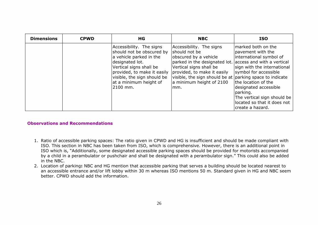
surface
Should be slip resistant.
Outdoor ramps and their surface should be designed to prevent
water from accumulating on the walking surfaces.
-Non-glary, smooth, level,
even and slip resistant even when wet; -Outdoor ramps and their
surface shall be designed to prevent water from
accumulating on the walking surfaces; and -The surface finish shall be
hard and suitable for the volume of traffic that the
ramp is likely to experience.
Rigid with a plain and slip-
resistant surface, in both wet and dry conditions.
Edge protection/guarding
along ramps
Ramps and landings not adjacent to a wall should have
an edge protection in form of a 75 mm kerb. Providing protection at the
side of the path protects people who use wheelchairs
and ambulant people from injuring themselves as the result of a fall.
If a level or sloped path is bounded on one or both sides
by terrain that slopes downwards by up to 30° from the horizontal, a firm and
level margin of at least 600
Providing protection at the side of the path protects
people who use wheelchairs and ambulant people from injuring themselves as the
result of a fall. If a level or sloped path is
bounded on one or both sides by terrain that slopes downwards by up to 30° from
the horizontal, a firm and level margin of at least 600
mm shall be provided at the relevant side or sides. If a sloped path or ramp is
bounded on one or both sides

33
Dimensions CPWD HG NBC ISO
mm shall be provided at the
relevant side or sides. If a sloped path or ramp is bounded on one or both sides
by terrain that slopes downwards by 30° or more,
an upstand of minimum height of 150 mm shall be provided at the relevant side
or sides. Upstands shall have a minimum difference in LRV
of 30 points in relation to the ramp. If a path, or a sloping path,
stepped path, ramp, terrace or other unfenced platform
rises more than 600 mm above the adjacent ground, it shall be provided with
guarding. If the adjacent ground is firm and level with
the path for 600 mm, no guard is needed.
Guarding shall be designed to discourage a user, particularly
a child, from climbing on it.
by terrain that slopes
downwards by 30° or more, an upstand of minimum height of 150 mm shall be
provided at the relevant side or sides. Upstands shall have
a minimum difference in LRV of 30 points in relation to the ramp.
If a path, or a sloping path, stepped path, ramp, terrace
or other unfenced platform rises more than 600 mm above the adjacent ground, it
shall be provided with guarding. If the adjacent
ground is firm and level with the path for 600 mm, no guard is needed. Guarding
shall be designed to discourage a user, particularly
a child, from climbing on it.
Lighting - - - The minimum illumination at

34
Dimensions CPWD HG NBC ISO
the top and bottom of the
ramp should be 200 lux and 150 lux in between the bottom and top.
Handrail See section on Handrail
Observations and Recommendations
1. Maximum gradient: ISO is better and comprehensive. For example, for a level difference of 500 mm, HG and NBC
have given the required gradient as 1:12; whereas ISO mentions 1:20. Indian Standards should adopt the ISO Standards.
2. Alternate to ramp: HG and NBC, for level difference of approximately 600 mm (9000 mm horizontal run) mentions
that alternate to ramp should be provided; whereas, in ISO it is mentioned that alternate to ramp should be provided for 300 mm level difference. CPWD has not given this point. The ISO standards should be adopted by Indian
Standards. Moreover, the reference should be with respect to level difference and not the horizontal run as it currently the case in HG and NBC.
3. Lighting: The lighting requirement has not been given in the Indian Standards. It should be added as per the ISO
Standard. 4. Edge protection/guarding along ramps: CPWD and HG have not given this point. NBC has taken the specifications from
ISO. CPWD and HG should add this point. 5. Placement of tactile warning indicators: CPWD and HG have not mentioned specifications for placing the tiles in the
ramp. CPWD and HG should add the specifications. NBC has given the distance for placing the warning indicators,
however, has not given its depth. This should be added as per ISO.

35
6 Kerb Ramps
Dimensions CPWD HG NBC ISO
Location of kerb ramps
Be provided at pedestrian crossing and at each end of the
footpath of a private street or access road.
Kerb separating footpath or ramp from vehicular area shall also
be a dropped kerb.
Be provided where the vertical rise is less than 150 mm; Should not
project into the road surface; should be
located or protected to prevent obstruction by parked vehicles; and
Should be free from any obstruction such as
signposts, traffic lights, etc. Should not be used if
they project in (The text is missing in HG)
Be provided where the vertical rise is less than 150 mm.
Shall not project into the road surface
Shall be so located and also protected to prevent obstruction by parked
vehicles. Shall be free from any
obstruction such as signposts, traffic lights, etc. Shall not be used if they
project into a roadway, as it is dangerous for users
and obstructive for vehicles. Shall be so located to enable users to have an
unobstructed view of traffic approaching from any
direction.
Be located in close proximity to the designated accessible parking area
connecting the accessible path of travel to the
principal entrance. The accessible path to the kerb ramp can be marked
with hatching painted on the road surface to prevent
people from parking in this area.
Length and width
Not less than 1200 mm in length and 1200 mm
in width; With a clearance of at least 800
The width should not be less than 900 mm min.
Not be less than 1200 mm in length and 1200 mm in
width; With a clearance of at least 800 mm long at the
Width should be a minimum of 1000 mm.

36
Dimensions CPWD HG NBC ISO
mm. long at the back of
the footway.
back of the footway.
Maximum gradient
1:12 1:12; the flared sides should not be more than
1:10.
1:12; flared side shall not be steeper than 1:10.
Level difference and corresponding Gradient:
75 mm : 1:8 ; 110 mm: 1:9; 150mm: 1:10;
180mm: 1:11.
Tactile warning
Provided with a tactile warning strip at 300 mm
from the vehicular areas; Provided with a
tactile warning strip of the nominal width of 600 mm at the ramp.
Tactile warning strip should have a minimum
luminous contrast of 70% with the adjoining surfaces.
Diagram 7.1 has some details about tactile
blocks.
They shall be provided with adequate visual and tactile
warning. Tactile warning strip (TGSI)
shall be provided to notify the presence of traffic. The tactile warning strip shall have a
minimum luminous contrast of 70 percent with the
adjoining surfaces for the elderly and persons with visual impairment.
Where required on a continuous accessible path
of travel, tactile warning indicators should be located
at both the top and bottom of ramps. See further detailed measures in the
above section on ramps.
Surface Raised traction strips shall be avoided. Dropped kerb should
have slip-resistant surface with a minimum
“static coefficient of friction” of “Very Good”
Slip-resistant surface; should be designed not to allow water
accumulating on the walking surface.
Slip-resistant surface with a minimum static coefficient of friction of 'very good'
grading. They shall avoid raised
traction strips in order to reduce the hazard to
Slip-resistant surface.

37
Dimensions CPWD HG NBC ISO
grading. everyone.
They shall be designed not to allow water accumulating on the walking surface.
Handrail
Not required Not required Not required
Observations and Recommendations
1. Location of kerb ramps: Some text is missing in HG on page 56. It should be corrected. 2. Length and width: CPWD and NBC standards mention minimum width of 1200 mm whereas HG mentions 900 mm and
ISO 1000 mm. HG should adopt the CPWD and NBC Guidelines for the width of kerb ramp. 3. Maximum gradient: ISO gives different gradient for different heights for kerb ramps compared to CPWD, NBC and
HG. However, CPWD, HG and NBC standard of 1:12 is more suitable.
4. Tactile Warning Indicators: In HG and NBC the text should elaborate the Standards for laying them apart from just indicating them in diagram.
38
7 Handrails
Dimensions CPWD HG NBC ISO
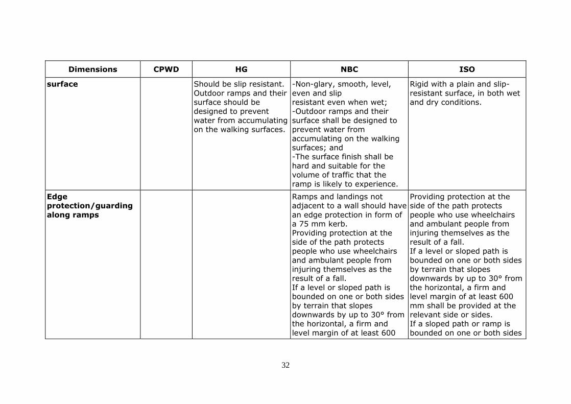
Provision of
handrails
Handrails must be
continuous on both sides & even at
landings.
For stairs and ramps,
handrails shall be provided on both the
sides; and be continuous, even at the landings.
Be provided on both sides
of all flights of stairs, and a central handrail should be
provided when the unobstructed width of the stairs exceeds 2700 mm,
provided that an unobstructed width of at
least 1500 mm is provided on one side. Exceptional considerations
for existing buildings: a handrail should be provided
on at least one side of the flight of stairs (principal difficulties arise in relation
to heritage buildings).
Profile of handrails
Be fixed not less than 35 mm and not more than 50
mm clear of wall and with a clear height of 70 mm from
the top of the bracket to
-Be slip-resistant with round ends;
-have a circular section of 38-45 mm in
diameter;
-Be slip-resistant with round ends;
-Have a circular section of 38-45 mm in
diameter;
-Have a rounded profile that can be inscribed into a
45 mm circle, and subscribed to a 35 mm
diameter circle. The radius

39
Dimensions CPWD HG NBC ISO
the top of the handrail.
Handrail shall be tubular, not less than 40 mm and not greater than 50 mm in
external diameter and in other shapes that can
provide the user a grip similar to that specified in the case of tubular
handrails. Where the wall has a rough
surface, the clear space should be not less than 45 mm between the handrail
and the wall.
-Have a minimum clear
space of 50 mm from the walls; -Be free of any sharp
or abrasive elements;
-Have a minimum clear
space of 50 mm from the walls; -Be free of any sharp
or abrasive elements;
of the rounded edges shall
be minimum 15 mm;
-Be located to provide a minimum clear space of 40
mm from an adjacent wall or other obstruction;
-Have an overall projection from any side obstruction of not more than 100 mm;
-Have the top 270° arc of the handrail clear along its
full length;
-Have a minimum of 50 mm clearance under the
270° arc along the full length of the handrail for
finger indentation;
-Have a surface that is smooth but provides
adequate resistance to hand slippage.
NOTE: A wide and

40
Dimensions CPWD HG NBC ISO
relatively flat-topped
surface on a handrail provides better support than a regularly curved
one. Graspability is better on a handrail that does not
require significant hand and finger joint movement. For these reasons, the use
of a handrail that is elliptical is preferred.
Continuity
of a handrail
Handrails must be
continuous on both sides & even at
landings. Handrail should have continuous gripping
surfaces, without interruptions or
obstructions that can break a hand hold.
Handrails should Have
continuous gripping surfaces, without
interruptions or obstructions that may break a hand hold.
Handrails should be
continuous throughout the flight of a ramp, stair,
stepped path and intermediate landing, except where they
intercept with a doorway or path of travel.
Height of a
handrail
The top of handrail shall be
at a height of not less than 850 mm and not more than 950 mm above any nosing,
The handrails are
placed at a height of between 760 mm and 900 mm above the
Be installed at a height
of 700 mm to 900 mm (to be measured from the centre line of the
The height to the top of a
handrail shall be between 850 mm and 1000 mm above the surface of a

41
Dimensions CPWD HG NBC ISO
floor or landing.
One more handrail should be provided at a height of not less than 700 mm and
not more than 800 mm above any nosing, floor or
landing for schools and places of public entertainment.
floor level. circular handrail across
its diameter).
ramp, the pitch line of a
stair, and the surface of a landing. A second handrail, with a
lower profile than the first one, shall be provided. The
height to the top of the second handrail should be between 600 mm and 750
mm above the surface of a ramp, the pitch line of a
stair, and the surface of a landing.
Horizontal
extension of a handrail
Handrail shall extend
horizontally not less than 300 mm beyond the first and last nosing of every
flight of steps or beyond the ends of a ramp and
terminate into a closed end which shall turn down or return fully to end post or
wall face and which shall not project into a route of
travel. A recess containing a handrail should extend not
Handrails should -
Extend horizontally for a distance of not less than 300 mm beyond
the top and bottom of the ramp to provide
support for persons who may need help to negotiate the ramp;
and not project into another path of travel.
Handrail extensions
shall: -Extend horizontally for a distance of not less
than 300-450 mm beyond the top and
bottom of the ramp to provide support for persons who may need
help to negotiate the ramp; and
- Not project into another path of travel. - In case the handrail is
A handrail on a stepped
path, stair or ramp shall have a horizontal extension of not less than 300 mm
beyond the first and last nosing of each flight.
A handrail shall not project into a transverse circulation path unless it is
continuous and intended to form part of the guidance
along that path. The end of the horizontal extension should be turned

42
Dimensions CPWD HG NBC ISO
less than 450 mm above
the top of the handrail.
enclosed in a recess,
the recess shall extend at least 450 mm above the top of the rail.
Handrails shall turn in towards the wall at
either end.
towards the wall on the
closed side of the ramp or stairs, or be turned down and terminate at the floor
or ground level. NOTE: This provision
supports people with mobility impairment and limits the risk of clothing
being caught.
Visual and tactile
information
Handrail should have a minimum luminous contrast
of 30% with the surrounding wall surfaces.
Handrail finished in more noticeable colors with Braille and tactile
information should facilitate self-help circulation of
persons with visual impairment Braille and tactile
information on directional arrow and floor number
shall be provided on handrail on every floor at a designated location to
Handrails may be provided with Braille/
tactile markings at the beginning and the end
to give information to people with visual impairment.
Handrails may be provided with
Braille/tactile markings at the beginning and at
the end to give information to people with visual impairment.
To aid identification, the colour of the rail
shall contrast with the wall behind.
The minimum visual contrast of a handrail to
the adjacent background should be as per standards
on visual contrast.
Raised text or tactile symbols shall be
unobtrusively and permanently fitted or fixed
to handrails as an important source of information for people who
have a vision impairment, e.g. indication of floor
number, direction of fire evacuation, location of final

43
Dimensions CPWD HG NBC ISO
facilitate persons with
visual impairment. Where a directional sign exists on handrails, Braille
and tactile information shall also be provided.
fire exits, etc.
Mechanical
resistance
Handrail shall be installed
to resist a load of not less than 1.3 kN applied
vertically or horizontally. Handrail shall not rotate within its fixing fittings.
The handrail shall be
securely fitted to the wall to withstand heavy
pressure.
Handrails shall be securely
fixed and rigid. The fastenings and the
materials shall be able to withstand a minimum point load, both vertical and
horizontal, of 1.7 kN.
Observations and Recommendations
1. Provision of handrails: ISO mentions a central handrail for wider staircases/steps. This is missing in the Indian Standards and should be incorporated.
2. Profile of handrails: ISO recommends an elliptical profile of handrail and the details for the same are also mentioned. This is for better graspability and the Indian Standards should adopt the same.
3. Height of handrails: The ISO Standards mention a second handrail to be installed at a lower height. This is missing in
HG and NBC and should be incorporated. 4. Visual and tactile Information: The colour contrast of the handrail against the wall (value) should be specified in HG
and NBC. 5. Mechanical Resistance: It would be ideal to specify the force to withstand in NBC and HG as specified in CPWD and
ISO.

44
8 Staircase
Dimensions CPWD HG NBC ISO
General Where steps or stairs are
in an accessible route, complementary ramps, lifts
or escalators should be provided.
Winder, spiral staircase and splayed step should be avoided. Circular stair and
sloped landing should be avoided.
Stairs should not be
the only means of moving between
floors. They should be supplemented by lifts and /or ramps.
Also, spiral stairs should be avoided.
Steps and staircases are
intended as an alternative to lift access in buildings
and shall be of adequate design to allow all persons, with or without a
disability, to travel safely and independently. Stairs
shall not be the only means of moving between floors. They shall be
supplemented by lifts and/or ramps.
Spiral stairs shall be avoided.
Spiral and curved stairs
are not recommended.
Rise and
going of steps
Treads not less than 300
mm in width.
Risers not more than 150
mm in height.
Individual flight should not
exceed 1800 mm in height
Treads should be 300
mm deep. Risers not higher than 150 mm.
There should be no more than 12 risers in
one flight run. Steps should be of a
Treads shall be 300 mm
deep. Risers not higher than 150 mm.
There shall be no more than 12 risers in one flight
run. Steps shall be of a
Going of a step should be
not less than 300 mm. The minimum going of the tread shall be 260
mm, and the maximum rise shall be 180 mm. The
rise and tread of steps within flights shall be

45
Dimensions CPWD HG NBC ISO
nor a total of 11 risers.
Open risers should be avoided. All steps should be uniform.
consistent height and
depth throughout the staircase. Open stairs shall not
be provided to minimize the risk of
stumbling.
consistent height and
depth throughout the staircase. open stairs shall not be
provided to minimize the risk of stumbling.
uniform.
A flight of steps should not contain more than 16 risers. However, in
circumstances where the plan area is restricted, a
flight of a stairs shall contain no more than 20 risers.
Should spiral and curved stairs be used, the inside
handrail should have the inside edge vertically parallel with the going at a
point where the depth of the going is a minimum of
220 mm. The sum of the going and twice the rise of a step should be not less
than 600 mm and not more than 660 mm.
The riser of a step shall not be open.
Nosing The risers built with
vertical or receding face not more than 15 mm from the vertical, without a
Projecting nosing and
open stairs should not be provided to minimize the risk of
Projecting nosing and
open stairs shall not be provided to minimize the risk of stumbling.
The projection of a step
nosing over the tread below shall be avoided but, if necessary, shall not

46
Dimensions CPWD HG NBC ISO
projecting nosing. It shall
be provided with non-slip nosing in contrasting colour.
stumbling. be more than 25 mm. The
nosing shall provide an uninterrupted transmission between riser
and tread.
Minimum width of
stair flights
. The stairs should have minimum 1500 mm
clear width.
The stairs should have minimum 1500 mm clear
width. However, in no case the clear width of the
staircase shall be reduced below 1200 mm.
The minimum width of a flight of stairs shall be
1200 mm.
The minimum width between handrails shall be
1000 mm.
Exceptional considerations
for existing buildings in developing countries: In
some member states, the minimum width of a flight of stairs may be reduced
to 900 mm and the minimum width between
handrails may be reduced to 800 mm.
For Fire exit staircase: be
not less than 1500 mm.

47
Dimensions CPWD HG NBC ISO
Avoidance
of projection
No appliances, fixtures or
fittings shall project beyond 90 mm from the surface of any wall in a
staircase below a level of 2000 mm above the treads
of the staircase unless they are unavoidable, in which case they shall also be
extended downwards to the level of the treads.
No appliances, fixtures or
fittings shall project beyond 90 mm from the surface of any wall in a
staircase below a level of 2000 mm, measured
above the treads of the staircase. If such a projection is unavoidable,
the same shall also be extended downwards to
the level of the treads.
Staircase landings
The stairs landing should be minimally
1200 mm deep.
The stairs landing should be minimally 1200 mm
deep.
The area of a landing shall be clear of any obstruction
including the path of the swing of a door or gate. Where there is a half
landing or a 180° turn, it shall never be less than
1500 mm wide in order to facilitate. carrying a person on a stretcher.
If the stepped path is multi-channelled, the
length of an intermediate

48
Dimensions CPWD HG NBC ISO
landing shall not be less
than the unobstructed width of the widest channel.
Head clearance
Soffit of the stairs, shall be cordoned off either by building a wall in front of
it or by putting handrails to guide persons around
the space.
Clear accessible height under stairs shall be a minimum of 2100 mm or
greater. If the clear height is less than 2100 mm, a
guard or other element shall be provided to shield against impact.
Head clearance on the stair shall be minimum
2100 mm.
Colour contrast and
visual warning
Treads and walls of a staircase shall be in
contrasting colours.
Step edges must contrast in colour to
the risers and the treads. Contrast colour bands 50 mm
wide should be provided on edge of
the tread. There
There shall be colour contrast between
landings, and the steps. Step edges shall contrast in colour to the risers and
the treads. Contrast colour bands 50 mm wide
shall be provided on edge
There shall be a visual contrast between landings
and the top and bottom step of a flight of stairs.
Preferably, a visual
warning line with a single strip of 40 mm to 50 mm
without a break shall be

49
Dimensions CPWD HG NBC ISO
should be colour
contrast between landings, and the steps.
of the tread.
provided on the front edge
of the going of each step with a minimum difference in LRV of 60 points and
may return down the riser for a maximum of 10 mm.
The visual indicator on the going may be set back a maximum of 15 mm from
the front of the nosing. As an alternative solution, a
visual warning line with a width between 50 mm and 100 mm shall be provided
on the going of the first and the last step of the
flight.
Tactile warnings
and information
Tactile warning strips shall be provided at landings
and at both the bottom and top ends of a staircase, regardless of the
number of steps it comprises. For landings
leading to a floor or those enclosed by wall, railing or
Warning blocks should be installed 300 mm
before the beginning and 300 mm after the end of each flight of
steps to aid people with visual
impairments.
Tactile ground surface indicators (warning type)
shall be installed 300 mm before the beginning and 300 mm after the end of
each flight of steps of external affairs to aid
people with visual
Where a stair is in an open area, a tactile attention
pattern may be beneficial. National regulations can require the systematic use
of tactile warning on any stair. However, where
different materials are used for the flights and

50
Dimensions CPWD HG NBC ISO
balustrade, tactile warning
strips of 300 mm in width shall be provided; for those leading to an open
space or the entrance / exit of a building, the
tactile warning strips shall be 600 mm in width. In this case, Braille and
tactile information signs shall be provided on the
adjacent wall to indicate the presence of an opening. For a staircase
with intermediate steps between two flights, the
provision of tactile warning strips shall follow the arrangement in.
impairments.
Tactile warning strips shall be provided at landings and at both the bottom
and top ends of a staircase, regardless of
the number of steps it comprises. For landings leading to a floor or those
enclosed by wall, railing or balustrade, tactile warning
strips of 300 mm in width shall be provided; for those leading to an open
space or the entrance/exit of a building, the tactile
warning strips shall be 600 mm in width. In this case, Braille and tactile
information signs shall be provided on the adjacent
wall to indicate the presence of an opening. For a staircase with
intermediate steps between two flights, the
provision of tactile
landings of a stair, care
should be taken to ensure that their frictional characteristics are similar
in order to minimize the risk of stumbling.
Where tactile attention patterns are used, they should be provided on the
landings at the top and bottom of every flight of
stairs across the whole width of the stair. The tactile attention pattern
should have a depth of between 600 mm and 900
mm ending 300 mm to 500 mm before the front edge of the first down
going step.
Where tactile attention
patterns are used at the top and bottom of stairs, the attention pattern shall
not reduce visual detection of the first and

51
Dimensions CPWD HG NBC ISO
warning strips shall follow
the same arrangement.
the last step of the flight.
Guards along stairs
If a stair rises more than 600 mm above the
adjacent ground, it shall be provided with guards from that point on.
Lighting Illumination level of 100-
150 lux shall be maintained on the stairs.
The minimum illumination
at the top and bottom of the flight should be 200
lux and 150 lux in between.
Materials
and finishing
The materials selected for
the surface finish of the stairs shall be firm and slip resistant, especially if
surfaces are likely to become wet due to
location or use, or if spillage occurs. Slippery
surfaces like granite, glazed tiles are best avoided.

52
Dimensions CPWD HG NBC ISO
Shiny, polished surface
materials that cause glare shall not be used for stairs or ramps.
Observations and Recommendations
1. General: CPWD Guidelines mention that “Where steps or stairs are in an accessible route, complementary ramps, lifts or escalators should be provided”. The term ‘escalator’ should be removed from here. There should not be a choice
between escalators and lifts. 2. Number of steps is a flight of stairs: The total number of steps in one flight of stairs is different in different Guidelines.
The CPWD says 11, in HG and NBC, it is 12 and ISO says 16. Indian Standards should be established and should be
the same in all Guidelines. 3. Minimum width: CPWD Guidelines should mention the minimum width of staircase. Clear width of staircase between
the handrails should be specified in CPWD, HG and NBC as given in the ISO. NBC though mentions 1500 mm as the minimum width, it also says that in no case it should be less than 1200 mm. It may be useful to add in the NBC that for fire exit staircases the width should be 1500 mm.
4. Landings: Staircase landing Standards should be taken from ISO in all Indian standards as the same takes into account turning space for stretchers etc.
5. Head clearance: Head clearance for staircase should be specified in Indian Standards as given in the ISO. 6. Visual and tactile warning: Specifications for visual contrast are more elaborate in ISO and should be adopted in
Indian Standards as well.
7. Lighting: Requirements for minimum illumination level is missing in CPWD and HG. It’s there in NBC but lower than the ISO. ISO Standards should be adopted.
8. Guard along stairs: ISO mentions guards along staircase. This should be adopted in Indian Standards.

53
9 Doors and Windows
Dimensions CPWD HG NBC ISO
Minimum width of doors
Not less than 900 mm between the open door
and opposite jamb or the other leaf.
The minimum clear opening of doorways
should be 900mm, measured between the
face of the door and the face of the door stop with the door open at
90°..
The minimum clear opening of doorways shall be 900
mm, measured between the face of the door and the
face of the door stop with the door open at 90°.
The minimum unobstructed width of an
entrance doorway shall be not less than 800 mm;
850 mm or more is recommended Note: Many national
building regulations require a minimum width
of 900 mm for an entrance door.
Clear height of
a doorway
The minimum clear height
of a doorway shall be not less than 2000 mm.
Wheelchair
maneuvering space
Corridor should have a
width of at least 1200 mm to allow a 90° turn to be made through a
door. In narrow spaces sliding doors may be
preferable.
A corridor shall have a width
of at least 1200 mm to allow a 90° turn to be made through a door. In narrow
spaces, sliding doors may be preferable.
Front approaches to pull side of swinging doors shall have maneuvering space
that extends 600 mm minimum beyond the latch
Level maneuvering area
on either side of the door, if any door is opening towards a descending
stair, the minimum safe distance for maneuvering
should be 2000 mm, including doorswing, to minimize the risk for
wheelchair users. In front of the door opening into
54
Dimensions CPWD HG NBC ISO
side of the door, if 1200 mm
minimum is provided perpendicular to the doorway; or maneuvering
space that extends 450 mm minimum beyond the latch
side of the door shall be provided, if 1500 mm minimum is provided
perpendicular to the doorway.
Front approaches to push side of swinging doors shall have maneuvering space
that extends 300 mm minimum, beyond the latch
side of the door and 1200 mm minimum, perpendicular to the
doorway.
the building, there should
be a minimum horizontal maneuvering space of 1500 mm by 1500 mm.
Where turning 180° in a wheelchair may be
required, there shall be a minimum of 1600 mm by 2150 mm.
Unobstructed area to reach
/operate the handle
The unobstructed area adjacent to the door
handle on the leading face of a single door
shall not be less than 330 mm in width. Door, if less than 330 mm from
the corner of a room,
Wheelchair maneuvering spaces
should be free of any obstructions and space
should be provided on the side of the door handle in the following
manner:
Wheelchair maneuvering spaces shall be free of any
obstructions and be provided on the side of the
door handle in the following manner: - On the pull side, a
minimum space of 650 mm;
A clear space of 600 mm (700 mm recommended)
at the latch side of the door is required to allow
someone to operate the door handle. The maximum distance
from the handle of the

55
Dimensions CPWD HG NBC ISO
shall swing from the side
nearer to that corner.
- On the pull side, a
minimum space of 650 mm; - On the push side, a
minimum space of 300 mm;
- For two-way swing door, a minimum space of 300mm.
- On the push side, a
minimum space of 300 mm; and - For two-way swing door, a
minimum space of 300 mm.
door leaf to the wall
surface shall not exceed 250 mm. Design, installation and
maintenance of sliding doors should be specially
considered. A maneuvering space of not less than 600 mm
shall be provided between the leading edge of a door
and a wall that is perpendicular to the doorway; 700 mm or
more is recommended.
Two doors in series
The minimum space between two hinged or
pivoted doors in series should be 1200 mm
plus the width of the door swinging into that space.
The minimum space between two hinged or
pivoted doors in series, shall be 1500 mm plus the width
of the door swinging into that space.
Double-action self-closing doors
Double-action self-closing door shall have a check mechanism to
prevent the door swinging beyond the

56
Dimensions CPWD HG NBC ISO
closed position and a
transparent vision-panel with a bottom edge not more than 1000 mm
above the floor and the top edge not less than
1500 mm above the finished floor level.
Height of
handles
Door handle shall not be
less than 950 mm and not more than 1050 mm above the finished floor
level, measured from the top surface of the grip.
Be mounted at a height
of 850 mm to 1100mm from the floor. -Push –pull mechanisms
that require no grasping;
- Lever handles to be preferred on latched doors;
- It is safer to use D shaped handles as they
reduce the risk of catching on clothing, or injuring
from the exposed lever end.
- Doorknob is not recommended.
Be mounted at a height of
850 mm to 1100 mm from the floor. -Push-pull mechanisms that
require no grasping; - Lever handles to be
preferred on latched doors; - It is safer to use D-shaped handles as they reduce the
risk of catching on clothing, or injuring from
the exposed lever end; and - Doorknob is not recommended.
Door furniture shall be
located between 800 mm and 1000 mm in height, preferably 900 mm.
Door locks, door handles, bells and other devices for
gaining entry to a place shall be easy to locate, identify, reach and use,
and shall be operable with only one hand. D-lever
handles are preferred.
Door thresholds Door threshold shall not There should be no There shall be no thresholds Entrances into the building

57
Dimensions CPWD HG NBC ISO
exceed 20 mm in height
and shall be beveled to facilitate passage of wheelchairs.
thresholds.
If thresholds are unavoidable, they should not exceed 12
mm and those exceeding 5 mm should
be beveled.
(doorsills). If thresholds are
unavoidable, they shall not exceed 12 mm and those exceeding 5 mm shall be
beveled.
should be level. Any
raised threshold shall not exceed 20 mm. Where a raised threshold
is necessary, it shall have maximum height of 20
mm, be bevelled down, and have a minimum difference in LRV of 30
points compared to the floor.
Kick-plates All doors which allow the
passage of wheelchairs should have kick-plates
of not less than 200 mm high fitted on the face which swings away.
Kick- plates of 300-400
mm height (Figure 5-25) are recommended
for doors in high use in order to protect the push side of doors from
damage.
Kick-plates of not less than
300-400 mm height are recommended for doors in
high-use in order to protect the push side of doors from damage.
Door identification
The presence of door, whether opened or
closed, should be apparent to persons with
visual impairment through the careful choice of colour and
materials for the door and its surroundings.
To help people with impaired sight to see
doors, the door and frame should be in a
colour which contrasts with the adjoining wall. The door should not be
of a highly polished/ reflective material such
To help people with impaired sight to see doors,
the door and frame should be in a
colour which contrasts with the adjoining wall. The door shall not be of a highly
polished/reflective material such as stainless steel.
Doors forming part of an accessible path of travel
shall have a difference in light reflectance value to
doorframe and the surrounding wall of not less than 30 points, The
minimum width of the area of visual contrast

58
Dimensions CPWD HG NBC ISO
Provision of marking on
glass doors would help persons with visual impairment to
distinguish obstacles and passage as well as for
public to avoid collision. Door handle of manually operated doors
and control switch or button of door with
powered open devices should have a minimum luminous contrast of
30% with the background finishes.
as stainless steel. shall be 50 mm. If this is
not possible to achieve, a marking of at least 50 mm width (e.g. around the
frame of the door), with a different visual contrast
from the wall (with a minimum difference in LRV of not less than 30
points) shall surround all the perimeter of the door.
There should be a visual contrast between the door leaf and the handle of at
least 15 points.
Vision/viewing
panels
Should be installed with
bottom edge not more than 1000 mm and top
edge not less than 1500 mm above the finished floor level.
Panel giving visibility
from a height of 800 mm to 1500 mm.
Panel giving visibility from a
height of 800 mm to 1500 mm.
The lower edge of the
glazed panel shall be not more than 600 mm above
the finished floor, the upper edge of the glazed panel shall be not less
than 1600 mm above the finished floor, in width,
the glazed panel shall start not more than 200 mm from the latch edge of
the door, and the glazing

59
Dimensions CPWD HG NBC ISO
shall be not less than 150
mm wide, the glazed panel may be subdivided by narrow construction
cross-sections of a maximum width of 200
mm.
Visual indicator on glass doors
The leading edge of glass door should be
marked to indicate glass. "If frameless glass door is used, it shall be
prominently marked so as to make it visible.
The marking shall be placed across on the glass door such that at
least a portion of the marking is placed
between 900 mm and 1500 mm above the finished floor. The
colour marking shall also be provided to glass
panel adjacent to the glass door."
The presence of a glass door should be made
apparent, with permanent manifestation at two
levels, within 800 mm to 1000 mm from the
floor and within 1400 mm to 1600 mm from the floor ,
contrasting visually with the background seen
through the glass in all light conditions. The edges of a glass door
should also be apparent when the door is open.
Note: If a glass door is adjacent to, or is incorporated within, a
fully glazed wall, the
The presence of a glass door shall be made apparent,
with permanent manifestation at two levels, within 850 mm to 1000 mm
from the floor and within 1400 mm to 1 600 mm from
the floor, contrasting visually with the background, seen through
the glass in all light conditions. The edges of a
glass door shall also be apparent when the door is open. Note: - If a glass door
is adjacent to, or is incorporated within, a fully
glazed wall, the door and wall shall be clearly differentiated from one
another, with the door more
Glazed (glass) walls and fully glazed doors shall be
clearly marked with visual indicators. Large glazed areas close to circulation
spaces could be mistaken for openings. Glazed
walls, doors and other areas of full height glazing are very disorientating for
blind or partially sighted people. The reflections
from these surfaces can be particularly confusing. Uninterrupted visual
indicators of at least 75 mm height with a
difference in light reflectance values of minimum 30 points to the
background shall be

60
Dimensions CPWD HG NBC ISO
door and wall should be
clearly differentiated from one another, with the door more
prominent. To achieve this, the door may be
framed on both sides and the top by an opaque high-contrast
strip at least 25 mm wide.
prominent. To achieve this,
the door may be framed on both sides and also on the top by an opaque high-
contrast strip at least 25 mm wide.
placed at a height of 900
mm to 1 000 mm and 1300 mm to 1400 mm above floor level. An
additional visual indicator placed at a height of 100
mm to 300 mm is recommended. Visual indicators consisting of
two separate colours with a minimum difference in
LRV of 60 points are recommended to enable lighting conditions and
backgrounds to be taken into account.
Door opening
force
Horizontal force of not
more than 30 N and 22 N respectively. Door
required to have fire resistance period installed along accessible
routes shall be opened with horizontal force of
not more than 30 N.
The maximum force for
pushing or pulling or sliding a door should be
20 N.
The maximum force for
pushing or pulling or sliding a door shall be 20 N.
When the operating force
needed to open the door is greater than 25 N, an
automatic opening door is recommended. People with impaired
mobility often experience difficulties when using
self-closing doors. The force required to open doors should be 25 N.
Self-closing doors should

61
Dimensions CPWD HG NBC ISO
have an opener.
Buildings for public use should preferably have automatic doors or
controlled door closing devices with a hold- open
device. An alternative option is the use of dual powered controlled door
closing devices with electromagnetic retention
for higher power spring.
Door closure speed
A closing period of at least 3 seconds
measured from an open position of 70° to a point 75 mm from the closed
position measured from the leading edge of the
door.
The sweep period of the door should be
adjusted, so that from an open position of 90 degrees the door
does not take less than 3 seconds to move to a
semi-closed position.
The sweep period of the door should be adjusted, so
that from an open position of 90°, the door does not take less than 3 sec to
move to a semi-closed position.
Windows
Unobstructed viewing zone between 600mm
and 1400mm. -Curtain or Venetian blind controls/ropes
should be at 800-1000 mm height
Unobstructed viewing zone between 600 mm and 1400
mm. - Curtain or venetian blind controls/ropes shall be at
800-1000 mm height from the finished floor
The lower edge of the glazing should be no
higher than 1100 mm from the floor. Hardware, shutters and
switches for remote control should be placed

62
Dimensions CPWD HG NBC ISO
from the finished floor
level. - Handle should be located at a height of
between 600 mm to 1100 mm from the
floor. For the requirements for handles, also see
the Door section.
level.
For the requirements for handles, also see the Door section.
between 800 mm and
1100 mm above the floor. Opening windows shall not project into pedestrian
areas below a height of 2100 mm.
For the requirements for handles, also see the Door section.
Observations and Recommendations
1. Height of doorway: Only ISO has given the minimum clear height of a doorway which shall be not less than 2000
mm. CPWD, HG and NBC should add this point. 2. Maneuvering space: CPWD has not mentioned about the maneuvering space required on either sides of the door.
NBC says that space is required beyond the latch side of the door for the pull and push. HG should add the point. ISO gives requirement for turning space in case 180 degree turn is required or if staircase is there. These should be incorporated in the Indian Standards.
3. Unobstructed space to reach the handle: HG and NBC are comprehensive with regard to minimum space required on push side and pull side. CPWD should update the Standards and make it in line with HG and NBC.
4. Two doors in a series: HG mentions that “the minimum space between two hinged or pivoted doors in series should be 1200 mm plus the width of the door swinging into that space”. However, NBC mentions 1500 mm. CPWD has not covered this. CPWD should add this point and HG should revise it as per NBC.
5. Double-action self-closing door: Only CPWD gives requirement for Double-action self-closing door. HG, NBC should add this point too.

63
6. Height of handles: Standards given in HG and NBC are the same, i.e. 850 to 1100 mm; in CPWD it is 950 to 1050 mm and in ISO it is between 800 and 1000 mm. ISO Standards seem more suitable and should be adopted by
Indian Standards. 7. Door threshold: CPWD should adopt the specification given in HG and NBC with regard to the maximum height of
thresholds. In addition, ISO provides LRV requirement and should be adopted in all Indian Standards. 8. Kick plates: CPWD mentions that “all doors which allow the passage of wheelchairs should have kick-plates of not
less than 200 mm high fitted on the face which swings away.” HG and NBC say the height should be 300-400 mm.
The standard given HG and NBC is better and CPWD should adopt the same. 9. Door identification: CPWD and ISO give the LRV requirement of door with the surrounding. ISO is comparatively
more comprehensive. HG and NBC should add the information from ISO. 10. Vision panel: HG and NBC have given the lower edge requirement as 800 mm while CPWD has given 1000 mm and
ISO 600 mm. ISO seems more suitable and all Indian Standards should adopt the ISO Standard. ISO also gives
width of glazed panel. This should also be added in Indian Standards. 11. Visual indicators on glass doors/panels: HG and NBC requirements are more or less similar and it mentions
manifestation at two levels. CPWD has given different requirement and provides for marking at only one level. ISO has provided for visual indicators at three levels. ISO has also given requirements for width of visual indicators and LRV requirements. ISO is more comprehensive. This should be adopted in Indian Standards.
12. Door opening force: HG and NBC mention that the maximum force for pushing or pulling or sliding a door should be 20 N. CPWD says 22 N and ISO say 25 N. HG and NBC standards are fine. CPWD should revise the Standard to
make it 20 N. 13. Door closing speed: HG and NBC have same requirements. CPWD should revise the Standards as per HG and NBC.
14. Different types of doors: ISO has also given specification for revolving door, sliding or folding door, powered swing door and automatic opening doors. These should be adopted by Indian Standards (pages 52 and 53 of ISO).
15. CPWD should add a section on windows. ISO has given that windows should not open in pedestrian area below
height of 2100 mm. This should be included in HG and NBC.

64
10 Elevators and Lifts
Dimensions CPWD HG NBC ISO
Minimum inner
dimensions of lift car
2000 mm x 1100 mm 1500 mm wide x 1500
mm deep; wherever possible, 13 passenger lift to be provided,
which allows easy maneuverability of
wheelchair user.
1500 mm wide x 1500
mm deep, that allows Easy maneuverability of wheelchair users.
1100 mm x 1400 mm.
If a trolley with a stretcher is considered, the minimum inner
dimensions of cars shall be 1200 mm x
2300 mm. If an entrance is provided on two
adjacent sides, the minimum inner
dimensions of cars shall be 1600 mm x 1400 mm.
Lift signage Lifts should be marked with the symbol of accessibility and
directional signs be provided to the lifts.
Signs indicating the location of an accessible lift should be provided
in a location that is clearly visible from the
Lifts shall be marked with the international symbol of accessibility.
Directional signs indicating the location
of an accessible lift shall be provided at a location that is clearly
visible from the building entrance. The
The lifts shall be marked with signage as set in the standards
showing that they fulfill minimum accessibility
requirements.

65
Dimensions CPWD HG NBC ISO
building entrance. The
sign should incorporate a representation of the International Symbol
for Access. A sign indicating the
number of the floor should be provided on each lift landing on the
wall opposite the lift. It is also recommended to
install a floor directory of the main facilities and services available
on the lift landing, along with an accessible
emergency egress route that clearly indicates the location of nearest
refuge areas for Persons with
Disabilities.
directional signs shall
incorporate a representation of the International Symbol of
Accessibility. A sign indicating the
number of the floor arrived shall be provided on each lift
landing on the wall opposite the lift in big
fonts with good colour contrast. It is recommended to
install a floor directory of the main facilities
and services available on the lift landing, along with an accessible
emergency egress route that clearly indicates
the location of the nearest refuge area for persons with
disabilities.
Lift car entrance — Door opening
Clear entrance width: 900 mm.
Clear opening of not less than 900 mm and
Clear opening of not less than 900 mm and
The unobstructed entrance width shall be

66
Dimensions CPWD HG NBC ISO
Lift car doors and landing
doors shall be of the horizontally sliding type, power- operated and
automatically controlled. An audible signal shall be
provided to signify the closing of the doors to alert persons. A detection
device shall be provided to re- open the lift doors
in the event of hitting any obstacle. The detection device shall
be positioned at a height of between 500 mm to
600 mm above the floor of the lift car. Lift door systems should
be designed to allow adequate time for
passage of persons with a disability and the elderly. Where planning allows,
lift cars may be provided with opposing doors to
allow a wheelchair user to leave without having to
contrasting in colour
from the adjoining wall. There should be no difference in level
between the lift door and the floor surface at
each level. The gap between the lift door and building floor
should not be more than 12 mm.
Time of closing of an automatic door should be more than 5 seconds
and the closing speed should not exceed 0.25
meters per second.
contrasting in colour
from the adjoining wall. There shall be no difference in level
between the lift door and the floor surface at
each level. The gap between the lift door and building floor shall
not be more than 12 mm.
Time of closing of an automatic door shall be more than 5 sec and
the closing speed shall not exceed 0.25 m/s.
at least 800 mm; 900
mm is preferred. If a trolley with a stretcher is considered,
the minimum unobstructed entrance
width: 1100 mm. The car and landing doors shall be
constructed as automatic power
operated horizontally sliding doors. The colour and tone of the
lift entrances should contrast with the
surrounding wall finishes. The door opening time shall be
adjustable to suit the conditions where the
lift is installed (normally between 2 s and 20 s). A
mechanism to increase this time shall be
installed to be customized by a user

67
Dimensions CPWD HG NBC ISO
reverse. with mobility
impairments (e.g. by means of a button outside the car to call
the lift to the floor for it to arrive with extended
door opening time, and a button marked with a wheelchair symbol
inside the car with the same purpose).
A presence sensor device shall cover the opening over the
distance between at least 25 mm and 1800
mm above the car door sill (e.g. light curtain). The device shall be a
sensor which minimizes the likelihood of
physical contact between the user and the leading edges of
the closing panel(s).
Maneuvering space outside
The maneuvering space should not be in any
68
Dimensions CPWD HG NBC ISO
the lift entrance circulation route nor
directly opposite to any stair circulation. If a stair is situated
opposite the entrance, the distance to the stair
shall be at least 2000 mm to allow safe maneuvering. The
maneuvering area shall be adequately lit with a
minimum illumination of 100 lux. A maneuvering space
of 1200 mm X 1200 mm can be accepted
according to national regulations and national standards, but
could lead wheelchair users to dangerous
situations. In order to aid in location of the lift
entrance, a distinguishable floor
surface of approximately 1500

69
Dimensions CPWD HG NBC ISO
mm X 1500 mm should
be installed outside the doors. This could be obtained by means of a
change of colour or floor finish. Changes in
floor finish should be flush.
Handrail/grab
bars
The top of the gripping
surface of the handrails shall be at a height of 850 mm – 950 mm, with a
space of 30 mm - 50 mm between the handrails
and wall.
Grab bars should:
Be placed at a height of 900 mm from the floor level; and be fixed on
both sides and at the rear of the lift.
Grab bars shall be
placed at a height of 900 mm from the floor level. These shall be
fixed on both sides and at the rear of the lift.
.
At least one handrail
shall be provided in the car and shall be fixed horizontally on the
same side as the car operating panel; it is
recommended to provide one handrail on each car wall. Handrails
may be interrupted at the car operating
panel(s) if it is required to gain access to lift controls.
The gripping part of the handrail shall:
· - be in a perimeter of between 100 mm and 160 mm,
70
Dimensions CPWD HG NBC ISO
· - have a minimum
dimension of 25 mm (35 mm is recommended),
· - have a maximum dimension of 55 mm
(45 mm is recommended), and
· - have no sharp edges.
· The height to the top of the handrail shall be
between 800 mm and 950 mm above the floor; a height of 850
mm (+/-) 25 mm is recommended.
The free space between the wall and the gripping part shall be
between 35 mm and 45 mm; 50 mm is
recommended. The projecting ends of the handrails shall be
closed and turned towards the wall to
minimize the risk of injury.

71
Dimensions CPWD HG NBC ISO
Audio and visual
indicators
The lift should have a
voice announcement system along with a visual display to
indicate the floor level and also the
information that the door of the cage is open or closed for entrance
or exit. The announcement
system should be clearly audible i.e. the announcement should
be 50 decibel.
The lift shall have a
voice announcement system along with a visual display to
indicate the floor level and also the
information that the door of the cage is open or closed for entrance
or exit. The announcement system
shall be clearly audible, that is, the announcement shall be
50 dB.
Floor and wall surfaces of the
car
The use of visually and acoustically reflective wall
surfaces can cause discomfort for persons
with visual and hearing impairment.
The use of visually and acoustically reflective
wall surfaces should be minimized within the lift
car as visual reflections can cause discomfort and affect the visual
acuity of people with visual impairments.
The floor of the lift car should be slip resistant and have similar
The use of visually and acoustically reflective
wall surfaces should be minimized within the lift
car as visual reflections may cause discomfort and affect the visual
acuity of people with visual impairments.
The floor of the lift car should be slip resistant and have similar
Internal walls shall have a non-reflective,
matte finish in a colour and tone contrasting
with the floor. The car floor shall be rigid, slip-resistant and have a
non-reflective, matte finish.
A lift floor with a high LVR reassures blind and partially sighted

72
Dimensions CPWD HG NBC ISO
frictional qualities to the
floor of the lift landing to decrease the risk of stumbling.
frictional qualities to the
floor of the lift landing to decrease the risk of stumbling.
people that they are
not stepping into an open lift shaft. The floor of the car
should have a similar surface characteristic
to the landing floor. The control buttons shall comply with ISO
4190-5 with tactile and contrasting design to
the surrounding wall in order to locate them easily. Surface
materials that a user can be allergic to
include nickel, chromium, cobalt and natural or synthetic
rubber; these materials should be avoided in
buttons, controls, handles or handrails.
Emergency call
button in lifts/emergency warnings
An emergency alarm push
button together with a buzzer, an indication light for acknowledgement and
The emergency
communication system should be coupled with an induction loop
The emergency
communication system should be coupled with an induction loop
The car shall have an
alarm device (two-way communication system) permanently

73
Dimensions CPWD HG NBC ISO
an intercom shall be
provided in each lift car and be connected to the building management
office or the caretaker’s office. The building
Management office or the caretaker’s office shall be equipped with a buzzer,
indication light(s) (one for each lift) and an intercom
connected to the lift car(s). The indication light for
acknowledgement shall be in the form of a
blinking light adjacent to the intercom speaker and a notice when light blinks,
it indicates your emergency call has
already been received. Please be patient and wait for the rescue. In
English and Hindi shall be provided next to the
blinking light. This system shall be
system installed all
around the lift. Telephone units, where provided, should have
an inbuilt inductive coupler to assist
persons using hearing aids.
system installed all
around the lift. Telephone units, where provided, should have
an inbuilt inductive coupler to assist
persons using hearing aids.
connected to a manned
security point according to the following: - The device shall
ensure voice communication in both
directions with an organization in charge of passenger rescue or
with the person in charge of the safety of
the building. - A minimum operating force of 2,5 N shall be
required to operate the alarm.
- The device shall provide visual and audible information
feedback for passengers confirming
that: the alarm has been sent, using a yellow
enlightened bell-shaped symbol, and
the alarm has been received, voice
74
Dimensions CPWD HG NBC ISO
powered by an
emergency electricity supply system in the event of power failure.
The graphics for tactile markings for open- door
and close-door push buttons, emergency alarm button, and main
entrance level are shown in for reference. Call
button panels should be provided at both sides of door openings.
communication
established, using the green enlightened symbol consisting of
two heads.
Mirror or mirrored wall within the car
For lifts of the size that does not allow a wheelchair user to turn
around within the lift car, mirror should be installed
with the bottom edge to be set at 900 mm above the floor level in the lift
car to facilitate a wheelchair user in
reversing and to see which level the lift has reached.
The provision of a mirror on the wall of the lift car opposite the
lift door is a positive aid to navigation for
wheelchair users. It allows the wheelchair user to see if anyone is
behind them and also to see the floor indicator
panel. The mirror should not extend below 900 mm from the
The provision of a mirror on the wall of the lift car opposite the
lift door is a positive aid to navigation for
wheelchair users. It allows the wheelchair user to see if anyone is
behind them and also to see the floor indicator
panel. The mirror should not extend below 900 mm from the
In case of a car size of 1100 mm by 1400 mm where a wheelchair
user cannot turn around, a device (e.g.
a small mirror) shall be installed to enable the user to observe
obstacles behind when moving backwards out
of the car. If a glass mirror is used it shall be made of safety

75
Dimensions CPWD HG NBC ISO
lift floor to avoid
confusing people with impaired sight.
lift floor to avoid
confusing people with impaired sight.
glass. If any wall of
the car is substantially mirrored or covered
with a reflective surface, measures shall
be taken to avoid creating optical confusion (e.g. by
means of decorated glass, or a minimum
vertical distance of 300 mm between the floor and the bottom edge of
the mirror, etc.).
Seat Where a fold-up seat is provided, it shall have:
a top height from the floor of (500 20) mm;
A depth of 300-400 mm; A width of 400-500
mm; An ability to support a
minimum load of 100 kg; 200 kg is
recommended, considering the

76
Dimensions CPWD HG NBC ISO
increasing number of
obese people in the worldwide population.
Lighting Internal car lighting
should provide a minimum level of illumination of 100 lux
at floor level, uniformly distributed, and
avoiding the use of spotlights.
Control devices
and signals
Essential lift control
buttons including floor numbering buttons, emergency alarm push
button and door opening push button in the lift car
shall not be less than 900 mm and not more than 1200 mm above the floor
of the car. - Provision of secondary
control panel for over-spilled floor numbering buttons is always
acceptable.
The call button located
outside the lift should:- Have a clear floor space of at least 900 mm x
1200 mm with no obstruction placed to
prevent a wheelchair user from reaching the call button; and
- Be installed at a height between 800
mm and 1000 mm. The control panel should:
Have a clear floor space
The call button located
outside the lift shall have a clear floor space of at least 900 mm x
1200 mm with no obstruction placed to
prevent a wheelchair user from reaching the call button and shall be
installed at a height between 800 mm and
1000 mm. The control panel inside the lift shall meet the
following requirements:
Where it is intended to
provide accessibility for all, controls should be placed within a defined
area. Landing controls should be placed at a
minimum distance of 500 mm (600 mm recommended) from
any adjacent corner or wall. Car controls
should be placed at a minimum distance of 400 mm (500 mm
recommended) from

77
Dimensions CPWD HG NBC ISO
- All lift control buttons
shall have a minimum dimension of 20 mm. - Braille and tactile
markings shall be placed either on or to the left of
the control buttons. - Such Braille and tactile markings shall be in
Arabic numerals and/or symbols. Tactile markings
shall have a minimum dimension of 15 mm high and be raised 1 mm
minimum. - The tactile marking of
the push buttons for the main entrance floor shall be identified with a
symbol in a star shape. - The emergency alarm
push button shall be in a tactile bell shape.
of at least 900 mm x
1200 mm with no obstruction placed to prevent a wheelchair
user from reaching it; Be placed at a height of
between 800 mm and 1000 mm from the floor level and
Have buttons with Braille/ raised letters
and in sharp contrast from the background to aid people with visual
impairments.
- It shall have a clear
floor space of at least 900 mm x 1200 mm with no obstruction
placed to prevent a wheelchair user from
reaching it; - It shall be placed at a height of between 800
mm and 1 000 mm from the floor level;
and - It shall have buttons with Braille/raised
letters and in sharp contrast from the
background to aid people with visual impairments.
any adjacent corner or
wall. Both landing controls and car controls should be
placed between 900 mm and 1200 mm
above floor level, preferably 1100 mm. The controls can be
placed either vertically or horizontally within
this area. Note: In buildings with a small number of
floors and a high number of wheelchair
users, placing the controls horizontally can be helpful. People
with mental impairments may have
difficulties using a keypad system. In buildings with a
small number of floors, it is recommended to
use 25 mm x 25 mm square buttons or 30

78
Dimensions CPWD HG NBC ISO
mm circular buttons
with raised tactile letters, whether they are placed vertically or
horizontally. Braille can be used as a
complementary and independent feature to tactile figures and is
useful where large texts are necessary.
Use of lifts
(elevators) for fire evacuation
All lifts/elevators in
new buildings should, be capable of being
used for evacuation in a fire situation. If lifts/elevators in
existing buildings undergo a major
overhaul, or if they are replaced, they should be made capable of use
for this purpose. For details, please refer
to pg. 45-46.

79
Observations and Recommendations
1. The Lift dimension/inner dimension of car: It is different in CPWD. This should be synchronised with HG and NBC,
which seem more appropriate. ISO mentions a lift dimension for stretchers as well. This should be incorporated in Indian Standards.
2. Signage: It should be included in CPWD as in HG and NBC.
3. Maneuvering space: The ISO specifies maneuvering space outside the lift entrance. This should be incorporated in Indian Standards.
4. Lift door: ISO specifies a mechanism to increase the lift door opening time that shall be installed to be customized by a user with disability. This should be incorporated in Indian Standards. The lift door opening size, time of opening should be mentioned in CPWD as in NBC and HG. Lift door sensor is well detailed in ISO. This should be incorporated
in Indian Standards. 7. Handrails/grab bars: It is well detailed in ISO. This should be incorporated in all Indian Standards.
8. Audio and visual indicators: They should be described in CPWD as in HG and NBC. 9. Allergic materials: ISO mentions about allergic materials, i.e. Surface materials that a user can be allergic to; these
materials should be avoided in buttons, controls, handles or handrails. This should be incorporated in Indian
Standards. 10. The Emergency Call Button: It is detailed in CPWD and the same should be followed in NBC and HG. However, it
misses information on minimum operating force required to operate the alarm. This should be incorporated in all Indian Standards.
11. ISO specifies on the seat and lighting within the lift car as well as use of lifts during fire evacuation. These points
should be included in all the Indian Standards. 12. Control panel and mirrors within the lift car are well detailed in ISO and it is recommended that all the Indian
Standards follow the same. For example - size of the controls, horizontal distance of controls from the adjacent wall, optical confusion for mirrors.

80
11 Vertical and Inclined Lifting Platforms
Dimensions CPWD HG NBC ISO
Minimum dimensions
of the platform
The minimum width 1050 mm and the minimum
length should be 1250 mm.
The minimum width shall be 1100 mm and the minimum
length shall be 1400 mm.
The minimum dimension 1100 mm by 1400 mm.
Exceptional considerations for existing buildings: In existing
buildings of minor public importance and with few visitors, where sufficient space is not
available, other dimensions may be considered, e.g. 900 mm by 1400
mm or 800 mm by 1250 mm. Local building regulations should be observed.
Vertical lifting platforms
For maximum level changes of 2500 mm, vertical movement
platform lifts may be installed.
For level changes of more than 1200 mm, the lift should be placed in a
closed structure with doors at different accessible
levels.
For maximum level changes of 2500 mm, vertical movement platform lifts may be installed.
For level changes of more than 1200 mm, the lift shall be placed
in a closed structure with doors at different accessible levels. Vertical platform lifts may have
a variety of openings for entry and exit and their minimum size
shall be 1200 mm X 1000 mm.

81
Dimensions CPWD HG NBC ISO
Vertical platform lifts can
have a variety of openings for entry and exit. Minimum size should be
1200 X 1000 mm.
Guarding If driving, guiding or lifting mechanisms present hazards at the
sides of a platform, the mechanisms shall be guarded to
protect the users. The guarding shall be smooth, hard and continuous.
Inclined movement platform lift
Inclined movement platform lifts consist of three elements a railing,
an electric generator and a moving platform or seat.
Inclined movement platform lift can be installed along the stair
wall as long as they do not obstruct the required width
of the exit. The seat or platform can be folded
Inclined movement platform lift may be installed along the stair wall as long as they do not
obstruct the required width of the exit. The seat or platform
may be folded when not in use. The minimum width of the stairs shall be 900 mm to allow the
installation of the lift. Platform lifts may be installed on all types
of stairs including switch back stairs, that is, those with a rotation of 180° and spiral
staircases. Inclined movement

82
Dimensions CPWD HG NBC ISO
when not in use.
The Minimum width of the stairs should be 900 mm to allow the installation of
the lift. Platform lifts can be installed on all types of
stairs including switch back stairs i.e. those with a rotation of 180 and spiral
staircases.
platform lifts are usually used to
connect one or more floors or to overcome split levels in existing buildings.
Observations and Recommendations
1. CPWD should have this section incorporated as in HG and NBC.
2. Minimum dimensions of the platform should be revised in HG as per NBC. 3. ISO mentions about a condition where if driving, guiding or lifting mechanisms present hazards at the sides of a
platform, the mechanisms shall be guarded to protect the users. This should be incorporated in all the Indian
Standards.
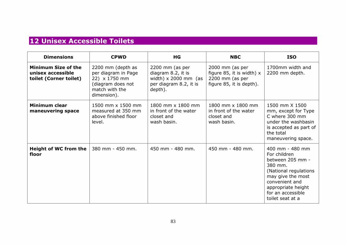
83
12 Unisex Accessible Toilets
Dimensions CPWD HG NBC ISO
Minimum Size of the unisex accessible
toilet (Corner toilet)
2200 mm (depth as per diagram in Page
22) x 1750 mm (diagram does not
match with the dimension).
2200 mm (as per diagram 8.2, it is
width) x 2000 mm (as per diagram 8.2, it is
depth).
2000 mm (as per figure 85, it is width) x
2200 mm (as per figure 85, it is depth).
1700mm width and 2200 mm depth.
Minimum clear maneuvering space
1500 mm x 1500 mm measured at 350 mm
above finished floor level.
1800 mm x 1800 mm in front of the water
closet and wash basin.
1800 mm x 1800 mm in front of the water
closet and wash basin.
1500 mm X 1500 mm, except for Type
C where 300 mm under the washbasin is accepted as part of
the total maneuvering space.
Height of WC from the floor
380 mm - 450 mm. 450 mm - 480 mm. 450 mm - 480 mm. 400 mm - 480 mm For children
between 205 mm - 380 mm.
(National regulations may give the most convenient and
appropriate height for an accessible
toilet seat at a

84
Dimensions CPWD HG NBC ISO
national level.)
Minimum distance from the edge of the
toilet seat to the rear wall
650 mm - 800 mm.
Distance from the adjacent wall to the centre line of the WC
As per diagram on page 22, it is 500 mm. (It is not mentioned in
the text).
460 mm to 480 mm. 460 mm to 480 mm (Fig. 85 is showing 500 mm).
450 mm. For children 305 mm to 380 mm.
Backrest Water closets shall be equipped with a back support such as a seat
lid and seats shall not be spring- actuated.
Have a suitable back support to reduce the chance of imbalance or
injury caused by leaning against
exposed valves or pipes.
Have a suitable back support to reduce the chance of imbalance or
injury caused by leaning against
exposed valves or pipes.
If a backrest is provided, the distance from the
seat to the backrest should range
between 500 mm and 550 mm.
Minimum floor space on the transfer side
adjacent to WC and in front
Not mentioned. It is given in the diagram in
Page 22 and there seems to be some error there.
1350 mm depth and 900 mm width, both in
front and on the transfer side, adjacent to the water
closet.
1350 mm depth and 900 mm width, both in
front and on the transfer side, adjacent to the water
closet.
Minimum free clearance beside the
toilet seat shall be 900 mm; 1200 mm is preferred for
lateral transfer and assistance.

85
Dimensions CPWD HG NBC ISO
Grab bar
Distance from WC A hinged type horizontal grab bar
should be installed adjacent to the water closet; at a distance of
320 mm from the centre-line of the WC.
A hinged type horizontal grab bar
should be installed adjacent to the water closet; at a distance of
320 mm from the centre-line of the WC.
On both sides of a toilet, a grab rail
(whether drop-down or fixed to the wall) shall be provided at a
distance between 300 mm to 350 mm
from the centre of the toilet.
Height of the grab bar The mounting height is not given in the text.
There are some dimensions mentioned in the diagram which is
not clear.
Be mounted at a height
between 200 mm and 250 mm from the water closet seat.
Be mounted at a height between 200
mm and 250 mm from the water closet seat.
Grab rails shall be provided at a height
of 200 mm to 300 mm above the toilet seat.
Vertical and
horizontal /L shaped grab bars
The two grab rails
constructed in one continuous piece is
acceptable.
One L-shape grab bar:
600 mm long horizontal and 700 mm
long vertical should be mounted on the side wall closest to
the water closet.
One L-shape grab bar,
600 mm long horizontal and 700 mm
long vertical shall be mounted on the side wall closest to the
water closet.
Vertical grab rail shall
exceed from the horizontal grab rail to
a height of 1700 mm above floor level. The grab rail shall extend
a distance of minimum 150 mm to
the front edge of the

86
Dimensions CPWD HG NBC ISO
toilet seat. The horizontal grab
rail shall be uninterrupted for its
full length.
Foldable/hinged grab
bars
There shall be one
folding grab rail on the wide side of the cubicle
adjacent to the water closet at a height between 725 mm to
750 mm above the finished floor level
when lowered from the wall.
A hinged type
horizontal grab bar should be installed
adjacent to the water closet between heights of 200 mm -
250 mm from the top of the water closet seat
and extending 100 to 150 mm beyond the front of the water
closet.
A hinged type
horizontal grab bar shall be installed
adjacent to the water closet, between heights of 200 mm -
250 mm from the top of the water closet
seat, and extending 100 to 150 mm beyond the front of the water
closet.
On the sides where a
lateral transfer is possible, a foldable
grab rail (drop-down support rail) shall be provided at a height
of 200 mm to 300 mm above the
toilet seat. The length of the foldable grab rail should
overlap the front edge of the toilet
seat in between 100 mm and 250 mm. The positioning of a
foldable grab rail should allow access
from a wheelchair when folded up. For children:
The grab rail height

87
Dimensions CPWD HG NBC ISO
for toilets for children should be between
510 mm to 635 mm.
Dimension of grab bar 35 mm - 500 mm in external diameter.
38 mm - 45 mm in diameter.
38 mm - 45 mm in diameter.
35 mm - 50 mm diameter.
Minimum grip space from the wall
30 mm. 50 mm. 50 mm. 40 mm.
Capacity to take static load
150 kg. 250 kg. 250 kg. Minimum 1 kN force from any direction,
with 1.7 kN as a recommendation.
Toilet door Door shall be installed with push-type or
lever-type handles and capable of being easily opened/closed by one
hand. Any door fastening shall be
capable of being released from the outside in the event of
an emergency. No coin box shall be affixed to
the door of the cubicle.
The toilet door should be either an outward
opening door or two-way opening door or a sliding type and should
provide a clear opening width of at least 900
mm. Be provided with a horizontal pull-bar, at
least 600 mm long, on the inside of the door,
located so that it is
The toilet door shall either be an outward
opening door or two way opening door or a sliding type and shall
provide a clear opening width of at least 900
mm. It shall be provided with a horizontal pull-bar, at
least 600 mm long, on the inside of the door,
located so that it is
The door shall have an unobstructed
width of at least 800 mm, with minimum 850 mm as a
recommended value, and it shall be easy
to open and close. The door should open outwards. If the door
opens inwards, there shall be a way to
open the door, or

88
Dimensions CPWD HG NBC ISO
The length of grab rail shall not be less than
600 mm. There shall be one grab rail fixed
on each of both the inner and outer surfaces of the cubicle
door; which shall not be less than 32 mm
and not more than 40 mm in external diameter.
130 mm from the hinged side of the door
and at a height of 1000 mm.
Be capable of being locked from the inside by a device that is
operable by one hand, activated by a force
not more than 22 N and which does not require fine finger
control, tight grasping, pinching or twisting of
the wrist.
130 mm from the hinged side of the door
and at a height of 1000 mm. It shall be
capable of being locked from the inside by a device that is operable
by one hand, activated by a force not more
than 20 N and which does not require fine finger control, tight
grasping, pinching or twisting of the wrist.
remove it, from the outside. There should
be no openings under or above the door. A
horizontal pull handle on outward opening doors shall be
provided at a height of 700 mm above the
floor.
Toilet Paper It can be seen in the
photo on Page 22 (below the grab rail)
but not in text or in the figure/diagram.
280 mm above the WC
(as per diagram on page 67).
280 mm above the WC
(as per diagram on page 162).
Dispensers for toilet
paper shall be reachable from the
toilet seat, either under the grab rail or on the side-wall of a
corner toilet at a height between 600
mm to 700 mm from the floor.
Towel, soap - Towel and soap Towel and soap Soap dispenser 800
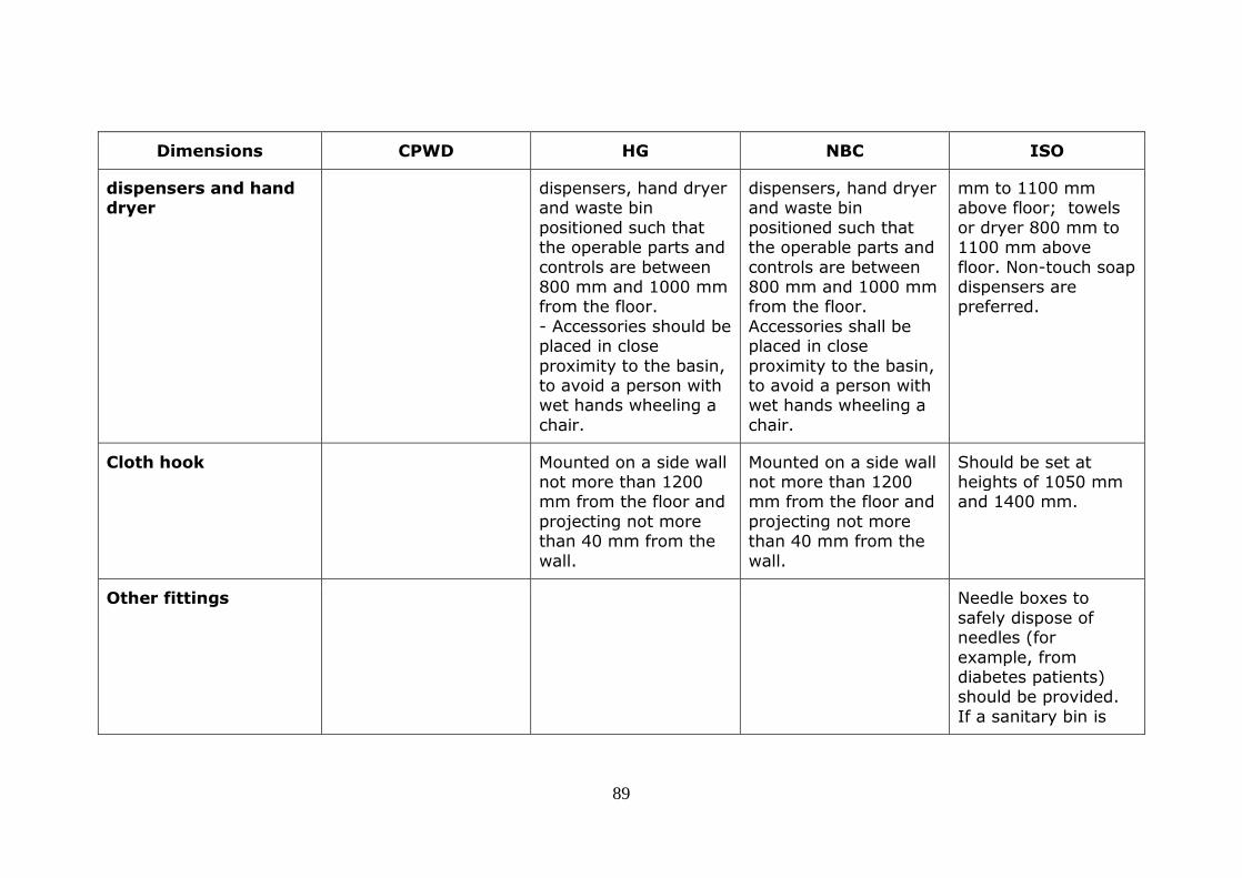
89
Dimensions CPWD HG NBC ISO
dispensers and hand dryer
dispensers, hand dryer and waste bin
positioned such that the operable parts and
controls are between 800 mm and 1000 mm from the floor.
- Accessories should be placed in close
proximity to the basin, to avoid a person with wet hands wheeling a
chair.
dispensers, hand dryer and waste bin
positioned such that the operable parts and
controls are between 800 mm and 1000 mm from the floor.
Accessories shall be placed in close
proximity to the basin, to avoid a person with wet hands wheeling a
chair.
mm to 1100 mm above floor; towels
or dryer 800 mm to 1100 mm above
floor. Non-touch soap dispensers are preferred.
Cloth hook Mounted on a side wall not more than 1200 mm from the floor and
projecting not more than 40 mm from the
wall.
Mounted on a side wall not more than 1200 mm from the floor and
projecting not more than 40 mm from the
wall.
Should be set at heights of 1050 mm and 1400 mm.
Other fittings Needle boxes to
safely dispose of needles (for
example, from diabetes patients) should be provided.
If a sanitary bin is

90
Dimensions CPWD HG NBC ISO
supplied, it should be reachable from the
toilet seat. Sanitary bins with non-touch
opening devices are preferred.
Emergency call bell An emergency call bell shall be equipped with
a weatherproof push button for activating the alarm. The push
button shall be installed below the
vertical grab rail inside the W.C. cubicle adjacent to the water
closet at a height between 600mm to
650mm above the finished floor level. A notice “Emergency
Call” in English, Hindi and Braille shall be
fitted next to the emergency Pushbutton. The alarm
shall be installed
An emergency alarm cum call switch should
be provided within easy reach on the wall near water closet at
two levels: at 300 mm and 900 mm from the
floor level to allow user to call for help in case of an emergency.
An emergency alarm cum call switch shall
be provided within easy reach on the wall near water closet at
two levels: at 300 mm and 900 mm from the
floor level to allow user to call for help in case of an emergency.
An assistance alarm, which can be reached
from changing or shower seats, from the WC and by a
person lying on the floor, shall be
provided in all accessible toilets and accessible sanitary
rooms. This alarm should be connected
to an emergency help point, or where a member of staff can
assist. Visual and audible
feedback should be provided to indicate that, when the alarm
has been operated,

91
Dimensions CPWD HG NBC ISO
outside the toilet or a buzzer
shall be fitted in the caretaker’s office.
the emergency assistance call has
been acknowledged and action has been
taken. It should take the form of a pull cord,
coloured red, with two red bangles of 50
mm diameter, one set at a height between 800 mm
and 1100 mm and the other set at 100
mm above floor level. A reset control shall be provided for use if
the alarm is activated by mistake. It shall
be reachable from a wheelchair and,
where relevant, from the WC, the tip-up seat in a shower or
changing facility, or the bed in an
accessible bedroom. The reset control

92
Dimensions CPWD HG NBC ISO
shall be easy to operate and located
with its bottom edge between 800 mm
and 1100 mm above floor level. For a corner toilet
room, the reset button should be
above the fixed horizontal grab rail beside the toilet
paper holder. The marking of the
reset control shall be both visible and tactile.
Emergency warning
alarm
- There should be a
visual emergency alarm in the toilet.
There shall be a visual
emergency alarm in the toilet.
A visual emergency
alarm shall be provided to alert people who are deaf
or hard of hearing in the event of an
emergency.
Flushing control Mounted on the wide
side of the cubicle at a
Should either be lever
type or automatic, and
Shall either be lever
type or automatic, and

93
Dimensions CPWD HG NBC ISO
height between 600 mm to 1050 mm
above the finished floor level and shall be
hand-operated or automatic. Hand operated controls shall
be capable of being operated with one
hand and shall not require tight grasping,
pinching or twisting of the wrist. The force
required shall not be greater than 22 N.
located on the transfer side of the
water closet. The flush control should not be
located more than 1000 mm from the floor.
located on the transfer side of the water
closet. The flush control shall not be
located more than 1000 mm from the floor.
Colour contrast There should be adequate colour and
tonal contrast between the fixtures, walls and the flooring. This is to
enable easy recognition by persons
with visual impairments.
Use of the same colour everywhere, for
example, white basins and white tiles, etc shall be avoided and
colour and tonal contrast should be
used to differentiate elements in the environment.
Fixtures and fittings in sanitary facilities
should visually contrast with the items and surface on
which they are positioned.

94
Dimensions CPWD HG NBC ISO
Lighting/ illumination The minimum illumination
measured at 800 mm above floor level shall
be 200 lux in the area of the washbasin.
Light switches should be fixed inside all
accessible toilet cubicles or the light should automatically
switch on when someone enters the
room. Timed light switches should not be installed or used.
Water supply/ hand-
held shower (health faucet)
An independent
water supply (hand-held shower) shall be provided next to the
toilet. An alternative such as a
combination bidet and rear side pan/built-in bidet can
be installed.

95
Observations and Recommendations
1. Types of Toilets: ISO has given three types of toilets - A, B and C. Type A allows both right and left lateral transfers.
Types B and C only allow one side transfer. Indian Guidelines (CPWD, HG and NBC) have given requirements only for toilets that allow one side transfer (‘Corner toilet’).
2. Dimensions of corner toilet: There are different dimensions for corner toilets in different Guidelines. CPWD provides
2200 mm x 1750 mm; HG gives 2200 mm x 2000 mm, NBC says 2000 mm x 2200 mm. ISO mentions 1700 mm width X 2200 mm depth. There seems to be an error in the diagram of HG (Figure 8.2), the measurements for depth
and width seems to have got interchanged. This should be corrected in the diagram. Moreover, the Indian Standards should specify in the text as to which is width and which is depth. CPWD should revise the dimensions based on NBC.
3. Maneuvering Space: CPWD should revise its specifications as per HG and NBC.
4. Height of WC from floor: NBC and HG are the same. ISO also has given dimensions for accessibility of toilet for children. CPWD should revise the dimensions as per NBC and HG. Indian Standards should add the specifications for
children. 5. Distance between adjacent wall and centre line of WC: CPWD gives the distance as 500 mm. This should be in
synchronised with NBC and HG which is 460-480 mm.
6. Backrest: CPWD, HG and NBC should mention the distance from the seat to the backrest as given in the ISO. 7. Minimum floor space adjacent to WC: CPWD should specify the space requirement in text and the diagram should
match the information given in text. The dimension should be the same as HG and NBC. 8. Vertical grab bar: As per ISO, the grab bar should end at 1700 mm from finished floor level. According to HG and
NBC the vertical grab bar should end at 700 mm from the horizontal grab bar (which would work out to 1350 mm from floor level). This should be increased to match the ISO Standard to enable better grip while standing.
9. The foldable grab bars: In CPWD, only mounting height is mentioned but not the extended part beyond the WC. This
should be incorporated as per NBC and HG. All Indian Standards should have specification for children. 10. Dimension of grab bars: In CPWD, external diameter has been given as 35 - 500 mm. (There is an error in the upper
limit.) This should be corrected as HG and NBC (38 -45 mm).

96
11. Minimum grip space from the wall: CPWD should revise the Standard from 30 mm to 50 mm to make it same as HG and NBC Standards.
12. Capacity to take static load: CPWD should revise the Standard from 150 kg to 250 kg to make it in line with HG and NBC Standards.
13. Toilet door: The mounting height of horizontal pull bar on the toilet door is given as 1000 mm in HG and NBC whereas the height given in ISO is 700 mm. The HG and NBC Guidelines seem high. Either it should be revised as per ISO or should be based on anthropometrics of Indian population with disability. The minimum force required for
opening the door in HG should be revised from 22 N to 20 N to make it in line with NBC. CPWD should add these points as given in HG and NBC.
14. Toilet paper: The specifications for placement of toilet paper dispenser are not given in text in Indian Guidelines though given in the diagrams. The specifications should also be given in the text as given in ISO.
15. Accessories: CPWD should add specifications for the placement of towel, cloth hook, hand dryer, soap dispenser, etc.
In ISO, it says non touch soap dispensers are preferred. This should be incorporated in Indian Standards as well. The point related needle box and sanitary bin given in ISO should be included in Indian Standards.
16. Emergency call bell: ISO has covered this aspect in detail. Indian Standards should adopt the specifications from the ISO.
17. Emergency warning alarm: CPWD should add this point.
18. Flushing Control: It should be standardised in Indian Guidelines. CPWD should revise the Standard for the placement of flushing control as per HG and NBC. HG and NBC should add the point related to force required to operate the
flush as per CPWD. 19. Colour contrast: CPWD should mention regarding colour contrast between fixtures, wall and flooring.
20. Lighting: Indian Standards should add minimum illumination levels as per given in ISO. 21. Health faucet: The Indian Standards should mention the provision for hand held shower (health faucet) next to WC.

97
13 Washbasin
Dimensions CPWD HG NBC ISO
Height of the washbasin
(rim/ top edge)
Not higher than 750 mm above
the finished floor level.
750 mm – 850 mm. 800 mm and 840 mm from the floor. Be
mounted such that the minimum distance
between the centreline of the fixture and the side wall is 460 mm.
750 mm to 850 mm from the floor.
The differences in stature of the population worldwide may require
lower or higher heights of washbasins. National regulations may give the most convenient and
appropriate height for washbasins at a national level.
Knee and
toe Space
A clearance of
550 mm shall be maintained from
the finished floor level to the bottom of the
apron.
Knee clearance: 200
mm. Foot clearance: 230
mm.
Knee space of at least
750 mm wide by 200 mm deep by 680 mm
high. Toe space of at least 750 mm wide by 230
mm deep by 230 mm high.
knee clearance: between 650 mm
and 700 mm high and 200 mm deep.
Toe clearance of at least 300 mm.
Maneuvering
space in front of washbasin
1800 mm x 1800 mm
in front.
900 mm wide by 1200
mm deep, of which a maximum of 480 mm
in depth may be under the wash basin.
In front of the washbasin, space
should allow for a frontal or oblique approach by a wheelchair.
Reach to the The front edge of the washbasin
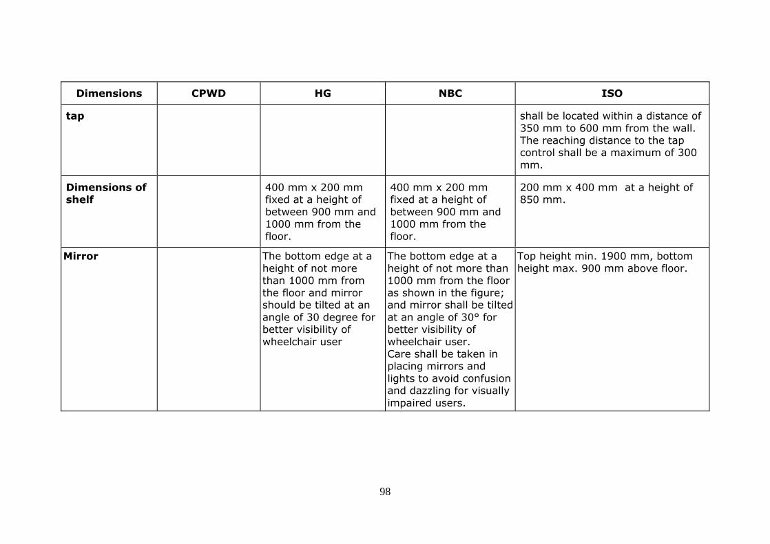
98
Dimensions CPWD HG NBC ISO
tap shall be located within a distance of
350 mm to 600 mm from the wall. The reaching distance to the tap control shall be a maximum of 300
mm.
Dimensions of shelf
400 mm x 200 mm fixed at a height of
between 900 mm and 1000 mm from the
floor.
400 mm x 200 mm fixed at a height of
between 900 mm and 1000 mm from the
floor.
200 mm x 400 mm at a height of 850 mm.
Mirror The bottom edge at a height of not more
than 1000 mm from the floor and mirror should be tilted at an
angle of 30 degree for better visibility of
wheelchair user
The bottom edge at a height of not more than
1000 mm from the floor as shown in the figure; and mirror shall be tilted
at an angle of 30° for better visibility of
wheelchair user. Care shall be taken in placing mirrors and
lights to avoid confusion and dazzling for visually
impaired users.
Top height min. 1900 mm, bottom height max. 900 mm above floor.

99
Observations and Recommendations
1. Height, knee and toe space of washbasin: HG and CPWD should be revised as per NBC. 2. Reach to the tap: This point should be added in all Indian Standards as per ISO. 3. Shelf and mirror: CPWD should include this point as other Standards.
4. Mirror: The mounting height of mirror should be as per ISO (i.e. bottom height 900 mm).

100
14 Taps
Dimensions CPWD HG NBC ISO
Type of taps / controls
Automatic or lever control
type without spring loading.
Tap shall not require tight grasping,
pinching or twisting of the
wrist.
Hand-operated or electronically controlled.
Hand-operated controls should:
- be operable by one hand; - require no tight grasping, pinching or twisting of the
wrist; have handles of lever type
(not self-closing) operable with a closed fist.
Hand-operated or electronically controlled
Hand-operated controls shall:
- Be operable by one hand; -Require no tight grasping, pinching or twisting of the
wrist Have handles of lever type
(not self-closing) operable with a closed fist.
Taps should be mixer, lever or sensor operated
to aid operation.
Force required Not greater than
22 N.
Less than 22 N to activate. Less than 20 N to activate.
Colour/tactile Colour-contrasted with the surrounding face plate panel
and the face plate should similarly contrast with the background wall on which it
is mounted.
Colour-contrasted with the surrounding face plate
panel and the face plate shall similarly contrast with the background wall on
which it is mounted.
Hot and cold water taps should be identifiable by both colour and tactile
markings.

101
Information Preferably be in relief (embossed letters/ symbols
accompanied with Braille information) for tactile
reading.
preferably be in relief (embossed letters/symbols
accompanied with Braille information) for tactile
reading.
Temperature A thermostat be installed to limit the temperature
of the hot water to a maximum of 40° C in order to prevent
scalding.
Observations and Recommendations
1. Force required to operate: There should be standardisation. 20 N as given in NBC and should be incorporated in all the
Indian Standards. 2. Colour and tactile indicators: CPWD and HG should include the points given in NBC. 3. Temperature: The point related to installing thermostat as given in ISO should be incorporated in all Indian Standards.

102
15 Urinals
Dimensions CPWD HG NBC ISO
Approach and maneuvering space
Not less than 800 mm wide x 1500 mm deep in front.
A clear floor space 760 mm by 1220 mm should be provided in front of urinals to allow
forward approach. Urinal shields (that do not extend
beyond the front edge of the urinal rim) may be provided with 735 mm clearance
between them.
A clear floor space 760 mm by 1220 mm shall be provided in front of urinals to allow forward
approach. Urinal shields (that do not extend beyond the front
edge of the urinal rim) may be provided with 735 mm clearance between them.
Clear floor area in front of the urinal of at least 750 mm
wide and 1200 mm deep.
Height of urinal (height
to the bottom rim)
Be wall hung urinal with a front rim not
higher than 400 mm.
Urinals shall be stall-type or wall-hung, with an elongated
rim at a maximum of 430 mm above the finish floor.
Urinals shall be stall-type or wall-hung, with an elongated
rim at a maximum of 430 mm above the finish floor.
When wall hung urinals are fitted in
the washroom, at least one at
following heights should be provided:
1. 600 mm-750
mm. 2. 380 mm and
3. 500 mm
Grab bars Have vertical grab rails of 600
mm length on both sides at a height of 1200 mm above the
finished floor level
Installed on each side and in the front of the urinal to
support ambulant persons with disabilities. The front bar is to provide chest support; the
sidebars are for the user to
installed on each side and in the front of the urinal to
support ambulant persons with disabilities (for example, crutch users). The front bar is to
provide chest support; the
Both Urinals (for wheelchair users
and standing persons) should be equipped with a
vertical grab rail.

103
Dimensions CPWD HG NBC ISO
for use by persons
with ambulant disabilities.
hold on to while standing. sidebars are for the user to
hold on to while standing.
Flush control Located not more than 1200
mm from the floor.
Located not more than 1200
mm from the floor.
Colour contrast There should be adequate colour and tonal contrast between the fixtures, walls and
the flooring. This is to enable easy recognition by persons
with visual impairments.
Use of the same colour everywhere, for example, white basins and white tiles,
etc shall be avoided and colour and tonal contrast should be
used to differentiate elements in the environment.
Urinals should contrast visually with the wall to
which they are attached.
Observations and Recommendations
1. Approach and maneuvering space: CPWD should revise the Standards based on HG and NBC.
2. Height of urinal (height to the bottom rim): ISO mentions installing urinals at 3 different heights. This should be incorporated in Indian Standards.
3. Grab bars: CPWD should add the point related to providing chest support from HG and NBC. 4. Flush control and colour contrast: These should be added in CPWD.

104
16 WC Compartments for Ambulant Disabled People
CPWD HG NBC ISO
- The dimensions are only given in the diagram and not in text.
Based on information in diagram some of the dimensions are given below: WC
height is 500 mm; horizontal grab rail 280 mm above WC; Vertical grab rail is 835 to 1295 mm above floor; pull rail on
door is 1070 mm above floor; 900 mm is width of the toilet.
The dimensions are only given in the diagram and not in text.
Based on information in diagram some of the dimensions are given below: WC
height is 500 mm; horizontal grab rail 280 mm above WC; Vertical grab rail is 835 to 1295 mm above floor; pull rail on
door is 1070 mm above floor; 900 mm is width of the toilet.
Toilet seat height, depth and distance to wall should
comply with 26.6 (i.e same as that for the unisex toilet,
i.e between 400 mm and 480 mm). Clear manoeuvring space in
front of the toilet should be minimum 900 mm 900 mm,
the door should open outwards, with a minimum. Unobstructed width of 800
mm. Grab rails on both sides of
toilet, independent water supply beside toilet seat, and floor
drain where necessary.
Observations and Recommendations
1. HG and NBC should give the specifications in the text also apart from diagram. CPWD should add this section.

105
17 Bathrooms and Showers
Dimensions CPWD HG NBC ISO
Size of shower compartments/cubicle - minimum internal
dimensions
Shower compartment : 1500 mm x 900
mm.
Shower cubicle: 2000 mm x 2200 mm. - A toilet cum shower
room: 2400 mm x 2500 mm
Shower cubicles: 2000 mm x 2200 mm. A toilet cum shower
room: 2400 mm x 2500 mm.
Wet showering area: 900 mm x 1300 mm, with a transfer area of
also 900 mm x 1300 mm.
Gradient The floor in the shower
recess shall have a gradient between 1:50
and 1:60 sloping to a floor drain. The area outside the shower
recess shall have a gradient between 1:70
and 1:80 draining towards the shower recess. The transition
into the shower recess shall be level without a
step down or a kerb.
Waste outlet The waste outlet should be centrally located and
be a round type outlet, not a channel type, to ensure the stability of

106
Dimensions CPWD HG NBC ISO
the shower chair.
Minimum clear floor
space
The minimum clear
floor space in front of the shower
entrance shall be 1500 mm x 900 mm with the 1500
mm dimension parallel to the
shower entrance.
The minimum clear floor
space in front of the shower entrance should
be 1350 mm x 900 mm with the 1350 mm dimension parallel to the
shower entrance. The floor of the shower
should be slip resistant.
The minimum clear floor
space in front of the shower entrance shall be
1350 mm x 900 mm with the 1350 mm dimension parallel to the shower
entrance. The floor of the shower shall be slip-
resistant even when wet.
A free space at least
1300 mm 900 mm shall be provided on the clear
side of the foldable seat, to allow access from a wheelchair, in addition
to the maneuvering space of 1500 mm. The
screening of a shower recess shall be either a curtain or a door system
that maintains the required circulation and
maneuvering space and does not interfere with the level entry.
Grab rails for shower compartments
Be L-shaped or two bars arranged in L-shaped
configuration and -Not be less than
750 mm by 900 mm in length; -Be installed at a
height between 700 mm and
800 mm from the
-Have one L-shaped bar or two grab bars in L-shaped configuration
between 700 mm and 800 mm from the
shower floor. Have one grab bar at least 750 mm long installed
vertically with another at least 900 mm long
mounted horizontally.
Have one L-shaped bar or two grab bars in L-shaped configuration
between 700 mm and 800 mm from the shower
floor as shown in the figure. Have one grab bar at
least 750 mm long installed vertically with
another at least 900 mm
Grab rails shall be set according to 26.7 (as for the unisex toilet) and
Figure 45 where a shower room diagram is
shown. As per the diagram it is not L shaped. There are
separate bars). The vertical grab rail holds
the flexible shower

107
Dimensions CPWD HG NBC ISO
shower floor; and
-Be capable of carrying a static load of 150 kg.
long mounted
horizontally.
head.
Position of shower seat Be installed at a height between 430 mm and 480
mm from the top of the seat to the
finished floor level.
The shower seat should be positioned such that the distance between
the centerline of the water closet and the
adjacent wall is 450 mm to 480 mm, and the distance between front
edge of the water closet and the rear wall is 650
mm. The top of the shower seat should be at a height of 450 - 480
mm from the floor.
The shower seat shall be positioned such that the distance between the
centerline of the water closet and the adjacent
wall is 450 mm to 480 mm, and the distance between front edge of
the water closet and the rear wall is 650 mm. The
top of the shower seat shall be at a height of 450 - 480 mm
from the floor.
When folded down, have its top surface set between 400 mm and
480 mm above floor level and spaced a
maximum of 40 mm from the rear wall.
Size of shower seat Size shall not be less than 550 mm
in width and 400 mm in depth.
Have a minimum dimension of 400 mm
wide extending the full depth of the cubicle,
less a space required for the shower curtain.
Have a minimum dimension of 400 mm
wide extending the full depth of the cubicle, less
a space required for the shower curtain.
Minimum size of shower seat shall be 450 mm x
450 mm.
Other features of
shower seat
Have a rounded
edge and be self-draining. Be installed on the
- A wall mounted
shower seat, preferably fold up kind. - Be self-draining, non-
-A wall mounted shower
seat, preferably fold up kind. -Be self-draining, non-
The foldable seat shall
have the following features: Self-draining; slip-

108
Dimensions CPWD HG NBC ISO
wall next to the
taps and controls.
slip and with rounded
edge; - Be on the wall nearest to the controls;
- Enclosures for the shower cubicle shall not
obstruct transfer from wheelchair onto shower seat.
slip and with rounded
edge; - Be on the wall nearest to the controls;.
-Enclosures for the shower cubicle shall not
obstruct transfer from wheelchair onto shower seat.
resistant and stable;
foldable in an upwards direction; when folded, it shall not present a
hazard and the grab rail shall be accessible from
the foldable seat. The foldable seat should have the following
features: rounded front corners
(radius 10 mm to 15 mm), rounded top edges (minimum radius
of 2 mm to 3 mm). The foldable seat should
preferably be height adjustable.
Shower heads and
controls
Be of the hand-
held type. Be provided with a
hose not less than 1500 mm in
length. Be provided with a wall mounting
bracket to allow
The adjustable and
detachable shower head (telephone shower/ hand-held shower), with
a minimally 1500 mm long hose, should be
installed between 800 mm and 1200 mm from the floor.
All shower controls
The adjustable and
detachable shower head (telephone shower/hand-held shower), with a
minimally 1500 mm long hose, shall be installed
between 800 mm and 1200 mm from the floor. All shower controls shall
be at a distance of 500
A hand held detachable
shower head shall be provided with a flexible hose of minimum length
1200 mm, and it shall be able to reach within
100 mm of the shower floor.

109
Dimensions CPWD HG NBC ISO
use in a fixed
position. Where shower heads are mounted
on a vertical bar, the
bar shall have a minimum length of 500 mm with the
lower end not less than 450 mm
above the finished floor level.
should be at a distance
of 500 mm from the rear wall. -Shower controls should
be installed between 750 mm to 1000 mm
from the floor.
mm from the rear wall.
Shower controls shall be installed between 750 mm to 1000 mm from
the floor.
Shelf A shelf should be
provided for toiletries between 400-800 mm.
A shelf shall be provided
for toiletries between 400-800 mm.
Observations and Recommendations
1. Size of shower compartments: CPWD should revise the Standards based on HG and NBC.
2. Surface and gradient: ISO mentions that the transition into the shower recess shall be level without a step down or a kerb and it also specifies the gradient. These should be added in the Indian Standards.
3. Waste outlet: The point related waste outlet should be included in Indian Standards. 4. Grab rails for shower compartments: CPWD should incorporate points related to dimensions of grab bars from HG and
NBC. HG and NBC should add the point related to the strength of grab bars.

110
5. Position of shower seat: CPWD should make the specifications same as HG and NBC. ISO has given that it should be placed 40 mm from the rear wall, which should be incorporated in the Indian Standards. Also, the term water closet
should be replaced with shower seat. 6. Size of shower seat: HG and NBC mention that it should, be 400 mm wide extending the full depth of the cubicle.
However, the diagram is showing L- shaped shower seat (Fig 95 of NBC). This should be specified with exact dimensions in the text and diagram. The detailing of shower seat like the “rounded front corners (radius 10 mm to 15 mm), rounded top edges (minimum radius of 2 mm to 3 mm). The foldable seat should preferably be height
adjustable.” These should be added in Indian Standards. 7. Shower controls: CPWD should incorporate points from HG and NBC.

111
18 Emergency Evacuation Needs
Dimensions CPWD HG NBC ISO
General (warning
systems)
Available technologies enable warnings to be communicated
simultaneously by sounder, light strobe, voice message and individual tactile sensation by vibration.
Non auditory alarms
Non – auditory alarms (visual or sensory) to alert persons with hearing impairments
should be installed at visible locations in all areas that the
building users may visit (including toilet areas, storerooms etc.). Non-auditory
alarms include flashing beacons.
Non-auditory alarms (visual or sensory) that include flashing beacons, to alert persons with
hearing impairments shall be installed at visible locations in
all areas that the building users may visit (including toilet areas, storerooms, etc).
Visual strobe alarms should be provided, particularly in isolated areas (bathrooms, meeting rooms)
and noisy areas. Room layouts, lighting levels and furniture
arrangements shall be considered to ensure that these alarms are visible. A strobe frequency of 0.5 Hz – 4 Hz
minimizes the risk of triggering a reaction from a person with epilepsy.
Care should be taken to ensure that overlapping strobes do not combine to result in a higher frequency of
flashing. Vibrating devices such as pagers or mobile phones can be
integrated with alarm systems to provide an individual alarm.
A larger number of strobes/beacons with low output should be specified –

112
Dimensions CPWD HG NBC ISO
never a small number of strobes/beacons with high output as
these produce glare causing confusion and disorientation among
building users. Adapt light output of strobes/beacons to suit the use of particular areas.
For light strobes/beacons, a slow rate of flash should be ensured (e.g.
once every two seconds) in order to avoid epileptic seizures. Most importantly, the flash of one
strobe/beacon should be synchronized with the flashes of all
other light strobes/beacons in view.
Auditory warning
systems
Audible alarms with ‘Voice Instructions’ should be installed
that can help guide them to the nearest emergency exit. As an alternative to the
pre-recorded messages, these alarms may be connected to
central control room for on-the spot broadcasts.
Audible alarms with ‘voice instructions’ shall be installed
that may help guide them to the nearest emergency exit. As an alternative to the pre-
recorded messages, these alarms shall be connected to
the central control room for on the-spot broadcasts.
Acoustic warning systems: A larger number of sounders
between 85 dB to 95 dB with low output should be specified – never a small number of sounders with high
output which only leads to confusion and disorientation among building
users. Vocal messages should be short and should contain appropriate warning information which is easily
assimilated. The speaker should be distinct and easy to understand. In
today's multi-cultural built

113
Dimensions CPWD HG NBC ISO
environment, messages should be given in at least two different
languages.
Alarm panels
Fire alarm boxes, emergency call buttons and lighted panels
should be installed between heights of 800 mm and 1000
mm from the finished floor surface. These should be adequately contrasted in colour
and tone from the background wall and should be labelled with
raised letters and also in Braille.
Fire alarm boxes, emergency call buttons and
lighted panels should be installed between heights of
800 mm and 1000 mm from the finished floor surface. These shall be adequately
contrasted in colour and tone from the background wall and
shall be labelled with raised letters and also in Braille.
Lifts
All lifts (elevators) in new buildings
should be capable of being used for people evacuation in a fire situation; lifts in existing buildings,
when being replaced or undergoing a major overhaul, should be made
capable of being used for people evacuation in a fire situation.
Alarm
panels
Fire alarm boxes, emergency
call buttons and lighted panels should be installed between heights of 800 mm and 1000
mm from the finished floor
Fire alarm boxes,
emergency call buttons and lighted panels should be installed between heights of
800 mm and 1000 mm from

114
Dimensions CPWD HG NBC ISO
surface. These should be adequately contrasted in colour
and tone from the background wall and should be labelled with
raised letters and also in Braille.
the finished floor surface. These shall
be adequately contrasted in colour and tone from the
background wall and shall be labelled with raised letters and also in Braille.
Emergency evacuation routes
In buildings or facilities, or portions of buildings or facilities, required to be
accessible, accessible means of egress shall be provided in the
same number as required for exits by local building/fire safety regulations (National
Disability Authority, 1998). Designating evacuation routes
shall be at least 1500 mm wide, to ensure a wheelchair user and an able bodied person
are able to pass each other along the route. The route
should be free of any steps or sudden changes in level and should be kept free from
obstacles such as bins and flower pots etc. An exit
stairway to be considered part
In buildings or facilities, or portions of buildings or facilities to which these requirements
apply, accessible means of egress shall be provided in the
same number as required for exits by local building/ fire safety regulations. These shall
meet the following requirements:
- Designated evacuation routes shall be minimum 1500 mm wide, to ensure that a
wheelchair user and a non-disabled user are able to pass
each other along the route. The route shall be free of any steps or sudden level changes and
shall be kept free from obstacles such as bins and
flower pots etc, all the time.
It is essential that movement to and from each area of rescue assistance does not encroach on the evacuation
travel space of the staircase. Door leaves should also not open into or
over this evacuation space. Note: There may be competition between staircase evacuees and
people using the area of rescue assistance (and reduced ability to
achieve objectives) if the evacuation travel space of the staircase overlaps the space used for movement to and
from an area of rescue assistance. Fire evacuation routes, including all
areas of rescue assistance, shall be kept clear at all times. An area of rescue assistance should be of
sufficient size to cope with expected needs in a fire emergency. For
example, if there are only two

115
Dimensions CPWD HG NBC ISO
of an accessible means of egress shall have a minimum
clear width of 1500 mm between handrails and shall
either incorporate an area of refuge within an enlarged floor-level landing or a
horizontal exit. Orientation and direction signs should be
installed frequently along the evacuation route and these should preferably be internally
illuminated. Whilst the emergency lighting
provided by traditional overhead emergency lighting luminaries, conforming to the
Indian Standard IS: 9583-1981:
Exit signs shall be in accordance with IS: 4878-
1968. Exit signage should also be available in tactile format in the evacuation route.
Note: Fireproof doors along circulation paths that are not
exclusively egress routes generally require a force greater than 25 N to operate,
- An exit stairway considered a part of an accessible means of
egress shall have a minimum clear width of 1500 mm
between handrails and shall either incorporate an area of refuge with an enlarged floor-
level landing or a horizontal exit.
- Orientation and direction signs shall be installed frequently along the evacuation
route and these shall preferably be internally illuminated.
- The emergency lighting provided by traditional overhead emergency lighting
luminaries, conforming to the Indian Standard IS: 9583-
1981: - Exit signs shall also comply with the good practice.
Exit signage shall also be available in tactile format in the evacuation route.
NOTE ─ Fireproof doors along circulation paths that are not
exclusively egress routes generally require a force greater than 20 N to operate,
evacuation staircases on a floor in a building (on opposite sides), each
area of rescue assistance should be designed to cater for the expected
needs of the full floor.

116
Dimensions CPWD HG NBC ISO
rendering several disabled people dependent on others to
negotiate these doors. Consider holding the doors open with
magnetic catches or ‘floor springs’ that are connected with the fire alarm system.
rendering several disabled people dependent on others to
negotiate these doors. Doors which may be held open
with magnetic catches or ‘floor springs’ that are connected with the fire alarm system,
may be considered.
Provision of refuge areas
Accessible refuge areas shall meet the following
requirements: -Where a required exit from an
occupiable level above or below a level of accessible exit discharge is not
accessible, refuge areas shall be provided on
each such level (in a number equal to that of inaccessible required exits).
-Every required area of refuge is to be accessible from the
space it serves by an accessible egress route. -Every area of refuge shall
have direct access to an exit stairway.
-Each area of refuge must be
Accessible refuge areas shall meet the following
requirements: - Where a required exit from an
occupiable level above or below a level of accessible exit discharge is not
accessible, refuge areas shall be provided on
each such level (in a number equal to that of inaccessible required exits).
- Every required area of refuge shall be accessible from the
space it serves by an accessible egress route. - Every area of refuge shall
have direct access to an exit stairway.
- Each area of refuge shall be
An area of rescue assistance in a building should: be provided on
every floor of a building, adjoin every evacuation staircase, include
space for persons in wheelchairs, have good lighting and be clearly indicated with good
signage, be fitted with an accessible and reliable independent
communication system fitted at a height of 800 mm to 1100 mm above floor level, facilitating direct
contact with a person in the designated control room for the
building, be of sufficient size for the storage of an evacuation chair and a manual fire alarm call point, a fire
evacuation supply kit containing, for example, smoke hoods, suitable
gloves to protect a person's hands

117
Dimensions CPWD HG NBC ISO
separated from the remainder of the story by a smoke barrier
having minimally one hour fire resistance rating. Each area of
refuge is to be designed to minimize the intrusion of smoke.
-The size of the refuge to provide at least two accessible
areas each being not less 750 mm by 1200 mm. The area of rescue assistance shall not
encroach on any required exit width. The total number of such
areas per story shall be not less than one for every 200 persons of calculated occupant load
served by the area of rescue assistance.
-All stairs next to the refuge should have a clear width of
1500 mm between the handrails. -A method of two-way
communication, with both visible and audible signals,
shall be provided between each area of rescue assistance and the primary
separated from the remainder of the storey by a smoke
barrier having minimally one hour fire resistance rating.
Each area of refuge shall be designed to minimize the intrusion of smoke.
- The size of the refuge shall provide at least two accessible
areas each being not less than 750 mm by 1200 mm. The area of rescue
assistance shall not encroach on any required exit
width. The total number of such areas per storey shall be not less than
one for every 200 persons of calculated
occupant load served by the area of rescue assistance.
- All stairs next to the refuge shall have a clear width of 1 500 mm between the
handrails. - A method of two-way
communication, with both visible and audible signals, shall be provided between each
from debris when pushing his/her manual wheelchair, etc.
Note: Many commercially available smoke hoods are advertised to
provide protection from more fire effects than they actually do provide.

118
Dimensions CPWD HG NBC ISO
entry. area of rescue assistance and the primary
entry.
Signage
Each area of rescue assistance shall be identified by a sign,
which states "REFUGE AREA" and displays the international
symbol of accessibility. The sign should be illuminated when exit sign illumination is
required. Signage should also be
installed at all inaccessible exits and where otherwise necessary to clearly indicate
the direction to areas of rescue assistance.
In each area of rescue assistance, instructions on the use of the area under
emergency conditions shall be posted adjoining the two-way
communication.
Each area of rescue assistance shall be identified by a sign
which reads “REFUGE AREA” and displays the international
symbol of accessibility. The signs shall be illuminated when exit sign illumination is
required. Signage shall also be installed at all
inaccessible exits and where otherwise necessary to clearly indicate the direction to areas
of rescue assistance. In each area of rescue assistance,
instructions on the use of the area under emergency conditions shall be posted
adjoining the two-way communication.
Be marked with good signage. Communication systems at areas of
rescue assistance should provide visual feedback to people with
hearing impairments that their location has been noted. The control point for the communication systems
should be of a robust design to avoid risk of confusion about the location
of building users. Where a signal board is used, this should be engraved or otherwise permanently
marked to identify the particular building location, and should not rely
on sticky labels or translation tables.
Assisted fire evacuation
strategy
A fire defence plan elaborates the particular fire engineering
strategy which has been developed for a specific building. It is usually in hard
A fire engineering strategy is needed that will indicate what is required so
that every occupant can be protected from fire, from their location when fire begins through

119
Dimensions CPWD HG NBC ISO
copy and/or electronic format and comprises fire engineering
drawings, descriptive text, fire safety related product/system
information, with supporting calculations and fire test data. The fire defence plan shall
demonstrate a proper consideration for the fire
safety, protection and evacuation of the users of the building (occupants, visitors
and other users) and who may or may not have a health
condition or impairment. This may be a requirement of national legislation.
their evacuation and at their location after evacuation, in accordance with
accepted principles of fire evacuation for all. Included in these principles
are that the features of the building should support successful evacuation and every occupant, whatever his or
her abilities, should be able to evacuate independently to the
maximum degree possible. However, independent evacuation may not be possible for all occupants,
particularly in the case of existing buildings. For those occupants who
need assisted evacuation, there should be a strategy for the provision of assisted evacuation, and
there may need to be areas of rescue assistance.
Evacuation
chairs
Evacuation chairs should be capable
of: being safely and easily operated; carrying people of high
weight (up to 150 kg); going up and down staircases; travelling long distances horizontally and externally.

120
Observations and Recommendations
1. Indian Standards should mention all the available technologies, as in ISO (example, individual tactile sensation by vibration).
2. Non auditory and auditory alarms: It is well detailed in ISO and Indian Standards should incorporate them.
3. Alarm panel: It should be included in CPWD. 4. Lifts: ISO mentions that all new lifts should be used for evacuation of people with disabilities. It should be
incorporated in all Indian Standards. 5. Emergency Evacuation Routes: This has been detailed in NBC and HG. HG uses the term, ‘able bodied’. It should be
changed to ‘’non disabled people’. CPWD should add this point.
6. Force required to open fire door: HG mentions 25 N and NBC 20 N as the force required to open the fire door. HG should change it to 20 N and CPWD should include this point.
7. Refuge area: ISO has a few additional points like providing sufficient size for the storage of an evacuation chair, manual fire alarm call point, a fire evacuation supply kit containing, for example, smoke hoods, etc. Thses should be added in Indian Standards.
8. Assisted fire evacuation strategy: ISO mentions that a strategy should be prepared for occupants who need assisted evacuation. This is mentioned in NBC as a fire defence plan. It should be incorporated in HG and CPWD as well.
9. Signage: ISO mentions, “Where a signal board is used, this should be engraved or otherwise permanently marked to identify the particular building location, and should not rely on sticky labels or translation tables.” This should be incorporated in HG and NBC. CPWD needs to include the description on signage as in HG and NBC.
10. Evacuation chairs: This point needs to be included in all Indian Standards.
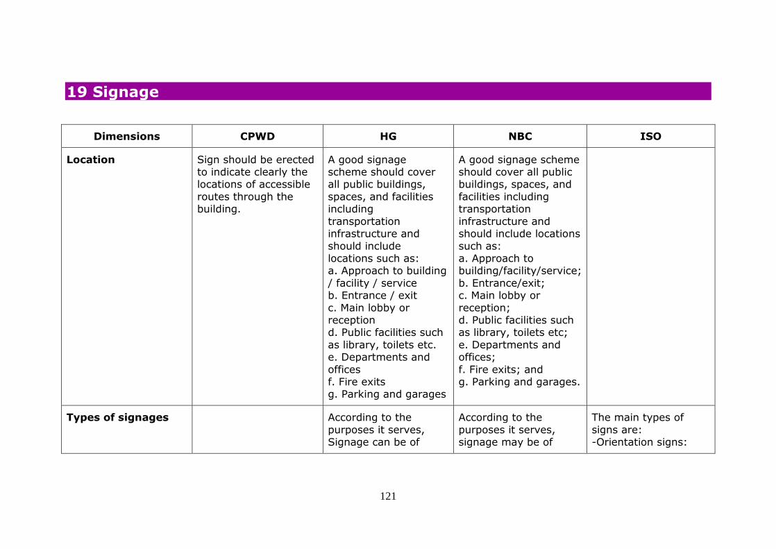
121
19 Signage
Dimensions CPWD HG NBC ISO
Location Sign should be erected to indicate clearly the locations of accessible
routes through the building.
A good signage scheme should cover all public buildings,
spaces, and facilities including
transportation infrastructure and
should include locations such as: a. Approach to building
/ facility / service b. Entrance / exit
c. Main lobby or reception d. Public facilities such
as library, toilets etc. e. Departments and
offices f. Fire exits g. Parking and garages
A good signage scheme should cover all public buildings, spaces, and
facilities including transportation
infrastructure and should include locations
such as: a. Approach to building/facility/service;
b. Entrance/exit; c. Main lobby or
reception; d. Public facilities such as library, toilets etc;
e. Departments and offices;
f. Fire exits; and g. Parking and garages.
Types of signages According to the
purposes it serves, Signage can be of
According to the
purposes it serves, signage may be of
The main types of
signs are: -Orientation signs:

122
Dimensions CPWD HG NBC ISO
following types: a) Directional
b) Information c) Identification
d) Instructive e) Health and Safety
following types: a) Directional;
b) Information; c) Identification;
d) Instructive; and e) Health and Safety.
sketches, plans, models, etc.
-Directional signs: directional information
from point A to B. -Functional signs: explanatory
information. -Informative signs:
purely informative, for example a name. -Signs for emergency
exits
Placement / height of the signs
Braille and tactile sign shall be installed on adjacent wall or door
of public toilet to indicate whether the
toilet is for male, female or unisex. The sign shall be
placed at 900 mm to 1500 mm above the
finished floor level. If there is no door, the sign shall be provided
on the wall in front of
Wall-mounted signs/ timetables/maps or diagrams, should be
centered around 1400 mm from the ground,
with the bottom edge not less than 900 mm from the finished floor
level and the top edge up to 1800 mm from
the finished floor level. Duplicating detailed signs and instructions,
especially safety
Wall-mounted signs; timetables, maps or diagrams, should be
centered around 1400 mm from the ground,
with the bottom edge not less than 900 mm from the finished floor
level and the top edge up to 1800 mm from
the finished floor level. Position projecting or ceiling suspended signs
above head height at
Directional and functional signs should be located below 1600
mm. Signs should be placed between 1200
mm and 1600 mm from the floor or ground surface.
Where it is likely that the sign may be
obstructed, as in a crowded situation, the signs shall be placed
at a height of at least

123
Dimensions CPWD HG NBC ISO
the toilets. A Braille and tactile fire exit
map shall be provided directly above the call
button of the accessible lift in the lobby of the accessible
lift in a building if a fire exit map for the use of
the public is provided. The map shall be placed at 800 mm to
1200 mm above the finished floor level.
notices, should be located at high and low
levels, i.e. at 1600 to 1700mm and at 1000
to 1100mm. Position projecting or ceiling suspended signs
above head height at 2300 mm from floor
level. Top of building directory signage,
building direction signage and bulletin
board signs should be 1800 mm from the finished floor level.
Room number and identification signage
to be at 1400 mm from the finished floor level
to bottom of the sign, and 50 mm from the door frame In case of
tile wall, the closest horizontal joint should
be used.
2300 mm from floor level.
Top of building directory signage,
building direction signage and bulletin board signs shall be
1800 mm from the finished floor level.
Room number and identification signage to be at 1400 mm from
the finished floor level to bottom of the signs,
and 50 mm from the door frame. In case of the tile wall the closest
horizontal joint should be used.
Detailed signs and instructions, especially
safety notices should be located at both high and low levels, that is,
at 1600 - 1700 mm and at 1000 -1100 mm.
2100 mm above the floor. The same
requirement applies to signs fixed to the
ceiling or projecting from walls. In that case, there should be
two signs; one that can be seen from a
distance above other people's heads, one as a complement at the
height recommended above. Where there is
sufficient space, door signs shall be located on the latch side of the
door within 50 mm to 100 mm of the
architrave.

124
Dimensions CPWD HG NBC ISO
Size of signage The height of signs shall be not less than
the following :
- 60 mm for doors -110 mm for corridors - 200 mm for external
use.
Size of signage for various viewing
distances shall be as below: Upto 7m : 60 x
60 mm; 7 - 8 m: 100 x 100 mm; exceeding 8 m: 200 x 200 mm to
450 x 450 mm Size of letters in signage for
various viewing distances shall be as below: 2-3 m : 15
mm; 6 m: 20 mm; 8 m: 25 mm; 12 m: 40
mm; 15m: 50 mm; 25 mm: 80 mm; 35m: 100 mm; 40 m: 130
mm; More than 40 m: 150 mm.
Size of signage for various viewing
distances shall be as below: Upto 7 m: 60 x
60 mm; 7 - 8 m: 100 x 100 mm; exceeding 8 m: 200 x 200 mm to
450 x 450 mm Size of letters in signage for
various viewing distances shall be as below: 2-3 m : 15 mm;
6 m: 20 mm; 8 m: 25 mm; 12 m: 40 mm; 15
m: 50 mm; 25 mm: 80 mm; 35m: 100 mm; 40 m: 130 mm; More than
40 m: 150 mm.
The letter height depends on the
reading distance. A letter height between
20 mm and 30 mm for each meter of viewing distance is preferred.
The letter height should not be less
than 15 mm.
Character, content and layout, signage
typeface and style
Lettering should be plain and legible, e.g.
Arial (medium) using lower case letters
except for initial capitals. Corners of sign should be
rounded. Sign should
Sign typefaces must be standard, legible and
clearly discernible. Only Sans serif family
of fonts are recommended such as Arial, Helvetica
Medium, Futura etc.
Sign typefaces must be standard, legible and
clearly discernible. Only Sans serif family of
fonts are recommended such as Arial, Helvetica Medium, Futura etc.
Usage of too many type
It is recommended that messages of
single words or groups of words begin with an
upper case letter and continue with lower case letters (sentence
case).

125
Dimensions CPWD HG NBC ISO
be in raised characters. The system of sign
used should be clear and consistent.
Usage of too many type sizes on any one
sign should be avoided.
- Should be mix of upper and lower case -Should be Left
justified -Should be Tactile
embossed with Braille -Minimal use of bold -Consistent font stem
widths -Avoid italics, script
text, condensed text, light stems.
sizes on any one sign should be avoided.
-Should be mix of upper and lower case
-Should be Left justified -Should be Tactile embossed with Braille
-Minimal use of bold -Consistent font stem
widths -Avoid italics, script text, condensed text,
light stems.
The words should not be placed too close
together. Adequate height spacing should
separate the lines. Lines of text should be ranged from a vertical
line (unjustified). Signs with a single
word may be centre justified. The fonts should be
easy to read. The font style should be a sans
serif font similar to Helvetica or Arial medium.
Signs should be readily
understandable.
Colour and luminous
contrast
Luminous contrast of
not less than 70% should be provided to
differentiate the international symbol of accessibility from the
background, either
The colour
combinations red/green and
yellow/blue should not be used in order to avoid confusing
persons
The colour
combinations red/green and yellow/blue should
not be used in order to avoid confusing persons who are colour blind.
Safety signs use
Minimum difference in
LRV for small targets, such as signs and
inscriptions, to signboards, should be 60 points.
Signboards should

126
Dimensions CPWD HG NBC ISO
light-on-dark or dark-onlight. The commonly
employed colours are white for the
wheelchair figure and blue for the background.
who are colour blind. Safety signs use
primarily red, yellow and green as
information colours. For other signs it is preferable to use Blue
and White Colours. - Text should contrast
with sign background -Sign should contrast with environment
- Light levels (measured in Lux)
-70% contrast between wall and sign panel -Avoid shades of
colours -Avoid using same
colours as safety signs -Maximum 5 colours
Non-reflective surface. Table 6-1 gives Typical Schedule of Colour
Contrast for Signs.
primarily red, yellow and green as
information colours. For other signs it is
preferable to use Blue and White Colours. - Text should contrast
with sign background - Sign should contrast
with environment - Light levels (measured in Lux)
-70% contrast between wall and sign panel
-Avoid shades of colours -Avoid using same
colours as safety signs -Maximum 5 colours
on-reflective surface. Table B-11.5.1.3 gives
Typical Schedule of Colour Contrast for Signs.
have a minimum difference in LRV from
the background of 30 points.
Red-green combination should be avoided. Difficulties in
perception can also appear when using the
colours green, olive green, yellow, orange, pink and red. Refer to
the contrast section in B.7.
Line spacing and
character proportion
- The spacing between
lines should be 50% of
The spacing between
lines shall be 50
Adequate height
spacing should

127
Dimensions CPWD HG NBC ISO
and height the line height. A style should be chosen
because based on a character width-to-
height ratio within 3:5 and 1:1 and the stroke width-to-height ratio
between 1:5 and 1:10. It should be consistent
for each sign.
percent of the line height. A style shall be
chosen based on a character width-to-
height ratio within 3:5 and 1:1 and the stroke width-to-height ratio
between 1:5 and 1:10. It shall be consistent
for each sign.
separate the lines. Lines of text should be
ranged from a vertical line (unjustified).
Pictograms Signs should be clear
and easy to read and understand in order to
assist persons with intellectual, cognitive and sensory
disabilities.
Ideally any signage
should incorporate a combination of
lettering and symbols.
Ideally any signage
should incorporate a combination of lettering
and symbols.
Universally accepted
pictograms should be used. See ISO 7000,
ISO 7001, ISO 7010, ISO 16069 and ISO 28564-1.
Braille Specification of Braille cells is shown in Figure 31.
As per the table given, Dot Spacing: 2.5 mm;
character spacing 6.5 mm; Dot height 0.5 mm; line spacing 10.0
mm; Dot base
Figure 6-21 gives Braille specifications. Not mentioned in text.
Fig. 114 gives Braille Specification for Signage. Not
mentioned in text.
Where an arrow is used in the tactile sign, a small arrow
shall be provided for Braille readers.
On signs with multiple lines of text and characters, a semi-
circular Braille locator

128
Dimensions CPWD HG NBC ISO
diameter 1.5 mm. on the left margin shall be horizontally
aligned with the first line of Braille text.
Braille should be raised, domed and comfortable to touch.
It should be located 8 mm below the bottom
line of the text and be left justified.
Tactile lettering Sign should be in raised characters
Embossed letters, raised pictograms and
raised arrows are tactile features that can be incorporated
into signs, which can be particularly helpful
to persons with visual impairment.
Embossed letters, raised pictograms and
raised arrows are tactile features that may be incorporated
into signs, which may be particularly helpful
to persons with visual impairments.
Raised tactile letters and graphical symbols,
height 15 mm to 55 mm, minimum relief 0,8 mm (1 mm to 1,5
mm relief is preferred).
Maps and models If a floor plan for the use of the public is
provided, Braille and tactile floor plan showing the main
entrance, public toilet
A tactile map or model is a useful way of
providing information to visually impaired people and people with
hearing impairments
A tactile map or model is a useful way of
providing information to visually impaired people and people with
hearing impairments
Only essential information should be
included on a tactile map or floor plan. Tactile maps shall be
angled between 20° to

129
Dimensions CPWD HG NBC ISO
and major common facilities shall be
provided in a place in that building which is
prominent to persons with visual impairment.
who wish to navigate around a building.
who wish to navigate around a building.
30° from the horizontal for ease of
reading, and the bottom edge shall be
at a minimum height of 900 mm. The map should have a level of
illumination between 350 lux and 450 lux,
without glare. The key should be located at the bottom of the map
and left justified. The use of a recessed
Braille locator on the left hand side should assist in locating the
legend. The map shall be
orientated with the building.
Lighting/ signage illumination
- Signs should be well and evenly lit with
uniform lighting over the surface of the sign of between 100 and
300 lux. Minimum
Signs shall have a matt finish, not a shiny or
glossy one, and shall be well and evenly lit with uniform lighting over
the surface of the sign
Signs should be glare free when mounted.
This depends on how the sign is placed, the material and the
illumination. The

130
Dimensions CPWD HG NBC ISO
acceptable level of lighting for directional
signage, maps and text panel is 200 lux.
of between 100 and 300 lux. Minimum
acceptable level of lighting for directional
signage, maps and text panel is 200 lux.
background, graphical symbols, logos and
other features shall be of a matte or low
sheen finish. Signs can be luminescent or artificially lit. The map
should have a level of illumination between
350 lux and 450 lux, without glare.
Graphical symbols - The International Symbol of Accessibility
must be displayed at all accessible entrances. Similar
guidelines refer to elevators,
evacuation and refuge areas, restrooms and bathing facilities.
Symbols of accessibility are also
required to identify volume control telephones, text
telephones, and
The international Symbol of Accessibility
shall be displayed at all accessible entrances and accessible facilities.
If an entrance is not accessible, directions to
an accessible route, including the symbol, shall be
provided. Similar guidelines refer to
elevator, evacuation and refuge areas, restrooms and bathing
facilities. Symbols of
ISO/TC 145 Graphical symbols has
developed the following standards for graphical symbols:
ISO 7000, ISO 7001 and ISO 7010. These
include graphical symbols relevant to accessibility and a
selection is shown below (see Figures 66,
67 and 71). Pages 105 and 106 give a list of accessible facilities for
which they can be

131
Dimensions CPWD HG NBC ISO
assistive listening systems.
accessibility are also required to identify
volume control telephones, text
telephones, and assistive listening systems. Preferred
colour is navy blue with white lettering.
Symbols and border size shall be 200 mm x 200 mm square with
1.25 mm border.
graphically denoted. Graphical symbols on
directional and door signs should be tactile,
and should be accompanied by raised lettering and Braille.
The size of graphical symbols is dependent
on the viewing distance (D). The minimum size of the
inner outline of the frame of graphical
symbols (s) can be derived from formula s = 0,09 D, applicable
for a viewing distance of 1 000 mm to 10
000 mm. Graphical symbols shall:
be highly contrasted with a minimum difference in LRV of 60
points and properly illuminated.
Audio signs/audio Braille and tactile The higher the signal It is essential that there

132
Dimensions CPWD HG NBC ISO
information building name and address (i.e., street
name with number) or a device which when
activated will provide the same information in audible form should
be provided on both sides of the building
entrance at a height of between 900 mm and 1500 mm above the
finished floor level.
to noise ratio (the difference in decibels
dB. between signal and ambient) the better for
communication. People with hearing impairment require at
least a +5dB S/N ratio. - In environments that
are noisy, any spoken information should be repeated at least once.
-Audible alarm systems should operate at least
15 dB over the prevailing sound level, with a maximum of
120 dB. Audio signs – which can play a
recorded message when touched or
activated by a person’s movement or presence. Information
can be provided in various formats,
languages or methods of transmission.
is a significant difference between the
level of background noise and the level of
the signal or announcement. The higher the signal to
noise ratio (the difference in decibels
dB. between signal and ambient) the better for communication. People
with hearing impairment require at
least a +5dB S/N ratio. In environments that are noisy, any spoken
information shall be repeated at least once.
Audible alarm systems shall operate at least
15 dB over the prevailing sound level, with a maximum of 120
dB.
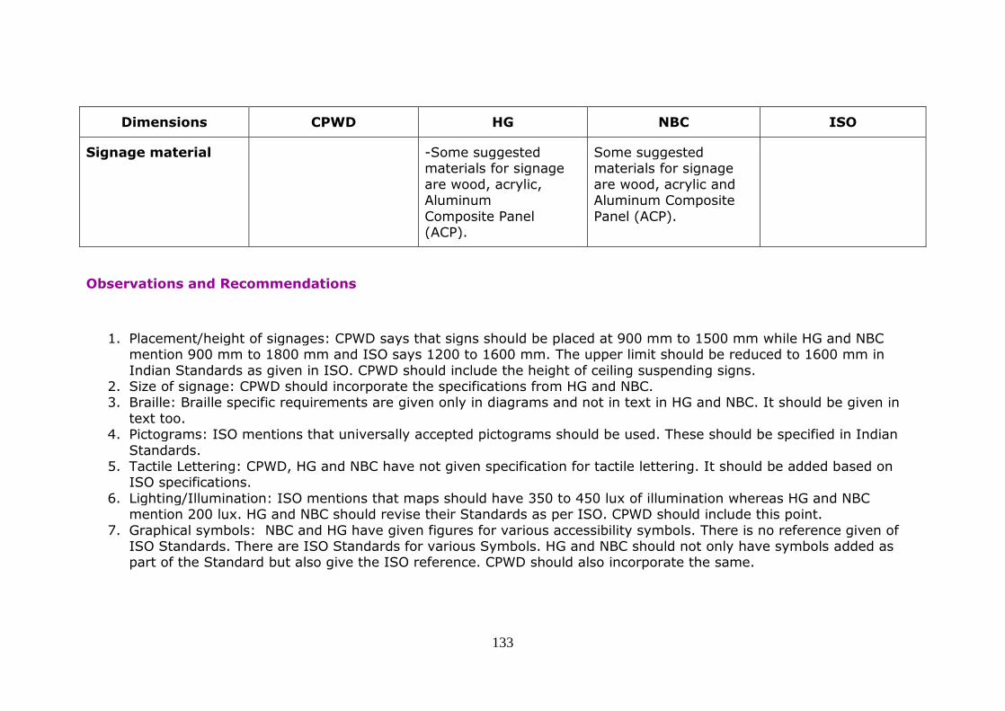
133
Dimensions CPWD HG NBC ISO
Signage material -Some suggested materials for signage
are wood, acrylic, Aluminum
Composite Panel (ACP).
Some suggested materials for signage
are wood, acrylic and Aluminum Composite
Panel (ACP).
Observations and Recommendations
1. Placement/height of signages: CPWD says that signs should be placed at 900 mm to 1500 mm while HG and NBC mention 900 mm to 1800 mm and ISO says 1200 to 1600 mm. The upper limit should be reduced to 1600 mm in
Indian Standards as given in ISO. CPWD should include the height of ceiling suspending signs. 2. Size of signage: CPWD should incorporate the specifications from HG and NBC. 3. Braille: Braille specific requirements are given only in diagrams and not in text in HG and NBC. It should be given in
text too. 4. Pictograms: ISO mentions that universally accepted pictograms should be used. These should be specified in Indian
Standards. 5. Tactile Lettering: CPWD, HG and NBC have not given specification for tactile lettering. It should be added based on
ISO specifications.
6. Lighting/Illumination: ISO mentions that maps should have 350 to 450 lux of illumination whereas HG and NBC mention 200 lux. HG and NBC should revise their Standards as per ISO. CPWD should include this point.
7. Graphical symbols: NBC and HG have given figures for various accessibility symbols. There is no reference given of ISO Standards. There are ISO Standards for various Symbols. HG and NBC should not only have symbols added as part of the Standard but also give the ISO reference. CPWD should also incorporate the same.

134
20 Conclusion
Based on the study, it was felt that the CPWD Guidelines are too simplified and have not covered many areas. It needs to include a lot more technical detail in order to make it appropriate as a reference.
The HG and NBC Guidelines are very similar. Most of the content of the NBC appears to have been taken from the HG. NBC appears to have included some relevant points from the ISO and therefore making it better than the HG. It was also noted
that, regarding some aspects, HG and NBC have given more stringent Standards than the ISO. However, there were some sections where the ISO was significantly more comprehensive and detailed than either the HG or the NBC. (Please refer to
the ‘observations and recommendations’ given at the end of each section for more information regarding the gaps).
It was also observed that, in several places, only the diagrams had the specifications but there were no details given in the text. Moreover, the diagrams/figures were not clear and were not synchronised with the text in some places. The diagrams
should be improved in all three Indian documents. The NBC should also improve on the presentation to make it easy to follow and be accessible.
It is very important to have ONE set of Standards in India. We recommend that the NBC, which is in the draft stage, must
incorporate the recommendations in order to make it comprehensive. The Urban Development Ministry and the CPWD ought to adopt the NBC Standards rather than having their own Guidelines. The NBC should be the only reference document for all
building bye-laws, guidelines for smart cities, green buildings, etc.
It must also be noted that the NBC provides standards for buildings in general. Now there are specific requirements for many different types of buildings which are not included in the NBC. Therefore, Standards have to be developed for residential
buildings, schools, cinema halls, hotels/restaurants, hospitals, offices, auditorium, bus stops, sports arenas, museums, historical buildings, religious places and so on.
It is important to mention here that that the requirements for accessibility have been given as an annexure in Part 3 of the NBC, ‘Annexure B, Anthropometrics and specific requirements for barrier free buildings and built environment’. These
specifications should also be included in the relevant chapters of the NBC. For example, issues concerning emergency evacuation should be in the fire and safety chapter; points related to lifts should be put in the chapter where general
135
specifications for lifts are given; standards concerning accessible toilets should be in the plumbing section; kerb ramps should be mentioned where requirements for footpaths are given and so on. NCPEDP, in collaboration with AccessAbility and
DEOC, had undertaken a study (March 2016) of the various draft chapters of NBC and the recommendations have been submitted to BIS.
Last, but not the least, it is important to state that all the Indian Guidelines appears to have been adopted from international
Standards and the source from where the specific information has been taken has not been mentioned. Unfortunately, there has been no authentic study undertaken in India, with respect to the accessibility needs of persons with different disabilities,
keeping in mind the range of assistive devices/technologies being used, cultural aspects, terrains in rural/urban/hilly regions, etc. ISO has mentioned at several places that national regulations have to be considered. Hence, research should be undertaken in order to develop an Indian Standard for accessibility of built environment which is suitable in the Indian
context.


